1
Contents
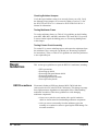
HP E1411A/B 5 1/2 Digit Multimeter Service Manual
Edition 2
Click here to Return to HP TS-5400 Systems On-Line Manuals Main Contents
Chapter 1. General Information . . . . . . . . . . . . . . . . . . . . . . . . . . . . . . . . . 11
Introduction . . . . . . . . . .
Safety Considerations . . . . .
Warnings and Cautions . .
Multimeter Description . . . .
Multimeter Specifications
Multimeter Serial Numbers
Multimeter Options . . . .
Recommended
Test Equipment . . . . . . .
.
.
.
.
.
.
.
.
.
.
.
.
.
.
.
.
.
.
.
.
.
.
.
.
.
.
.
.
.
.
.
.
.
.
.
.
.
.
.
.
.
.
.
.
.
.
.
.
.
.
.
.
.
.
.
.
.
.
.
.
.
.
.
.
.
.
.
.
.
.
.
.
.
.
.
.
.
.
.
.
.
.
.
.
.
.
.
.
.
.
.
.
.
.
.
.
.
.
.
.
.
.
.
.
.
.
.
.
.
.
.
.
.
.
.
.
.
.
.
.
.
.
.
.
.
.
.
.
.
.
.
.
.
.
.
.
.
.
.
.
.
.
.
.
.
.
.
.
.
.
.
.
.
.
.
.
.
.
.
.
.
.
.
.
.
.
.
.
.
.
.
.
.
.
.
.
.
.
.
.
.
.
.
.
.
.
.
.
.
.
.
.
.
.
.
.
.
.
.
.
.
.
.
.
.
.
.
.
.
.
11
11
12
13
13
14
14
. . . . . . . . . . . . . . . . . . . . . . . . . . . . . . 14
Chapter 2. Installation . . . . . . . . . . . . . . . . . . . . . . . . . . . . . . . . . . . . . . 15
Introduction . . . . . .
Initial Inspection . . .
Preparation for Use . .
Shipping the Multimeter
.
.
.
.
.
.
.
.
.
.
.
.
.
.
.
.
.
.
.
.
.
.
.
.
.
.
.
.
.
.
.
.
.
.
.
.
.
.
.
.
.
.
.
.
.
.
.
.
.
.
.
.
.
.
.
.
.
.
.
.
.
.
.
.
.
.
.
.
.
.
.
.
.
.
.
.
.
.
.
.
.
.
.
.
.
.
.
.
.
.
.
.
.
.
.
.
.
.
.
.
.
.
.
.
.
.
.
.
.
.
.
.
.
.
.
.
.
.
.
.
.
.
.
.
.
.
.
.
.
.
.
.
.
.
.
.
15
15
15
16
Chapter 3. Operating Instructions . . . . . . . . . . . . . . . . . . . . . . . . . . . . . . . 17
Introduction . . . . . . . . . . . .
Multimeter Operation . . . . . . .
Operator’s Check . . . . . . . . .
Self-Test Procedure . . . . . .
Example: Multimeter Self-Test
.
.
.
.
.
.
.
.
.
.
.
.
.
.
.
.
.
.
.
.
.
.
.
.
.
.
.
.
.
.
.
.
.
.
.
.
.
.
.
.
.
.
.
.
.
.
.
.
.
.
.
.
.
.
.
.
.
.
.
.
.
.
.
.
.
.
.
.
.
.
.
.
.
.
.
.
.
.
.
.
.
.
.
.
.
.
.
.
.
.
.
.
.
.
.
.
.
.
.
.
.
.
.
.
.
.
.
.
.
.
.
.
.
.
.
.
.
.
.
.
.
.
.
.
.
.
.
.
.
.
.
.
.
.
.
.
.
.
.
.
17
17
17
17
18
Chapter 4. Verification Tests . . . . . . . . . . . . . . . . . . . . . . . . . . . . . . . . . . . 19
Introduction . . . . . . . . . . .
Test Conditions / Procedures
Performance Test Record .
Verification Test Examples .
Functional Verification Test . . .
Self-Test Procedure . . . .
Example: Self-Test . . . . .
Operation Verification Tests . . .
Performance Verification Tests .
Performance Test Record . . . .
Multimeter Accuracy . . . .
Measurement Uncertainty .
Test Accuracy Ratio (TAR)
.
.
.
.
.
.
.
.
.
.
.
.
.
.
.
.
.
.
.
.
.
.
.
.
.
.
.
.
.
.
.
.
.
.
.
.
.
.
.
.
.
.
.
.
.
.
.
.
.
.
.
.
.
.
.
.
.
.
.
.
.
.
.
.
.
.
.
.
.
.
.
.
.
.
.
.
.
.
.
.
.
.
.
.
.
.
.
.
.
.
.
.
.
.
.
.
.
.
.
.
.
.
.
.
.
.
.
.
.
.
.
.
.
.
.
.
.
.
.
.
.
.
.
.
.
.
.
.
.
.
.
.
.
.
.
.
.
.
.
.
.
.
.
.
.
.
.
.
.
.
.
.
.
.
.
.
.
.
.
.
.
.
.
.
.
.
.
.
.
.
.
.
.
.
.
.
.
.
.
.
.
.
.
.
.
.
.
.
.
.
.
.
.
.
.
.
.
.
.
.
.
.
.
.
.
.
.
.
.
.
.
.
.
.
.
.
.
.
.
.
.
.
.
.
.
.
.
.
.
.
.
.
.
.
.
.
.
.
.
.
.
.
.
.
.
.
.
.
.
.
.
.
.
.
.
.
.
.
.
.
.
.
.
.
.
.
.
.
.
.
.
.
.
.
.
.
.
.
.
.
.
.
.
.
.
.
.
.
.
.
.
.
.
.
.
.
.
.
.
.
.
.
.
.
.
.
.
.
.
.
.
.
.
.
.
.
.
.
.
.
.
.
.
.
.
.
.
.
.
.
.
.
.
.
.
.
.
.
.
.
.
.
.
.
.
.
.
.
.
.
.
.
.
.
.
.
.
.
.
.
.
.
.
.
.
.
.
.
.
.
.
.
.
.
.
.
.
19
19
19
20
20
20
21
21
21
32
32
32
32
Chapter 5. Adjustments . . . . . . . . . . . . . . . . . . . . . . . . . . . . . . . . . . . . . 37
Introduction . . . . . . . . . . . . . . . . . .
Adjustment Conditions / Procedures . . .
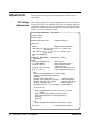
DC Voltage Adjustments . . . . . . . . . . .
Equipment Setup . . . . . . . . . . . . .
Adjustment Procedure . . . . . . . . . .
Example: DC Voltage Adjustments . . .
AC Voltage Adjustments . . . . . . . . . . .
Equipment Setup . . . . . . . . . . . . .
Adjustment Procedure . . . . . . . . . .
Resistance Adjustments . . . . . . . . . . . .
Equipment Setup . . . . . . . . . . . . .
Adjustment Procedure . . . . . . . . . .
Example: 4-Wire Resistance Adjustments
Calibration Errors . . . . . . . . . . . . . . .
.
.
.
.
.
.
.
.
.
.
.
.
.
.
.
.
.
.
.
.
.
.
.
.
.
.
.
.
.
.
.
.
.
.
.
.
.
.
.
.
.
.
.
.
.
.
.
.
.
.
.
.
.
.
.
.
.
.
.
.
.
.
.
.
.
.
.
.
.
.
.
.
.
.
.
.
.
.
.
.
.
.
.
.
.
.
.
.
.
.
.
.
.
.
.
.
.
.
.
.
.
.
.
.
.
.
.
.
.
.
.
.
.
.
.
.
.
.
.
.
.
.
.
.
.
.
.
.
.
.
.
.
.
.
.
.
.
.
.
.
.
.
.
.
.
.
.
.
.
.
.
.
.
.
.
.
.
.
.
.
.
.
.
.
.
.
.
.
.
.
.
.
.
.
.
.
.
.
.
.
.
.
.
.
.
.
.
.
.
.
.
.
.
.
.
.
.
.
.
.
.
.
.
.
.
.
.
.
.
.
.
.
.
.
.
.
.
.
.
.
.
.
.
.
.
.
.
.
.
.
.
.
.
.
.
.
.
.
.
.
.
.
.
.
.
.
.
.
.
.
.
.
.
.
.
.
.
.
.
.
.
.
.
.
.
.
.
.
.
.
.
.
.
.
.
.
.
.
.
.
.
.
.
.
.
.
.
.
.
.
.
.
.
.
.
.
.
.
.
.
.
.
.
.
.
.
.
.
37
37
38
38
39
39
41
41
42
44
44
45
46
47
Chapter 6. Replaceable Parts . . . . . . . . . . . . . . . . . . . . . . . . . . . . . . . . . . 49
Introduction . . . . . . .
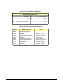
Exchange Assemblies
Ordering Information
Replaceable Parts List . .
.
.
.
.
.
.
.
.
.
.
.
.
.
.
.
.
.
.
.
.
.
.
.
.
.
.
.
.
.
.
.
.
.
.
.
.
.
.
.
.
.
.
.
.
.
.
.
.
.
.
.
.
.
.
.
.
.
.
.
.
.
.
.
.
.
.
.
.
.
.
.
.
.
.
.
.
.
.
.
.
.
.
.
.
.
.
.
.
.
.
.
.
.
.
.
.
.
.
.
.
.
.
.
.
.
.
.
.
.
.
.
.
.
.
.
.
.
.
.
.
.
.
.
.
.
.
.
.
.
.
.
.
49
49
49
49
Chapter 7. Manual Changes . . . . . . . . . . . . . . . . . . . . . . . . . . . . . . . . . . . 55
Introduction . . . . . . . . . . . . . . . . . . . . . . . . . . . . . . . . . . . . . . . . 55
Chapter 8. Service . . . . . . . . . . . . . . . . . . . . . . . . . . . . . . . . . . . . . . . . . 57
Introduction . . . . . . . . . . . . .
Equipment Required . . . . . .
Service Aids . . . . . . . . . .
TroubleshootingTechniques . . . . .
Identifying the Problem . . . . .
Testing Assemblies . . . . . . .
Repair Guidelines . . . . . . . . . .
ESD Precautions . . . . . . . .
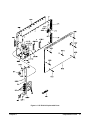
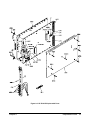
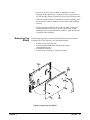
Removing Top Shield . . . . . .
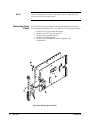
Removing Front Panel . . . . .
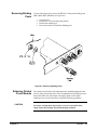
Removing Binding Posts . . . .
Soldering Printed Circuit Boards
Post-Repair Safety Checks . . .
.
.
.
.
.
.
.
.
.
.
.
.
.
.
.
.
.
.
.
.
.
.
.
.
.
.
.
.
.
.
.
.
.
.
.
.
.
.
.
.
.
.
.
.
.
.
.
.
.
.
.
.
.
.
.
.
.
.
.
.
.
.
.
.
.
.
.
.
.
.
.
.
.
.
.
.
.
.
.
.
.
.
.
.
.
.
.
.
.
.
.
.
.
.
.
.
.
.
.
.
.
.
.
.
.
.
.
.
.
.
.
.
.
.
.
.
.
.
.
.
.
.
.
.
.
.
.
.
.
.
.
.
.
.
.
.
.
.
.
.
.
.
.
.
.
.
.
.
.
.
.
.
.
.
.
.
.
.
.
.
.
.
.
.
.
.
.
.
.
.
.
.
.
.
.
.
.
.
.
.
.
.
.
.
.
.
.
.
.
.
.
.
.
.
.
.
.
.
.
.
.
.
.
.
.
.
.
.
.
.
.
.
.
.
.
.
.
.
.
.
.
.
.
.
.
.
.
.
.
.
.
.
.
.
.
.
.
.
.
.
.
.
.
.
.
.
.
.
.
.
.
.
.
.
.
.
.
.
.
.
.
.
.
.
.
.
.
.
.
.
.
.
.
.
.
.
.
.
.
.
.
.
.
.
.
.
.
.
.
.
.
.
.
.
.
.
.
.
.
.
.
.
.
.
.
.
.
.
.
.
.
.
.
.
.
.
.
.
.
.
.
.
.
.
.
.
.
.
.
.
.
.
.
.
.
.
.
.
.
.
.
.
.
.
.
.
.
.
.
.
.
57
57
57
58
58
59
60
60
61
62
63
63
64
Appendix A. Calculating Multimeter Accuracy . . . . . . . . . . . . . . . . . . . . . . . . 65
Introduction . . . . . . . . . . . . . .
Multimeter Accuracy Calculations . .
DC Voltage Accuracy Equations .
AC Voltage Accuracy Equations .
4-Wire Ohms Accuracy Equations
Measurement Uncertainty Calculations
.
.
.
.
.
.
.
.
.
.
.
.
.
.
.
.
.
.
.
.
.
.
.
.
.
.
.
.
.
.
.
.
.
.
.
.
.
.
.
.
.
.
.
.
.
.
.
.
.
.
.
.
.
.
.
.
.
.
.
.
.
.
.
.
.
.
.
.
.
.
.
.
.
.
.
.
.
.
.
.
.
.
.
.
.
.
.
.
.
.
.
.
.
.
.
.
.
.
.
.
.
.
.
.
.
.
.
.
.
.
.
.
.
.
.
.
.
.
.
.
.
.
.
.
.
.
.
.
.
.
.
.
.
.
.
.
.
.
.
.
.
.
.
.
.
.
.
.
.
.
.
.
.
.
.
.
65
66
66
67
67
68
Calculate DCV Measurement Uncertainty . . . .
Calculate ACV Measurement Uncertainty . . . .
Calculate Resistance Measurement Uncertainty
Test Accuracy Ratio (TAR) Calculations . . . . . . .
.
.
.
.
.
.
.
.
.
.
.
.
.
.
.
.
.
.
.
.
.
.
.
.
.
.
.
.
.
.
.
.
.
.
.
.
.
.
.
.
.
.
.
.
.
.
.
.
.
.
.
.
.
.
.
.
.
.
.
.
.
.
.
.
.
.
.
.
.
.
.
.
68
69
69
70
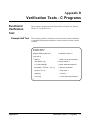
Appendix B. Verification Tests - C Programs . . . . . . . . . . . . . . . . . . . . . . . . . 71
Functional Verification Test . . . .
Example:Self Test . . . . . .
Performance Verification Tests . .
Example: Zero Volt DCV Test
Example: DC Voltage Test . .
Example: AC Voltage Test . .
Example: Resistance Test . . .
Adjustments . . . . . . . . . . . .
DC Voltage Adjustments . . .
AC Voltage Adjustments . . .
Resistance Adjustments . . . .
.
.
.
.
.
.
.
.
.
.
.
.
.
.
.
.
.
.
.
.
.
.
.
.
.
.
.
.
.
.
.
.
.
.
.
.
.
.
.
.
.
.
.
.
.
.
.
.
.
.
.
.
.
.
.
.
.
.
.
.
.
.
.
.
.
.
.
.
.
.
.
.
.
.
.
.
.
.
.
.
.
.
.
.
.
.
.
.
.
.
.
.
.
.
.
.
.
.
.
.
.
.
.
.
.
.
.
.
.
.
.
.
.
.
.
.
.
.
.
.
.
.
.
.
.
.
.
.
.
.
.
.
.
.
.
.
.
.
.
.
.
.
.
.
.
.
.
.
.
.
.
.
.
.
.
.
.
.
.
.
.
.
.
.
.
.
.
.
.
.
.
.
.
.
.
.
.
.
.
.
.
.
.
.
.
.
.
.
.
.
.
.
.
.
.
.
.
.
.
.
.
.
.
.
.
.
.
.
.
.
.
.
.
.
.
.
.
.
.
.
.
.
.
.
.
.
.
.
.
.
.
.
.
.
.
.
.
.
.
.
.
.
.
.
.
.
.
.
.
.
.
.
.
.
.
.
.
.
.
.
.
.
.
.
.
.
.
.
.
.
.
.
.
.
.
.
.
.
.
.
.
.
.
.
.
.
.
.
.
.
.
.
.
.
.
.
.
.
.
.
.
.
.
.
.
.
.
.
71
71
72
72
73
74
75
76
76
77
78
Notes
Certification
Hewlett-Packard Company certifies that this product met its published specifications at the time of shipment from the factory. HewlettPackard further certifies that its calibration measurements are traceable to the United States National Institute of Standards and Technology (formerly National Bureau of Standards), to the extent allowed by that organization’s calibration facility, and to the calibration
facilities of other International Standards Organization members.
Warranty
This Hewlett-Packard product is warranted against defects in materials and workmanship for a period of three years from date of shipment. Duration and conditions of warranty for this product may be superseded when the product is integrated into (becomes a part of)
other HP products. During the warranty period, Hewlett-Packard Company will, at its option, either repair or replace products which
prove to be defective.
For warranty service or repair, this product must be returned to a service facility designated by Hewlett-Packard (HP). Buyer shall prepay shipping charges to HP and HP shall pay shipping charges to return the product to Buyer. However, Buyer shall pay all shipping
charges, duties, and taxes for products returned to HP from another country.
HP warrants that its software and firmware designated by HP for use with a product will execute its programming instructions when
properly installed on that product. HP does not warrant that the operation of the product, or software, or firmware will be uninterrupted
or error free.
Limitation Of Warranty
The foregoing warranty shall not apply to defects resulting from improper or inadequate maintenance by Buyer, Buyer-supplied products or interfacing, unauthorized modification or misuse, operation outside of the environmental specifications for the product, or improper site preparation or maintenance.
The design and implementation of any circuit on this product is the sole responsibility of the Buyer. HP does not warrant the Buyer’s
circuitry or malfunctions of HP products that result from the Buyer’s circuitry. In addition, HP does not warrant any damage that occurs as a result of the Buyer’s circuit or any defects that result from Buyer-supplied products.
NO OTHER WARRANTY IS EXPRESSED OR IMPLIED. HP SPECIFICALLY DISCLAIMS THE IMPLIED WARRANTIES OF
MERCHANTABILITY AND FITNESS FOR A PARTICULAR PURPOSE.
Exclusive Remedies
THE REMEDIES PROVIDED HEREIN ARE BUYER’S SOLE AND EXCLUSIVE REMEDIES. HP SHALL NOT BE LIABLE
FOR ANY DIRECT, INDIRECT, SPECIAL, INCIDENTAL, OR CONSEQUENTIAL DAMAGES, WHETHER BASED ON CONTRACT, TORT, OR ANY OTHER LEGAL THEORY.
Notice
The information contained in this document is subject to change without notice. HEWLETT-PACKARD (HP) MAKES NO WARRANTY OF ANY KIND WITH REGARD TO THIS MATERIAL, INCLUDING, BUT NOT LIMITED TO, THE IMPLIED WARRANTIES OF MERCHANTABILITY AND FITNESS FOR A PARTICULAR PURPOSE. HP shall not be liable for errors contained
herein or for incidental or consequential damages in connection with the furnishing, performance or use of this material. This document contains proprietary information which is protected by copyright. All rights are reserved. No part of this document may be photocopied, reproduced, or translated to another language without the prior written consent of Hewlett-Packard Company. HP assumes no
responsibility for the use or reliability of its software on equipment that is not furnished by HP.
U.S. Government Restricted Rights
The Software and Documentation have been developed entirely at private expense. They are delivered and licensed as "commercial
computer software" as defined in DFARS 252.227- 7013 (Oct 1988), DFARS 252.211-7015 (May 1991) or DFARS 252.227-7014 (Jun
1995), as a "commercial item" as defined in FAR 2.101(a), or as "Restricted computer software" as defined in FAR 52.227-19 (Jun
1987)(or any equivalent agency regulation or contract clause), whichever is applicable. You have only those rights provided for such
Software and Documentation by the applicable FAR or DFARS clause or the HP standard software agreement for the product involved.
HP E1411A/E1411B 5 1/2-Digit Multimeter Service Manual
Edition 2
Copyright © 1996 Hewlett-Packard Company. All Rights Reserved.
HP E1411A/B Service Manual
5
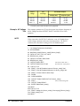
Documentation History
All Editions and Updates of this manual and their creation date are listed below. The first Edition of the manual is Edition 1. The Edition number increments by 1 whenever the manual is revised. Updates, which are issued between Editions, contain replacement pages
to correct or add additional information to the current Edition of the manual. Whenever a new Edition is created, it will contain all of
the Update information for the previous Edition. Each new Edition or Update also includes a revised copy of this documentation history page.
Edition 1 (Part Number E1411-90000). . . . . . . . . . . . . . . . . . . . . . October 1995
Edition 2 (Part Number E1411-90011). . . . . . . . . . . . . . . . . . . . . . . August 1996
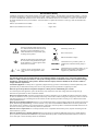
Safety Symbols
Instruction manual symbol affixed to product. Indicates that the user must refer to the
manual for specific WARNING or CAUTION information to avoid personal injury
or damage to the product.
Alternating current (AC).
Direct current (DC).
Indicates hazardous voltages.
Indicates the field wiring terminal that must
be connected to earth ground before operating the equipment—protects against electrical shock in case of fault.
or
Frame or chassis ground terminal—typically connects to the equipment’s metal
frame.
WARNING
Calls attention to a procedure, practice, or
condition that could cause bodily injury or
death.
CAUTION
Calls attention to a procedure, practice, or condition that could possibly cause damage to
equipment or permanent loss of data.
WARNINGS
The following general safety precautions must be observed during all phases of operation, service, and repair of this product.
Failure to comply with these precautions or with specific warnings elsewhere in this manual violates safety standards of design,
manufacture, and intended use of the product. Hewlett-Packard Company assumes no liability for the customer’s failure to
comply with these requirements.
Ground the equipment: For Safety Class 1 equipment (equipment having a protective earth terminal), an uninterruptible safety earth
ground must be provided from the mains power source to the product input wiring terminals or supplied power cable.
DO NOT operate the product in an explosive atmosphere or in the presence of flammable gases or fumes.
For continued protection against fire, replace the line fuse(s) only with fuse(s) of the same voltage and current rating and type.
DO NOT use repaired fuses or short-circuited fuse holders.
Keep away from live circuits: Operating personnel must not remove equipment covers or shields. Procedures involving the removal
of covers or shields are for use by service-trained personnel only. Under certain conditions, dangerous voltages may exist even with the
equipment switched off. To avoid dangerous electrical shock, DO NOT perform procedures involving cover or shield removal unless
you are qualified to do so.
DO NOT operate damaged equipment: Whenever it is possible that the safety protection features built into this product have been impaired, either through physical damage, excessive moisture, or any other reason, REMOVE POWER and do not use the product until
safe operation can be verified by service-trained personnel. If necessary, return the product to a Hewlett-Packard Sales and Service Office for service and repair to ensure that safety features are maintained.
DO NOT service or adjust alone: Do not attempt internal service or adjustment unless another person, capable of rendering first aid
and resuscitation, is present.
DO NOT substitute parts or modify equipment: Because of the danger of introducing additional hazards, do not install substitute
parts or perform any unauthorized modification to the product. Return the product to a Hewlett-Packard Sales and Service Office for
service and repair to ensure that safety features are maintained.
6
HP E1411A/B Service Manual
Declaration of Conformity
according to ISO/IEC Guide 22 and EN 45014
Manufacturer’s Name:
Hewlett-Packard Company
Loveland Manufacturing Center
Manufacturer’s Address:
815 14th Street S.W.
Loveland, Colorado 80537
declares, that the product:
Product Name:
5 1/2-Digit Multimeter
Model Number:
HP E1411A/HP E1411B
Product Options:
All
conforms to the following Product Specifications:
Safety:
IEC 1010-1 (1990) Incl. Amend 1 (1992)/EN61010-1(1993)
CSA C22.2#1010.1 (1992)
UL 3111
EMC:
CISPR 11:1990/EN55011 (1991): Group 1, Class A
EN50082-1:1992
IEC 801-2:1991 : 4kV CD, 8kV AD
IEC 801-3:1984 : 3 V/m
IEC 801-4:1988 : 1kV Power Line, 0.5kV signal lines
ENV50141:1993/prEN50082-1 (1995): 3 Vrms
ENV50142:1994/prEN50082-1 (1995): 1 kV CM, 0.5kV DM
IEC1000-4-8:1993/prEN50082-1 (1995): 3 A/m
EN61000-4-11:1994/prEN50082-1 (1995): 30%,10ms 60%,100ms
Supplementary Information: The product herewith complies with the requirements of the Low Voltage Directive
73/23/EEC and the EMC Directive 89/336/EEC (inclusive 93/68/EEC) and carries the "CE" mark accordingly.
Tested in a typical HP C-Size VXI mainframe configuration.
December 30, 1995
Jim White, QA Manager
European contact: Your local Hewlett-Packard Sales and Service Office or Hewlett-Packard GmbH, Department
HQ-TRE, Herrenberger Straße 130, D-71034 Böblingen, Germany (FAX +49-7031-14-3143).
HP E1411A/B Service Manual
7
Notes
8
HP E1411A/B Service Manual
Please fold and tape for mailing
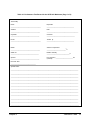
Reader Comment Sheet
HP E1411A/E1411B 5 1/2-Digit Multimeter Service Manual
Edition 2
You can help us improve our manuals by sharing your comments and suggestions. In appreciation of your time, we will
enter you in a quarterly drawing for a Hewlett-Packard Palmtop Personal Computer (U.S. government employees
are not eligible for the drawing).
Your Name
City, State/Province
Company Name
Country
Job Title
Zip/Postal Code
Address
Telephone Number with Area Code
Please list the system controller, operating system, programming language, and plug-in modules you are using.
fold here
cut along this line
NO POSTAGE
NECESSARY
IF MAILED
IN THE
UNITED STATES
BUSINESS REPLY MAIL
FIRST CLASS
PERMIT NO. 37
LOVELAND, CO
HEWLETT-PACKARD COMPANY
Measurement Systems Division
Learning Products Department
P.O. Box 301
Loveland, CO 80539-9984
fold here
Please pencil-in one circle for each statement below:
• The documentation is well organized.
• Instructions are easy to understand.
• The documentation is clearly written.
• Examples are clear and useful.
• Illustrations are clear and helpful.
• The documentation meets my overall expectations.
Please write any comments or suggestions below--be specific.
Disagree
O
O
O
O
O
O
O
O
O
O
O
O
O
O
O
O
O
O
O
O
O
O
O
O
Agree
O
O
O
O
O
O
10
HP E1411A/E1411B Service Manual
Chapter 1
General Information
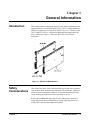
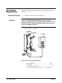
Introduction
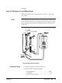
This manual contains information required to test, adjust, troubleshoot, and
repair the HP E1411A and HP E1411B C-Size VXI 5 1/2-Digit Multimeters
(HP E1411 multimeter). See the HP E1326A/E1411A User’s Manual or the
HP E1326B/E1411B User’s Manual for additional information on the HP
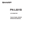
E1411 multimeter. Figure 1-1 shows the HP E1411A and E1411B
multimeters.
Figure 1-1. HP E1411A/B Multimeters
Safety
Considerations
This product is a Safety Class I instrument that is provided with a protective
earth terminal when installed in the mainframe. The mainframe, multimeter,
and all related documentation should be reviewed for familiarization with
safety markings and instructions before operation or service.
Refer to the WARNINGS page (page 4) in this manual for a summary of
safety information. Safety information for testing, adjusting, and service
follows and is also found throughout this manual.
Chapter 1
General Information
11
Warnings and
Cautions
WARNING
This section contains WARNINGS which must be followed for your
protection and CAUTIONS which must be followed to avoid damage to the
equipment when performing instrument maintenance or repair.
SERVICE-TRAINED PERSONNEL ONLY. The information in this
manual is for service-trained personnel who are familiar with
electronic circuitry and are aware of the hazards involved. To
avoid personal injury or damage to the instrument, do not
perform procedures in this manual or do any servicing unless
you are qualified to do so.
CHECK MAINFRAME POWER SETTINGS. Before applying
power, verify that the mainframe setting matches the line
voltage and the correct fuse is installed. An uninterruptible
safety earth ground must be provided from the main power
source to the supplied power cord set.
GROUNDING REQUIREMENTS. Interruption of the protective
(grounding) conductor (inside or outside the mainframe) or
disconnecting the protective earth terminal will cause a
potential shock hazard that could result in personal injury.
(Grounding one conductor of a two-conductor outlet is not
sufficient protection.)
IMPAIRED PROTECTION. Whenever it is likely that instrument
protection has been impaired, the mainframe must be made
inoperative and be secured against any unintended operation.
REMOVE POWER IF POSSIBLE. Some procedures in this
manual may be performed with power supplied to the
mainframe while protective covers are removed. Energy
available at many points may, if contacted, result in personal
injury. (If maintenance can be performed without power applied,
the power should be removed.)
USING AUTOTRANSFORMERS. If the mainframe is to be
energized via an autotransformer (for voltage reduction) make
sure the common terminal is connected to neutral (that is, the
grounded side of the main’s supply).
CAPACITOR VOLTAGES. Capacitors inside the mainframe may
remain charged even when the mainframe has been
disconnected from its source of supply.
12
General Information
Chapter 1
WARNING
CAUTION
Multimeter
Description
NOTE
USE PROPER FUSES. For continued protection against fire
hazard, replace the line fuse(s) only with fuses of the same
current rating and type (such as normal blow, time delay, etc.).
Do not use repaired fuses or short-circuited fuseholders.
Static electricity is a major cause of component failure. To prevent
damage to the electrical components in the multimeter, observe
anti-static techniques whenever working on the multimeter.
The HP E1411 multimeter is an "instrument" in the slots of a VXIbus
mainframe. As such, it is assigned an error queue, input and output buffers,
status registers, and is allocated a portion of mainframe memory for reading
storage.
Instruments are based on the logical addresses of the plug-in modules. See
the HP 75000 Series C Installation and Getting Started Guide to set the
addresses to create an instrument.
The instrument may consist of a multimeter only (stand-alone operation), or
can include relay or FET multiplexers (scanning multimeter operation). The
instrument is operated from a computer using Standard Commands for
Programmable Instruments (SCPI) language.
In stand-alone operation, input signals are connected to the multimeter’s
external (faceplate) terminals. In scanning multimeter operation, input
signals are connected to the multiplexer channels. The multimeter is linked
to relay multiplexers via an analog bus cable. The multimeter is linked to
FET multiplexers via an analog bus cable and a digital bus cable.
Multimeter
Specifications
Chapter 1
Multimeter specifications are listed in Appendix A of the HP
E1326A/E1411A User’s Manual or the E1326B/E1411B User’s Manual.
These specifications are the performance standards or limits against which
the instrument may be tested.
General Information
13
Multimeter Serial
Numbers
Multimeters covered by this manual are identified by a serial number prefix
listed on the title page. Hewlett-Packard uses a two part serial number in the
form 0000A00000, where 0000 is the serial prefix, A is the country of
origin (A=USA) and 00000 is the serial suffix. The serial number prefix
identifies a series of identical instruments. The serial number suffix is
assigned sequentially to each instrument.
If the serial number prefix of your instrument is greater than the one listed
on the title page, a Manual Update (as required) will explain how to adapt
this manual to your instrument. If the serial number prefix of your
instrument is lower than the one listed on the title page, information
contained in Chapter 7- Manual Changes will explain how to adapt this
manual to your instrument.
Multimeter Options
Recommended
Test
Equipment
There are no electrical or mechanical options available for the HP E1411
multimeters. However, for the HP E1411B, you can order Option 1BN that
provides a MIL-STD-45662A Calibration Certificate. Contact your nearest
Hewlett-Packard Sales and Support Office for information on Option 1BN.
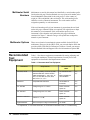
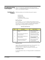
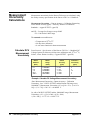
Table 1-1 lists the test equipment recommended for testing, adjusting and
servicing the multimeter. Essential requirements for each piece of test
equipment are described in the Requirements column.
Table 1-1. Recommended Test Equipment
Instrument
Requirements
Recommended
Model
Use*
Controller, HP-IB
HP-IB compatibility as defined by IEEE
Standard 488-1987 and the identical
ANSI Standard MC1.1: SH1, AH1, T2,
TE0, L2, LE0, SR0, RL0, PP0, DC0,
DT0, and C1, 2, 3, 4, 5
HP 9000 Series 300
or
IBM Compatible PC
with HP BASIC
A,F,
P,T
Mainframe
Compatible with multimeter
HP E1400B/T or
E1421A/B
A,F,
P,T
AC Standard
Voltage Range 0.1 V to 300 V
Datron 4708 with
Option 20
A,P
DC Standard
Voltage Range 0.07 V to 300 V
Datron 4708 with
Option 10
A,P
Resistance Standard
Values 1 kΩ to 1 MΩ
Datron 4708 with
Option 30
A,P
Digital Multimeter
General Purpose Voltage and Resistance
HP 3458A
T
*A = Adjustments, F = Functional Verification, P = Performance Verification Tests, T = Troubleshooting
14
General Information
Chapter 1
Chapter 2
Installation
Introduction
This chapter provides information to install the HP E1411 multimeter,
including initial inspection, preparation for use, environment, storage and
shipment.
Initial
Inspection
Inspect the shipping container for damage. If the shipping container or
cushioning material is damaged, keep the container until the shipment
contents have been checked and the instrument has been checked
mechanically and electrically. See Figure 1-1 in Chapter 1 - General
Information for shipment contents. See Chapter 4 - Verification Tests for
procedures to check electrical performance.
WARNING
To avoid possible hazardous electrical shock, do not perform
electrical tests if there are signs of shipping damage to any
portion of the outer enclosure (covers, panels, etc.).
If the contents are incomplete, if there is mechanical damage or defect, or if
the instrument does not pass the electrical performance tests, notify your
nearest Hewlett-Packard Sales and Support Office. If the shipping container
is damaged or the cushioning material shows signs of stress, notify the
carrier as well as Hewlett-Packard, and keep the shipping materials for the
carrier’s inspection.
Preparation for
Use
See Chapter 2 of the HP E1326A/E1411A User’s Manual or the
E1326B/E1411B User’s Manual to prepare an HP E1411 multimeter for
use. See the appropriate mainframe user’s manual(s) to prepare your
mainframe. If your mainframe is not manufactured by Hewlett-Packard,
consult the manufacturer for a list of available manual(s).
Recommended operating environment for the HP E1411 multimeters is 0oC
to +55oC with relative humidity <65% (0 oC to +40oC). The instrument
should be stored in a clean, dry environment. For storage and shipment, the
temperature range is -40oC to +75oC with relative humidity <65% (0oC to
+40oC).
Chapter 2
Installation
15
Shipping the
Multimeter
If you need to return an HP E1411 multimeter to Hewlett-Packard,
first remove any adapters or connectors before packaging the instrument for
shipment. When you return the instrument to Hewlett-Packard, attach a tag
to the instrument identifying the owner and indicating service or repair
required. In any correspondence, refer to the instrument by model number
and full serial number.
When shipping the instrument, we recommend using containers and
materials identical to those used in factory packaging, which are available
through Hewlett-Packard Sales and Support Offices. Mark the shipping
container "FRAGILE" to assure careful handling.
If you use other (commercially available) shipping materials, wrap the
instrument in heavy paper or plastic. Use a strong shipping container. A
double-wall carton of 2.4 MPa (350 psi) test material is adequate.
Use enough shock-absorbing material (75 to 100 mm layer; 3 to 4 inches)
around all sides of the instrument to provide firm cushion and prevent
movement in the container. Protect the front panel with cardboard. Seal the
shipping container securely and mark the container "FRAGILE" to assure
careful handling.
16
Installation
Chapter 2
Chapter 3
Operating Instructions
Introduction
This chapter lists operating information for the HP E1411 multimeter,
including:
• Multimeter operation
• Operator’s check (self-test)
Multimeter
Operation
Operator’s
Check
See the HP E1326A/E1411A User’s Manual or the E1326B/E1411B User’s
Manual for multimeter operation, including:
•
•
•
•
Getting started
Configuring the multimeter
Using the multimeter
Understanding the multimeter
•
•
•
•
Multimeter command reference
Multimeter specifications
Multimeter error messages
Register-based programming
The Operator’s Check for the HP E1411 multimeter consists of sending the
self-test (*TST?) command and checking the return. The operator’s check
can be used to verify the multimeter is connected properly and is responding
to the self-test command.
As required, see the mainframe user’s manual for information on address
selection. See the HP E1326A/E1411A User’s Manual or the
E1326B/E1411B User’s Manual for information on multimeter SCPI
commands.
Self-Test Procedure
1. Verify the multimeter is properly installed in the mainframe and
the mainframe has passed its power-on sequence test.
2. Execute the multimeter functional test using the *TST? command
(see example following).
3. A "0" returned means no self-test failure, while "1", "2", "3", or "4"
returned means a failure was detected. See Chapter 8 - Service for
troubleshooting information (see NOTE following).
Chapter 3
Operating Instructions
17
NOTE
Example:
Multimeter Self-Test
Test failures can be caused by improper cabling, improper selection of the
interface select code, primary, and/or secondary address setting. Verify
proper connection and address selection before troubleshooting.
An example follows which uses an HP 9000 Series 300 computer with HP
BASIC and a multimeter address of 70903.
10 OUTPUT 70903;"*TST?"
Send the self-test command
20 ENTER 70903;A
Enter self-test result
30 PRINT A
40 END
18
Operating Instructions
Chapter 3
Chapter 4
Verification Tests
Introduction
The three levels of test procedures described in this chapter are used
to verify that the HP E1411 multimeter:
• is functional (Functional Verification)
• meets selected testable specifications (Operation Verification)
• meets all testable specifications (Performance Verification)
WARNING
Test Conditions /
Procedures
Do not perform any of the following verification tests unless
you are a qualified, service-trained person and have read the
WARNINGS and CAUTIONS in Chapter 1 - General Information.
For valid tests, all test equipment and the multimeter must have a one hour
warmup, the line voltage must be 115/230 Vac ± 10%, and multimeter Auto
Zero must be set to ON. See Table 1-1, Recommended Test Equipment, for
test equipment requirements.
For best test accuracy, the ambient temperature of the test area should be
between 18oC and 28oC and stable to within ±1oC. You should perform the
Performance Verification tests at least once a year. For heavy use or severe
operating environments, perform the tests more often.
The verification tests assume the person performing the tests understands
how to operate the mainframe, multimeter and specified test equipment. The
test procedures do not specify equipment settings for test equipment, except
in general terms. It is assumed a qualified, service-trained person will select
and connect the cables, adapters, and probes required for the test.
Performance Test
Record
Chapter 4
Table 4-1, Performance Test Record for the HP E1411 Multimeter, at the
end of this chapter, provides space to enter the results of each Performance
Verification test and to compare the results with the
upper and lower limits for the test. You can make a copy of this form,
if desired.
Verification Tests
19
The value in the "Measurement Uncertainty" column of Table 4-1 is
derived from the specifications for the source used for the test, and
represents the expected accuracy of the source. The value in the "Test
Accuracy Ratio (TAR)" column of Table 4-1 is the ratio of multimeter
accuracy to measurement uncertainty.
Verification Test
Examples
Each Performance Verification Test includes an example program to
perform the test. Each example uses address 70903 for the multimeter, and
an HP 9000 Series 200/300 computer running HP BASIC and Standard
Commands for Programmable Instruments (SCPI) commands. You may
need to change the multimeter address and/or command syntax to perform
the examples for your setup.
As required, see the mainframe or command module user’s manual for
information on address selection and cabling guidelines. See the HP
E1326A/E1411A User’s Manual or the E1326B/E1411B User’s Manual for
information on multimeter SCPI commands.
Functional
Verification
Test
The functional verification test for the HP E1411 multimeter consists of the
multimeter self-test. You can perform this test to verify the multimeter is
functional and is communicating with the mainframe, external computer
and/or external terminal.
Self-Test Procedure
This test verifies the multimeter is communicating with the mainframe,
external controller, and/or external terminal by performing a multimeter
self-test. Do the following steps to perform the self-test:
1. Verify the multimeter is correctly installed in the mainframe.
2. Connect a power cable to the mainframe and set mainframe
power ON. Verify proper mainframe power-up sequence. (See
the mainframe user’s manual for additional information.) If
correct, proceed with step 3. If incorrect, troubleshoot the problem
before proceeding.
3. Execute the multimeter functional verification test using the
*TST? command. See the following example which uses an HP
9000 Series 300 computer with HP BASIC and a multimeter
address of 70903.
4. A "0" returned means no failure, while "1", "2", "3", or "4" returned
means a failure was detected. See Chapter 8 - Service for troubleshooting information.
20
Verification Tests
Chapter 4
NOTE
Test failures can be caused by improper selection of the interface select
code, primary address setting, and/or secondary address setting. Verify
proper address selection before troubleshooting.
Example: Self-Test
10 OUTPUT 70903;"*TST?"
!Send the self-test command
20 ENTER 70903;A
!Enter the test result
30 PRINT A
!Display the result
40 END
Operation
Verification
Tests
There are no separate operation verification tests for the HP E1411
multimeter. Use the Performance Verification tests for post-repair
checkout.
Performance
Verification
Tests
Performance verification tests are used to check the multimeter’s electrical
performance against the specifications in Appendix A - Specifications of the
HP E1326A/E1411A User’s Manual or the E1326B/E1411B User’s Manual
as the performance standards. These tests are suitable for incoming
inspection and troubleshooting. The performance verification tests for the
HP E1411 multimeter are:
•
•
•
•
Chapter 4
Test 4-1: DC Voltage Test (Zero Volt Input)
Test 4-2: DC Voltage Test (DCV Input)
Test 4-3: AC Voltage Test
Test 4-4: Resistance Test (4-Wire Ohms)
Verification Tests
21
Test 4-1: DC Voltage Test (Zero Volt Input)
This test verifies DC Voltage accuracy on all five ranges using a zero
volt input.
Equipment Setup
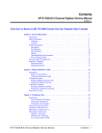
1. Connect the equipment as shown in Figure 4-1.
Figure 4-1. DC Voltage (Zero Volt Input) Setup
2. Set the HP E1411 multimeter as follows:
•
•
•
•
NOTE
Reset Multimeter ..................................................*RST
Auto Zero .................................................................ON
Power Line Cycles (PLC) ............................................1
Line Freq Reference (CAL:LFR) ...... 50Hz or 60Hz
*RST sets Auto Zero to ON and Power Line Cycles to 1.
Test Procedure
22
Verification Tests
Chapter 4
1. Set the HP E1411 range to 0.113 V (0.125 V with 10% over- range)
measure the input voltage with MEAS:VOLT:DC? 0.1
and
2. Observe the input, record the results on the Performance Test
and verify the results are within specified limits (at the
range selected for 1 PLC).
Record,
3. Repeat steps 1 and 2 for the following ranges:
E1411 Range
0.91 V
7.27 V
58.10 V
300.00 V
10% Overrange
1V
8V
64 V
None
Input
0V
0V
0V
0V
4. Remove power and disconnect test equipment.
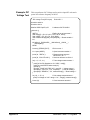
Example: Zero Volt
DCV Test
This example performs a DCV test for zero volts input and a power line
reference frequency of 60 Hz. Change line 20 to OUTPUT
70903;"CAL:LFR 50" for 50 Hz operation.
1
!Zero Volts Performance Verification
10
OUTPUT 70903;"*RST"
!Resets and sets autozero ON
and PLC to 1
20
OUTPUT 70903;"CAL:LFR 60"
!Sets line reference to 60 Hz
30
OUTPUT 70903;"MEAS:VOLT:DC? .1"
!Measure 0.113 V range
40
ENTER 70903;A
50
PRINT A
60
OUTPUT 70903;"MEAS:VOLT:DC? .9"
70
ENTER 70903;B
80
PRINT B
90
OUTPUT 70903;"MEAS:VOLT:DC? 7"
!Measure 0.91 V range
!Measure 7.27 V range
100 ENTER 70903;C
110 PRINT C
120 OUTPUT 70903;"MEAS:VOLT:DC? 58" !Measure 58.1 V range
130 ENTER 70903;D
140 PRINT D
150 OUTPUT 70903;"MEAS:VOLT:DC? 300" !Measure 300 V range
160 ENTER 70903;E
170 PRINT E
180 END
Chapter 4
Verification Tests
23
Test 4-2: DC Voltage Test (DCV Input)
This test verifies DC Voltage accuracy on all five ranges with DC voltage
inputs.
Equipment Setup
WARNING
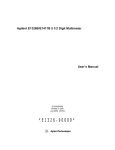
1. Connect the equipment as shown in Figure 4-2.
The DC Standard (Datron 4708, Option 10) can produce
dangerous voltages which are present on the terminals. Do not
touch the front (or rear) panel terminals unless you are sure no
dangerous voltage is present.
Figure 4-2. DC Voltage (DCV Input) Setup
2. Set the HP E1411 multimeter as follows:
•
•
•
•
24
Verification Tests
Reset Multimeter .................................................*RST
Auto Zero ................................................................ON
Power Line Cycles (PLC) ...........................................1
Line Freq Reference (CAL:LFR) ..... 50Hz or 60Hz
Chapter 4
NOTE
*RST sets Auto Zero to ON and Power Line Cycles to 1.
Test Procedure
1. Set the DC Standard Output to 0.1 DCV.
2. Set the HP E1411 range to 0.113 V (0.125 V with 10% overrange)
CONF:VOLT:DC .1
with
3. Measure the input with READ? and verify the results are within
specified limits (at the range selected for 1 PLC). Record results
on Performance Test Record.
4. Repeat steps 1 through 3 for the following DC Standard voltage
and HP E1411 ranges:
settings
E1411 Range
0.91 V
7.27 V
58.10 V
300.00 V
10% overrange
1V
8V
64 V
None
DC Std Output
0.9 V
7.0 V
58.0 V
300.0 V
5. Remove power and disconnect test equipment.
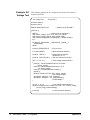
Example: DC Voltage
Test (DCV Input)
NOTE
Chapter 4
This example performs a DCV test for DC volts input and a power line
reference frequency of 60 Hz. Change line 80 to OUTPUT
70903;"CAL:LFR 50" for 50 Hz operation.
When connected to the HP E1411 multimeter, some DC Standards may
exhibit voltage variations at the start of a measurement. The WAIT 1
statement (line 150) provides a one second wait before measurement to
allow settling of the DC Standard output.
1
!DC Voltage Performance Verification
10
OPTION BASE 1
20
DIM Range(5), Volts(5), Read_meas(5)
30
DATA 0.113, 0.91, 7.27, 58.1, 300.0
40
READ Range(*)
50
DATA 0.1, 0.9, 7.0, 58.0, 300.0
60
READ Volts(*)
70
OUTPUT 70903;"*RST"
!Set autozero on and PLC 1
80
OUTPUT 70903;"CAL:LFR 60"
!Set 60 Hz line frequency
Verification Tests
25
90
FOR I=1 TO 5
100
PRINT "Set DC Standard to ";Volts(I);"VDC"
110
PRINT "Press Continue when ready"
120
PAUSE
130
CLEAR SCREEN
140
OUTPUT 70903;"CONF:VOLT:DC";Range(I) !Set DCV, range
150
WAIT 1
160
OUTPUT 70903;"READ?"
170
ENTER 70903;Read_meas(I)
!Wait for settling
!Enter DC voltage
180 NEXT I
190 FOR I=1 TO 5
200
PRINT "Voltage on";Range(I);"V range =";Read_meas(I);"VDC"
210 NEXT I
220 END
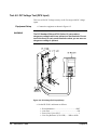
Test 4-3: AC Voltage Test
This test verifies AC voltage accuracy on the 87.5 mV and 300 V ranges
using sine wave inputs at ≥50% of full scale. The input frequency varies
from 20 Hz to 10 kHz. The DC component must be <10% of the AC
component.
NOTE
Equipment Setup
WARNING
26
Verification Tests
The DC Voltage Performance test must be performed prior to the AC
Voltage test to check the A/D accuracy on all ranges. If the DC Voltage test
has not been performed, the AC voltage must be checked on all ranges.
1. Connect the equipment as shown in Figure 4-3.
The AC Standard (Datron 4708, Option 20) can produce
dangerous voltages which are present on the terminals. Do not
touch the front (or rear) panel terminals unless you are sure no
dangerous voltage is present.
Chapter 4
Figure 4-3. AC Voltage Setup
2. Set the HP E1411 multimeter as follows:
•
•
•
•
NOTE
Reset Multimeter ..................................................*RST
Auto Zero ................................................................ON
Power Line Cycles (PLC) ...........................................1
Line Freq Reference (CAL:LFR) ..... 50Hz or 60Hz
*RST sets Auto Zero to ON and Power Line Cycles to 1.
Test Procedure
1. Set the AC Standard Output to 0.07 Vac at 20 Hz sine wave.
2. Set the HP E1411 range to 79.5 mV (87.5 mV with 10% overrange)
using CONF:VOLT:AC .07.
3. Measure the AC input voltage with READ? and verify the
results are within specified limits (at the range selected for 1 PLC).
Record the results on the Performance Test Record.
4. Repeat steps 1 through 3 using the following AC Standard
voltage and frequency settings, and HP E1411 ranges:
Chapter 4
Verification Tests
27
E1411
Range
10%
overrange
AC Standard Output
Voltage (Vac)
79.5 mV
79.5 mV
79.5 mV
300.0 V
87.5 mV
87.5 mV
87.5 mV
None
0.07 V
0.07 V
0.07 V
300.00 V
Frequency (Hz)
60 Hz
5 kHz
10 kHz
5 kHz
5. Remove power and disconnect test equipment.
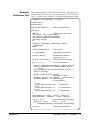
Example: AC Voltage
Test
NOTE
This example performs an ACV test for a power line reference frequency of
60 Hz. Change line 80 to OUTPUT 70903;"CAL:LFR 50" for 50 Hz
operation.
When connected to the HP E1411 multimeter, some AC Standards may
exhibit voltage variations at the start of a measurement. The WAIT 1
statement (line 160) allows settling for the AC Standard output.
1
! AC Voltage Performance Verification
10 OPTION BASE 1
20 DIM Read_meas(5),Source_volts(5),Source_freq(5)
30 DATA 0.07, 0.07, 0.07, 0.07, 300.0
40 READ Source_volts(*)
50 DATA 20, 60, 5000, 10000, 5000
60 READ Source_freq(*)
70 OUTPUT 70903;"*RST"
!Set autozero ON, PLC 1
80 OUTPUT 70903;"CAL:LFR 60"
!Set 60 Hz line ref frequency
90
FOR I=1 TO 5
100
PRINT "1. Set AC Standard output to";Source_volts(I);"Vac"
110
PRINT "2. Set AC Standard frequency to";Source_freq(I);"Hz"
120
PRINT "3. Press Continue when ready"
130
PAUSE
140
CLEAR SCREEN
150
OUTPUT 70903;"CONF:VOLT:AC";Source_volts(I)
160
WAIT 1
170
OUTPUT 70903;"READ?"
180
ENTER 70903;Read_meas(I)
!One second settling time
190 NEXT I
200 FOR I=1 TO 5
210 PRINT "Voltage for";Source_volts(I);"Vac range @";Source_freq(I);
"Hz=";Read_meas(I);"Vac"
220 NEXT I
28
Verification Tests
Chapter 4
230 END
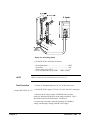
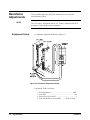
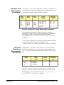
Test 4-4: Resistance Test (4-Wire Ohms)
This test verifies the 4-wire resistance accuracy of the 2kΩ, 100kΩ, and
1MΩ ranges.
NOTE
The DC Voltage performance test must be performed prior to the Resistance
Test to check the A/D accuracy on all ranges. If the DC Voltage test has not
been performed, resistance must be checked on all ranges at 0 and at 50%
of full scale.
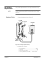
Figure 4-4. Resistance Test Setup
Equipment Setup
1. Connect the equipment as shown in Figure 4-4
2. Set the HP E1411 multimeter as follows:
• Reset Multimeter ..................................................*RST
• Auto Zero ..................................................................ON
• Power Line Cycles (PLC) .............................................1
Chapter 4
Verification Tests
29
• Line Freq Reference (CAL:LFR) ....50 Hz or 60 Hz
NOTE
Test Procedure
*RST sets Auto Zero to ON and Power Line Cycles to 1.
1. Set the Resistance Standard to 1 kΩ setting
2. Set the HP E1411 range to 1861Ω (2048Ω with 10% overrange)
with CONF:FRES 1861
3. Measure the input resistance with READ? and verify the results
are within specified limits (at the range selected for 1 PLC). Record
the results on the Performance Test Record.
NOTE
For best measurement accuracy, you may want to measure the ACTUAL
Resistance Standard value. You can do this by recording the front panel
display of the resistance value, or measuring the resistance with an HP
3458A multimeter or equivalent.
For example, suppose the ACTUAL resistance value for the 1 kΩ setting is
1001.3Ω. Then, the Lower Limit for this value = 1001.03 Ω and the Upper
Limit = 1001.57Ω. These limits would replace the existing limits of
999.730Ω and 1000.270Ω shown in Table 4-1. If the measured value falls
within the revised limits, the test passes.
4. Repeat steps 1 through 3 using the following Resistance Standard
settings:
E1411 Range
119,156 Ω
1,048,576 Ω
10%
overrange
131,052 Ω
N/A
Resistance
Std Setting
100 kΩ
1 MΩ
5. Remove power and disconnect test equipment.
30
Verification Tests
Chapter 4
Example: 4-Wire Ohms
Test
This example performs a 4-wire ohms resistance test for a power line
reference frequency of 60 Hz. Change line 80 to OUTPUT
70903;"CAL:LFR 50" for 50 Hz operation.
The program also calculates the Upper Limit and Lower Limit values for
ACTUAL Resistance Standard resistance value (lines 170-190). If the
actual Resistance Standard value is different than 1kΩ, 100kΩ, or 1MΩ,
replace the Lower Limit and Upper Limit values shown in Table 4-1,
Performance Test Record for the HP E1411 Multimeter, with the values
computed by the program.
1
!4-Wire Ohms Performance Verification
10 OPTION BASE 1
20 DIM Range(3),Source(3),Read_meas(3),Limit(3),Ohms(3)
30 DATA 1861, 119156, 1048576
40 READ Range(*)
50 DATA 1000, 100000, 1000000
60 READ Source(*)
70 OUTPUT 70903;"*RST"
!Set autozero on and PLC 1
80 OUTPUT 70903;"CAL:LFR 60"
!Set 60 Hz line ref frequency
90 FOR I=1 TO 3
100
PRINT "1. Set Resistance Standard to";Source(I);"Ohms"
110
PRINT "2. Measure ACTUAL Resistance Standard value (in Ohms)"
120
PRINT "Enter ACTUAL Resistance Standard value (in
Ohms)",Ohms(I)
130
CLEAR SCREEN
140
OUTPUT 70903;"CONF;FRES";Range(I)!Set 4-wire ohms, range
150
OUTPUT 70903;"READ?"
160
ENTER 70903;Read_meas(I)
170
IF I=1 THEN Limit(I)=.00025*Ohms(I)+2.0E-2 !2 kOhm limits
180
IF I=2 THEN Limit(I)=.00025*Ohms(I)+1
!131 kOhm limits
190
IF I=3 THEN Limit(I)=.00025*Ohms(I)+10
!1 MOhm limits
200 NEXT I
210 PRINT "Measured
Source
220 PRINT "Resistance
Resistance
Low Limit
High Limit"
(Ohms)
(Ohms)"
230 PRINT
240 Format:IMAGE 7D.3D,6X,7D.3D,6X,7D.3D,6X,7D.3D
250 FOR I=1 TO 3
260
PRINT USING Format;Read_meas(I),Ohms(I),Ohms(I)-Limit(I),
Ohms(I)+Limit(I)
270 NEXT I
280 END
Chapter 4
Verification Tests
31
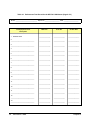
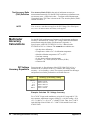
Performance
Test Record
NOTE
Multimeter
Accuracy
32
Table 4-1, Performance Test Record for the HP E1411 Multimeter, is a
form you can copy and use to record performance verification test results
for the multimeter. Page 3 of Table 4-1 shows multimeter accuracy,
measurement uncertainty and test accuracy ratio (TAR) values. See
Appendix A - Calculating Multimeter Accuracy for example calculations of
Table 4-1 entries.
The accuracy, measurement uncertainty, and TAR values shown in Table
4-1 are valid ONLY for the specific test conditions, test equipment, and
assumptions described. If you use different test equipment and/or change
the test conditions, you will need to compute the specific values for your test
setup.
Accuracy is defined for DC Voltage, AC Voltage, and 4-Wire Resistance
measurements using the 90-day specifications in Appendix A Specifications in the HP E1326A/E1411A User’s Manual or the
E1326B/E1411B User’s Manual. In Table 4-1, the "High Limit" and "Low
Limit" columns represent the multimeter accuracy for the specified test
conditions.
Measurement
Uncertainty
For the performance verification tests in this manual, measurement
uncertainties are calculated assuming a Datron 4708 source for inputs to the
multimeter. Measurement uncertainties in Table 4-1 are calculated for the
90-day accuracy specifications in the Datron 4708 User’s Handbook.
Test Accuracy
Ratio (TAR)
In Table 4-1, the "Test Accuracy Ratio (TAR)" is calculated from (high
limit - expected measurement)/measurement uncertainty. "N/A" means
measurement uncertainty and TAR do not apply to the measurement. If the
TAR value is <10:1, the TAR value is listed. If the TAR value is >10:1, the
entry is >10:1.
Verification Tests
Chapter 4
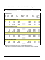
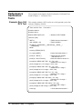
Table 4-1. Performance Test Record for the HP E1411 Multimeter (Page 1 of 3)
Test Facility:
Name
_________________________________________
Report No.
_____________________________________
Address
________________________________________
Date
___________________________________________
City/State
_______________________________________
Customer
______________________________________
Phone
_________________________________________
Tested by
_____________________________________
Model
________________________________________
Ambient temperature
__________________________oC
Serial No.
______________________________________
Relative humidity
_______________________________%
Options
_______________________________________
Line frequency _______________________ Hz
(nominal)
Firmware Rev.
__________________________________
Special Notes:
____________________________________________________________________________________________
____________________________________________________________________________________________
____________________________________________________________________________________________
____________________________________________________________________________________________
____________________________________________________________________________________________
____________________________________________________________________________________________
____________________________________________________________________________________________
____________________________________________________________________________________________
____________________________________________________________________________________________
____________________________________________________________________________________________
____________________________________________________________________________________________
_____________________________________________________________________________________________
Chapter 4
Verification Tests
33
Table 4-1. Performance Test Record for the HP E1411 Multimeter (Page 2 of 3)
Model _____________________________ Report No. ____________________ Date ____________________
Test Equipment Used:
Description
Model No.
Trace No.
Cal Due Date
1. DATRON 4708
_______________
_______________
_______________
2.
________________________________
_______________
_______________
_______________
3.
________________________________
_______________
_______________
_______________
4.
________________________________
_______________
_______________
_______________
5.
________________________________
_______________
_______________
_______________
6.
________________________________
_______________
_______________
_______________
7.
________________________________
_______________
_______________
_______________
8.
________________________________
_______________
_______________
_______________
9.
________________________________
_______________
_______________
_______________
10.
________________________________
_______________
_______________
_______________
11.
________________________________
_______________
_______________
_______________
12.
________________________________
_______________
_______________
_______________
11.
________________________________
_______________
_______________
_______________
12.
________________________________
_______________
_______________
_______________
13.
________________________________
_______________
_______________
_______________
34
Verification Tests
Chapter 4
Table 4-1. Performance Test Record for the HP E1411 Multimeter (Page 3 of 3)
Model ____________________________
Report No. ____________________________ Date_________________
90 day Specifications
Test
No.
Test
Input
DMM
Range
Low
Limit
Measured
Reading
High
Limit
Meas
Uncert*
Test Acc
Ratio
(TAR)**
DC Voltage (Zero Volts Input) (Values in V)
4-1
0.0
0.0
0.0
0.0
0.0
0.113
0.910
7.270
58.100
300.000
-.000005
-.000015
-.000050
-.001000
-.005000
__________
__________
__________
__________
__________
+.000005
+.000015
+.000050
+.001000
+.005000
N/A
N/A
N/A
N/A
N/A
N/A
N/A
N/A
N/A
N/A
.099972
.899868
6.999250
57.990300
299.950000
__________
__________
__________
__________
__________
.100028
.900132
7.000750
58.009799
300.050000
.0000012
.0000044
.0000210
.0002820
.0017750
>10:1
>10:1
>10:1
>10:1
>10:1
DC Voltage (DCV Input) (Values in VDC)
4-2
0.1
0.9
7.0
58.0
300.0
0.113
0.910
7.270
58.100
300.000
AC Voltage (20 Hz, 60 Hz, 10 kHz, 5 kHz) (Values in VAC)
4-3
0.07
0.07
0.07
0.07
300.00
0.0875
0.0875
0.0875
0.0875
300.00
.067480
.069327
.069327
.067578
296.125000
__________
__________
__________
__________
__________
.072523
.070673
.070673
.072423
303.875000
.000020
.000016
.000016
.000016
.047000
>10:1
>10:1
>10:1
>10:1
>10:1
999.730
99974.000
999740.000
__________
__________
__________
1000.270
100026.000
1000260.000
0.008
0.900
22.000
>10:1
>10:1
>10:1
4-Wire Resistance (Values in Ohms)
4-4
1000
100000
1000000
2000
131000
1000000
o
o
* Measurement Uncertainty of Datron 4708 source for 90 days since calibration and 23 C ±1 C.
** TAR = multimeter accuracy/measurement uncertainty, rounded to nearest integer for <10:1 and >10:1 otherwise.
Chapter 4
Verification Tests
35
Notes
36
Verification Tests
Chapter 4
Chapter 5
Adjustments
Introduction
This chapter contains procedures to adjust the HP E1411 multimeter for
peak performance. For best performance, the instrument should be adjusted
after repair. All adjustments are performed electrically, so manual
adjustment of the multimeter is not necessary.
WARNING
Do not perform any of the following adjustments unless you are
a qualified, service-trained person, and have read the
WARNINGS and CAUTIONS in Chapter 1 - General Information.
NOTE
Adjustment
Conditions /
Procedures
ALL adjustment procedures MUST be performed in the order shown in this
manual (DC Voltage, then AC Voltage, and then Resistance).
For valid adjustments, the HP E1411 multimeter and test equipment used
must have at least a 60 minute warm-up, and the line voltage must be
115/230 Vac ±10%. For best accuracy, the temperature of the area where
adjustments are made should be between 18oC and 28oC and stable to
within ±1oC. See Table 1-1, Recommended Test Equipment, for test
equipment requirements.
The adjustment procedures assume the person performing the adjustments
understands how to operate the mainframe, multimeter and specified test
equipment. The adjustment procedures do not specify test equipment
settings, except in general terms. It is assumed a qualified, service-trained
person will select and connect the cables and jumpers required for the
adjustments.
Chapter 5
Adjustments
37
DC Voltage
Adjustments
Equipment Setup
WARNING
This procedure adjusts HP E1411 multimeter DC voltage measurement
accuracy.
1. Connect the equipment as shown in Figure 5-1.
The DC Standard (Datron 4708, Option 10) can produce
dangerous voltages which are present on the terminals. Do not
touch the front (or rear) panel terminals unless you are sure no
dangerous voltage is present.
2. Set the HP E1411 as follows:
Figure 5-1. DC Voltage Adjustment Setup
• Reset Multimeter ......................................................*RST
• Auto Zero ......................................................................ON
• Power Line Cycles (PLC) .................................................1
• Line Freq Reference (CAL:LFR ) ....... 50 Hz or 60 Hz
38
Adjustments
Chapter 5
NOTE
Adjustment
Procedure
*RST sets Auto Zero to ON and Power Line Cycles to 1.
1. Set the DC Standard output to 7.7 V
2. Set the HP E1411 range to 8 V, and adjust the multimeter
at 7.7 V using:
FUNC:VOLT:DC
VOLT:DC:RANG 8
CAL:VAL 7.7
TRIG:DEL .05
CAL?
3. Verify that the returned calibration error code is 0 (no error).
If not 0, see Table 5-1 for a list of calibration errors and codes.
The calibration error can be returned to an external computer
using an ENTER type statement.
4. Repeat steps 1 through 3 using the following HP E1411
voltage ranges and DC Standard settings:
HP E1411 range
8V
0.125 V
0.125 V
1V
1V
64 V
64 V
300 V
300 V
DC Standard Output
-7.7 V
+0.121 V
- 0.121 V
+0.97 V
- 0.97 V
+62 V
-62 V
+300 V
-300 V
5. Remove power and disconnect test equipment.
Example: DC
Voltage
Adjustments
This example performs DC voltage adjustments for a power line reference
frequency of 60 Hz. Change line 80 to OUTPUT 70903;"CAL:LFR 50" for
50 Hz operation.
If no calibration error occurs (Cal_code = 0 in line 210), the program
displays an "adjustment complete" message. If a calibration error occurs,
the program displays the calibration error and prompts you to repeat the
adjustment (see Table 5-1 for a list of calibration errors).
Chapter 5
Adjustments
39
When connected to the HP E1411 multimeter, some DC Standards may
exhibit voltage variations at the start of a measurement. TRIG:DEL .05 (line
190) adds a 0.8 sec wait before calibration begins to allow settling time for
the DC Standard output. TRIG:DEL .05 is used since the input is sampled
16 times before the calibration is performed. Thus, total delay added = 0.05
seconds x 16 = 0.8 seconds.
1
! DC Voltage Adjustments
10
OPTION BASE 1
20
DIM Range(10),Volts(10)
30
DATA 8.0, 8.0, 0.125, 0.125, 1.0, 1.0, 64.0, 64.0, 300.0, 300.0
40
READ Range(*)
50
DATA 7.7, -7.7, .121, -.121, .97, -.97, 62.0, -62.0, 300.0, -300.0
60
READ Volts(*)
70
OUTPUT 70903;"*RST"
!Set autozero on and PLC 1
80
OUTPUT 70903;"CAL:LFR 60"
!Set 60 Hz line ref frequency
90
FOR I=1 TO 10
100 Re_try: !
110
120
PRINT "Set DC Standard to";Volts(I);"VDC"
130
PRINT "Press Continue when ready"
140
PAUSE
150
CLEAR SCREEN
160
OUTPUT 70903;"FUNC:VOLT:DC"
OUTPUT 70903;"VOLT:RANG ";Range(I) !Set E1411 range
180
OUTPUT 70903;"CAL:VAL";Volts(I)
!Set CAL:VAL value
190
OUTPUT 70903;"TRIG:DEL .05"
!Wait for settling
200
OUTPUT 70903;"CAL?"
!Perform calibration
210
ENTER 70903 USING "K";Cal_code !Return cal error code
220
IF Cal_code <>0 THEN
230
PRINT "Calibration Error";Cal_code;"for ";Volts(I);"VDC input."
240
PRINT "Check source value/connections, then"
250
PRINT "press Continue to retry this adjustment"
260
PAUSE
270
GOTO Re_try
290
Adjustments
!Set DCV function
170
280
40
CLEAR SCREEN
ELSE
PRINT "Adjustment complete for";Volts(I);"VDC input"
300
END IF
310
PRINT "Press Continue for the next adjustment"
320
PAUSE
330
CLEAR SCREEN
340
NEXT I
350
END
Chapter 5
AC Voltage
Adjustments
NOTE
Equipment Setup
This procedure adjusts the HP E1411 AC voltage measurement accuracy.
The DC Voltage adjustment MUST be performed before the AC Voltage
adjustment.
1. Connect the equipment as shown in Figure 5-2
Figure 5-2. AC Voltage Adjustment Setup
2. Set the HP E1411 as follows:
•
•
•
•
Chapter 5
Reset Multimeter ....................................................*RST
Auto Zero .................................................................... ON
Power Line Cycles (PLC) .............................................. 1
Line Freq Reference (CAL:LFR ) ...... 50 Hz or 60 Hz
Adjustments
41
NOTE
Adjustment
Procedure
*RST sets Auto Zero to ON and Power Line Cycles to 1.
1. Set the AC Standard output to 5.6 Vac at 1 kHz
2. Set the HP E1411 range to 5.6 V, and adjust the multimeter
at 5.6 V using:
FUNC:VOLT:AC
VOLT:AC:RANG 5.6
CAL:VAL 5.6
TRIG:DEL .05
CAL?
3. Verify that the returned calibration error code is 0 (no error).
If not 0, see Table 5-1 for a list of calibration errors and codes.
4. Remove power and disconnect test equipment
Example: AC Voltage
Adjustments
This example performs an AC voltage adjustment for a power line reference
frequency of 60 Hz. Change line 20 to OUTPUT 70903;"CAL:LFR 50" for
50 Hz operation.
If no calibration error occurs (Cal_code = 0 in line 130), the program
displays an "adjustment complete" message. If a calibration error occurs,
the program displays the calibration error (see Table 5-1 for a list of
calibration errors).
When connected to the HP E1411 multimeter, some AC Standards may
exhibit voltage variations at the start of a measurement. TRIG:DEL .05 (line
110) adds a 0.8 sec wait before calibration begins to allow settling time for
the AC Standard output. TRIG:DEL .05 is used since the input is sampled
16 times before the calibration is performed. Thus, total delay added = 0.05
seconds x 16 = 0.8 seconds.
42
Adjustments
Chapter 5
1
! AC Voltage Adjustments
10 OUTPUT 70903;"*RST"
!Set autozero on and PLC 1
20 OUTPUT 70903;"CAL:LFR 60"
!Set 60 Hz line ref frequency
30 Re_try: !
40 PRINT "Set AC Standard to 5.6 Vac at 1.0 kHz"
50 PRINT "Press Continue when ready"
60 PAUSE
70 CLEAR SCREEN
80 OUTPUT 70903;"FUNC:VOLT:AC"
!Set ACV function
90 OUTPUT 70903;"VOLT:RANG 5.6"
!Set 5.6 Vac range
100 OUTPUT 70903;"CAL:VAL 5.6"
!Set 5.6 Vac cal value
110 OUTPUT 70903;"TRIG:DEL .05"
!Wait for settling
120 OUTPUT 70903;"CAL?"
!Perform calibration
130 ENTER 70903 USING "K";Cal_code
140 IF Cal_code <> 0 THEN
150
PRINT "Calibration Error";Cal_code;"on 5.6 Vac range"
160
PRINT "Check source value/connections, then"
170
PRINT "press Continue to retry this adjustment"
180
PAUSE
190
CLEAR SCREEN
200
GOTO Re_try
210 ELSE
220
PRINT "AC Voltage adjustment complete"
230 END IF
240 END
Chapter 5
Adjustments
43
Resistance
Adjustments
NOTE
Equipment Setup
This procedure adjusts the HP E1411 multimeter 4-wire resistance
measurement accuracy.
The DC Voltage adjustment and the AC Voltage adjustment MUST be
performed before the Resistance adjustment.
1. Connect the equipment as shown in Figure 5-3
Figure 5-3. Resistance Adjustments Setup
2. Set the HP E1411 as follows:
•
•
•
•
44
Adjustments
Reset Multimeter .................................................... *RST
Auto Zero ................................................................... ON
Power Line Cycles (PLC) .............................................. 1
Line Freq Reference (CAL:LFR) .......... 50 Hz or 60 Hz
Chapter 5
NOTE
Adjustment
Procedure
*RST sets Auto Zero to ON and Power Line Cycles to 1.
1. Set the Resistance Standard to 1 kΩ.
2. Set the HP E1411 range to 2 kΩ, and adjust the multimeter
at 1 kΩ using:
FUNC:FRES
FRES:RANG 2000
CAL:VAL 1000
CAL?
NOTE
For best adjustment accuracy, you may want to measure the ACTUAL
resistance value of the Resistance Standard and use the value in the
CAL:VAL command. You can read the actual resistance value from the
Datron front panel or you can measure the value with an HP 3458A
multimeter or equivalent.
3. Verify that the returned calibration error code is 0 (no error).
If not 0, see Table 5-1 for a list of calibration errors and codes. The
calibration error can be returned to the external computer using
an ENTER type statement.
4. Repeat steps 1 through 3 using the following HP E1411
(and FRES:RANG) ranges, and Resistance Standard
(and CAL:VAL) values:
HP E1411 Range
16000 Ω
1000000 Ω
Resistance Standard
10000 Ω*
1000000 Ω*
* Or, use actual measured source resistance value
5. Remove power and disconnect test equipment.
Chapter 5
Adjustments
45
Example: 4-Wire
Resistance
Adjustments
This example performs a 4-wire ohms resistance adjustment for a power
line reference frequency of 60 Hz. Change line 80 to OUTPUT
70903;"CAL:LFR 50" for 50 Hz operation. If a calibration error occurs, the
program displays the calibration error and prompts you to repeat the
adjustment (see Table 5-1 for a list of calibration errors).
1
! 4-Wire Resistance Adjustments
10 OPTION BASE 1
20 DIM Range(3),Source(3)
30 DATA 2000, 16000, 1048576
40 READ Range(*)
50 DATA 1000, 10000, 1000000
60 READ Source(*)
70 OUTPUT 70903;"*RST"
!Set autozero on and PLC 1
80 OUTPUT 70903;"CAL:LFR 60"
!Set 60 Hz line ref frequency
90
FOR I=1 TO 3
100 Re_try: !
110
PRINT "1. Set Resistance Standard to";Source(I);"Ohms"
120
PRINT "2. Measure ACTUAL Resistance Standard value (in Ohms)"
130 PRINT "Enter ACTUAL Resistance Standard value (in
Ohms)",Ohms_actual
140
CLEAR SCREEN
150
OUTPUT 70903;"FUNC:FRES"
160
OUTPUT 70903;"FRES:RANG ";Range(I)!Set resistance range
170
OUTPUT 70903;"CAL:VAL";Ohms_actual(I)!Set cal value
180
OUTPUT 70903;"CAL?"
190
ENTER 70903;Cal_code
200
IF Cal_code <> 0 THEN
210
PRINT "Calibration Error";Cal_code;"with";Source(I);"Ohms input."
220
PRINT "Check source value/connections, then"
230
PRINT "Press Continue to repeat this adjustment"
240
PAUSE
250
CLEAR SCREEN
260
GOTO Re_try
!Set 4-wire ohms
!Perform calibration
270 ELSE
280
PRINT "Adjustment complete with";Source(I);"Ohms source"
290
PRINT "Press Continue for the next adjustment"
300
PAUSE
310
CLEAR SCREEN
320 END IF
330 NEXT I
340 PRINT "Resistance adjustments completed"
350 END
46
Adjustments
Chapter 5
Calibration
Errors
Table 5-1 summarizes calibration error numbers, titles and descriptions for
the HP E1411 multimeter. Note that an error is returned if the adjustment
(calibration) standard used is outside the calibration range of the multimeter
(between ±[0.5 full scale and full scale]).
Table 5-1. HP E1411 Multimeter Calibration Errors
Error
Title
Description
Code*
0
No Error
No error has occurred since last time the error code was read.
4
Reading
Overrun
The FIFO memory was still full at the time the new reading
was ready, or a new command was received while in the
middle of outputting a reading. TRIGGER ARM is disabled
and the multimeter waits for a new command.
U
6
Calibration
Error
An error occurred when computing a calibration constant,
probably due to an improper input or a defective Unit Under
Test (UUT). Calibration cycle aborted.
U/H
7
Checksum
Error
The non-volatile RAM contains a checksum error. The data is
assumed to be corrupted.
H
8
Invalid
CAL
Request
Calibration requested for an invalid combination of multimeter
range and function.
U
9
Bad CAL
Target
The target value for the calibration was outside the range of
±(0.5 full scale to full scale).
U
11
No
Inguard
Response
No response from inguard (expected data and got nothing).
Timed out instead.
H
13
Linearity
CAL Error
An error has occurred during a linearity calibration sequence.
Probably a hardware failure of the A/D inguard section.
H
14
Pacer
Overrun
Error
The pacer is in use and the pacer rate is faster than the
maximum A/D conversion rate based on integration time,
autorange setting, autozero setting, and interrupts enabled.
U
15
Input
Overload
A potentially damaging overload has been applied to the
multimeter terminals and the multimeter has disconnected
from the input. A new SET RANGE command is necessary to
restore normal operation. A damaging overload is defined as:
U
1. Applying >±40 volts Hl to LO or Hl to COMMON while in
manual range with RANGE ≤ 8 volts.
2. Applying >±40 volts between LO and COMMON under any
circumstances.
* U = improper operation, H = hardware failure
Chapter 5
Adjustments
47
Notes
48
Adjustments
Chapter 5
Chapter 6
Replaceable Parts
Introduction
Exchange
Assemblies
Tables 6-1 and 6-2 list assemblies that may be replaced on an exchange
basis (EXCHANGE ASSEMBLIES). Exchange, factory-repaired, and
tested assemblies are available only on a trade-in basis. Defective
assemblies must be returned for credit. Assemblies required for spare parts
stock must be ordered by the new assembly part number. Contact your
nearest Hewlett-Packard Sales and Support Office for details.
Ordering
Information
To order a part listed in Table 6-1 or 6-2, specify the Hewlett-Packard part
number and the quantity required. Send the order to your nearest
Hewlett-Packard Sales and Support Office.
Replaceable
Parts List
Chapter 6
This chapter contains information to order replaceable parts for the HP
E1411A and E1411B multimeters.
Table 6-1, HP E1411A Replaceable Parts, lists replaceable parts for the HP
E11411A multimeter. See Figure 6-1 (page 6-3) for locations of parts listed
in Table 6-1. Table 6-2, HP E1411B Replaceable Parts, lists replaceable
parts for the HP E11411B multimeter. See Figure 6-2 (page 6-5) for
locations of parts listed in Table 6-2.
Replaceable Parts
49
Table 6-1. HP E1411A Replaceable Parts
Reference*
Designator
HP Part
Number
Qty
Description
Mfr**
Code
Mfr Part Number
EXCHANGE ASSEMBLIES
E1411A Multimeter Module (New)
E1411A Multimeter Module (Exchange)
28480
28480
E1411-66201
E1411-69201
1
MULTIMETER PCA [a]
Fuse - Sub Miniature - 4A
Fuse - Sub Miniature - 4A
Connector - Right Angle BNC
Connector - Post 2 x 6
Connector - 4 Pin Right Angle
Connector - Header 16 Pin
Connector - Header 16 Pin
Relay - Reed
Relay - Reed
Relay - Reed
Connector - Right Angle - 96 Pin
Connector - Right Angle - 64 Pin
4-Position Jumper
Switch - Rocker 8 Position 5 V 0.1 A
Socket - 40 Pin Integrated Circuit
Socket - 40 Pin Integrated Circuit
Socket - 16 Pin Integrated Circuit
28480
75915
75915
24931
18873
27264
18873
18873
71707
71707
71707
06776
18873
18873
81073
00779
00779
00779
E1411-66501
R251004T1
R251004T1
28JR342-1
68668-004
705-53-0108
67997-616
67997-616
3500-0050
3500-0050
3500-0051
DIN96CPCSRITR
75882-364
69146-204
76YY22968S
2-640379-1
2-640379-1
2-640358-1
E1326-61601
E1326-61605
1
1
CABLE ASSEMBLIES
Cable Assembly - 6 Conductor
Cable Assembly - 4 Conductor
28480
28480
E1326-61601
E1326-61605
MP1
MP2
MP3
MP4
MP5
MP6
MP7
MP8
PNL1
SHD1
SHD2
E1400-84105
E1400-84106
1510-0091
1510-0091
1510-0091
1510-0091
8160-0686
1400-0249
E1411-00201
E1411-00602
E1411-00601
2
1
1
1
1
1
MECHANICAL PARTS
Handle Kit-Bottom
Handle Kit-Top
Binding Post - Red
Binding Post - Red
Binding Post - Red
Binding Post - Red
Clip-RFI Strip
Cable Tie - 0.062-0.625 IN DIA
Panel - Faceplate
Shield - Bottom
Shield - Top
28480
28480
28480
28480
28480
28480
30817
59730
28480
28480
28480
E1400-84105
E1400-84106
1510-0091
1510-0091
1510-0091
1510-0091
00786-185
TY-23M-8
E1411-00201
E1411-00602
E1411-00601
SCW1, SCW2
SCW3-SCW8,
SCW15
SCW 9-SCW11
SCW12-SCW13
HDW1-HDW4
HDW5-HDW8
0515-0368
0515-1135
0515-1375
0515-1968
2950-0001
3050-0593
2
7
3
2
4
4
COMMON HARDWARE
Screw Pan-Head M2.5 X 12 Torx T8
Screw Pan-Head M3 X 25 Torx T8
Screw Flat-Head M2.5 X 6 Torx T8
Screw Pan-Head M2.5 X 11 Pozidriv
Nut-Hex-DBL Chamfer 3/8 - 32 THD
Washer-Spring NO. 3/8
00000
00000
00000
00000
00000
00000
Order by Description
Order by Description
Order by Description
Order by Description
Order by Description
Order by Description
E1411-66201
E1411-69201
1
1
A1
A1F1
A1F2
A1J2
A1J102
A1J103
A1JM1
A1JM3
A1K104
A1K105
A1K106
A1P1
A1P2
A1P3
A1SP1
A1XU23
A1XU104
A1XU124
E1411-66501
2110-0712
2110-0712
1250-1846
1251-3712
1252-3416
1251-4927
1251-4927
0490-1556
0490-1556
0490-1555
1252-1596
1251-7892
1258-0247
3101-3066
1200-0817
1200-0817
1200-0853
1
2
CBL1
CBL2
1
1
1
2
2
1
1
1
1
1
2
4
* See Table 6-3 for Reference Designator definitions
** See Table 6-4 for Code List of Manufacturers
[a] Repair limited to replacement of parts listed - see Introduction for ordering information
50
Replaceable Parts
Chapter 6
Figure 6-1. HP E1411A Replaceable Parts
Chapter 6
Replaceable Parts
51
Table 6-2. HP E1411B Replaceable Parts
Reference*
Designator
HP Part
Number
Qty
Description
Mfr**
Code
Mfr Part Number
EXCHANGE ASSEMBLIES
E1411B Multimeter Module (New)
E1411B Multimeter Module (Exchange)
28480
28480
E1411-66511
E1411-69511
1
MULTIMETER PCA [a]
Fuse - Sub Miniature - 4A
Fuse - Sub Miniature - 4A
Connector - Right Angle BNC
Connector - Post 2 x 6
Connector - 4 Pin Right Angle
Connector - Right Angle BNC
Connector - Header 16 Pin
Connector - Header 16 Pin
Relay - Reed
Relay - Reed
Relay - Reed
Connector - Right Angle - 96 Pin
Connector - Right Angle - 64 Pin
4-Position Jumper
Switch - Rocker 8 Position 5 V 0.1 A
Socket - 40 Pin Integrated Circuit
Socket - 40 Pin Integrated Circuit
Socket - 16 Pin Integrated Circuit
28480
75915
75915
24931
18873
27264
24931
18873
18873
71707
71707
71707
06776
18873
18873
81073
00779
00779
00779
E1411-66511
R251004T1
R251004T1
28JR342-1
68668-004
705-53-0108
28JR342-1
67997-616
67997-616
3500-0050
3500-0050
3500-0051
DIN96CPCSRITR
75882-364
69146-204
76YY22968S
2-640379-1
2-640379-1
2-640358-1
E1326-61601
E1326-61605
1
1
CABLE ASSEMBLIES
Cable Assembly - 6 Conductor
Cable Assembly - 4 Conductor
28480
28480
E1326-61601
E1326-61605
MP1
MP2
MP3
MP4
MP5
MP6
MP7
MP8
PNL1
SHD1
SHD2
E1400-45102†
E1400-45101†
1510-0091
1510-0091
1510-0091
1510-0091
8160-0686
1400-0249
E1411-00202†
E1411-00612
E1411-00611
1
1
4
1
1
1
1
1
MECHANICAL PARTS
Handle Bottom Metal Injection
Handle Top Metal Injection
Binding Post - Red
Binding Post - Red
Binding Post - Red
Binding Post - Red
Clip-RFI Strip
Cable Tie - 0.062-0.625 IN DIA
Panel - Faceplate
Shield - Bottom
Shield - Top
28480
28480
28480
28480
28480
28480
30817
59730
28480
28480
28480
E1400-45102
E1400-45101
1510-0091
1510-0091
1510-0091
1510-0091
00786-185
TY-23M-8
E1411-00202
E1411-00602
E1411-00601
SCW1-SCW2
SCW3-SCW8,
SCW15
SCW11
HDW1-HDW4
HDW5-HDW8
E1400-00610†
0515-1135
0515-1375
2950-0001
3050-0593
2
7
1
4
4
COMMON HARDWARE
Shoulder Screw Assembly
Screw Pan-Head M3 X 25 Torx T8
Screw Flat-Head M2.5 X 6 Torx T8
Nut-Hex-DBL Chamfer 3/8 - 32 THD
Washer-Spring NO. 3/8
28480
00000
00000
00000
00000
E1400-00610
Order by Description
Order by Description
Order by Description
Order by Description
E1411-66511***
E1411-69511***
1
1
A1
A1F1
A1F2
A1J2
A1J102
A1J103
A1J301
A1JM1
A1JM3
A1K104
A1K105
A1K106
A1P1
A1P2
A1P3
A1SP1
A1XU23
A1XU104
A1XU124
E1411-66511
2110-0712
2110-0712
1250-1846
1251-3712
1252-3416
1250-1846
1251-4927
1251-4927
0490-1556
0490-1556
0490-1555
1252-1596
1251-7892
1258-0247
3101-3066
1200-0817
1200-0817
1200-0853
1
2
CBL1
CBL2
1
1
1
2
2
1
1
1
1
1
2
* See Table 6-3 for Reference Designator definitions
** See Table 6-4 for Code List of Manufacturers
*** PC Board Replacement only
[a] Repair limited to replacement of parts listed - see Introduction for ordering information
† These parts are not compatible with older versions of the E1411B that have plastic handles. To replace one of these parts o n an
older E1411B, you must order all four of the parts marked with a † and a new top shield.
52
Replaceable Parts
Chapter 6
Figure 6-2. HP E1411B Replaceable Parts
Chapter 6
Replaceable Parts
53
Table 6-3. HP E1411 Reference Designators
HP E1411 Reference Designators
A .......................................... assembly
CBL ............................................ cable
F ................................................... fuse
J ................ electrical connector (jack)
JM ........ electrical connector (header)
K ...................................................relay
MP .................. misc. mechanical part
P ............... electrical connector (plug)
PNL ............................................ panel
SHD ........................................... shield
SP ............................................. switch
XU ............... socket, integrated circuit
Table 6-4. HP E1411 Code List of Manufacturers
Mfr Code
00000
00779
06776
18873
24931
27264
28480
30817
59730
71707
75915
81073
54
Replaceable Parts
Manufacturer Name
Any satisfactory supplier
AMP INC
Robinson Nugent Inc
Dupont E I DE Nemours & Co
Specialty Connector Co
Molex Inc
Hewlett Packard Company
Instrument Specialties Co Inc
Thomas & Betts Corp
Coto Wabash
Littelfuse Inc
Grayhill Inc
Address
Harrisburg, PA 17111
New Albany, IN 47150
Wilmington, DE 19801
Franklin, IN 46131
Lisle, IL 60532
Palo Alto, CA 94304
Del Water Gap, PA 07424
Raritan, NJ 08869
Providence, RI 02907
Des Plaines, IL 60016
La Grange, IL 60525
Chapter 6
Chapter 7
Manual Changes
Introduction
Chapter 7
This chapter contains information to adapt this manual to instruments for
which the content does not directly apply. Since this manual applies directly
to instruments with serial numbers listed on the title page, change
information is not required. See Multimeter Serial Numbers in Chapter 1 General Information for HP E1411 multimeter serial number information.
Manual Changes
55
56
Manual Changes
Chapter 7
Chapter 8
Service
Introduction
WARNING
Equipment
Required
This chapter contains information to service the HP E1411 multimeter
including troubleshooting guidelines and repair/maintenance guidelines.
Do not perform any of the service procedures shown unless
you are a qualified, service-trained person, and have read the
WARNINGS and CAUTIONS in Chapter 1 - General Information.
Equipment required for multimeter troubleshooting and repair is listed in
Table 1-1, Recommended Test Equipment. Any equipment that satisfies the
Requirements in the table may be substituted. To avoid damage to the screw
head slots, use Pozidriv or Torx drivers as specified in the instructions.
Pozidriv and Torx drivers used are listed in Table 8-1.
Table 8-1. Pozidriv/Torx Drivers
Description
Service Aids
HP Part Number
No. 1 Pozidriv
No. 2 Pozidriv
8710-0899
8710-0900
Size T-8 Torx
Size T-10 Torx
Size T-15 Torx
8710-1673
8710-1284
8710-1816
There are no test points or manual adjustment locations for the HP E1411
multimeter. Service aids on printed circuit boards include pin numbers,
some reference designations, and assembly part numbers. See Chapter 6 Replaceable Parts for descriptions and location of HP E1411 replaceable
parts.
Service notes, manual updates, and service literature for the HP E1411
multimeter may be available through Hewlett-Packard. For information,
contact your nearest Hewlett-Packard Sales and Support Office.
Chapter 8
Service
57
Troubleshooting
Techniques
Identifying the
Problem
There are two main steps to troubleshoot an HP E1411 multimeter
problem: (1) identify the problem, and (2) test assemblies to isolate the
cause to a user-replaceable component.
Multimeter problems can be divided into four general categories:
•
•
•
•
Self-test errors
Operator errors
Catastrophic failures
Performance out of specification
Self-Test Errors
An error number (1, 2, 3, or 4) is returned when the multimeter self-test
fails. If a self-test error occurs, recycle power and repeat the self-test. If the
error repeats, see "Testing Assemblies" to troubleshoot the multimeter.
Table 8-2 shows some typical causes of self-test errors.
Table 8-2. Self-Test Errors
Error
Description
Typical Causes
1
Multimeter does not respond to
self-test
. Bad connections/settings
. Incorrect operation
. Hardware failure (exchange)
2
Invalid communication between A1
and A2 processors
. Bad A1/A2 communication
. Hardware failure (exchange)
3
Data line between multimeter and
mainframe failed
. Bad connections/settings
. Incorrect operation
. Hardware failure (exchange)
4
Invalid communication between
multimeter and mainframe
. Bad connections/settings
. Incorrect operation
. Hardware failure (exchange)
Operator Errors
Apparent failures may result from operator errors. See Appendix B - Error
Messages in the HP E1326A/E1411A User’s Manual or the
E1326B/E1411B User’s Manual for information on operator errors.
Catastrophic Failure
If a catastrophic failure occurs, see "Testing Assemblies" to troubleshoot the
multimeter.
58
Service
Chapter 8
Performance Out of Specification
If the multimeter performance is out of specification limits, use the
adjustment procedures in Chapter 5 - Adjustments to correct the problem. If
the condition repeats, see "Testing Assemblies" to troubleshoot the
multimeter.
Testing Assemblies
NOTE
You can use the tests and checks in Table 8-3 to isolate the problem to a
user-replaceable part on the multimeter frame or PCA. See Figure 6-1 (HP
E1411A) or Figure 6-2 (HP E1411B) in Chapter 6 - Replaceable Parts for
locations of user-replaceable parts.
If the problem cannot be traced to a user-replaceable part listed in Table
6-1 or Table 6-2, return the multimeter to Hewlett-Packard for exchange.
See Chapter 6 - Replaceable Parts for procedures.
Table 8-3. HP E1411 Tests/Checks
Test/Check
Reference Designator
Check:
Heat Damage
----------
Discolored PC boards
Damaged insulation
Evidence of arcing
Switch/Jumper
Settings
JM1, JM3, P3
SP1
IRQ Level setting
LADDR setting
Frame
CBL1, CBL2
MP3, MP4, MP5, MP6
Cable contact damage
Panel binding posts
A1 Printed
Circuit
Assembly
F1, F2
J2, J102, J103, J301
K104, K105, K106
P1,P2
XU23, XU104, XU124
Fuse continuity
Mating connector contacts
Relay opening/closure
Connector contacts
IC contact/connections
Checking Heat Damage
Inspect the multimeter for signs of abnormal internally generated heat such
as discolored printed circuit boards or components, damaged insulation, or
evidence of arcing. If there is damage, do not operate
the multimeter until you correct the problem.
Chapter 8
Service
59
Checking Switches/Jumpers
Verify the logical address setting is set correctly (factory set at 24). Verify
the interrupt priority jumpers are set correctly (factory set at level 1). See
the HP E1326A/E1411A User’s Manual or the E1326B/E1411B User’s
Manual for information.
Testing Multimeter Frame
To test the multimeter frame, see Table 8-3 for guidelines to check binding
posts MP3, MP4, MP5, and MP6, and cables CBL1 and CBL2. If you need
to remove and/or replace the binding posts, see "Removing Binding Posts"
in this chapter.
Testing Printed Circuit Assembly
To test the PCA, remove mainframe power and remove the multimeter from
the mainframe. Next, remove the Top Shield (see "Removing Top Shield"
for instructions). Then, see Table 8-3 for guidelines to isolate the problem to
a user-replaceable part.
Repair
Guidelines
ESD Precautions
This section gives guidelines to repair the HP E1411 multimeter, including:
•
•
•
•
•
•
ESD precautions
Removing top shield
Removing front panel/bottom shield
Removing binding posts
Soldering printed circuit boards
Post-repair safety checks
Electrostatic discharge (ESD) may damage MOS, CMOS and other
static-sensitive devices in the HP E1411 multimeter. This damage can range
from slight parameter degradation to catastrophic failure. When handling
multimeter assemblies, follow these guidelines to avoid damaging
multimeter components:
• Always use a static-free work station with a pad of conductive
rubber or similar material when handling multimeter components.
• After you remove an assembly from the multimeter, place the
assembly on a conductive surface to guard against ESD damage. Do
not stack assemblies.
60
Service
Chapter 8
• Do not use pliers to remove a MOS or CMOS device from a
high-grip socket. Instead, use a small screwdriver to pry the device
up from one end. Slowly lift the device up, one pair of pins at a time.
• After you remove a MOS or CMOS device from an assembly, place
the device onto a pad of conductive foam or other suitable holding
material.
• If a device requires soldering, be sure the assembly is placed on a
pad of conductive material. Also, be sure you, the pad, and the
soldering iron tip are grounded to the assembly. Apply as little heat
as possible when soldering.
Removing Top
Shield
Use the following steps to remove the top shield from the printed circuit
assembly (PCA). See Figure 8-1 for component locations.
1.
2.
3.
4.
Remove seven Torx T8 screws
Lift top shield from the back until front slots can be
disengaged from tabs.
Remove the top shield.
Reverse steps 1 through 3 to replace top shield.
Figure 8-1. Removing Top Shield
Chapter 8
Service
61
NOTE
Removing Front
Panel
When reinstalling the top shield, verify that the slots are aligned with the
tabs, then set the top shield into place.
Use the following steps to remove the front panel and bottom shield from
the printed circuit assembly (PCA). See Figure 8-2 for component locations.
1.
2.
3.
4.
5.
Remove Torx T8 screw from front panel
Remove two Torx T8 screws from PCA
Remove cable assembly from clip
Slide PCA off bottom shield
Reverse steps 1 through 4 to replace front panel and
bottom shield
Figure 8-2. Removing Front Panel
62
Service
Chapter 8
Removing Binding
Posts
Use the following steps to remove the HP E1411 front panel binding posts
(MP3, MP4, MP5, and MP6) (see Figure 8-3).
1.
2.
3.
4.
Unsolder wire
Remove the 3/8-32 nut and spring washer
Remove the binding post
Reverse the order to reinstall the binding posts
Figure 8-3. Removing Binding Posts
Soldering Printed
Circuit Boards
CAUTION
Chapter 8
The etched circuit boards in the multimeter have plated-through holes that
allow a solder path to both sides of the insulating material. Soldering can be
done from either side of the board with equally good results. When
soldering to any circuit board, keep in mind the following guidelines:
Do not use a sharp metal object such as an awl or twist drill, since
sharp objects may damage the plated-through conductor.
Service
63
• Avoid unnecessary component unsoldering and soldering. Excessive
replacement can result in damage to the circuit board and/or
adjacent components.
• Do not use a high power soldering iron on etched circuit boards as
excessive heat may lift a conductor or damage the board.
• Use a suction device or wooden toothpick to remove solder from
component mounting holes. When using a suction device, be sure
the equipment is properly grounded to prevent electrostatic
discharge from damaging CMOS devices.
Post-Repair Safety
Checks
64
Service
After making repairs to the HP E1411 multimeter, inspect the multimeter
for any signs of abnormal internally generated heat, such as discolored
printed circuit boards or components, damaged insulation, or evidence of
arcing. Determine and correct the cause of the condition. Then run the
self-test (*TST? command) to verify that the multimeter is functional.
Chapter 8
Appendix A
Calculating Multimeter Accuracy
Introduction
This appendix shows how multimeter accuracy, measurement uncertainty,
and test accuracy ratio (TAR) values are defined and calculated for the
performance verification tests for the HP E1411 multimeter.
See Table 4-1, "Performance Test Record for the HP E1411 Multimeter" for
90-day specification values of multimeter accuracy, measurement
uncertainty, and test accuracy ratios (TARs).
NOTE
Multimeter accuracy, measurement uncertainty, and test accuracy ratios in
Table 4-1 are valid ONLY for the specified test conditions and assumptions
described in this manual. For the test conditions described, all TARs exceed
the 4:1 requirement of MIL-STD-45662A.
Multimeter Accuracy
Definition
Multimeter accuracy is the expected accuracy of the measurement due
ONLY to the multimeter. The "Low Limit" entry in Table 4-1 is the lower
(-) value of multimeter accuracy, while the "High Limit" entry is the upper
(+) value of multimeter accuracy.
Measurement
Uncertainty Definition
Measurement Uncertainty is the expected accuracy of the source used to
input signals to the multimeter. Since the Datron 4708 Autocal
Multifunction Standard is the source used for measurements in this manual,
the measurement uncertainty of the source is that of the Datron 4708.
This value is shown in the "Measurement Uncertainty" column of Table
4-1. See the Datron 4708 User’s Handbook for additional information on
calculating measurement uncertainty for the Datron 4708 source.
NOTE
Appendix A
Measurement Uncertainty does not apply to the DC Voltage (Zero Volts
Input) test, since no input is applied.
Calculating Multimeter Accuracy
65
Test Accuracy Ratio
(TAR) Definition
NOTE
Multimeter
Accuracy
Calculations
Test Accuracy Ratio (TAR) is the ratio of multimeter accuracy to
measurement uncertainty. For the HP E1411 multimeter performance tests,
test accuracy ratio = (High Limit value - Test Input value)/Measurement
Uncertainty value. This value is shown in the "Test Accuracy Ratio (TAR)"
column of Table 4-1.
Test accuracy ratio does not apply to the DC Voltage (Zero Volts Input)
test, since no measurement uncertainty value applies.
For the HP E1411 multimeter performance verification tests, multimeter
accuracy is defined for DC Voltage, AC Voltage, and 4-Wire Resistance
measurements using the 90-day specifications in Appendix A Specifications of the HP E1326A/E1411A User’s Manual or the
E1326B/E1411B User’s Manual. The assumed test conditions are:
• 90 days since calibration
o
• Temperature within ± 5 C of calibration temperature
•
•
•
•
•
DC Voltage
Accuracy Equations
Module calibration temperature 18oC to 28oC
One hour warmup
4-wire ohms resistance measurements
Aperture = 16.7 msec (60 Hz) or 20 msec (50 Hz)
Autozero ON
From Appendix A - Specifications of the HP E1326A/E1411A User’s
Manual or the E1326B/E1411B User’s Manual, DC voltage 90-day
accuracy = ±(% of reading + volts). The accuracy equations for the ranges
and apertures used in the performance verification tests are:
Range
125 mV
1V
8V
64 V
300 V
Accuracy [±(% of reading + Volts)]
0.023 + 5.0 µV
0.013 + 15.0 µV
0.010 + 50.0 µV
0.015 + 1.0 mV
0.015 + 5.0 mV
Example: Calculate DC Voltage Accuracy
For a 7.0 DCV input to the multimeter, using the 8 V range and 16.7/20
msec aperture, multimeter accuracy (90-days) = ±(.010% reading + 50.0
µV) = ±(.0001 x 7.0 + 50 x 10-6) = ±0.00075 Volts. Thus, for a 7.0 DCV
input the High Limit in Table 4-1 = 7.00075 Volts and the Low Limit =
6.99925 Volts.
66
Calculating Multimeter Accuracy
Appendix A
AC Voltage
Accuracy Equations
From Appendix A- Specifications of the HP E1326A /E1411A or E1326B
/E1411B User’s Manual, AC voltage 90-day accuracy = ±(% of reading +
volts). The accuracy equations for the ranges, frequencies and apertures
used in the performance verification tests are:
Range
87.5 mV
87.5 mV
87.5 mV
87.5 mV
300 V
Frequency
20 Hz
60 Hz
5 kHz
10 kHz
5 kHz
Accuracy [±(% of reading + Volts)]
2.175 + 1 mV
0.675 + 200 µV
0.675 + 200 µV
3.175 + 200 µV
1.125 + 500 mV
Example: Calculate AC Voltage Accuracy
For a 0.07 ACV input to the multimeter, using the 87.5 mV range, 60 Hz
frequency, and 16.7/20 msec aperture, multimeter accuracy (90-days) =
±(0.675% reading + 200 µV) = ±(.00675 x 0.07 + 200 x 10-6) = ±0.000673
Volts. Thus, for a 0.07 ACV input the High Limit in Table 4-1 = 0.070673
Volts and the Low Limit = 0.069327 Volts.
4-Wire Ohms
Accuracy Equations
From Appendix A- Specifications of the HP E1326A /E1411A or E1326B
/E1411B User’s Manual, 4-Wire resistance 90-day accuracy = ±(% of
reading + Ohms). The accuracy equations for the ranges and apertures used
in the performance verification tests are:
Range
2 kΩ
131 kΩ
1 MΩ
Accuracy [±(% of reading + Ohms)]
0.025 + 20 mΩ
0.025 + 1 Ω
0.025 + 10 Ω
Example: Calculate 4-Wire Resistance Accuracy
For a 1 kΩ input to the multimeter, using the 2 kΩ range and 16.7/20 msec
aperture, multimeter accuracy (90-days) = ±(.025% reading
+ 20 mΩ) = ±(.00025 x 1000 + 20 x 10-3) = ±0.270 Ω. Thus, for a 1 kΩ
input the High Limit in Table 4-1 = 1000.27 Ω and the Low Limit = 999.73
Ω.
Appendix A
Calculating Multimeter Accuracy
67
Measurement
Uncertainty
Calculations
Measurement uncertainties for the Datron 4708 source are calculated using
the 90-day accuracy specifications in the Datron 4708 User’s Handbook:
Measurement Uncertainty = Datron Accuracy + Calibration Uncertainty,
where Datron Accuracy (ppm) = Accuracy Relative to Calibration
Standards = ±(ppm OUTPUT + ppm FS)
and FS = 2 x range for all ranges except 1000V
FS = 1100 for the 1000V range
The assumed test conditions are:
o
o
• Temperature of 23 C±1 C
• 90 days since calibration
• 4-wire sense function for ohms measurements
Calculate DCV
Measurement
Uncertainty
From Section 6 - Specifications of the Datron 4708 User’s Handbook, DC
Voltage (Option 10) Accuracy (90 days since calibration and 23oC ±1o C)
follows, where Datron Accuracy = ±(ppm OUTPUT + ppm FS).
Datron
OUTPUT
(DCV)
0.1
0.9
7.0
58.0
300.0
Datron
Range
(Volts)
1.0000000V
1.0000000V
10.000000V
100.00000V
1000.0000V
Datron
Accuracy
(ppm)
2 + 0.4
2 + 0.4
1 + 0.15
2 + 0.25
3 + 0.25
Calibration
Uncertainty
(ppm)
2
2
1.5
2
2
Example: Calculate DC Voltage Measurement Uncertainty
Since Measurement Uncertainty = Datron Accuracy + Calibration
Uncertainty, for a 7.0 DCV OUTPUT and the Datron 4708 range set to
10.000000 V, Measurement Uncertainty (µV)=±[(1.0 x 7.0) + (2 x 0.15 x
10)] + (1.5 x 7.0)] = ±20.5 µV = ±0.000021 V.
Or, with a 300 DCV OUTPUT and the 1000.0000V range, Measurement
Uncertainty (µV) = ±[(3.0 x 300) + (0.25 x 1100)
+ (2.0 x 300)] = ± 1775 µV = ±0.001775 V.
68
Calculating Multimeter Accuracy
Appendix A
Calculate ACV
Measurement
Uncertainty
From Section 6 - Specifications of the Datron 4708 User’s Handbook , AC
Voltage (Option 20) Accuracy (90 days since calibration and 23oC ±1o C)
where Datron Accuracy = ±(ppm OUTPUT + ppm FS).
Datron
Output
(ACV)
0.07
0.07
0.07
0.07
300.0
Datron
Range
100 mV
100 mV
100 mV
100 mV
1000 V
Datron
Freq
Datron
Accuracy
(ppm)
110 + 20 + 5 µV
60 + 20 + 5 µV
50 + 20 + 5 µV
50 + 20 + 5 µV
90 + 10
20 Hz
60 Hz
5 kHz
10 kHz
5 kHz
Calibration
Uncertainty
(ppm)
30
30
30
30
30
+1
+1
+1
+1
µV
µV
µV
µV
Example: Calculate AC Voltage Measurement Uncertainty
Since Measurement Uncertainty = Datron Accuracy + Calibration
Uncertainty, for a 0.07 ACV OUTPUT to the multimeter and the Datron
4708 range set to 100 mV at 60 Hz, Measurement Uncertainty
(µV)=±[(60.0 x 0.07) + (2 x 20 x .1) + 5 + (30 x .07 +1)] = ±16.3 µV =
±0.000016 V.
Or, for a 300 ACV OUTPUT to the multimeter and the Datron 4708 range
set to 1000 V at 5 kHz, Measurement Uncertainty (µV)
= ±[(90.0 x 300.0) + (10 x 1100) + (30 x 300)] = ± 47000 µV = ±0.047 V.
Calculate
Resistance
Measurement
Uncertainty
From Section 6 - Specifications of the Datron 4708 User’s Handbook,
4-Wire Resistance (Option 30) Accuracy (90 days since calibration and
23oC ±1o C) follows, where Datron Accuracy =±(ppm OUTPUT + ppm
FS).
Datron
Output
1kΩ
100 k Ω
1MΩ
Datron
Range
(Ohms)
1.0000000k
100.00000k
1.0000000M
Datron
Accuracy
(ppm)
Calibration
Uncertainty
(ppm)
3
3
10
5
6
12
Example: Calculate 4-Wire Ohms Measurement Uncertainty
For the 100 kΩ range, measurement uncertainty = [(3 x 10-6 x 10 5)
+ (6 x 10-6 x 105)] Ω = (0.3 + 0.6) Ω = 0.900 Ω.
Appendix A
Calculating Multimeter Accuracy
69
Test Accuracy
Ratio (TAR)
Calculations
For the HP E1411 multimeter, Test Accuracy Ratio (TAR) = [High Limit
- Input Value]/Measurement Uncertainty where the source input value is in
DCV, ACV, or Ohms.
Example: Calculate DCV Test Accuracy Ratio
For a 7.0 DCV measurement if the High Limit value = 7.000750 DCV and
the Measurement Uncertainty = .0000115 DCV, Test Accuracy Ratio
(TAR) = (7.000750 V - 7.0000000 V)/.0000115 V = 65:1 (rounded to the
nearest integer value). Since this value is >10:1, the entry in Table 4-1 is
">10:1".
70
Calculating Multimeter Accuracy
Appendix A
Appendix B
Verification Tests - C Programs
Functional
Verification
Test
Example:Self Test
This program is designed to do the Functional Verification Test found in
Chapter 4 - Verification Tests.
This example performs a multimeter self-test to ensure that the multimeter
is communicating with the mainframe, external controller, and/or external
terminal.
#include <stdio.h>
#include <sicl.h>
#define ADDR "hpib7,9,03"
/* Address of device */
void main ()
{
INST id;
char a[256] = {0};
/* Define id as an instrument */
/* Result variable */
id = iopen (ADDR);
/* Open instrument session */
ipromptf(id, "*TST?\n", "%t", a);
/* Self test command */
printf("\n %s", a);
/* Print result */
getchar();
/* Pause */
iclose (id);
/* Close instrument session */
}
Appendix B
Verification Tests - C Programs
71
Performance
Verification
Tests
Example: Zero Volt
DCV Test
These programs are designed to do the Performance Verification Tests
found in Chapter 4 - Verification Tests.
This example performs a DCV test for zero volts input and a power line
reference frequency of 60 Hz.
/* Zero Volt DCV Test
E1411A/B */
#include <stdio.h>
#include <sicl.h>
#define ADDR "hpib7,9,03"
/* Address of HP E1326B */
void main (void)
{
INST id;
char volt[256] = {0};
/* Define id as an instrument */
/* Result variable */
#if defined(__BORLANDC__) && !defined(__WIN32__)
_InitEasyWin();
#endif
ionerror(I_ERROR_EXIT);
id = iopen (ADDR);
/* Open instrument session */
iprintf (id, "*RST\n");
/* Resets and set autozero
ON and PLC to 1 */
/* Sets line reference to 60 Hz */
iprintf (id, "CAL:LFR 60\n");
ipromptf (id, "MEAS:VOLT:DC? .1\n", "%t", volt);
/* Measure 0.113 V range */
printf ("Voltage for 0.113 V range = %s\n", volt);
ipromptf (id, "MEAS:VOLT:DC? .9\n", "%t", volt);
/* Measure 0.91 V range */
printf ("Voltage for 0.91 V range = %s\n", volt);
ipromptf (id, "MEAS:VOLT:DC? 7\n", "%t", volt);
/* Measure 7.27 V range */
printf ("Voltage for 7.27 V range = %s\n", volt);
ipromptf (id, "MEAS:VOLT:DC? 58\n", "%t", volt);
/* Measure 58.1 V range */
printf ("Voltage for 58.1 V range = %s\n", volt);
ipromptf (id, "MEAS:VOLT:DC? 300\n", "%t", volt);
/* Measure 300 V range */
printf ("Voltage for 300 V range = %s\n", volt);
iclose (id);
/* Close instrument session */
}
72
Verification Tests - C Programs
Appendix B
Example: DC
Voltage Test
This test performs a DC Voltage test for positive input DC volts and a
power line reference frequency of 60 Hz.
/* DC Voltage Test (DCV Input)
E1411A/B */
#include <stdio.h>
#include <sicl.h>
#define ADDR "hpib7,9,03"
/* Address of HP E1326B */
void main ()
{
INST id;
/* Define id as an instrument */
float range[5] = {0.113, 0.910, 7.270, 58.10, 300.0};
float volts[5] = {0.1, 0.9, 7.0, 58.0, 300.0};
char measurement[5][256], complete[256]; /* Result variable */
int i;
#if defined(__BORLANDC__) && !defined(__WIN32__)
_InitEasyWin();
#endif
ionerror(I_ERROR_EXIT);
/* Exit on error */
id = iopen (ADDR);
/* Open instrument session */
iprintf (id, "*RST\n");
/* Resets and set autozero
ON and PLC to 1 */
/* Sets line reference to 60 Hz */
iprintf (id, "CAL:LFR 60\n");
for(i = 0; i < 5; i++)
/* Take voltage measurements */
{
printf("\n Set DC Standard to %.1f VDC", volts[i]);
printf("\n press ENTER when ready\n");
getchar ();
iprintf(id, "CONF:VOLT:DC %f\n", range[i]); /* Voltage range */
ipromptf(id, "*OPC?\n", "%s", complete);
/* Wait for settling */
ipromptf(id, "READ?\n", "%t", measurement[i]); /* Read voltage */
}
for (i=0; i < 5; i++)
/* Print voltage measurements */
printf("\n Voltage on %4f V range = %s ", range[i], measurement[i]);
iclose (id);
/* Close instrument session */
}
Appendix B
Verification Tests - C Programs
73
Example: AC
Voltage Test
This example performs an AC voltage test for a power line reference
frequency of 60 Hz.
/* AC Voltage Test
E1411A/B */
#include <stdio.h>
#include <sicl.h>
#define ADDR "hpib7,9,03"
/* Address of HP E1326B */
void main ()
{
INST id;
/* Define id as an instrument */
float source_volts[5] = {0.07, 0.07, 0.07, 0.07, 300.0};
float source_freq[5] = {20, 60, 5000, 10000, 5000};
char measurement[5][256], complete[256]; /* Result variable */
int i;
#if defined(__BORLANDC__) && !defined(__WIN32__)
_InitEasyWin();
#endif
ionerror(I_ERROR_EXIT);
/* Exit on error */
id = iopen (ADDR);
/* Open instrument session */
iprintf (id, "*RST\n");
/* Resets and set autozero
ON and PLC to 1 */
iprintf (id, "CAL:LFR 60\n"); /* Sets line reference to 60 Hz */
for(i = 0; i < 5; i++)
/* Take voltage measurements */
{
printf("\n 1. Set AC Standard output to %.2f VAC",
source_volts[i]);
printf("\n 2. Set AC Standard frequency to %.1f
Hz",source_freq[i]);
printf("\n 3. Press ENTER when ready\n");
getchar ();
iprintf(id, "CONF:VOLT:AC %f\n", source_volts[i]);
/* Set voltage range */
ipromptf(id, "*OPC?\n", "%s", complete);
ipromptf(id, "READ?\n", "%t", measurement[i]);
/* Read voltage */
}
for (i=0; i < 5; i++)
/* Print voltage measurements */
printf("\n Voltage for %4f V range at %.1f Hz = %s ", source_volts[i],
source_freq[i], measurement[i]);
iclose (id);
/* Close instrument session */
}
74
Verification Tests - C Programs
Appendix B
Example:
Resistance Test
This example performs a 4-wire ohms resistance test. The program also
calculates the Upper and Lower Limit values for the ACTUAL resistance
values. Use these values in Table 4-1 if they differ from the given values.
/* Resistance Test (4-wire Ohms)
E1411A/B */
#include <sdtio.h>
#include <sicl.h>
#define ADDR "hpib7,9,03"
/* Address of HP E1326B */
void main ()
{
INST id;
/* Define id as an instrument */
float range[3] = {1861, 119156, 1048576};
float source[3] = {1000, 100000, 1000000};
char measurement[3][256], complete[256];
float limit[3], actual[3];
int i;
#if defined(__BORLANDC__) && !defined(__WIN32__)
_InitEasyWin();
#endif
ionerror(I_ERROR_EXIT);
/* Exit on error */
id = iopen (ADDR);
/* Open instrument session */
iprintf (id, "*RST\n");
/* Resets and set autozero
ON and PLC to 1 */
/* Sets line reference to 60 Hz */
iprintf (id, "CAL:LFR 60\n");
for(i = 0; i < 3; i++)
/* Take measurements */
{
printf("\n 1. Set Resistance Standard to %.1f Ohms", source[i]);
printf("\n 2. Measure ACTUAL resistance standard value (in
Ohms)");
printf("\n 3. Enter ACTUAL resistance standard (in Ohms): ");
scanf("%f", &actual[i]);
iprintf(id, "CONF:FRES %f\n", range[i]);
/* Set resistance range */
ipromptf(id, "*OPC?\n", "%s", complete); /* Wait for settling */
ipromptf(id, "READ?\n", "%t", measurement[i]);
/* Read resistance */
if (i == 0)
limit[i] = .00025*actual[i] + 0.02;
if (i == 1)
limit[i] = .00025*actual[i] + 1.0;
if (i == 2)
limit[i] = .00025*actual[i] + 10;
/* 2kOhm limits */
/* 131 kOhm limits */
/* 1 MOhm limits */
}
printf("\nMeasured Source Low Limit High Limit");
printf("\nResistance Resistance (Ohms) (Ohms)\n");
for (i=0; i < 3; i++)
/* Print measurements and limits */
printf("\n%s %10.2f
%10.2f
%10.2f",
measurement[i],actual[i], actual[i]-limit[i], actual[i]+limit[i]);
iclose (id);
/* Close instrument session */
}
Appendix B
Verification Tests - C Programs
75
Adjustments
DC Voltage
Adjustments
These programs are designed to do the adjustments found in Chapter 5 Adjustments.
This example performs DC Voltage adjustments for a power line reference
frequency of 60 Hz. If no calibration error occurs, the program displays an
"adjustment complete" message. If a calibration error occurs, the program
displays the calibration error and prompts you to repeat the adjustment (see
Table 5-1 for a list of calibration errors).
/* DC Voltage Adjustments
E1411A/B */
#include <stdio.h>
#include <sicl.h>
#define ADDR "hpib7,9,03"
/* Address of device */
void main ()
{
INST id;
/* Define id as an instrument */
float range[10] = {8.0, 8.0, 0.125, 0.125, 1.0, 1.0, 64.0, 64.0,
300.0, 300.0};
float volts[10] = {7.7, -7.7, .121, -.121, .97, -.97, 62.0, -62.0,
300.0, -300.0};
char cal_code[5][256];
int i;
#if defined(__BORLANDC__) && !defined(__WIN32__)
_InitEasyWin();
#endif
ionerror(I_ERROR_EXIT);
/* Exit on error */
id = iopen (ADDR);
/* Open instrument session */
iprintf (id, "*RST\n");
/* Resets and set autozero
ON and PLC to 1 */
iprintf (id, "CAL:LFR 60\n");
/* Sets line reference to 60 Hz */
for(i = 0; i 10; i++)
/* Take voltage measurements */
{
retry:
printf("\n Set DC Standard to %.1f VDC", volts[i]);
printf("\n press ENTER when ready\n");
getchar ();
iprintf(id, "FUNC:VOLT:DC\n");
/* Set DCV function */
iprintf(id, "VOLT:RANG %f\n", range[i]); /* Set E1326B range */
iprintf(id, "CAL:VAL %f\n", volts[i]);
/* Set CAL:VAL value */
iprintf(id, "TRIG:DEL .05\n");
/* Wait for settling */
ipromptf(id, "CAL?\n", "%t", cal_code[i]); /* Read voltage */
if (cal_code != 0)
{
printf ("\nCalibration Error %s for %f Vdc input", cal_code,
volts[i]);
printf ("\nCheck source value/connections, then");
printf ("\npress ENTER to retry this adjustment");
getchar ();
goto retry;
}
else
printf ("\nAdjustment complete for %f Vdc input", volts[i]);
}
iclose (id);
/* Close instrument session */
}
76
Verification Tests - C Programs
Appendix B
AC Voltage
Adjustments
This example performs an AC Voltage adjustment for a power line
reference frequency of 60 Hz and an input of 5.6 Vac at 1 kHz. If no
calibration error occurs, the program displays an "adjustment complete"
message. If a calibration error occurs, the program displays the calibration
error and prompts you to repeat the adjustment (see Table 5-1 for a list of
calibration errors).
/* AC Voltage Adjustments
E1411A/B */
#include <sdtio.h>
#include <sicl.h>
#define ADDR "hpib7,9,03"
void main ()
{
INST id;
char cal_code[256];
/* Address of device */
/* Define id as an instrument */
#if defined(__BORLANDC__) && !defined(__WIN32__)
_InitEasyWin();
#endif
ionerror(I_ERROR_EXIT);
/* Exit on error */
id = iopen (ADDR);
/* Open instrument session */
iprintf (id, "*RST\n");
/* Resets and set autozero
ON and PLC to 1 */
/* Sets line reference to 60 Hz */
printf (id, "CAL:LFR 60\n");
retry:
printf("\n Set AC Standard to 5.6 Vac at 1.0 kHz");
printf("\n press ENTER when ready\n");
getchar (); iprintf(id, "FUNC:VOLT:AC\n"); /* Set DCV function */
iprintf(id, "VOLT:RANG 5.6\n");
/* Set E1326B range */
iprintf(id, "CAL:VAL 5.6\n");
/* Set CAL:VAL value */
iprintf(id, "TRIG:DEL .05\n");
/* Wait for settling */
ipromptf(id, "CAL?\n", "%t", cal_code[i]); /* Read voltage */
if (cal_code != 0)
{
printf ("\nCalibration Error %s on 5.6 Vac range", cal_code);
printf ("\nCheck source value/connections, then");
printf ("\npress ENTER to retry this adjustment");
getchar ();
goto retry;
}
else
printf ("\nAdjustment complete for %f Vdc input", volts[i]);
iclose (id);
/* Close instrument session */
}
Appendix B
Verification Tests - C Programs
77
Resistance
Adjustments
This example performs a 4-wire ohms resistance adjustment for a power
line reference frequency of 60 Hz. If a calibration error occurs, the program
displays the calibration error and prompts you to repeat the adjustment (see
Table 5-1 for a list of calibration errors).
/* 4-wire Resistance Adjustments
E1411A/B */
#include <stdio.h>
#include <sicl.h>
#define ADDR "hpib7,9,03"
/* Address of device */
void main ()
{
INST id;
/* Define id as an instrument */
float range[3] = {2000, 16000, 1048576};
float source[3] = {1000, 10000, 1000000};
char cal_code[5][256];
float actual[3];
int i;
#if defined(__BORLANDC__) && !defined(__WIN32__)
_InitEasyWin();
#endif
ionerror(I_ERROR_EXIT);
/* Exit on error */
id = iopen (ADDR);
/* Open instrument session */
iprintf (id, "*RST\n");
/* Resets and set autozero
ON and PLC to 1 */
/* Sets line reference to 60 Hz */
iprintf (id, "CAL:LFR 60\n");
for(i = 0; i 3; i++)
/* Take voltage measurements */
{
retry:
printf("\n Set Resistance Standard to %.1f Ohms", source[i]);
printf("\n Measure ACTUAL Resistance Standard value (in
Ohms):");
scanf ("%f", &actual[i]);
iprintf(id, "FUNC:FRES\n");
iprintf(id, "FRES:RANG %f\n", range[i]);
iprintf(id, "CAL:VAL %f\n", actual[i]);
ipromptf(id, "CAL?\n", "%t", cal_code[i]);
/* Set DCV function */
/* Set E1326B range */
/* Set CAL:VAL value */
/* Read voltage */
if (cal_code != 0)
{
printf ("\nCalibration Error %s for %f Ohms", cal_code,
source[i]);
printf ("\nCheck source value/connections, then");
printf ("\npress ENTER to retry this adjustment");
getchar ();
goto retry;
}
else
printf ("\nAdjustment complete with %f Ohms source\n",
source[i]);
}
iclose (id);
/* Close instrument session */
}
78
Verification Tests - C Programs
Appendix B