1
Agilent Technologies
E1476A 64-Channel, 3-Wire
Multiplexer Module
User’s Manual
Manual Part Number: E1476-90005
Printed September 2012
Printed in Malaysia E0912
Contents
E1476A 64-Channel, 3-Wire Multiplexer Module User’s Manual
Front Matter....................................................................................................................... 7
Agilent Technologies Warranty Statement ................................................................... 7
U.S. Government Restricted Rights ............................................................................. 7
Safety Symbols ............................................................................................................ 8
Warnings ...................................................................................................................... 8
Documentation History................................................................................................. 8
Declaration Of Conformity............................................................................................ 9
Chapter 1 - Getting Started ........................................................................................... 11
Using This Chapter .................................................................................................... 11
Multiplexer Description............................................................................................... 11
Multiplexer Block Diagram .................................................................................. 12
Multiplexer Front Panel ....................................................................................... 13
Multiplexer Configurations .................................................................................. 14
Configuring the Multiplexer ........................................................................................ 15
Warnings and Cautions ...................................................................................... 15
Setting the Logical Address Switch .................................................................... 16
Setting the Interrupt Priority ................................................................................ 17
Installing the Multiplexer in a Mainframe ............................................................ 18
Configuring the Terminal Module ............................................................................... 19
Terminal Module Descriptions ............................................................................ 19
Wiring a Terminal Module ................................................................................... 21
Attaching a Terminal Module to the Multiplexer .................................................. 23
Connecting the Analog Bus ................................................................................ 24
Configuring the E1586A Rack Mount Terminal Panel ................................................ 26
Connecting the Terminal Panel ........................................................................... 26
Configuring the Terminal Panel .......................................................................... 28
Programming the Multiplexer ..................................................................................... 31
Addressing the Multiplexer ................................................................................. 31
Default Conditions .............................................................................................. 33
Start-Up Exercises .............................................................................................. 34
Chapter 2 - Switchbox Applications ............................................................................ 39
Using This Chapter .................................................................................................... 39
Switchbox Definition................................................................................................... 39
Switchbox Measurements .................................................................................. 40
Multiplexer Reset Conditions .............................................................................. 40
Switching Applications ............................................................................................... 41
Switching Channels to the Analog Bus ............................................................... 41
Example: Connecting a Channel to the Analog Bus ........................................... 42
Example: Two-Wire Resistance Measurements ................................................. 43
Example: Four-Wire Resistance Measurements ................................................ 43
Example: Temperature Measurements ............................................................... 46
3
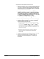
Scanning Applications................................................................................................ 48
Scanning Channels Using the Analog Bus ......................................................... 48
Example: Scanning Using TTL VXIbus Triggers ................................................ 50
Example: Scanning Using BUS Trigger .............................................................. 52
Example: Using the Scan Complete Bit .............................................................. 54
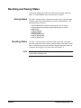
Recalling and Saving States ...................................................................................... 55
Saving States ...................................................................................................... 55
Recalling States .................................................................................................. 55
Detecting Error Conditions ......................................................................................... 56
Using Polling ....................................................................................................... 56
Using Interrupts .................................................................................................. 56
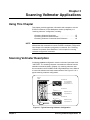
Chapter 3 - Scanning Voltmeter Applications ............................................................ 57
Using This Chapter .................................................................................................... 57
Scanning Voltmeter Description ................................................................................. 57
Measurement Types ........................................................................................... 58
Tree Relays ........................................................................................................ 58
Device Drivers .................................................................................................... 58
The Analog Bus .................................................................................................. 58
Reset Conditions ................................................................................................ 59
Scanning Voltmeter Measurements ........................................................................... 60
Configuring the Scanning Voltmeter ................................................................... 60
Programming the Scanning Voltmeter ................................................................ 61
Scanning Voltmeter Command Quick Reference....................................................... 62
Chapter 4 - Switchbox Command Reference .............................................................. 65
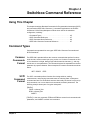
Using This Chapter .................................................................................................... 65
Command Types ........................................................................................................ 65
Common Commands Format ............................................................................. 65
SCPI Command Format ..................................................................................... 65
SCPI Command Reference........................................................................................ 67
ABORt ........................................................................................................................ 68
ARM ........................................................................................................................... 70
ARM:COUNt ....................................................................................................... 70
ARM:COUNt? ..................................................................................................... 70
DISPlay ...................................................................................................................... 72
DISPLay:MONitor:CARD .................................................................................... 72
DISPLay:MONitor:CARD? .................................................................................. 73
DISPLay:MONitor[:STATe] .................................................................................. 73
DISPLay:MONitor[:STATe]? ................................................................................ 74
INITiate....................................................................................................................... 75
INITiate:CONTinuous ......................................................................................... 75
INITiate:CONTinuous? ....................................................................................... 76
INITiate[:IMMediate] ........................................................................................... 76
OUTPut ...................................................................................................................... 77
OUTPut:ECLTrgn[:STATe] .................................................................................. 77
OUTPut:ECLTrgn[:STATe]? ................................................................................ 77
OUTPut[:EXTernal][:STATe] ................................................................................ 78
OUTPut[:EXTernal][:STATe]? .............................................................................. 78
OUTPut:TTLTrgn[:STATe] ................................................................................... 79
OUTPut:TTLTrgn[:STATe]? ................................................................................. 79
4
[ROUTe:] .................................................................................................................. 80
[ROUTe:]CLOSe ................................................................................................. 80
[ROUTe:]CLOSe? ............................................................................................... 81
[ROUTe:]OPEN ................................................................................................... 82
[ROUTe:]OPEN? ................................................................................................. 83
[ROUTe:]SCAN ................................................................................................... 83
[ROUTe:]SCAN:MODE ....................................................................................... 85
[ROUTe:]SCAN:MODE? ..................................................................................... 86
[ROUTe:]SCAN:PORT ........................................................................................ 86
STATus....................................................................................................................... 87
STATus:OPERation:CONDition? ........................................................................ 89
STATus:OPERation:ENABle ............................................................................... 89
STATus:OPERation:ENABle? ............................................................................. 89
STATus:OPERation[:EVENt]? ............................................................................ 90
STATus:PRESet ................................................................................................. 90
SYSTem ..................................................................................................................... 91
SYSTem:CDEScription? ..................................................................................... 91
SYSTem:CPON .................................................................................................. 91
SYSTem:CTYPe? ............................................................................................... 92
SYSTem:ERRor? ................................................................................................ 92
TRIGger ..................................................................................................................... 93
TRIGger[:IMMediate] .......................................................................................... 93
TRIGger:SOURce ............................................................................................... 94
TRIGger:SOURce? ............................................................................................. 95
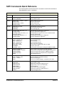
SCPI Commands Quick Reference............................................................................ 96
IEEE 488.2 Common Commands Reference ............................................................ 97
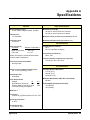
Appendix A - Specifications ......................................................................................... 99
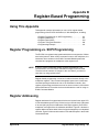
Appendix B - Register-Based Programming ............................................................. 101
Using This Appendix ................................................................................................ 101
Register Programming vs. SCPI Programming........................................................ 101
Register Addressing................................................................................................. 101
The Base Address ............................................................................................ 102
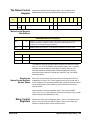
Register Descriptions ............................................................................................... 104
The WRITE Registers ....................................................................................... 104
The READ Registers ........................................................................................ 104
The ID Register ................................................................................................ 104
The Device Type Register ................................................................................ 104
The Status/Control Register ............................................................................. 105
Relay Control Registers .................................................................................... 105
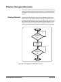
Program Timing and Execution................................................................................ 108
Closing Channels ............................................................................................. 108
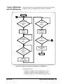
Using a Multimeter with the Multiplexer ............................................................ 109
Programming Example............................................................................................. 110
System Configuration ....................................................................................... 110
Example Program ............................................................................................. 110
5
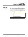
Appendix C - E1476A Error Messages ...................................................................... 115
Error Types .............................................................................................................. 115
Appendix D - Relay Life ............................................................................................. 117
Replacement Strategy.............................................................................................. 117
Relay Life Factors .................................................................................................... 117
End-of-Life Determination ........................................................................................ 117
Index ............................................................................................................................. 119
6
AGILENT TECHNOLOGIES WARRANTY STATEMENT
AGILENT PRODUCT: E1476A 64-Channel, 3-Wire Multiplexer Module
DURATION OF WARRANTY: 3 years
1. Agilent Technologies warrants Agilent hardware, accessories and supplies against defects in materials and workmanship for the period
specified above. If Agilent receives notice of such defects during the warranty period, Agilent will, at its option, either repair or replace
products which prove to be defective. Replacement products may be either new or like-new.
2. Agilent warrants that Agilent software will not fail to execute its programming instructions, for the period specified above, due to
defects in material and workmanship when properly installed and used. If Agilent receives notice of such defects during the warranty
period, Agilent will replace software media which does not execute its programming instructions due to such defects.
3. Agilent does not warrant that the operation of Agilent products will be interrupted or error free. If Agilent is unable, within a reasonable
time, to repair or replace any product to a condition as warranted, customer will be entitled to a refund of the purchase price upon prompt
return of the product.
4. Agilent products may contain remanufactured parts equivalent to new in performance or may have been subject to incidental use.
5. The warranty period begins on the date of delivery or on the date of installation if installed by Agilent. If customer schedules or delays
Agilent installation more than 30 days after delivery, warranty begins on the 31st day from delivery.
6. Warranty does not apply to defects resulting from (a) improper or inadequate maintenance or calibration, (b) software, interfacing, parts
or supplies not supplied by Agilent, (c) unauthorized modification or misuse, (d) operation outside of the published environmental
specifications for the product, or (e) improper site preparation or maintenance.
7. TO THE EXTENT ALLOWED BY LOCAL LAW, THE ABOVE WARRANTIES ARE EXCLUSIVE AND NO OTHER
WARRANTY OR CONDITION, WHETHER WRITTEN OR ORAL, IS EXPRESSED OR IMPLIED AND AGILENT
SPECIFICALLY DISCLAIMS ANY IMPLIED WARRANTY OR CONDITIONS OF MERCHANTABILITY, SATISFACTORY
QUALITY, AND FITNESS FOR A PARTICULAR PURPOSE.
8. Agilent will be liable for damage to tangible property per incident up to the greater of $300,000 or the actual amount paid for the product
that is the subject of the claim, and for damages for bodily injury or death, to the extent that all such damages are determined by a court
of competent jurisdiction to have been directly caused by a defective Agilent product.
9. TO THE EXTENT ALLOWED BY LOCAL LAW, THE REMEDIES IN THIS WARRANTY STATEMENT ARE CUSTOMER’S
SOLE AND EXLUSIVE REMEDIES. EXCEPT AS INDICATED ABOVE, IN NO EVENT WILL AGILENT OR ITS SUPPLIERS BE
LIABLE FOR LOSS OF DATA OR FOR DIRECT, SPECIAL, INCIDENTAL, CONSEQUENTIAL (INCLUDING LOST PROFIT OR
DATA), OR OTHER DAMAGE, WHETHER BASED IN CONTRACT, TORT, OR OTHERWISE.
FOR CONSUMER TRANSACTIONS IN AUSTRALIA AND NEW ZEALAND: THE WARRANTY TERMS CONTAINED IN THIS
STATEMENT, EXCEPT TO THE EXTENT LAWFULLY PERMITTED, DO NOT EXCLUDE, RESTRICT OR MODIFY AND ARE
IN ADDITION TO THE MANDATORY STATUTORY RIGHTS APPLICABLE TO THE SALE OF THIS PRODUCT TO YOU.
U.S. Government Restricted Rights
The Software and Documentation have been developed entirely at private expense. They are delivered and licensed as "commercial
computer software" as defined in DFARS 252.227- 7013 (Oct 1988), DFARS 252.211-7015 (May 1991) or DFARS 252.227-7014 (Jun
1995), as a "commercial item" as defined in FAR 2.101(a), or as "Restricted computer software" as defined in FAR 52.227-19 (Jun
1987)(or any equivalent agency regulation or contract clause), whichever is applicable. You have only those rights provided for such
Software and Documentation by the applicable FAR or DFARS clause or the Agilent standard software agreement for the product
involved.
E1476A 64-Channel, 3-Wire Multiplexer Module User’s Manual
Edition 5
Copyright © 1994, 1996, 2000 Agilent Technologies, Inc. All rights reserved.
7
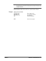
Documentation History
All Editions and Updates of this manual and their creation date are listed below. The first Edition of the manual is Edition 1. The Edition
number increments by 1 whenever the manual is revised. Updates, which are issued between Editions, contain replacement pages to
correct or add additional information to the current Edition of the manual. Whenever a new Edition is created, it will contain all of the
Update information for the previous Edition. Each new Edition or Update also includes a revised copy of this documentation history page.
Edition 1 . . . . . . . . . . . . . . . . . . . . . . . . . . . . . . . . . . . . . . . . . . . . . . .June, 1994
Edition 2 . . . . . . . . . . . . . . . . . . . . . . . . . . . . . . . . . . . . . . . . . . . February, 1996
Edition 3 . . . . . . . . . . . . . . . . . . . . . . . . . . . . . . . . . . . . . . . . . . . . . March, 1996
Edition 4 . . . . . . . . . . . . . . . . . . . . . . . . . . . . . . . . . . . . . . . . . . . . . . . May, 1996
Edition 5 . . . . . . . . . . . . . . . . . . . . . . . . . . . . . . . . . . . . . . . . . . November, 2000
(GLWLRQ5HY6HSWHPEHU
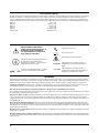
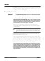
Safety Symbols
Instruction manual symbol affixed to
product. Indicates that the user must refer to
the manual for specific WARNING or
CAUTION information to avoid personal
injury or damage to the product.
Alternating current (AC)
Direct current (DC).
Warning. Risk of electrical shock.
Indicates the field wiring terminal that must
be connected to earth ground before
operating the equipment — protects against
electrical shock in case of fault.
or
Frame or chassis ground terminal—typically
connects to the equipment's metal frame.
Calls attention to a procedure, practice, or
WARNING condition that could cause bodily injury or
death.
Calls attention to a procedure, practice, or
CAUTION condition that could possibly cause damage to
equipment or permanent loss of data.
WARNINGS
The following general safety precautions must be observed during all phases of operation, service, and repair of this product. Failure to
comply with these precautions or with specific warnings elsewhere in this manual violates safety standards of design, manufacture, and
intended use of the product. Agilent Technologies assumes no liability for the customer's failure to comply with these requirements.
Ground the equipment: For Safety Class 1 equipment (equipment having a protective earth terminal), an uninterruptible safety earth
ground must be provided from the mains power source to the product input wiring terminals or supplied power cable.
DO NOT operate the product in an explosive atmosphere or in the presence of flammable gases or fumes.
For continued protection against fire, replace the line fuse(s) only with fuse(s) of the same voltage and current rating and type. DO NOT
use repaired fuses or short-circuited fuse holders.
Keep away from live circuits: Operating personnel must not remove equipment covers or shields. Procedures involving the removal of
covers or shields are for use by service-trained personnel only. Under certain conditions, dangerous voltages may exist even with the
equipment switched off. To avoid dangerous electrical shock, DO NOT perform procedures involving cover or shield removal unless you
are qualified to do so.
DO NOT operate damaged equipment: Whenever it is possible that the safety protection features built into this product have been
impaired, either through physical damage, excessive moisture, or any other reason, REMOVE POWER and do not use the product until
safe operation can be verified by service-trained personnel. If necessary, return the product to Agilent for service and repair to ensure that
safety features are maintained.
DO NOT service or adjust alone: Do not attempt internal service or adjustment unless another person, capable of rendering first aid and
resuscitation, is present.
DO NOT substitute parts or modify equipment: Because of the danger of introducing additional hazards, do not install substitute parts
or perform any unauthorized modification to the product. Return the product to Agilent for service and repair to ensure that safety features
are maintained.
8
Declaration of Conformity
Declarations of Conformity for this product and for other Agilent products may be downloaded from the Internet. There are two methods to obtain
the Declaration of Conformity:
•
Go to http://regulations.corporate.agilent.com/DoC/search.htm . You can then search by product number to find the latest Declaration
of Conformity.
• Alternately, you can go to the product web page (www.agilent.com/find/E1476A), click on the Document Library tab then
scroll down until you find the Declaration of Conformity link.
Notes:
10
Chapter 1
Getting Started
Using This Chapter
This chapter gives guidelines to get started using the E1476A 64-Channel,
3-Wire Multiplexer module (multiplexer), including:
• Multiplexer Description . . . . . . . . . . . . . . . . . . . . . . . . . . . . . . . 11
• Configuring the Multiplexer Module . . . . . . . . . . . . . . . . . . . . .15
• Configuring the Terminal Module . . . . . . . . . . . . . . . . . . . . . . .19
• Configuring the E1586A Rack Mount Terminal Panel. . . . . . . .26
• Programming the Multiplexer . . . . . . . . . . . . . . . . . . . . . . . . . .31
Multiplexer Description
The E1476A 64-Channel, 3-Wire Multiplexer module is a VXIbus C-size
register-based slave device. The multiplexer can operate in a C-size VXIbus
mainframe or a VMEbus mainframe.
The multiplexer “instrument” is the firmware running in the Command
Module (E1406, for example). This firmware is the instrument driver
providing Standard Commands for Programmable Instruments (SCPI)
programming capability. The term “switchbox” is used to refer to an
“instrument” made up of one or more switch modules.
Programming the E1476A can be via a command module using SCPI
commands, through an embedded controller using Compiled SCPI
(C-SCPI), or Standard Instrument Control Language (SICL) or via direct
register access (see Appendix B).
Reed relays are used for each channel and tree relay. Maximum voltage is
120VDC/RMS or 170V peak. Maximum current is 35 mA (non-inductive).
Thermal offset is <4 mV per channel (<2 mV using maximum integration
time with 10 samples averaged).
Chapter 1
Getting Started 11
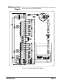
Multiplexer Block
Diagram
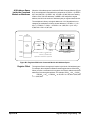
Figure 1-1 shows a simplified block diagram of the E1476A multiplexer with
typical connections to external multimeters.
Figure 1-1. E1476A Simplified Block Diagram
12 Getting Started
Chapter 1
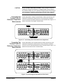
Multiplexer Front
Panel
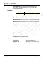
The E1476A multiplexer consists of a switch module and a terminal module.
User inputs are connected to the multiplexer H, L, and G terminal
connections on the terminal module. Figure 1-2 shows the multiplexer
front panel and pin-out descriptions.
(Column #)
(a) (b) (c)
H L G
(Row #)
(32)
Ch 0
Ch 1
Ch 2
Ch 3
Bank A
(1)
Ch 28
Ch 29
Ch 30
Ch 31
4th Row
Description
(a) (b) (c) (d)
H L G
Bank B
(32) Ch 32
Ch 33
Ch 34
Ch 35
Ch 36
Ch 37
Ch 38
Ch 39
Ch 40
Ch 41
Ch 42
Ch 43
Ch 44
Ch 45
Ch 46
Ch 47
Ch 48
Ch 49
Ch 50
Ch 51
Ch 52
Ch 53
H
L
G
H
L
G
Reference Thermistor
Voltage Sense to Channel 93
Analog Bus
(VM Input)
No Connection
H
L
G
Analog Bus
(VM
)
No Connection
(1)
Ch 60
Ch 61
Ch 62
Ch 63
H
L
G
Reference Thermistor
Current Source to Channel 94
Figure 1-2. E1476A Multiplexer Front Panel and Pinouts
Chapter 1
Getting Started 13
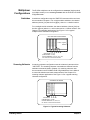
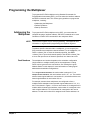
Multiplexer
Configurations
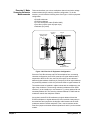
Switchbox
The E1476A multiplexer can be configured as a switchbox (single-module
or multiple-module) or as a scanning voltmeter with the E1411B or E1326B
5-Digit Multimeter.
A switchbox configuration uses the "SWITCH" instrument driver and uses
the commands in Chapter 4. For a single-module switchbox, the channel
address (channel_list) has the form (@nn), where nn = channel number.
For a multiple-module switchbox, the channel address (channel_list) has
the form (@ccnn) where cc = card number and nn = channel number. See
Chapter 2 for switchbox applications. See Figure 1-3 for a typical
multiple-module switchbox configuration.
Switch Laddr=115
Switch Laddr=116
Switch Laddr=114
Switch Laddr=112
Switch Laddr=113
Command Module
MULTIPLE-MODULE SWITCHBOX
Laddr = Logical
Address
Card Number 01 02 03 04 05
(Valid Numbers = 01-99)
Channel Addresses: 1nn, 2nn, 3nn, 4nn,
etc. where nn is the channel number
Figure 1-3. Typical Multiple-Module Switchbox
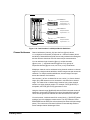
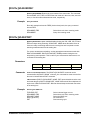
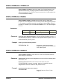
Scanning Voltmeter
A scanning voltmeter configuration uses the voltmeter instrument driver
“VOLTMTR”. The scanning voltmeter commands are different from the
switchbox commands listed in Chapter 4. A scanning voltmeter uses
the commands in the E1326B/E1411B 5-Digit Multimeter User's Manual
to control the switches and make measurements. See Chapter 3 for
scanning voltmeter applications. See Figure 1-4 for a typical scanning
voltmeter configuration.
Switch Laddr=26
Switch Laddr=27
Switch Laddr=25
Command Module
Voltmeter Laddr=24
SCANNING VOLTMETER
Card Number 01 02 03
(Valid Numbers = 01-99)
Channel Addresses: 1nn, 2nn, 3nn,
etc. where nn is the channel number
Figure 1-4. Typical Scanning Voltmeter
14 Getting Started
Chapter 1
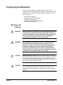
Configuring the Multiplexer
This section gives guidelines to configure the switch module. See
"Configuring the Terminal Modules" for guidelines to configure the terminal
modules and to connect the E1586A Rack Mount Terminal Panel. This
section includes:
• Warnings and Cautions
• Setting the Logical Address Switch
• Setting the Interrupt Priority
• Installing the Multiplexer in a Mainframe
• Connecting the Analog Bus
Warnings and
Cautions
Chapter 1
WARNING
SHOCK HAZARD. Only qualified, service-trained personnel who
are aware of the hazards involved should install, configure, or
remove the multiplexer module. Disconnect all power sources
from the mainframe, the terminal modules, and installed
modules before installing or removing a module.
WARNING
When handling user wiring connected to a terminal module,
consider the highest voltage present accessible on any
terminal. Use only wire with an insulation rating greater than
the highest voltage which will be present on the terminal
module. Do not touch any circuit element connected to the
terminal module if any other connector to the terminal module
is energized to more than 30 VAC rms or 60 VDC.
CAUTION
MAXIMUM VOLTAGE/CURRENT. Maximum allowable voltage per channel,
terminal-to-terminal or terminal-to-chassis for the multiplexer is 120 Vdc or
120 Vac rms (170 Vac peak). Maximum current per channel is 35 mA
(non-inductive). Maximum transient voltage is 1300 V peak. Exceeding any
limit may damage the Multiplexer Module.
CAUTION
WIRING THE TERMINAL MODULE. When wiring to the terminal connectors
on the E1476A terminal module, do not exceed a 5 mm strip back of
insulation to prevent the possibility of shorting to other wiring on adjacent
terminals.
Getting Started 15
CAUTION
Setting the Logical
Address Switch
STATIC ELECTRICITY. Static electricity is a major cause of component
failure. To prevent damage to the electrical components in the multiplexer,
observe anti-static techniques whenever removing, configuring, and
installing a module. The multiplexer is susceptible to static discharges.
Do not install the multiplexer module without its metal shield attached.
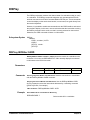
The logical address for the E1476A multiplexer is set with the Logical
Address Switch on the module. The logical address switch factory setting
for the E1476A is 112. Valid addresses are from 1 to 254 for static
configuration (the address you set on the switch) and address 255 for
dynamic configuration.
The E1476A supports dynamic configuration of the address. This means
the address is set programmatically by the resource manager when it
encounters a module with address 255 that supports dynamic configuration.
See Figure 1-5 for switch position information.
NOTE
When using the E1406 Command Module, the address switch value must
be a multiple of 8 if the module is the first module in a switchbox used with
a VXIbus command module using SCPI commands. When in the scanning
voltmeter configuration, the address switch value must be sequential to the
voltmeter address.
Logical
Address
Switch
Location
Logical Address = 112
128
64
32
16
8
4
2
1
Decimal Value
1=CLOSED
0=OPEN
64+32+16=112
OPEN = Switch Set To 0 (OFF)
CLOSED = Switch Set To 1 (ON)
Figure 1-5. Setting the Logical Address Switch
16 Getting Started
Chapter 1
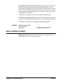
Setting the Interrupt
Priority
For most applications, the interrupt priority level should not need to be
changed. Interrupts are enabled at power-up, after a SYSRESET or after
resetting the module via the Control Register. An interrupt is generated after
any relay Control Register is accessed when interrupts are enabled. The
interrupt is generated approximately 1.3ms after one of the registers is
accessed.
The Interrupt Request Level switch selects the priority level to be asserted.
The Interrupt Request Level switch is set in position 1 when shipped from
the factory. The interrupts are disabled when set to level 0. Be careful when
deciding to disable the interrupts, as both the "VOLTMTR" and "SWITCH"
drivers require that interrupts be enabled.
To change the setting, rotate the switch so the arrow points to the interrupt
priority level desired. Interrupts can also be disabled using the E1476A
Status/Control Register. See Figure 1-6 for the Interrupt Request Level
switch.
NOTE
Some mainframes may require that backplane jumpers be set correctly for
each slot used. See the appropriate mainframe manual for details.
Interrupt Request
Level Rotary
Switch Location
Interrupt Request (IRQ)
Level 0 = Interrupt Disabled
Figure 1-6. Setting Interrupt Request (IRQ) Priority
Chapter 1
Getting Started 17
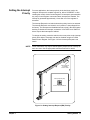
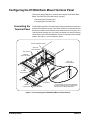
Installing the
Multiplexer in a
Mainframe
1
The E1476A can be installed in any slot (except slot 0) in a C-Size VXIbus
mainframe. See Figure 1-7 for steps to install the multiplexer in a mainframe.
Set the extraction levers out.
2
Slide the E1476A into any slot
(except slot 0) until the backplane
connectors touch.
Extraction
Levers
3
4
Seat the E1476A into
the mainframe by pushing
in the extraction levers.
Tighten the top and bottom screws
to secure the multiplexer to the
mainframe.
NOTE: The extraction levers will not
seat the backplane connectors on older
VXIbus mainframes. You must manually
seat the connectors by pushing in the
module until the module's front panel is
flush with the front of the mainframe. The
extraction levers may be used to guide or
remove the multiplexer.
To remove the multiplexer from the mainframe,
reverse the procedure.
Figure 1-7. Installing the Multiplexer Module in a VXIbus Mainframe
18 Getting Started
Chapter 1
Configuring the Terminal Module
This section gives guidelines to configure the terminal module, including:
• Terminal Module Descriptions
• Wiring Terminal Modules
• Attaching a Terminal Module to the Multiplexer
• Connecting the Analog Bus
Terminal Module
Descriptions
The E1476A 64-Channel, 3-Wire Multiplexer module consists of a
multiplexer switch card and a spring clamp type terminal module. The
screwless terminals use a spring clamp terminal for connecting solid or
stranded wire. Connection is made with a push of a three-pronged insertion
tool (part number 8710-2127) that is shipped with the multiplexer.
If the spring clamp type terminal module is not desired, a crimp-and-insert
terminal module (Option A3E) and an interface to rack mount terminal panel
(Option A3F) are available. See "Configuring the E1586A Rack Mount
Terminal Panel" for details on using Option A3F.
Standard Terminal
Module
Figure 1-8 shows the E1476A spring clamp standard terminal module
connectors and associated channel numbers. See "Multiplexer Front Panel"
for the connector pin-outs that mate to to terminal module.
Bank B
Terminals
Bank A
Terminals
Analog Bus to VM
(Input)
Analog Bus to VM
( )
Figure 1-8. E1476A Standard Terminal Module
Chapter 1
Getting Started 19
Terminal Module Option
A3E
Terminal module Option A3E (see Figure 1-9) provides a crimp-and-insert
terminal module that allows you to crimp connectors onto wires which are
then inserted directly into the multiplexer’s mating connector. See the
pin-out diagram (Figure 1-2) to make the connections. Table 1-1 shows the
accessories that can be used with crimp-and-insert Option A3E.
Figure 1-9. Option A3E Crimp-and-Insert Connector
Table 1-1. Option A3E Terminal Module Accessories
Accessory
Description
Specifications
Crimp-andInsert Contacts
These contacts may be crimped onto a
conductor and then inserted into a
crimp-and-insert connector. The crimp
tool kit is required to crimp the contacts
onto a conductor and remove the
contact from the connector.
Order Agilent part number 1252-6533 or
ERNI part number 014728.
Wire Gauge Range: 20-26 AWG
Quantity: 250 each
Plating: Gold Plated Contact
Maximum Current: 2A at 70oC
Crimp-andInsert Tools
The hand crimp tool (Agilent part number 8710-2306 or ERNI part number 014374) is used for crimping
contacts onto a conductor. The pin extractor tool (Agilent part number 8710-2307 or ERNI part number
471555) is required for removing contacts from the crimp-and-insert connector. These products are not
included with Option A3E or with the terminal option accessories listed earlier.
Extra Crimpand-Insert
Connectors
The crimp-and-insert connector is normally supplied with Option A3E. Contact Agilent if additional
connectors are needed.
96-Pin Connector Body: Agilent Part Number 1252-6532; ERNI Part Number 024069
160-Pin Connector Body: Agilent Part Number 1252-6531; ERNI Part Number 024070
20 Getting Started
Chapter 1
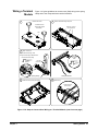
Wiring a Terminal
Module
1
Figure 1-10 gives guidelines to connect user (field) wiring to the spring
clamp and to the crimp-and-insert terminal modules.
Remove clear cover
2
Remove and retain wiring exit panel
A. Release screws.
Remove 1 of the 3
wire exit panels.
B. Press tab forward
and release.
Tab
3
Make connections
Depress terminal lever(s). Insert
wire(s) into terminal(s). Release levers.
Use wire
size 22-26
AWG
Use wire size 22-26 Gage
5mm
0.2"
Part No.
8710-2127
2.5mm
0.1"
Spring Clamp
4
Install connectors (Crimp-and-Insert)
Crimp-and-Insert
5
Route wiring
Tighten wraps to
secure wires.
Figure 1-10. Steps to Connect User Wiring to a Terminal Module (cont’d on next page)
Chapter 1
Getting Started 21
6
7
Replace wiring exit panel
Replace clear cover
A. Hook in the top cover tabs
onto the fixture.
B. Press down and
tighten screws.
Cut required
holes in panels
for wire exit.
8
Keep wiring exit panel
hole as small as
possible.
9
Install the terminal
module
Push in the extraction levers to lock the
terminal module onto the E1476A
Extraction
Levers
E1476A
Module
Figure 1-10. Steps to Connect User Wiring to a Terminal Module (cont’d)
22 Getting Started
Chapter 1
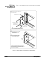
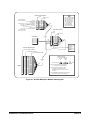
Attaching a
Terminal Module to
the Multiplexer
1
Figure 1-11 gives guidelines to attach a terminal module to the multiplexer.
Extend the extraction levers on the
terminal module.
Extraction Lever
Use small screwdriver
to release the two
extraction levers
E1476A
Module
Extraction Lever
2
3
Align the terminal module connectors
to the E1476A module connectors.
Apply gentle pressure to attach
the terminal module to the
E1476A module.
Push in the extraction levers
to lock the terminal module
onto the E1476A module.
Extraction
Levers
To remove the terminal module from the E1476A,
use a small screwdriver to release the two extraction
levers and push both levers out simultaneously
to free it from the multiplexer.
Figure 1-11. Steps to Attach a Terminal Module to the Multiplexer
Chapter 1
Getting Started 23
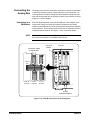
Connecting the
Analog Bus
The analog bus provides a common bus to all switch modules in a switchbox
or scanning voltmeter to which a single voltmeter can be connected. You
must connect the flat ribbon analog bus cables between multiplexers and
other VXI modules that have an analog bus (both C-size modules or B-size
modules in a C-size adapter).
Connecting to a
Multimeter
E1411B 5-Digit Multimeter users (and E1326B in a C-size adapter) must
continue the analog bus connection between multiplexers and switch
modules to the multimeter to use the scanning and measurement capability
of the multimeter. These cables provide the input to the multimeter from the
multiplexer/switch channels. See Figure 1-12 for connection details.
NOTE
Use the 19.5 inch analog bus cable (part number E1326-61611) for analog
bus connection between an E1326B and the E1476A.
Analog Bus Cables
(E1400-61605)
Command
Module
E1411B
ANALOG
BUS
E1411B
Multimeter
E1476A
Multiplexer
E1476A
Multiplexer
E1476A
Multiplexer Modules
Figure 1-12. E1411B Connections to the Analog Bus
24 Getting Started
Chapter 1
Connecting to an
External Measurement
Device
An external measurement device can be connected to the analog bus
by using the terminal module's “VM Input” and “VM WI” terminals.
See Figure 1-13 for connection information.
Bank A
Terminals
Bank B
Terminals
Analog Bus to VM
(Input)
VM
Input
(H-L-G)
Analog Bus to VM
VM
(H-L-G)
To External Measuring Device
Figure 1-13. Externally Connecting to the Analog Bus
Chapter 1
Getting Started 25
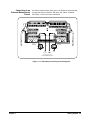
Configuring the E1586A Rack Mount Terminal Panel
This section gives guidelines to connect and configure the E1586A Rack
Mount Terminal Panel (Terminal Panel), including:
• Connecting the Terminal Panel
• Configuring the Terminal Panel
Connecting the
Terminal Panel
The E1586A Rack Mount Terminal Panel provides extended connections to
the E1476A multiplexer module. The Terminal Panel is recommended if the
E1476A is located some distance from the measurement connections. The
Terminal Panel provides up to 32 (3-wire) connections to allow 32 channel
connections to the E1476A multiplexer module via the Option A3F terminal
module. See Figure 1-14 for connection details.
E1476A Multiplexer Module
Option A3F
Terminal Module
SCSI Cables
*
Optional
Option 001 Board
Option A3F
Terminal Module
E1586A
Terminal Panel
SCSI Cables
E1586A
Terminal Panel
*
Optional
Option 001 Board
To use the E1486 Terminal Panel WITHOUT
the Option 001 Board, Plug the SCSI Cables
directly into the E1586 Terminal Panel
Figure 1-14. Connecting the E1586A Rack Mount Terminal Panel
26 Getting Started
Chapter 1
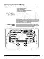
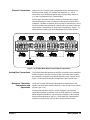
Option A3F Terminal
Module
As shown in Figure 1-14, E1476A Terminal Module Option A3F allows an
E1476A multiplexer module to be connected to an E1586A Rack Mount
Terminal Panel. This option provides four SCSI plugs on a terminal module
to enable connection to a rack-mount terminal panel using four terminal
modules. See Figure 1-15 for the front panel view and connector pinouts of
the Option A3F Terminal Module.
E1476A
OPTION A3F
Chan
0-15
Chan
16-31
Chan
32-47
Chan
48-63
Figure 1-15. Terminal Module Option A3F Pinouts
Chapter 1
Getting Started 27
Terminal Panel Cables
There are two different SCSI cables available for connecting the E1586A
Rack Mount Terminal Panel to the E1476A Option A3F Terminal Module.
In both cases, four cables are required if all 64 channels are needed. This
also requires two E1586A Rack Mount Terminal Panels since a single
terminal panel only connects 32 channels. The cables do not come with the
E1476A Option A3F and must be ordered separately. The cables are:
• Standard Cable. This cable (E1588A) is a 16-channel twisted pair
cable with an outer shield and is suitable for relatively short cable
runs.
• Custom Length Cable. This cable (Z2220A Option 050) is available
in custom lengths. It is a 16-channel twisted pair cable with each
twisted pair individually shielded to provide better quality shielding
for longer cable runs.
HF Common Mode
Filters
Optional high frequency common mode filters are available for the E1586A
Rack Mount Terminal Panel input channels. These filters filter AC common
mode signals in the cable that connects the terminal panel and the device
under test. These filters are useful for filtering small common mode signals
below 5Vp-p. To order these filters, order E1586A Option 001.
Connecting the Terminal
Panel
The E1586A Terminal Panel can be mounted in a standard size instrument
rack. To minimize temperature gradients across the panel, the panel should
be mounted in the rack such that it is away from the other heat sources. The
bottom of the rack is usually the preferred location.
Take particular care to minimize the temperature differences across the
horizontal width of the Terminal Panel, since it is most susceptible to
horizontal temperature gradients across its longest dimension. See Figure
1-13 for guidelines to connect the E1586A Terminal Panel to the E1476A
Option A3F terminal modules.
Configuring the
Terminal Panel
The E1586A Rack Mount Terminal Panel (Terminal Panel) provides
extended connections to the E1476A multiplexer module. Since the
Terminal Panel is used in place of the standard E1476A terminal module,
all operations in Chapter 2 (except temperature measurements) apply to the
Terminal Panel. However, since the Terminal Panel has three thermistors to
make reference temperature measurements, reference temperature
measurements are different than for the standard E1476A terminal module.
All channel and Analog Bus connections to make measurements have
corresponding connections on the Terminal Panel. The following sections
describe channel and analog bus connections to the Terminal Panel and
connections for reference temperature measurements.
28 Getting Started
Chapter 1
Channel Connections
Channels on the Terminal Panel correspond directly to channels on the
E1476A terminal module. For example, the channel 2 H, L, and G
connections on the E1476A multiplexer have corresponding channel 2
H, L, and G connections on the Terminal Panel.
Since a single Terminal Panel has a total of 32 channels, two Terminal
Panels are required to make connections to all channels of the E1476A
multiplexer. The Bank A channels (00-31) connect to channels 0-31 on the
first Terminal Panel and the Bank B channels (32-63) connect to channels
32-63 (shown in parentheses) of the second Terminal Panel. Figure 1-16
shows channel numbering for the E1586A Rack Mount Terminal Panel.
Figure 1-16. E1586A Rack Mount Terminal Panel Connections
Analog Bus Connections
The Terminal Panel also provides Analog Bus connections to the multiplexer
module. However, since the terminal module is used with other modules,
the Analog Bus connections are labeled differently on the Terminal Panel.
Figure 1-16 shows the Analog Bus connections to the Terminal Panel.
Reference Thermistor
Connections and
Operations
The E1586 Terminal Panel’s three thermistors are located next to the
channel 3 terminal block, between channels 11 and 16 and next to channel
24 (see Figure 1-16).
The thermistor excitation source is usually supplied by an externally
connected multimeter or voltmeter, such as the E1326/E1411 multimeter.
When using an E1326/E1411, the excitation is available on the Terminal
Panel terminals labeled HI-I and LO-I. The E1326/E1411 generates this
excitation using the 2-wire or 4-wire Ohms measurement functions.
Chapter 1
Getting Started 29
CAUTION
DO NOT EXCEED COMPLIANCE VOLTAGE. If using a single E1326/E1411
multimeter to supply the excitation for multiple E1586A Terminal Panels,
the resultant voltage sum of the voltages developed across the thermistors
could exceed the compliance voltage of the multimeter. This is especially
true if attempting to excite all three thermistors on the Terminal Panels.
Connecting One
Terminal Panel for
Reference Temperature
Measurements
In this configuration, a single Terminal Panel is used to provide up to 32
channels for temperature measurements. This provides the excitation
current to all three on-board thermistors on the Terminal Panel. Figure 1-17
shows connections for a single Terminal Panel.
Figure 1-17. Connecting Three Thermistors on a Single Panel
Connecting Two
Terminal Panels for
Reference Temperature
Measurements
In this configuration, two Terminal Panels are used to provide up to 64
channels for temperature measurements. This provides the excitation
current to all six on-board thermistors on the Terminal Panels. Figure 1-18
shows the connection for two Terminal Panels.
Figure 1-18. Connecting Six Thermistors on Two Panels
30 Getting Started
Chapter 1
Programming the Multiplexer
To program the E1476A multiplexer using Standard Commands for
Programmable Instruments (SCPI), you must select the interface address
and SCPI commands used. This section gives guidelines to program the
multiplexer, including:
• Addressing the Multiplexer
• Default Conditions
• Start-Up Exercises
Addressing the
Multiplexer
To program the E1476A multiplexer using SCPI, you must select the
computer language, interface address, and SCPI commands to be used.
Guidelines to select SCPI commands for the multiplexer follow.
NOTE This discussion applies only to SCPI programming. See Appendix B for
information on register-based programming of multiplexer registers.
To address specific channels within a multiplexer, you must specify the
SCPI command and multiplexer channel address. For the multiplexer, use
CLOSe <channel_list> to close the channels specified. Use OPEN
<channel_list> to open the channels specified. Use SCAN <channel_list>
to close and open the set of channels specified, one channel at a time.
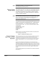
Card Numbers
The multiplexer card number depends on the switchbox configuration
(single-module or multiple-module) set for the multiplexers. Leading
zeroes can be ignored for the card number. See "Setting the Logical
Address Switch" in this chapter for more information on setting logical
addresses and switchbox configurations.
For a single-module switchbox, the card number is always 01. For a
multiple-module switchbox, the card numbers are 01, 02,...,nn. The module
with the lowest logical address is card number 01, the module with the next
lowest logical address is card number 02, etc.
For example, assume three multiplexers are configured to form a
multiple-module switchbox instrument with logical addresses of 112, 113,
and 114 as shown in Figure 1-19. Since card number 01 is assigned to the
module with the lowest logical address, card number 01 is assigned to the
card at logical address 112. Card number 02 is assigned to the card at
address 113 and card number 03 is assigned to the card at address 114.
Chapter 1
Getting Started 31
128
64
32
16
8
4
2
1
Module
CARD NUMBER 01
Multiplexer Number 1
Logical Address = 112
Secondary Address = 14
128
64
32
16
8
4
2
1
CARD NUMBER 02
Multiplexer Number 2
Logical Address = 113
128
64
32
16
8
4
2
1
CARD NUMBER 03
Multiplexer Number 3
Logical Address = 114
Figure 1-19. Card Numbers in a Multiple-Module Switchbox
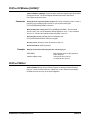
Channel Addresses
Channel addresses (channel_list) have the form (@ccnn) where
cc = multiplexer card number (01-99) and nn = channel numbers (00-63
and 90-94). Channels 90 through 94 are tree relays related to the analog bus
and the reference thermistor used for thermocouple measurements.
You can address single channels (@ccnn), multiple channels
(@ccnn,ccnn,...), sequential channels (@ccnn:ccnn), groups of
sequential channels (@ccnn:ccnn,ccnn:ccnn) or any combination.
Multiplexer channels can be addressed using channel numbers or channel
ranges. For a single-module switchbox, channel ranges can span across the
channels. For multiple-module switchboxes, channel ranges can span
across the channels of all modules.
Use commas (,) to form a channel list or use a colon (:) to form a channel
range. Only valid channels can be accessed in a channel list or channel
range. The channel list or channel range must be from a lower channel
number to a higher channel number. For example, CLOS (@100:215) is
acceptable, but CLOS (@215:100) generates an error.
Using the channel range (@n00:n99) with the SCAN command causes all
channels to be scanned except the tree relays (channels 90 through 94).
These are not typical scan channels and are not included in a scan list.
You can however, include channel 93 in a scan list (e.g., (@100:193)) when
making a four-wire resistance measurement. The only restriction is that
SCAN:MODE must be FRES (four-wire resistance) for channel 93 (the voltage
sense). The current source channel is 94 and is automatically switched.
Some example channel lists/ranges follow.
32 Getting Started
Chapter 1
Channel Lists:
CLOS(@100,112)
OPEN(@203,210)
! Close channels 00 and 12 on card 01
! Open channels 03 and 10 on card 02
Channel Ranges:
OPEN(@100:163)
SCAN(@100:163)
SCAN(@100:199)
SCAN(@100:223)
! Open all channels on card 01
! Scan all channels on card 01
! Scan all channels on card 01
! Scan all channels on card 01 and
! channels 00 through 23 on card 02
! Scan channels 0 through 4 on card 1,
! scan channels 0 through 4 on card 2,
! and scan channel 0 on card 3
SCAN(@100:104,200:204,300)
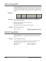
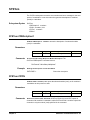
Default Conditions
If you want to use the E1476A as a switchbox or scanning voltmeter
instrument using SCPI commands, you must first install the appropriate
device driver into the E1406 Command Module. For switchbox applications,
install “SWITCH” driver Rev A.08.00 or later. For scanning voltmeter
applications, install “VOLTMTR” driver Rev A.06.00 or later. See "Start-Up
Exercises" for procedures to install device drivers.
At power-on or following a reset of the module (*RST command), all
channels are open. A *RST command invalidates the current scan list and
you must specify a new scan list. Command parameters are set to the
default conditions in Table 1-2.
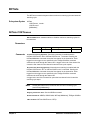
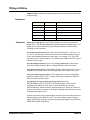
Table 1-2. E1476A Default Conditions
Parameter
Default
Description
ARM:COUNt
1
Number of scanning cycles is one.
TRIGger:SOURce
IMM
Advances through a scanning list
automatically.
INITiate:CONTinuous
OFF
Number of scanning cycles is set by
ARM:COUNt
OUTPut[:STATe]
OFF
Trigger output from EXT, TTL, or
ECL sources is disabled.
[ROUTe:]SCAN:MODE
NONE
Channel list is set up for volts
measurement.
[ROUTe:]SCAN:PORT
NONE
Analog bus connections are
disabled from channels.
Execute SCAN:PORT ABUS to enable use of the analog bus for the SCAN
command. A CLOSe command requires that you also close the appropriate
tree relay to make connection to the analog bus.
Chapter 1
Getting Started 33
Start-Up Exercises
This section provides five start-up exercises you can use to get the E1476A
64-Channel, 3-Wire Multiplexer module operational, including:
• Exercise 1: Check Device Driver (E1406 only)
• Exercise 2: Query Module Identity
• Exercise 3: Perform Open, Close, and Scan Operations
• Exercise 4: Check for System Errors
• Exercise 5: Make Scanning Voltmeter Measurements
NOTE We recommend you do not make user connections to the multiplexer until
you have verified correct multiplexer operation. If you have already
connected user inputs to the terminal module, you may want to remove
the terminal module from the switch module while doing these exercises.
Exercise 1: Check Device
Driver (E1406 Only)
If you use an E1406 Command Module, you can check the command
module for the correct version of the "SWITCH" device driver for the
E1476A. Skip this step and go to Exercise 2 if you do not use an
E1406 Command Module.
Power-up the mainframe with the command module installed. The
command module is the resource manager at logical address 0 and is
typically addressed in the mainframe by 70900. Input this BASIC program
into your computer.
10
20
30
40
50
DIM A$[256]
OUTPUT 70900;"DIAG:DRIV:LIST?"
ENTER 70900;A$
PRINT A$
END
RUN the program and look for the device driver
"SWITCH,SWITCHBOX,A.08.00,RAM". RAM could be FLASH (flash ROM)
depending on where the device driver is loaded. DIAGnostic:DRIVer:LIST?
queries the command module at address 70900 for a list of the device
drivers loaded in the command module. A typical response should be similar
to the following and will depend on the specific drivers that were previously
loaded in the command module.
SYSTEM,E1406A,A.08.00,ROM;A.04.02,ROM;VOLTMTR,E1326A,
A.06.00,ROM;SWITCH,SWITCHBOX,A.08.00,RAM;COUNTER,
E1332A,A.04.02,ROM;E1333A,A.04.02,ROM;DIG_I/O,E1330A,
A.04.03,ROM;D/A,E1328A,A.04.02,ROM
If you are using an E1411B or E1326B multimeter with E1476A
multiplexer(s) configured as a scanning voltmeter, you will need the
"VOLTMTR" device driver version A.06.00 (or later). For all non-scanning
voltmeter applications, you will need the "SWITCH" driver version A.08.00
(or later). To load a new SWITCH or VOLTMTR device driver, use the VXI
Installation Consultant (VIC) on the Agilent Technologies Universal
Instrument Drivers CD.
34 Getting Started
Chapter 1
NOTE For the latest information on instrument drivers, see
http://www.agilent.com/find/inst_drivers.
Exercise 2: Query
Module Identity
Turn mainframe power OFF. If you want to set a logical address other than
the factory-set address of 112, see "Setting the Logical Address Switch" to
set a different logical address for the multiplexer. Install the multiplexer
module in the mainframe. See "Installing the Multiplexer in a Mainframe"
for steps to install the multiplexer.
NOTE If you have already connected user inputs to the terminal module, you may
want to disconnect the terminal module from the switch module for this
exercise. See "Attaching a Terminal Module to the Multiplexer" to
disconnect the terminal module.
Turn mainframe power ON and enter the following BASIC program into your
computer. For this program, the GPIB Select Code = 7, primary address =
09, and logical address = 112. The logical address divided by 8 = the
secondary address (112/8 = 14). Thus, the instrument address is 70914.
10
20
30
40
50
DIM A$[256]
OUTPUT 70914;"*IDN?"
ENTER 70914;A$
PRINT A$
END
RUN the program. The response should be as follows. The device driver
revision must be A.08.00 or later.
"HEWLETT PACKARD,SWITCHBOX,0,A.08.00"
Exercise 3: Perform
Open, Close, and Scan
Operations
This exercise performs close, open and scanning operations and queries
the status byte. Now that communication with the module has been
established, you can perform some close, open and scan operations and
use the "SCAN COMPLETE" bit in the Status Operation Event register
(bit 8).
Operation Event Register bit 8 designates scan complete when high.
Reading this register clears the register (all bits to zero). This bit is monitored
by serial polling (SPOLL) the status byte register (bit 7) in line 70. You may
want to look at the STATUS command in Chapter 4 which graphically shows
the relationship of these two bits and all status registers relating to this
module.
Input this BASIC program into your computer. Do not input the comments
preceeded by " ! ".
Chapter 1
Getting Started 35
10
20
30
40
50
60
70
80
90
100
110
120
130
DIM A$[256]
OUTPUT 70914;"CLOSE (@100, 101, 102:163)"
OUTPUT 70914;"*RST"
OUTPUT 70914;"STAT:OPER:ENAB 256"
OUTPUT 70914;"SCAN (@100:163)"
OUTPUT 70914;"INIT"
WHILE NOT BIT (SPOLL(70914),7)
PRINT "WAITING FOR SCAN COMPLETE"
END WHILE
OUTPUT 70914;"STAT:OPER?"
ENTER 70914;A$
PRINT "STAT:OPER:EVENT BIT 8 = ",A$
END
!Dimension array to hold data entered
!Close all channels
!Open all channels by resetting module
!Enable bit 8 of status operation event register
!Scan all channels
!Initiate the scan using the default TRIG[:IMM]
!Serial poll bit 7 of the status byte until it is high
!Query the status operation event register
!Bit 8 reported high (status byte bit 7 was high)
!Print response to the STAT:OPER query
RUN the program. You should hear channel relays opening and closing,
especially when a large channel list is scanned.
Exercise 4: Check for
System Errors
You can add the following lines to the program in Exercise 3 to verify that
no system errors were generated. It is always a good idea to check if your
program causes the instrument to report any errors during program
development (such as command strings that are invalid and cause an error
to be sent to the instrument's error queue). You can read the instrument's
error queue by inserting the following four program lines (all errors are read
until the error queue is "+0, No errors").
121 REPEAT
122
OUTPUT 70914;"SYST:ERR?"
123
ENTER 70914; A,A$
A$ gets the
!A gets the error number,
!error message
124
PRINT A,A$
125 UNTIL A=0
See "Using Interrupts With Error Checking" in Chapter 2 for detecting errors
with interrupts. For example, inserting the following (incorrect) program line:
51 OUTPUT 70914;"TRIG:SOURC BUS"
will cause an error to be sent to the error queue because TRIG:SOURC BUS
is an incorrect command header (must be TRIG:SOUR BUS). The instrument
still functions using the default value TRIG:IMMediate. To know that an error
was reported and your instrument is doing what you intended it to do, you
must read the error register with a SYSTem:ERRor? command.
You can insert this program segment at different places in your program to
see where the error is generated when debugging your program if it cannot
be determined from the error message or by examining the program lines.
In this case, the error is returned as -113, "Undefined header" which means
the command header was incorrectly specified. This error is generated by
the instrument driver while trying to parse the command (the error -113 is
documented in the command module manual).
36 Getting Started
Chapter 1
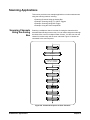
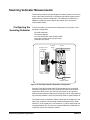
Exercise 5: Make
Scanning Voltmeter
Measurements
This exercise allows you to close multiplexer channels and make voltage
measurements using a scanning voltmeter configuration. To do this
exercise, you will need the following items. See Figure 1-20 for equipment
configuration.
• E1411B multimeter
• E1476A multiplexer
• 2.5 inch Analog Bus cable (E1400-61605)
• Zero Ohm jumpers (such as paper clips)
• Resistors (any value)
Analog Bus Cable
(E1400-61605)
Command
Module
E1411B
ANALOG
BUS
E1411B
Multimeter
E1476A
Multiplexer
E1476A
Multiplexer Module
Figure 1-20. Exercise 5: Equipment Configuration
Since the E1411B multimeter and E1476A multiplexer form a scanning
voltmeter configuration, the E1476A must have a logical address that is
sequential to the E1411B. Also, the E1411B must be at an instrument
address (logical address divisible by 8). Set the E1411B to logical address
24 (secondary address is 24/8 = 03) and the E1476A to logical address 25.
The modules must be installed in adjacent slots with the multiplexer to the
right of the multimeter. The scanning voltmeter is addressed from GPIB
interface 7 (or the interface you use instead of 7), primary address 09 and
secondary address 03. The scanning voltmeter address is 70903 and the
multimeter controls the multiplexer module.
As required, set the E1411B multimeter to logical address 24 and the
E1476A multiplexer to logical address 25. Next, install the instruments in
the mainframe and connect the Analog Bus cable between the E1411B
multimeter and the E1476A multiplexer. Then, connect resistors and/or
Zero Ohm jumpers to desired channels (between 0 and 31) on the terminal
module.
Chapter 1
Getting Started 37
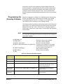
When the configuration is complete, turn mainframe power ON and verify
that the "VOLTMETR" driver version A.06.00 is installed in the E1406
Command Module (see Exercise 1). If the appropriate "VOLTMETR" driver
is installed, run the following program.
This program scans channels 0 through 31 of the multiplexer and makes a
voltage measurement on each channel. The measured readings are entered
into the computer and displayed after the scan. You can then check the
measured readings with the values of the resistor(s) you installed on the
channels.
10
20
30
40
DIM Rdgs(1:32)
CLEAR 70903
OUTPUT 70903;"*RST"
OUTPUT 70903;"MEAS:VOLT:DC?(@100:131)"
50 ENTER 70903;Rdgs(*)
60 PRINT Rdgs(*)
70 END
38 Getting Started
! Dimension array to store readings
! Clear the scanning voltmeter
! Reset the scanning voltmeter
! Configure the multimeter for DC voltage
! measurements and specify channel list
! to scan (channels 00 through 31)
! Enter measured readings
! Display measured readings
Chapter 1
Chapter 2
Switchbox Applications
Using This Chapter
This chapter gives application information to use the E1476A multiplexer
in the “switchbox” configuration, including:
• Switchbox Definition . . . . . . . . . . . . . . . . . . . . . . . . . . . . . . . . .39
• Switching Applications . . . . . . . . . . . . . . . . . . . . . . . . . . . . . . .41
• Scanning Applications . . . . . . . . . . . . . . . . . . . . . . . . . . . . . . .48
• Recalling and Saving States . . . . . . . . . . . . . . . . . . . . . . . . . . .55
• Detecting Error Conditions . . . . . . . . . . . . . . . . . . . . . . . . . . . .56
Switchbox Definition
A “switchbox” can be a single multiplexer module or multiple multiplexer
modules. It can also include other switch modules that are controlled by the
same “switchbox” device driver. See Figure 2-1 for a typical multiple-module
switchbox.
NOTE
A switchbox configuration does not include a multimeter (such as the
E1411B) installed in the mainframe, and measurements must be made
using an external multimeter. In contrast, a "scanning voltmeter"
configuration does include a multimeter installed in the mainframe. See
Chapter 3 for scanning voltmeter applications.
128
64
32
16
8
4
2
1
Command
Module
CARD NUMBER 01
Multiplexer Number 1
Logical Address = 112
Secondary Address = 14
128
64
32
16
8
4
2
1
CARD NUMBER 02
Multiplexer Number 2
Logical Address = 113
128
64
32
16
8
4
2
1
CARD NUMBER 03
Multiplexer Number 3
Logical Address = 114
Figure 2-1. Typical Switchbox Configuration
Chapter 2
Switchbox Applications 39
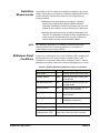
Switchbox
Measurements
The multiplexer can be configured in switchbox configuration to perform
voltage, 2-wire ohms, 4-wire ohms or temperature measurements via the
internal analog bus. Measurements can be made using switching or
scanning methods.
• Switching. All measurements can be made by individually
switching the channels with CLOSe and OPEN commands.
Individually switching the channels requires that you also close
appropriate tree relay(s) to connect channels to the analog bus.
• Scanning. All measurements can be made by scanning a list of
channels. The advantage of scanning is that the appropriate tree
relays are closed automatically when you scan a channel list
with the SCAN command and set SCAN:PORT ABUS.
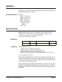
NOTE
Multiplexer Reset
Conditions
See "Switching Applications" for examples of measurements using
switching methods. See "Scanning Applications" for examples of
measurements using scanning methods.
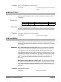
At power-on or following the reset of the multiplexer (*RST command), all
64 channels and the tree relays are open. In addition, after a *RST
command, the current scan channel list is invalidated. Table 2-1 lists the
parameters and default values for the functions following turn-on or reset.
Table 2-1. E1476A Default Conditions for Power-on and Reset
Parameter
40 Switchbox Applications
Default
Description
ARM:COUNt
1
Number of scanning cycles is one.
TRIGger:SOURce
IMM
Advances through a scanning list
automatically.
INITiate:CONTinuous
OFF
Number of scanning cycles is set
by ARM:COUNt
OUTPut[:STATe]
OFF
Trigger output from EXT, TTL, or
ECL sources is disabled.
[ROUTe:]SCAN:MODE
NONE
Channel list is set for volts
measurement.
[ROUTe:]SCAN:PORT
NONE
Analog bus connections are
disabled from channels.
Channel state
All 64 channels are open (channels 00 - 63)
Tree relay state
All tree relays are open (channels 90 - 94)
Channel list from SCAN
command (after *RST)
Current channel list is invalidated following a
reset of the module with *RST command.
Chapter 2
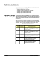
Switching Applications
This section provides some example applications to make measurements
using the switching method, including:
• Switching Channels to the Analog Bus
• Example: Connecting a Channel to the Analog Bus
• Example: 2-Wire Resistance Measurements
• Example: 4-Wire Resistance Measurements
• Example: Temperature Measurements
Switching Channels
to the Analog Bus
For the switching method, when OPEN and CLOSe are use to individually
switch channels, the appropriate tree relay (VSA, VSB or CS) must also be
closed to connect channels to the analog bus to make measurements from
the analog bus.
Once closed, a tree relay remains closed until specifically opened (OPEN
command, remove power from the module or reset the module with a *RST
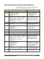
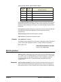
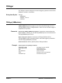
command). Table 2-2 provides a description of each tree relay function.
Table 2-2. Tree Relay Descriptions
Tree Relay
Channel Designation
Chapter 2
Functional Description
90
VSA
Connects the Voltage Sense H-L-G terminals
of the Analog Bus to the Bank A channels
(channels 00 to 31)
91
VSB
Connects the Voltage Sense H-L-G terminals
of the Analog Bus to the Bank B channels
(channels 32 to 63)
92
CS
Connects the Current Source H-L-G terminals
of the Analog Bus to the Bank B channels
(channels 32 to 63)
93
RTA
Connects the Reference Thermistor to Bank A
for voltage sense (4-wire resistance
measurement of the thermistor)
94
RTB
Connects the Reference Thermistor to Bank B
for current source (4-wire resistance
measurement of the thermistor)
Switchbox Applications 41
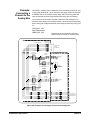
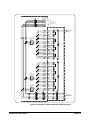
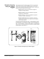
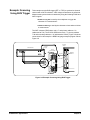
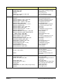
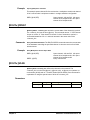
Example:
Connecting a
Channel to the
Analog Bus
Use CLOSe <channel_list> command to close a channel (channel 00 - 63)
or tree relay (channel 90 - 94). A channel or tree relay remains closed until
an OPEN is sent or the module is reset using *RST. Removing power will
open all channels and tree relays because the relays are non-latching.
You must close a tree relay to connect a channel to the analog bus. For
example, close channel 23 on module number 1 and connect it to the analog
bus by closing the voltage sense bank A tree relay (channel 90). See Figure
2-2.
CLOS(@123, 190)
Make measurement
OPEN(@123, 190)
E1476A 64-CHANNEL MULTIPLEXER
!Channel 90 can be left closed and other
!bank A channels closed for measurement
ANALOG BUS
FRONT PANEL
CONNECTOR
VOLTAGE SENSE BUS
H
L VM Input
G
TO E1411B OR
E1326B
MULTIMETER
H
L
G
CURRENT SOURCE BUS
100
VSA CH90
VOLTAGE SENSE
BANK A
TERMINAL MODULE
32
BANK A
CH00-CH31
32
H H
L L
G G
CHANNELS
00-31
H H
L L
G G
RTA CH93
(V SENSE)
5K OHM
REFERENCE
THERMISTOR
REF THERMISTER RELAYS
RTB CH94
(I SOURCE)
H H
L L
G G
VSB CH91
VOLTAGE SENSE
BANK B
32
BANK B
CH32-CH63
32
H H
L L
G G
CHANNELS
32-63
CS CH92
CURRENT SOURCE
BANK B
VOLTAGE SENSE BUS
ANALOG BUS
VM INPUT
H H
L L
G G
TO E1412A OR
EXTERNAL VM OR
OTHER DEVICE
H H
L L
G G
100
CURRENT SOURCE BUS
VM
Figure 2-2. Example: Connecting a Channel to the Analog Bus
42 Switchbox Applications
Chapter 2
Example: Two-Wire
Resistance
Measurements
This example illustrates three-wire switching and a method for making
accurate 2-wire resistance measurements. The E1476A analog bus
contains current-limiting protection resistors that can introduce
measurement error if the measuring instrument does not have a suitable
high impedance. This example describes a method to make measurements
that avoids the protection resistors.
Making two-wire measurements from the analog bus requires the internal
bus protection resistors which will introduce about 100 W per lead to the
resistance measurement. Use Channel 00 as the common terminals to
make two-wire measurements from channels 01 through 31 on bank A.
Close tree relays VSA and VSB (channels 90 and 91) to connect bank B
channels (32 through 63) to channel 00 through the bank A bus. You can
now make two-wire measurements from 63 channels using channel 00 as
the common. No current-limiting resistors are in the path. See Figure 2-3
for a circuit diagram. A typical program sequence is:
CLOS(@190, 191, 100)
CLOS(@1cc)
Make measurement
OPEN(@1cc)
Example: Four-Wire
Resistance
Measurements
!Closes all paths through channel 00
!"cc" = channel to be measured (01 to 63)
!Open channel cc after measurement is made
To make four-wire resistance measurements when switching (not
scanning), you must use a channel from bank A for the voltage sense and
close the voltage sense bank A tree relay (VSA). Also, you must use a
channel from bank B for the current source and you must close the current
source relay (CS) on bank B.
The VSA and CS relays connect the device under test to the analog bus.
Typically you pair the first channel of bank A with the first channel of bank
B (e.g. channels 00 and 32, 01 and 33, 02 and 34, etc.). See Figure 2-4 for
a circuit diagram. A typical program sequence follows.
NOTE
Using the SCAN command automatically pairs channels 00 and 32, 01 and
33, 02 and 34, etc. for four-wire measurements. See "Scanning
Applications".
CLOS(@100, 190, 132, 192) !Channels 100 and 132 are a 4-wire pair
Make measurement in four-wire mode
OPEN(@100, 132)
!Open measurement channels except tree
!relays
Chapter 2
Switchbox Applications 43
E1476A 64-CHANNEL MULTIPLEXER
VOLTAGE SENSE BUS
ANALOG BUS
FRONT PANEL
CONNECTOR
H
L VM Input
G
H
L
G
TO E1411B OR
E1326B
MULTIMETER
CURRENT SOURCE BUS
TERMINAL MODULE
H H
L L
G G
100
VSA CH90
VOLTAGE SENSE
BANK A
CH00
H H
L L
G G
CH07
H H
L L
G G
CH08
H H
L L
G G
CH15
2-WIRE
MEASUREMENT
COMMON
BANK A
VSB CH91
VOLTAGE SENSE
BANK B
CH16
H H
L L
G G
CH23
H H
L L
G G
CH24
H H
L L
G G
CH31
H H
L L
G G
CH32
H H
L L
G G
CH39
H H
L L
G G
CH40
H H
L L
G G
CH47
H H
L L
G G
CH48
H H
L L
G G
CH55
H H
L L
G G
CH56
H H
L L
G G
CH63
BANK B
CS CH92
CURRENT SOURCE
BANK B
VOLTAGE SENSE BUS
H H
L L
G G
ANALOG BUS
VM INPUT
H H
L L
G G
TO E1412A OR
EXTERNAL VM OR
OTHER DEVICE
H H
L L
G G
100
CURRENT SOURCE BUS
VM
Figure 2-3. Example: Two-Wire Resistance Measurements
44 Switchbox Applications
Chapter 2
E1476A 64-CHANNEL MULTIPLEXER
VOLTAGE SENSE BUS
ANALOG BUS
FRONT PANEL
CONNECTOR
H
L
G
VM Input
TO E1411B OR
E1326B
MULTIMETER
H
L
G
CURRENT SOURCE BUS
TERMINAL MODULE
H H
L L
G G
100
VSA CH90
VOLTAGE SENSE
BANK A
CH00
H H
L L
G G
CH07
H H
L L
G G
CH08
H H
L L
G G
CH15
H H
L L
G G
CH16
H H
L L
G G
CH23
H H
L L
G G
CH24
H H
L L
G G
CH31
VOLTAGE
SENSE
R
BANK A
H H
L L
G G
VSB CH91
VOLTAGE SENSE
BANK B
H H
L L
G G
CH39
H H
L L
G G
CH40
H H
L L
G G
CH47
H H
L L
G G
CH48
H H
L L
G G
CH55
H H
L L
G G
CH56
H H
L L
G G
CH63
ANALOG BUS
VM INPUT
H H
L L
G G
TO E1412A OR
EXTERNAL VM OR
OTHER DEVICE
H H
L L
G G
100
CURRENT SOURCE BUS
CURRENT
SOURCE
BANK B
CS CH92
CURRENT SOURCE
BANK B
VOLTAGE SENSE BUS
CH32
VM
Figure 2-4. Example: Four-Wire Resistance Measurements
Chapter 2
Switchbox Applications 45
Example:
Temperature
Measurements
The E1476A allows you to make temperature measurements from any
channel of the multiplexer. A 5 KW reference thermistor is provided on the
E1476A terminal module. You measure the resistance of this reference
thermistor to calculate the temperature of the thermocouple junctions
within the terminal module to compensate thermocouple temperature
measurements.
Temperature measurements using thermistors consist of 2-wire or 4-wire
ohms measurements.Thermocouple measurements are compensated by
the thermistor on the E1476A terminal module. The temperature of the
thermocouple lead junctions inside the terminal module affects the
temperature reading taken from a thermocouple. Use the thermistor on the
terminal module to determine the temperature inside the terminal module
and to compensate the thermocouple temperature measurements.
This example shows one way to make temperature measurements using
an E1412A or equivalent multimeter. See Figure 2-5 for typical connections.
See Chapter 3 to make temperature measurements with the E1326 or
E1411 multimeters.
E1476A 64-CHANNEL MULTIPLEXER
ANALOG BUS
FRONT PANEL
CONNECTOR
VOLTAGE SENSE BUS
H
L
G
VM Input
TO E1411B OR
E1326B
MULTIMETER
H
L
G
CURRENT SOURCE BUS
100
VSA CH90
VOLTAGE SENSE
BANK A
TERMINAL MODULE
32
BANK A
CH00-CH31
THERMOCOUPLE
H H
L L
G G
H H
L L
G G
RTA CH93
(V SENSE)
5K OHM
REFERENCE
THERMISTOR
REF THERMISTER RELAYS
RTB CH94
(I SOURCE)
H H
L L
G G
VSB CH91
VOLTAGE SENSE
BANK B
32
BANK B
CH32-CH63
H H
L L
G G
CS CH92
CURRENT SOURCE
BANK B
VOLTAGE SENSE BUS
ANALOG BUS
VM INPUT
H H
L L
G G
TO E1412A OR
EXTERNAL VM OR
OTHER DEVICE
H H
L L
G G
CURRENT SOURCE BUS
100
VM
THERMOCOUPLE
H
L
G
Jumper Low to Guard
to eliminate measurement
errors
Figure 2-5. Example: Temperature Measurements
46 Switchbox Applications
Chapter 2
The procedure to make temperature measurements is:
1 Measure the resistance of the 5 KW thermistor on the terminal module
(Thr_ohms). A 4-wire ohms measurement should be made to avoid
measurement errors by the 100W protection resistors (see "Example:
Four-Wire Resistance Measurements").
2 Compute the temperature of the terminal module (Tref) from the
reading (Thr_ohms). For values of resistance between 92.7 W to
3.685E6 W, use the following equation to calculate the temperature
of the terminal module, where Tref = temperature in degrees C and
Thr_ohms = the resistance of the 5 KW thermistor, W = ln (Thr_ohms),
A = 1.28463E-3, B = 0.23625E-3, and C = 9.2697E-8.
Tref = { 1/(A + W * (B + C * W * W)) } - 273.15
3 Measure voltage on the thermocouple connected to a channel (Vt).
4 Compute the effective temperature at the external thermocouple
junction by doing the following two steps:
• Compute the actual voltage across the external thermocouple
junction using VtcTexternal = Vmeter - VtcTref whereVmeter is the
actual voltmeter reading and VtcTref is the voltage across the
selected thermocouple type at the terminal module temperature
(Tref). This voltage must be evaluated from tabular data for the
selected thermocouple.
• Evaluate the actual thermocouple temperature using the
VtcTexternal value and the tabular data for the selected
thermocouple.
5 Compute the compensated voltage (V) by the formula: V = (Vt-Vref).
6 Convert the compensated voltage (V) calculated in Step 4 to
temperature. This is the actual temperature measured by the
thermocouple.
Chapter 2
Switchbox Applications 47
Scanning Applications
This section provides some example applications to make measurements
using the scanning method, including:
• Scanning Channels Using the Analog Bus
• Example: Scanning Using TTL VXIbus Triggers
• Example: Scanning Using BUS Trigger
• Example: Using the Scan Complete Bit
Scanning Channels
Using the Analog
Bus
Scanning a multiplexer channel consists of closing the channel and its
associated bank analog bus tree relay. You can make a single scan through
the channel list or scan a multiple number of times. You also can scan the
channel list continuously until the scan is aborted. Figure 2-6 shows the
commands in the scan sequence.
ARM:COUN <
>
TRIG:SOUR BUS|HOLD|EXT|IMM|
TTLT|ECLT
OUTP[:EXT] 1|O|ON|OFF
OUTP:ECTL 1|O|ON|OFF
OUTP:TTLT 1|O|ON|OFF
INIT:CONT 1|0|ON|OFF
SCAN:MODE
NONE|VOLT|RES|FRES
SCAN:PORT ABUS
SCAN <
>
INIT
TRIG
Figure 2-6. Command Sequence to Scan Channels
48 Switchbox Applications
Chapter 2
The TRIGger:SOURce command specifies the source to advance the scan.
The OUTPut command can be used to enable the E1406 Command
Module's “Trig Out” port, TTL Trigger bus line (0-7) or ECL Trigger bus lines
(0-1).
You can scan a channel or a list of channels using the SCAN command.
The tree relays listed in Table 2-2 are automatically switched when you
specify the command SCAN:PORT ABUS. This command is required for the
tree relays to function during the scan through the channel list. The default
value is SCAN:PORT NONE which does not allow these relays to operate
and connect channels to the analog bus.
At power-on or after resetting the module with the *RST command,
connection to the analog bus is disabled for scan operations. You must
execute SCAN:PORT ABUS to enable analog bus tree relay (channels 90,
91 and 92) operation.
The analog bus provides access to all three wires of the channel (High, Low
and Guard). Access is through the front panel analog bus connector (usually
connected to other multiplexers or to the E1411B multimeter) or through the
terminal module “VM Input” and “VM WI” terminals.
NOTE
To scan modules in a switchbox, you must first form a valid "SWITCHBOX"
instrument. See Figure 2-1 for a typical switchbox configuration.
For multiple-module switchbox configurations, channels to be scanned can
extend across switch modules. For example, for a two-module switchbox
instrument, SCAN (@100:263) scans all channels of both multiplexer
modules.
Use ARM:COUNt <number> to set from 1 to 32767 scans. Use
INITiate:CONTinuous ON to set continuous scanning. Tree relays
(channels 90 through 94) are controlled automatically by the “SWITCH”
driver SCAN command when used in conjunction with SCAN:MODE or
SCAN:PORT ABUS.
Chapter 2
Switchbox Applications 49
Example: Scanning
Using TTL VXIbus
Triggers
This example uses the TTL VXIbus triggers (TTLT 0-7) to synchronize
channel closures with the E1412A 6-Digit Multimeter. A 2-wire ohms
measurement is performed. Measurement synchronization is attained by
using the following E1406 and E1412A signals.
• E1406 TTL Trig In is used by the multimeter to trigger the
multiplexer to change channels
• E1406 TTL Trig Out is used by the multiplexer to trigger the
multimeter for a measurement.
• E1412A TTL Ext Trig is used by the multiplexer to signal the
multimeter to initiate a measurement.
• E1412A TTL VM Complete used the multimeter to signal the
multiplexer that measurement is complete and the multiplexer
should change channels.
The E1412A multimeter GPIB select code = 7, primary address = 09 and
secondary address = 03 (addressed at 70903). The E1476A GPIB select
code = 7, primary address = 09 and secondary address = 14 (addressed at
70914). Figure 2-7 shows connections for this example. A BASIC language
example program follows Figure 2-7.
Command
Module
E1406A
Command Module
E1476A
Multiplexer Module
E1412A
Multimeter Module
E1412A
E1476A
Terminal Module
Trig
Trig
In
VM Complete
Trig
Out
E1476A
Multiplexer Modules
Figure 2-7. Example: Scanning Using TTL VXIbus Triggers
50 Switchbox Applications
Chapter 2
10
20
30
40
50
60
70
80
90
100
110
120
130
140
150
160
170
ASSIGN @Switchbox TO 70914
ASSIGN @Voltmeter TO 70903
DIM Results(1:64)
INTEGER Opc_value
OUTPUT @Voltmeter;"*RST;*CLS"
OUTPUT @Voltmeter;"CONF:RES"
OUTPUT @Voltmeter;"TRIG:SOUR TTLT2"
OUTPUT @Voltmeter;"OUTP:TTLT1 ON"
OUTPUT @Voltmeter;"TRIG:COUN 64"
OUTPUT @Voltmeter;"*OPC?"
ENTER @Voltmeter;Opc_value
OUTPUT @Voltmeter;"INIT"
OUTPUT @Switchbox;"*RST;*CLS"
OUTPUT @Switchbox;"OUTP:TTLT2 ON"
OUTPUT @Switchbox;"TRIG:SOUR TTLT1"
OUTPUT @Switchbox;"SCAN:MODE RES"
OUTPUT @Switchbox;"SCAN:PORT ABUS"
180
190
200
210
220
230
240
250
260
OUTPUT @Switchbox;"SCAN(@100:163)
OUTPUT @Switchbox;"*OPC?"
ENTER @Switchbox;Opc_value
OUTPUT @Switchbox;"INIT"
OUTPUT @Voltmeter;"FETC?"
ENTER @Voltmeter;Results(*)
PRINT Results(*)
OUTPUT @Switchbox;"*RST"
END
Chapter 2
!Assign switchbox logical address
!Assign multimeter logical address
!Dimension array for readings
!Reset multimeter, clear status system
!Configure for 2-wire Ohms
!Set multimeter to receive trigger from TTLT2
!Output VM Complete on TTLT1 line
!Accept 64 triggers
!Pause until multimeter is ready
!Fetch the *OPC? response
!Initialize multimeter; ser "wait-for-trigger"
!Reset switchbox, clear status system
!Enable switchbox trigger output TTLT2
!Set for TTLT1 trigger input
!Set multiplexer for 2-wire Ohms
!Enable analog bus tree relay control
!during scan
!Set 64-channel scan list
!Pause until switch is ready
!Fetch the *OPC? response
!Initialize multiplexer scan
!Transfer readings to output buffer
!Read all 64 readings from multimeter
!Print the Results array (all 64 readings)
!Reset multiplexer to open all channels
Switchbox Applications 51
Example: Scanning
Using BUS Trigger
This example uses the BUS trigger (GET or *TRG) to synchronize channel
closures with a 3457A voltmeter. A DC voltage measurement is performed.
Measurement synchronization is attained by using the following E1406 and
3457A signals.
• E1406 TTL Trig Out is used by the multiplexer to trigger the
voltmeter for a measurement.
• 3457A TTL Ext Trig is used by the voltmeter to know when to initiate
a measurement.
The 3457 voltmeter GPIB select code = 7 and primary address = 22
(addressed at 722). The E1476A GPIB select code = 7, primary address
= 09 and secondary address = 14 (addressed at 70914). Figure 2-8 shows
connections for this example. A BASIC language example program follows
Figure 2-8.
Command
Module
3457A Multimeter
External
Trigger
E1476A
Terminal Module
Trig Out
HI
Multiplexer
Module #1
LO
VM Input
Figure 2-8. Example: Scanning Using BUS Trigger
52 Switchbox Applications
Chapter 2
10
20
30
40
50
60
70
80
90
100
110
120
130
140
150
160
170
180
190
200
210
220
230
240
250
Chapter 2
ASSIGN @Switchbox TO 70914
ASSIGN @VM3457 TO 722
INTEGER Opc_value
OUTPUT @VM3457;"*RESET"
OUTPUT @VM3457;"TRIG EXT"
OUTPUT @VM3457;"DCV"
OUTPUT @VM3457;"MEM FIFO"
OUTPUT @Switchbox;"*RST;*CLS"
OUTPUT @Switchbox;"OUTP ON"
OUTPUT @Switchbox;"TRIG:SOUR BUS"
OUTPUT @Switchbox;"SCAN:MODE VOLT"
OUTPUT @Switchbox;"SCAN:PORT ABUS"
OUTPUT @Switchbox;"SCAN(@100:163)"
OUTPUT @Switchbox;"INIT"
OUTPUT @Switchbox;"*OPC?"
ENTER @Switchbox;Opc_value
ENTER @VM3457;Results
PRINT "Channel 0",Results
FOR Chan = 1 TO 63
OUTPUT @Switchbox;"*TRG"
ENTER @VM3457;Results
PRINT "Channel",Chan,Results
NEXT Chan
OUTPUT @Switchbox;"*RST"
END
!Assign switchbox logical address
!Assign voltmeter logical address
!Reset voltmeter
!Set voltmeter for external trigger
!Set voltmeter measurement mode
!Enable voltmeter reading memory mode
!Reset the multiplexer
!Enable the switchbox trigger output
!Set switchbox to be triggered by the bus
!Set switchbox to scan in voltage mode
!Enable ABUS tree switch control during scan
!Set scan list for all 64 channels
!Start the scan
!Pause until switchbox is set up
!Read response to *OPC? command
!Read the first voltmeter reading
!Print first reading
!Set up loop for other 63 channels
!Trigger switchbox to change channels
!Enter voltmeter measurement result
!Print results
!Loop back for next channel
!Reset the switchbox to open all channels
Switchbox Applications 53
Example: Using the
Scan Complete Bit
The scan complete bit (bit 8) can be used in the Operation Status Register
of the “SWITCHBOX” driver to determine when a scanning cycle completes.
Bit 8 has a decimal value of 256 and can be read directly with STAT:OPER?
command (see STATus:OPERation[:EVENt]? for an example).
The scan complete bit will be reported as bit 7 of the Status Register when
it is enabled by the STAT:OPER:ENAB 256 command. Use the GPIB Serial
Poll or the IEEE 488.2 Common Command *STB? to read the Status
Register.
This example monitors bit 7 in the Status Register to determine when the
scanning cycle completes. The example uses GPIB select code 7, primary
address 09 and secondary address 14 for the multiplexer (addressed at
70914).
10
20
30
40
50
60
70
80
90
OUTPUT 70914;"*CLS"
OUTPUT 70914;"STAT:OPER:ENAB 256"
OUTPUT 70914;"TRIG:SOUR EXT"
OUTPUT 70914;"SCAN(@100:163)"
OUTPUT 70914;"INIT"
WHILE NOT BIT(SPOLL(70914),7)
PRINT "Do other operations here"
END WHILE
END
54 Switchbox Applications
!Clear to talk to the switch
!Set so scan complete causes an event
!Set to external trigger mode
!Set scan list for 64 channels
!Start scanning cycle
!Loop unit bit 7 is set
!Do other operations until bit 7 is set
Chapter 2
Recalling and Saving States
This section contains information about saving and recalling multiplexer
states. The "SWITCHBOX" driver can store up to 10 states.
Saving States
The *SAV <numeric_state> command saves the current instrument state.
The state number (0-9) is specified in the numeric_state parameter. The
following settings are saved:
• Channel Relay State (channels 00 through 63 open or closed)
• Control Relay States (channels 90 through 94 open or closed)
• ARM:COUNt
• TRIGger:SOURce
• OUTPut[:STATe]
• INITiate:CONTinuous
• [ROUTe:]SCAN:MODE
• [ROUTe:]SCAN:PORT
Recalling States
NOTE
Chapter 2
The *RCL <numeric_state> command recalls a previously saved state.
Enter the number (0-9) in the numeric_state parameter of the desired saved
state. If *SAV was not previously executed using the selected number, the
multiplexer will configure to the reset values (see Table 2-1).
Scan lists are not saved when a state is saved. You must re-enter the
scan list after recalling a state.
Switchbox Applications 55
Detecting Error Conditions
There are two general approaches to error checking: polling and using
interrupts.
Using Polling
10
20
30
40
50
60
70
80
90
The simplest, but most time consuming, is to ask the instrument whether
there are errors at every step of the switching process. This is called “polling”
and is illustrated in the following example.
DIM Err$[256]
OUTPUT 70914;"CLOS(@101)"
OUTPUT 70914;"SYST:ERR?"
ENTER 70914;Err$
IF VAL (Err$) > 0 THEN
PRINT "Error";Err$
STOP
END IF
... (PROGRAM CONTINUES)
Using Interrupts
The second approach to error checking involves the use of interrupts. The
following program is a method of checking for errors using interrupts as you
program the multiplexer. The program monitors the multiplexer's Standard
Event Status Register for an error condition. If no errors occur, the
multiplexer functions as programmed. If errors do occur, the multiplexer
interrupts the computer, and the error codes and messages are read from
the error queue.
10 !Add your application's code here
.
100 ON INTR 7 CALL Errmsg
110 ENABLE INTR7:2
210 OUTPUT 70914;"*SRE 32"
220 OUTPUT 70914;"*ESE 60"
230 !Add your application's code here
.
300 END
310 !Define interrupt service routine
320 SUB Errmsg
330 DIM A$[256]
340 CLEAR 70914
350 B = SPOLL(70914)
360 REPEAT
370
OUTPUT 70914;"SYST:ERR?"
380
ENTER 70914;Code,A$
390
PRINT Code,A$
400 UNTIL Code=0
410 OUTPUT 70914;"*CLS"
420 STOP
430 SUBEND
56 Switchbox Applications
!Close channel 1
!Query for error
!Read response
!If an error is found (Err$ not 0)
!Print the error
!Quit if error encountered
!Call to print out error message
!Add your application's code here
!Enable the standard event summary bit SRE
!Enable all parser-generated errors
!Declare response string
!Clear the multiplexer
!Fetch status byte
!Repeat
!Query for error
!Read response
!Print error
!Query for an error until error code = 0
!Clear status registers and error queue
Chapter 2
Chapter 3
Scanning Voltmeter Applications
Using This Chapter
This chapter provides application information and examples to use the
E1476A 64-Channel, 3-Wire Multiplexer module (multiplexer) in a
"scanning voltmeter" configuration, including:
• Scanning Voltmeter Description . . . . . . . . . . . . . . . . . . . . . . . .57
• Scanning Voltmeter Measurements . . . . . . . . . . . . . . . . . . . . .60
• Scanning Voltmeter Commands Quick Reference . . . . . . . . . .62
NOTE
The commands to use the E1476A in scanning voltmeter configuration are
different than the commands to use the E1476A in switchbox configuration.
See Chapter 4 for switchbox configuration commands. See "Scanning
Voltmeter Commands Quick Reference" in this chapter for scanning
voltmeter configuration commands.
Scanning Voltmeter Description
A scanning voltmeter configuration uses the voltmeter instrument driver
“VOLTMTR”. The scanning voltmeter commands are different from the
switchbox commands listed in Chapter 4. A scanning voltmeter uses
the commands in the E1326B/E1411B 5-Digit Multimeter User's Manual
to control the switches and make measurements. See Figure 3-1 for a
typical scanning voltmeter configuration.
Command
Module
Card Number 00
1
2
4
8
16
32
64
128
E1411A/B Multimeter
Logical Address = 24
Secondary Address = 03
128
64
32
16
8
4
2
1
Card Number 01
Multiplexer Number 1
Logical Address = 25
128
64
32
16
8
4
2
1
Card Number 02
Multiplexer Number 2
Logical Address = 26
Figure 3-1. Typical Scanning Voltmeter Configuration
Chapter 3
Scanning Voltmeter Applications 57
Measurement Types
For scanning voltmeter configuration, you can make measurements with
the E1411 (or E1326 used with a C-size adapter installed in the C-size
mainframe) 5½-Digit Multimeter. The E1476A can be used with the
multimeter to measure voltage, resistance or temperature. The multimeter
used must be an E1411 (or E1326 used with a C-size adapter installed in
the C-size mainframe). The device driver for these two multimeters controls
switches in the scan mode.
Tree Relays
The scanning voltmeter can be configured to perform voltage, 2-wire ohms,
4-wire ohms or temperature measurements via the multiplexer internal
analog bus. The E1326/E1411 multimeter automatically controls the
channels and tree relays when you use the MEASure or CONFigure
commands. See Table 3-1 for tree relays.
Table 3-1. Tree Relay Descriptions
Function
Analog Bus
Relays
Reference
Thermistor
Relays
Channel
Designation
Description
90
VSA
Connects the Voltage Sense H-L-G
terminals of the Analog Bus to Bank A.
91
VSB
Connects the Voltage Sense H-L-G
terminals of the Analog Bus to Bank B.
92
CS
Connects the Current Source H-L-G
terminals of the Analog Bus to Bank B.
93
RTA
Connects the Reference Thermistor to
Bank A for voltage sense.
94
RTB
Connects the Reference Thermistor to
Bank B for current source.
Device Drivers
The scanning voltmeter configuration does not use the “SWITCH” switchbox
device driver so you cannot use the switchbox command reference in
Chapter 4. Instead, you use the “VOLTMTR” device driver and the E1411B
multimeter command reference. The multimeter's command quick reference
from the E1326/E1411 5½-Digit Multimeter User's Manual is provided at the
end of this chapter for your convenience. See the multimeter manual for
detailed descriptions of the commands.
The Analog Bus
The analog bus provides access to all three wires of the channel (High, Low
and Guard). Access is through the front panel analog bus connector which
is used to connect to other multiplexers and to the E1411 (or E1326)
multimeter. See Figure 1-1 in Chapter 1 for a schematic representation of
the scanning voltmeter using the E1411B multimeter with an E1476A
multiplexer. The analog bus is connected from multiplexer to multiplexer in
multiple-module scanning voltmeter instruments to provide a continuous bus
for the instrument.
58 Scanning Voltmeter Applications
Chapter 3
Reset Conditions
This section describes the power-on and reset condition the E1476A
multiplexer module is in when a “scanning voltmeter” reset occurs. The
“VOLTMTR” device driver controls both the voltmeter and any switch
module configured with it in a scanning voltmeter configuration.
At power-on or following the reset of a scanning voltmeter (*RST command
sent to the voltmeter address), all 64 channels and all tree relays are open.
In addition, after a *RST command, the current scan channel list is
invalidated. See the E1326/E1411 User's Manual for the reset conditions
of the multimeter.
Table 3-2 lists the parameters and default values for the multiplexer module
functions following power-on or reset. These are not accessible to you via
the “VOLTMTR” driver, but are provided so you will know the multiplexer
module condition after power-on or following a reset.
Table 3-2. E1476A Default Conditions for Power-on and Reset
Parameter
Chapter 3
Default
Description
ARM:COUNt
1
Number of scanning cycles is one.
TRIGger:SOURce
IMM
Advances through a scanning list
automatically.
INITiate:CONTinuous
OFF
Number of scanning cycles is set
by ARM:COUNt
OUTPut[:STATe]
OFF
Trigger output from EXT, TTL, or
ECL sources is disabled.
[ROUTe:]SCAN:MODE
NONE
Channel list is set for volts
measurement.
[ROUTe:]SCAN:PORT
NONE
Analog bus connections are
disabled from channels.
Channel state
All 64 channels are open (channels 00 - 63)
Tree relay state
All tree relays are open (channels 90 - 94)
Channel list from SCAN
command (after *RST)
Current channel list is invalidated following a
reset of the module with *RST command.
Scanning Voltmeter Applications 59
Scanning Voltmeter Measurements
This section provides an example program for making voltage, 2-wire ohms,
4-wire ohms and thermocouple or thermistor temperature measurements
with a scanning voltmeter configuraton. The multimeter (E1326/E1411)
MEASure command is used to specify the channel list to scan and to
make measurements.
Configuring the
Scanning Voltmeter
To do this example, you will need the following items. See Figure 3-2 for
equipment configuration.
• E1411B multimeter
• E1476A multiplexer
• 2.5 inch Analog Bus cable (E1400-61605)
• Zero Ohm jumpers (such as paper clips)
• Resistors (any value)
Analog Bus Cable
(E1400-61605)
Command
Module
E1411B
ANALOG
BUS
E1411B
Multimeter
E1476A
Multiplexer
E1476A
Multiplexer Module
Figure 3-2. Scanning Voltmeter Equipment Configuration
Since the E1411B multimeter and E1476A multiplexer form a scanning
voltmeter configuration, the E1476A must have a logical address that is
sequential to the E1411B. Also, the E1411B must be at an instrument
address (logical address divisible by 8). Set the E1411B to logical address
24 (secondary address is 24/8 = 03) and the E1476A to logical address 25.
The modules must be installed in adjacent slots with the multiplexer to the
right of the multimeter. The scanning voltmeter is addressed from GPIB
interface 7 (or the interface you use instead of 7), primary address 09 and
secondary address 03. The scanning voltmeter address is 70903 and the
multimeter controls the multiplexer module.
60 Scanning Voltmeter Applications
Chapter 3
As required, set the E1411B multimeter to logical address 24 and the
E1476A multiplexer to logical address 25. Next, install the instruments in
the mainframe and connect the Analog Bus cable between the E1411B
multimeter and the E1476A multiplexer. Then, connect resistors and/or
Zero Ohm jumpers to desired channels (between 0 and 31) on the terminal
module.
Programming the
Scanning Voltmeter
When the configuration is complete, turn mainframe power ON and verify
that the "VOLTMETR" driver version A.06.00 is installed in the E1406
Command Module (see Exercise 1 in Chapter 1). If the appropriate
"VOLTMETR" driver is installed, run the following program.
This example scans 32 multiplexer channels and makes a measurement on
each channel. The measured readings are entered into the computer and
displayed after the scan. Table 3-3 shows how to modify the program to
make voltage, 2-Wire Ohms, 4-Wire Ohms, Thermocouple, and Thermistor
measurements.
NOTE
10
20
30
40
For the example program, when the multimeter buffer fills, measurements
are suspended until readings are read from the buffer (by the computer) to
make space available.
DIM Rdgs(1:32)
CLEAR 70903
OUTPUT 70903;"*RST"
OUTPUT 70903;"MEAS:VOLT:DC?(@100:131)"
50 ENTER 70903;Rdgs(*)
60 PRINT Rdgs(*)
70 END
! Dimension array to store readings
! Clear the scanning voltmeter
! Reset the scanning voltmeter
! Configure the multimeter for DC voltage
! measurements and specify channel list
! to scan (channels 00 through 31)
! Enter measured readings
! Display measured readings
Table 3-3. Changes to Example Program
For This
Measurement:
Change Line 40 to:
Comments
Voltage
N/A
2-Wire Ohms
40 OUTPUT 70903;"MEAS:RES? (@100:131)"
4-Wire Ohms
40 OUTPUT 70903;"MEAS:FRES? (@100:131)"
Channels 32 - 63 are automatically
paired with channels 00 - 31 for
4-wire measurements.
Thermocouple
Temperature
40 OUTPUT 70903; "MEAS:TEMP? TC,K,(@100:131)"
Type K thermocouple temperature
measurements.
Thermistor
Temperature
40 OUTPUT 70903;"MEAS:TEMP? FTH,5000,(@100:131)" 4-wire, 50009 thermistor temperature
measurements.
Chapter 3
Line 40 performs a DCV measurement
Scanning Voltmeter Applications 61
Scanning Voltmeter Command Quick Reference
The following tables summarize SCPI commands for the E1326/E1411
multimeters. See the E1326/E1411 User’s Guide for details.
Command
ABORt
Description
Place multimeter in idle state
CALibration
:LFRequency 50 | 60 | MIN | MAX
:LFRequency? [MIN | MAX]
:ZERO:AUTO OFF | 0 | ON | 1
:ZERO:AUTO?
Change line reference frequency
Query line reference frequency
Enable/disable autozero mode
Query autozero mode.
CONFigure
:FRESistance [<range>[,<resolution>]] [,<channel_list>]
:RESistance [<range>[,<resolution>]] , <channel_list>
:TEMPerature <transducer>,<type>,<channel_list>
:VOLTage:AC [<range> [,<resolution>]] [,<channel_list>]
:VOLTage[:DC] [<range> [,<resolution>]]
[,<channel_list>]
Configure multimeter for 4-wire ohms
Configure multimeter for 2-wire ohms
Configure multimeter for temperature
Configure multimeter for AC voltage
Configure multimeter for DC voltage
CONFigure?
Query multimeter configuration
DIAGnostic
:FETS <mode>
:FETS?
Selects control of FET multiplexers
Query mode of operation
DISPlay
:MONitor:CHANnel <channel> | AUTO
:MONitor:CHANnel?
:MONitor[:STATe] OFF | 0 | ON | 1
:MONitor[:STATe]?
Monitor multiplexer channel
Query monitor channel
Enable/disable monitor mode
Query monitor mode
FETCh?
FORMat
Place stored readings in output buffer
[:DATA] <type>[,<length>]
FORMat?
Select output data format and length
Query format
INITiate
[:IMMediate]
Place multimeter in wait-for trigger state
MEASure
:FRESistance? [<range>[,<resolution>]] [,<channel_list>]
:RESistance? [<range>[,<resolution>]], <channel_list>
:TEMPerature? <transducer>,<type> [,<channel_list>]
:VOLTage:AC? [<range> [,<resolution>]]
[,<channel_list>]
:VOLTage[:DC]? [<range> [,<resolution>]]
[,<channel_list>]
Make 4-wire ohms measurements
Make 2-wire ohms measurements
Make temperature measurements
Make AC voltage measurements
Make DC voltage measurements
MEMory
:VME:ADDRess <address>
:VME:ADDRess? [MIN | MAX]
:VME:SIZE <bytes>
:VME:SIZE? [MIN | MAX]
:VME:STATe <mode>
:VME:STATe?
Set address of memory on VME card.
Query VME memory location (address)
.Amount of memory used on VME card
Query amount of VME memory used
Direct readings to VME memory card
Query VME memory mode
OUTPut
TTLTrg0 | 1 | 2 | 3 | 4 | 5 | 6 | 7 [:STATe] OFF | 0 | ON | 1
:TTLTrg0 | 1 | 2 | 3 | 4 | 5 | 6 | 7 [:STATe]?
Send VM compl to VXIbus trigger lines
Query voltmeter complete destination
READ?
62 Scanning Voltmeter Applications
Place multimeter in wait-for trigger state
Place readings in output buffer
Chapter 3
Command
Description
SAMPle
:COUNt 1-16777215 | MIN | MAX
:COUNt? [MIN | MAX]
:SOURce IMM | TIM
:SOURce?
:TIMer 76 ms - 65,534 ms | MIN | MAX
:TIMer? [MIN | MAX]
Set number of readings per trigger
Query number of readings per trigger
Set pacing source
Query pacing source
Define period between readings
Query period between readings
[SENSe:]
FUNCtion[:<function>]
FUNCtion?
RESistance:APERture <time> | MIN | MAX
RESistance:APERture? [MIN | MAX]
RESistance:NPLC <number> | MIN | MAX
RESistance:NPLC? [MIN | MAX]
RESistance:OCOMpensated OFF | 0 | ON | 1
RESistance:OCOMpensated?
RESistance:RANGe <range> | MIN | MAX
RESistance:RANGe? [MIN | MAX]
RESistance:RANGe:AUTO OFF | 0 | ON | 1
RESistance:RANGe:AUTO?
RESistance:RESolution <resolution> | MIN | MAX
RESistance:RESolution? [MIN | MAX]VOLTage:AC:
RANGe <range> | MIN | MAX
VOLTage:AC:RANGe? [MIN | MAX]
VOLTage:APERture <time> | MIN | MAX
VOLTage:APERture? [MIN | MAX]
VOLTage[:DC]:RANGe <range> | MIN | MAX
VOLTage[:DC]:RANGe? [MIN | MAX]
VOLTage:NPLC <number> | MIN | MAX
VOLTage:NPLC? [MIN | MAX]
VOLTage:RANGe:AUTO OFF | 0 | ON |
1VOLTage:RANGe:AUTO?
VOLTage:RESolution <resolution>
VOLTage:RESolution? [MIN | MAX]
Select measurement function
Query measurement function
Set aperture (integration) time in sec
Query aperture (integration) time
Set integration time in PLCs
Query integration time
Enable/disable offset compensation
Query offset compensation mode
Select range
Query range
Enable/disable autorange function
Query autorange mode
Specify resolution
Query resolution
Select measurement range
Query range
Set aperture (integration) time in sec
Query aperture (integration) time
Select range
Query range
Set integration time in PLCs
Query integration time
Enable/disable autoranging
Query autorange mode
Specify resolution
Query resolution
SYSTem
:CDEScription? <card_number>
Return description of multiplexer in
scanning multimeter
Return card type of multiplexer in
scanning multimeter
Return error number/message from
error queue
:CTYPe? <card_number>
:ERRor?
TRIGger
:COUNt 1-16777215 | MIN | MAX
:COUNt? [MIN | MAX]
:DELay 0-16.777215 | MIN | MAX
:DELay? [MIN | MAX]
:DELay:AUTO OFF | 0 | ON | 1
:DELay:AUTO?
[:IMMediate]
:SOURce BUS | EXT | HOLD | IMM | TTLTrg0-TTLTrg7
:SOURce?
Chapter 3
Set number of triggers or scans
Query trigger count
Set delay between trigger and start of
measurement
Query trigger delay
Enable/disable automatic trigger delay
Query automatic trigger delay mode
Trigger immediately
Specify trigger source
Query trigger source
Scanning Voltmeter Applications 63
Command
*RST
Title
Reset
Description
Sets the multimeter and associated multiplexers. Sets:
FUNC:VOLT:DC
APER 16.7 ms|20 ms
CAL:ZERO:AUTO ON
NPLC 1
VOLT:RANG 8V
VOLT:RES 7.629 mV
RANGE:AUTO ON
RES:RANG 16384 W
RES:RES 15.6m W
RES:COMP OFF
TRIG:COUN 1
TRIG:DELAY:AUTO ON
TRIG:SOUR IMM
SAMP:COUN 1
SAMP:SOUR IMM
SAMP:TIM 200 ms
*TRG
Bus Trigger
When the multimeter is in the wait-for-trigger state and the trigger source is
TRIGger:SOURce BUS, use the *TRG command to trigger the multimeter.
*TST*
Self-Test
Should return 0. If code 1, 2, 3, or 4 occurs, return the multimeter to Agilent
Technologies for repair.
64 Scanning Voltmeter Applications
Chapter 3
Chapter 4
Switchbox Command Reference
Using This Chapter
This chapter describes Standard Commands for Programmable Instruments (SCPI)
and summarizes IEEE 488.2 Common (*) commands applicable to the E1476A
64-Channel 3-Wire Relay Multiplexer module when used in the switchbox
configuration, including:
• Command Types . . . . . . . . . . . . . . . . . . . . . . . . . . . . . . . . . . . 65
• SCPI Command Reference . . . . . . . . . . . . . . . . . . . . . . . . . . . 67
• SCPI Command Quick Reference . . . . . . . . . . . . . . . . . . . . . . 96
• IEEE 488.2 Common Command Reference . . . . . . . . . . . . . . 97
Command Types
Commands are separated into two types: IEEE 488.2 Common Commands and
SCPI Commands.
Common
Commands
Format
The IEEE 488.2 standard defines the common commands that perform functions
such as reset, self-test, status byte query, and so on. Common commands are four
or five characters in length, always begin with the asterisk character (*), and may
include one or more parameters. The command keyword is separated from the first
parameter by a space character. Some examples of common commands are shown
below:
*RST *ESR 32 *STB?
SCPI
Command
Format
The SCPI commands perform functions like closing switches, making
measurements, and querying instrument states or retrieving data. A subsystem
command structure is a hierarchical structure that usually consists of a top level (or
root) command, one or more lower level commands, and their parameters. The
following example shows part of a typical subsystem:
[ROUTe:]
CLOSe <channel_list>
SCAN <channel_list>
:MODE?
[ROUTe:] is the root command, CLOSe and SCAN are second level commands with
parameters, and :MODE? is a third level command.
Chapter 4
Switchbox Command Reference 65
Command
Separator
A colon (:) always separates one command from the next lower level command as
shown below:
ROUTe:SCAN:MODE?
Colons separate the root command from the second level command (ROUTe:SCAN)
and the second level from the third level (SCAN:MODE?).
Abbreviated
Commands
The command syntax shows most commands as a mixture of upper and lower case
letters. The upper case letters indicate the abbreviated spelling for the command.
For shorter program lines, send the abbreviated form. For better program readability,
you may send the entire command. The instrument will accept either the abbreviated
form or the entire command.
For example, if the command syntax shows MEASure, then MEAS and MEASURE are
both acceptable forms. Other forms of MEASure, such as MEASU or MEASUR will
generate an error. You may use upper or lower case letters. Therefore, MEASURE,
measure, and MeAsUrE are all acceptable.
Implied
Commands
Implied commands are those which appear in square brackets ([ ]) in the command
syntax. (The brackets are not part of the command and are not sent to the
instrument.) Suppose you send a second level command but do not send the
preceding implied command. In this case, the instrument assumes you intend to use
the implied command and it responds as if you had sent it. Examine the partial
[ROUTe:] subsystem shown below:
[ROUTe:]CLOSe <channel_list>
CLOSe? <channel_list>
OPEN <channel_list>
OPEN? <channel_list>
SCAN <channel_list>
:MODE <mode>
:MODE?
The root command [ROUTe:] is an implied command. To close relays in a
<channel_list>, you can send either of the following command statements:
ROUT:CLOS (@100:107, 201, 225)
or CLOS (@100:107, 201, 225)
These commands function the same closing channels 00 through 07 on card 1 and
channels 01 and 25 on card 2.
66 Switchbox Command Reference
Chapter 4
Parameters
Parameter Types. The following table contains explanations and examples of
parameter types you might see later in this chapter.
Table 4-1.
Parameter Type
Explanations and Examples
Numeric
Accepts all commonly used decimal representations of
number including optional signs, decimal points, and scientific
notation. 123, 123E2, -123, -1.23E2, .123, 1.23E-2,
1.23000E-01. Special cases include MINimum, MAXimum,
and DEFault.
Boolean
Represents a single binary condition that is either true or false
(ON, OFF, 1, 0)
Discrete
Selects from a finite number of values. These parameters use
mnemonics to represent each valid setting. An example is the
TRIGger:SOURce <source> command where source can be
BUS, EXT, HOLD, or IMM.
Optional Parameters. Parameters shown within square brackets ([ ]) are optional
parameters. (the brackets are not part of the command and are not sent to the
instrument.) If you do not specify a value for an optional parameter, the instrument
chooses a default value. For example, consider the ARM:COUNt?[<MIN | MAX>]
command.
If you send the command without specifying a parameter, the present ARM:COUNt
setting is returned. If you send the MIN parameter, the command returns the
minimum count available. If you send the MAX parameter, the command returns the
maximum count available. Be sure to place a space between the command and the
parameter.
Linking
Commands
Linking IEEE 488.2 Common Commands with SCPI Commands. Use a semicolon
between the commands. For example, *RST;OUTP ON or TRIG:SOUR HOLD;*TRG.
Linking Multiple SCPI Commands. Use both a semicolon and a colon between the
commands. For example, ARM:COUN1;:TRIG:SOUR EXT.
SCPI Command Reference
This section describes the Standard Commands for Programmable Instruments
(SCPI) commands for the E1476A Multiplexer module. Commands are listed
alphabetically by subsystem and within each subsystem.
There are two ways to send commands to the instrument. The most often used way
is from a controller over the GPIB interface. This method is called the “GPIB
interface” in the command reference. The second way is to send commands is from
a terminal connected to the E1406 command module (RS-232). Commands sent this
way are referred to as “from the terminal” in the command reference.
Chapter 4
Switchbox Command Reference 67
ABORt
The ABORt command stops a scan in progress when the trigger sources are either
TRIGger:SOURce BUS or TRIGger:SOURce HOLD. See the comments to stop a
scan if trigger source is not BUS or HOLD.
Subsystem Syntax
ABORt
• Channel Status After an ABORt: Aborting a scan will leave the last channel
Comments
it closed in the closed position.
• Effect on Scan Complete Status Bit: Aborting a scan will not set the “scan
complete” status bit.
Stopping Scans Enabled from GPIB Interface: When a scan is enabled from the GPIB
interface, and the trigger source is not HOLD or BUS, you can clear the interface to
stop the scan. In the BASIC programming language, this is done by executing the
CLEAR command for your interface (CLEAR 7, for example).
When the scan is enabled from the GPIB interface and the trigger source is
TRIGger:SOURce BUS or TRIGger:SOURce HOLD, send the ABORt command
over the GPIB bus.
Note
Clearing the GPIB interface during a scan leaves the last channel the scan
closed in the closed position and does not set the “scan complete” status
bit.
Stopping Scans by using the terminal: You may use a terminal connected to the
E1406 Command Module to stop any scan.
If the scan was started from the terminal, and the trigger source is HOLD or BUS,
send the ABORt command to halt the scan. If the scan was started from the terminal
and some other trigger source is being used, Ctrl+c will send an interface CLEAR
to the instrument and abort the scan. Sending Ctrl+r also sends an interface CLEAR
to the instrument and additionally performs a reset (*RST) on the instrument. (See
the E1406 Command Reference for details on the terminal interface.)
If the scan was started from the GPIB interface, but you want to stop it by using the
terminal, first make sure that the correct instrument (e.g., SWITCH at desired logical
address) is selected by using the terminal soft keys. Then send a Ctrl+r. This will
send an interface CLEAR to the GPIB task, but will not place the instrument in the
reset state with respect to the GPIB task. These actions will occur regardless of the
trigger source setting.
68 Switchbox Command Reference
Chapter 4
Note
Clearing the interface using a Ctrl+c from the terminal during a scan leaves
the last channel it closed in the closed position and does not set the “scan
complete” status bit.
Related Commands: ARM, INITiate:CONTinuous, [ROUTe:]SCAN, TRIGger
Example
Stopping a Scan with ABORt
TRIG:SOUR BUS
INIT:CONT ON
SCAN (@100:115)
INIT
.
.
ABOR
Chapter 4
Bus is trigger source
Set continuous scanning
Set channel list
Start scanning cycle
Abort scan in progress
Switchbox Command Reference 69
ARM
The ARM subsystem allows a scan list to be scanned multiple times
(1 through 32,767) with one INITiate command.
Subsystem Syntax
ARM
:COUNt <number> MIN|MAX
:COUNt? [<MIN|MAX>]
ARM:COUNt
ARM:COUNt <number> MIN|MAX allows scanning cycles to occur a
multiple of times (1 to 32,767) with one INITiate command when
INITiate:CONTinuous OFF|0 is set. MIN sets 1 cycle and MAX sets
32,767 cycles.
Parameters
Comments
Name
Type
Range of Values
Default Value
<number>
numeric
1 - 32,767 | MIN | MAX
1
Number of Scans: Use only values between 1 (MIN) to 32767 (MAX) for the number
of scanning cycles.
Related Commands: ABORt, INITiate[:IMMediate], INITiate:CONTinuous
*RST Condition: ARM:COUNt1
Example
Setting Ten Scanning Cycles
ARM:COUN 10
SCAN (@100:115)
INIT
Set 10 scanning cycles
Set channel list
Start scanning cycle
ARM:COUNt?
ARM:COUNt? [<MIN|MAX>] returns the current number of scanning cycles set by
ARM:COUNt. If a value between MIN and MAX is set, that value for ARM:COUNt is
returned.
The optional parameters MIN and MAX allow you to query the module for these
values instead of looking them up in the command reference. “1” is returned for the
MIN parameter. “32767” is returned for the MAX parameter, regardless of the
ARM:COUNt value set.
70 Switchbox Command Reference
Chapter 4
Parameters
Comments
Example
Name
Type
Range of Values
Default Value
<MIN | MAX>
numeric
MIN = 1, MAX = 32,767
current cycles
Related Commands: INITiate[:IMMediate]
Query Number of Scanning Cycles
ARM:COUN 55
ARM:COUN?
Chapter 4
Set 10 scanning cycles
Query number of scanning cycles;
returned value is 55
Switchbox Command Reference 71
DISPlay
The DISPlay subsystem monitors the channel state of a selected module (or card)
in a switchbox. The DISPlay command subsystem only operates with a RS-232
terminal connected to an E1406 Command Module RS-232 port. These commands
control the display on the terminal and would, in most cases, be typed directly from
the terminal keyboard.
However, it is possible to send these commands over the GPIB interface, and control
the terminal's display. In this case, care must be taken that the instrument receiving
the DISPlay command is the same one that is currently selected on the terminal.
Otherwise, the GPIB command will have no visible affect.
Subsystem Syntax
DISPlay
:MONitor
:CARD <number> | AUTO
:CARD?
[:STATe] <mode>
[:STATe]?
DISPLay:MONitor:CARD
DISPlay:MONitor:CARD <number> | AUTO selects the module in a switchbox to be
monitored. You must use DISP:MON:STAT ON to actually display the monitored
module state to the RS-232 terminal.
Parameters
Comments
Name
Type
Range of Values
Default Value
<number> | AUTO
numeric
1 - 99
AUTO
Selecting a Specific Module to be Monitored: Send the card number in a switchbox
with the DISPlay:MONitor:CARD command.
Selecting the Present Module to be Monitored: Use the DISPlay:MONitor:CARD
AUTO command to select the last module addressed by a switching command
([ROUTe:]CLOSe, for example).
*RST Conditions: DISPlay:MONitor:CARD AUTO
Example
Select Module #2 in a Switchbox for Monitoring
DISP:MON:CARD 2
72 Switchbox Command Reference
Select module #2 in a switchbox
Chapter 4
DISPLay:MONitor:CARD?
DISPlay:MONitor:CARD? queries the setting of the DISPlay:MONitor:CARD
command and returns the module in a switchbox to be monitored.
DISPLay:MONitor[:STATe]
DISPlay:MONitor[:STATe] <mode> turns the monitor mode ON or OFF. When
monitor mode is on, the RS-232 terminal display presents an array of values
indicating the open/close state of every switch on the module. This display is
dynamically updated each time a switch is opened or closed.
Parameters
Comments
Name
Type
Range of Values
Default Value
<mode>
boolean
ON | OFF | 1 | 0
OFF | 0
Monitoring Switchbox Channels: DISPlay:MONitor:STATe ON or
DISPlay:MONitor:STATe 1 turns the monitor mode ON to show the channel state of
the selected module. DISPlay:MONitor:STATe OFF or DISPlay:MONitor:STATe 0
turns the channel monitor OFF.
Typing in another command on the terminal will cause the DISPlay:MONitor[:STATe]
to automatically be set to OFF (0).
Note
Use of the OFF parameter is useful only if the command is issued across
the GPIB interface.
Selecting the Module to be Monitored: Use
DISPlay:MONitor:CARD <number> AUTO to select the module.
Chapter 4
Switchbox Command Reference 73
Monitor Mode on an E1406 Command Module Display: A typical display for the E1476A
64-Channel Multiplexer with all channels (all relays) closed follows. The “#H”
indicates data is in hexadecimal format. Each channel is represented as a bit in the
hex value. The channels are grouped into four blocks of 16 channels each. The tree
relays (channels 90 - 94) are in the fifth group. For example, closing only channel 3
would appear as 15-0: #H0008.
15-0 #HFFFF 31-16 #HFFFF 47-32 #HFFFF 63-48 #HFFFF 94-90 #H1F
*RST Condition: DISPlay:MONitor[:STATe] OFF|0. A *RST also opens all switches
on the card. A DISP:MON ON command following a *RST will display the following:
15-0 #H0000 31-16 #H0000 47-32 #H0000 63-48 #H0000 94-90 #H00
Example
Enabling the Monitor Mode
DISP:MON:CARD 2
DISP:MON 1
Select module #2 in a switchbox
Turn the monitor mode on
DISPLay:MONitor[:STATe]?
DISPlay:MONitor[:STATe]? queries the monitor mode. The command returns a “1” if
monitor mode is on or a “0” if monitor mode is off.
74 Switchbox Command Reference
Chapter 4
INITiate
The INITiate command subsystem selects continuous scanning cycles and starts the
scanning cycle.
Subsystem Syntax
INITiate
:CONTinuous <mode>
:CONTinuous?
[:IMMediate]
INITiate:CONTinuous
INITiate:CONTinuous <mode> enables or disables continuous scanning cycles for
the switchbox.
Parameters
Comments
Name
Type
Range of Values
Default Value
<mode>
boolean
ON | OFF | 1 | 0
OFF | 0
Continuous Scanning Operation: Continuous scanning is enabled with the
INITiate:CONTinuous ON or INITiate:CONTinuous 1 command. Sending the
INITiate:IMMediate command closes the first channel in the channel list. Each
trigger from the trigger source specified by the TRIGger:SOURce command
advances the scan through the channel list. A trigger at the end of the channel list
closes the first channel in the channel list and the scan cycle repeats.
Noncontinuous Scanning Operation: Noncontinuous scanning is enabled with the
INITiate:CONTinuous OFF or INITiate:CONTinuous 0 command. Sending the
INITiate:IMMediate command closes the first channel in the channel list. Each
trigger from the trigger source specified by the TRIGger:SOURce command
advances the scan through the channel list.
A trigger at the end of the channel list opens the last channel in the list and the
scanning cycle stops.
Note
The INITiate:CONTinuous command does not start a scanning cycle
(see INITiate[:IMMediate]).
Stopping Continuous Scan: See the ABORt command.
Related Commands: ABORt, ARM:COUNt, INITiate[:IMMediate], TRIGger:SOURce
*RST Condition: INITiate:CONTinuous OFF|0
Chapter 4
Switchbox Command Reference 75
Example
Enabling Continuous Scans
INIT:CONT ON
SCAN (@100:163)
INIT
Enable continuous scanning
Set channel list
Start scanning cycle
INITiate:CONTinuous?
INITiate:CONTinuous? queries the scanning state. With continuous scanning
enabled, the command returns “1” (ON). With continuous scanning disabled, the
command returns “0” (OFF).
Example
Query Continuous Scanning State
INIT:CONT ON
INIT:CONT?
Enable continuous scanning
Query continuous scanning state
INITiate[:IMMediate]
INITiate[:IMMediate] starts the scanning process and closes the first channel in the
channel list. Successive triggers from the source specified by the TRIGger:SOURce
command advances the scan through the channel list.
Comments
Starting the Scanning Cycle: The INITiate:IMMediate command starts scanning by
closing the first channel in the channel list. Each trigger received advances the scan
to the next channel in the channel list. An invalid channel list generates an error (see
[ROUTe:]SCAN).
Stopping Scanning Cycles: See the ABORt command.
Related Commands: ABORt, ARM:COUNt, INITiate:CONTinuous, TRIGger,
TRIGger:SOURce
*RST Condition: None
Example
Starting a Single Scan
SCAN (@100:163)
INIT
76 Switchbox Command Reference
Set channel list
Start scanning cycle by closing channel 00
and proceeding
Chapter 4
OUTPut
The OUTPut command subsystem enables one trigger line of the E1406 Command
Module. It also can disable the active line.
Subsystem Syntax
OUTPut
:ECLTrgn (:ECLTrg0 or :ECLTrg1)
[:STATe] <mode>
[:STATe]?
[:EXTernal
[:STATe] <mode>
[:STATe]?
:TTLTrgn (:TTLTrg0 through :TTLTrg7
[:STATe] <mode>
[:STATe]?
OUTPut:ECLTrgn[:STATe]
OUTPut:ECLTrgn[:STATe] <mode> enables (ON or 1) or disables (OFF or 0) the ECL
trigger bus pulse on the VXI bus line specified by n. There are two ECL trigger lines
on the VXI bus allowing valid values for n to be 0 and 1. “mode” enables (ON or 1)
or disables (OFF or 0) the specified ECL Trigger bus line.
Parameters
Comments
Name
Type
Range of Values
Default Value
n
numeric
0 or 1
N/A
<mode>
boolean
ON | OFF | 1 | 0
OFF | 0
When OUTPut:ECLTrgn:STATe ON is set, a trigger pulse occurs each time a
channel is closed during a scan.
OUTPut:ECLTrgn[:STATe]?
OUTPut:ECLTrgn[:STATe]? queries the state of the ECL trigger bus line specified by
n. A “1” is returned if the line is enabled; a “0” is returned if it is disabled. Valid values
for n are 0 and 1.
Chapter 4
Switchbox Command Reference 77
OUTPut[:EXTernal][:STATe]
OUTPut[:EXTernal][:STATe] <mode> enables or disables the “Trig Out” port on the
E1406 command module.
OUTPut[:EXTernal][:STATe] ON|1 enables the port and
OUTPut[:EXTernal][:STATe] OFF|0 disables the port.
Parameters
Comments
Name
Type
Range of Values
Default Value
<mode>
boolean
ON | OFF | 1 | 0
OFF | 0
Abbreviated Syntax: OUTPut subsystem commands :EXTernal and :STATe are
optional subcommands. The OUTPut command can be abbreviated by executing
OUTPut ON or OUTPut OFF.
Enabling “Trig Out” Port: When enabled, the “Trig Out” is pulsed each time a channel
is closed during scanning. When disabled, the “Trig Out” is not pulsed. The output
pulse is a +5 V negative-going pulse.
“Trig Out” Port Shared by Switchboxes: Once enabled, the “Trig Out” port may be
pulsed by the switchbox each time a channel is closed in a switchbox during
scanning. To disable the output for a specific switchbox, send the
OUTPut[:EXTernal][:STATe] OFF or OUTPut[:EXTernal][:STATe] 0 command for
that switchbox. The OUTP OFF command must be executed following use of this
port to allow other instrument drivers to control the “Trig Out” port.
Related Commands: [ROUTe:]SCAN, TRIGger:SOURce
*RST Condition: OUTPut:EXTernal[:STATe] OFF (port disabled)
Example
Enabling “Trig Out” Port
OUTP ON
Enable "Trig Out" port for pulse output
OUTPut[:EXTernal][:STATe]?
OUTPut[:EXTernal][:STATe]? queries the present state of the “Trig Out” port on the
E1406 Command Module. The command returns “1” if the port is enabled or “0” if
disabled.
Example
Query “Trig Out” Port State
OUTP ON
OUTP:STAT?
78 Switchbox Command Reference
Enable "Trig Out" port for pulse output
Query port enable state
Chapter 4
OUTPut:TTLTrgn[:STATe]
OUTPut:TTLTrgn[:STATe] <mode> selects and enables which TTL Trigger bus line (0
to 7) will output a trigger when a channel is closed during a scan. This is also used
to disable a selected TTL Trigger bus line. “n” specifies the TTL Trigger bus line (0
to 7) and “mode” enables (ON or 1) or disables (OFF or 0) the specified TTL Trigger
bus line.
Parameters
Comments
Name
Type
Range of Values
Default Value
n
numeric
0 to 7
N/A
<mode>
boolean
ON | OFF | 1 | 0
OFF | 0
When OUTPut:TTLTrgn:STATe ON is set, a trigger pulse occurs each time a
channel is closed during a scan.
Related Commands: [ROUTe:]SCAN, TRIGger:SOURce,
OUTPut:TTLTrgn[:STATe]?
*RST Condition: OUTPut:TTLTrgn[:STATe] OFF (disabled)
Example
Enabling TTL Trigger Bus Line 7
OUTP:TTLT7:STAT 1
Enable TTL Trigger bus line 7 to output
pulse after each scanned channel is closed
OUTPut:TTLTrgn[:STATe]?
OUTPut:TTLTrgn[:STATe]? queries the present state of the specified TTL Trigger bus
line. The command returns “1” if the specified TTLTrg bus line is enabled or “0” if
disabled.
Example
Query TTL Trigger Bus Enable State
This example enables TTL Trigger bus line 7 and queries the enable state. The
OUTPut:TTLTrgn? command returns “1” since the port is enabled.
OUTP:TTLT7:STAT 1
OUTP:TTLT7?
Chapter 4
Enable TTL Trigger bus line 7
Query bus enable state
Switchbox Command Reference 79
[ROUTe:]
The [ROUTe:] command subsystem controls switching and scanning operations for
the Multiplexer Modules in a switchbox.
Subsystem Syntax
[ROUTe:]
CLOSe <channel_list>
CLOSe? <channel_list>
OPEN <channel_list>
OPEN? <channel_list>
SCAN <channel_list>
:MODE <mode>
:MODE?
:PORT <port>
[ROUTe:]CLOSe
[ROUTe:]CLOSe <channel_list> closes multiplexer channels specified in the
<channel_list>. The <channel_list> is in the form (@ccnn), (@ccnn,ccnn),
or (@ccnn:ccnn) where cc = card number (00-99) and
nn = channel number (00-63 and 90-94).
Parameters
Comments
Name
Type
Range of Values
Default Value
<channel_list>
numeric
cc00 - cc31, cc90 - cc94
N/A
Closing Channels: To close:
• a single channel use ROUT:CLOS (@ccnn)
• multiple channels use ROUT:CLOS (@ccnn,ccnn,...)
• sequential channels use ROUT:CLOS (@ccnn:ccnn)
• groups of sequential channels use ROUT:CLOS (@ccnn:ccnn,ccnn:ccnn)
or any combination of the above.
Closure Order is Not Guaranteed. Closure order for multiple channels with a single
command is not guaranteed. A list of channels will not all close simultaneously. The
order channels close when specified from a single command is not guaranteed. Use
sequential CLOSe commands if needed.
Special Case of Using Upper Range 99 in the Channel List: Specifying the last channel
as 99 (such as @100:199) automatically closes all channels on the card number
specified by cc including tree relays 90 through 94 (see following table for tree relay
information).
80 Switchbox Command Reference
Chapter 4
Closing the VSA, VSB, CS, RTA and RTB Tree Relays:
Tree Relay
Name
Channel
Number
VSA
90
Connects bank A to the voltage sense bus
VSB
91
Connects bank B to the voltage sense bus
CS
92
Connects bank B to the current source bus
RTA
93
Connects reference thermistor to bank A
RTB
94
Connects reference thermistor to bank B
Tree Relay Function
Closing VSA and/or VSB Tree Relays: Closing tree relays VSA and/or VSB is typically
required for most uses of this multiplexer. This connects channels to the voltage
sense lines of the analog bus. See Figure 4-1 for VSA and VSB connections to the
analog bus.
Closing the CS Tree Relay: Closing the CS tree relay connects channels in bank B to
the current source lines of the analog bus. This is required for four-wire
measurements.
Related Commands: [ROUTe:]OPEN, [ROUTe:]CLOSe?
*RST Condition: All multiplexer channels are open.
Example
Closing Multiplexer Channels
This example closes channel 00 of a card number 1 Multiplexer module and channel
15 of a card number 2 Multiplexer module in a single switchbox configuration.
CLOS (@100,215)
Close channels 100 and 215. 100 closes
channel 00 of multiplexer #1. 215 closes
channel 15 of multiplexer #2.
[ROUTe:]CLOSe?
[ROUTe:]CLOSe? <channel_list> returns the current state of the channel(s) queried.
The <channel_list> is in the form (@ccnn). The command returns “1” if the channel
is closed or returns “0” if the channel is open. If a list of channels is queried, a
comma-delineated list of 0 or 1 values is returned in the same order of the
<channel_list>.
Comments
Chapter 4
Query is Software Readback: The ROUTe:CLOSe? command returns the current
state of the hardware controlling the specified channel. It does not account for a
failed switch element or a relay closed by direct register access (see Appendix B).
Switchbox Command Reference 81
Example
Query Multiplexer Channel Closure
CLOS (@100,215)
CLOS? (@215)
Close channels 100 and 215
Query channel 215
[ROUTe:]OPEN
[ROUTe:]OPEN <channel_list> opens the multiplexer channels specified in the
<channel_list>. The <channel_list> is in the form (@ccnn), (@ccnn,ccnn), or
(@ccnn:ccnn) where cc = card number (00-99) and
nn = channel number (00-63, 90-94 and 99). Channel numbers 95, 96, 97 and 98 will
generate an error.
Parameters
Comments
Name
Type
Range of Values
Default Value
<channel_list>
numeric
cc00 - cc63, cc90 - cc94, cc99
N/A
Using Upper Range 99 in the Channel List: Specifying the last channel as 99 (such as
@100:199) automatically opens all channels on the card number specified by cc,
including tree relays 90 through 94.
Opening Channels: To open:
• a single channel use ROUT:OPEN (@ccnn)
• multiple channels use ROUT:OPEN (@ccnn,ccnn,...)
• sequential channels use ROUT:OPEN (@ccnn:ccnn)
• groups of sequential channels use ROUT:OPEN (@ccnn:ccnn,ccnn:ccnn)
or any combination of the above.
Opening Order is not Guaranteed: Opening order for multiple channels with a single
command is not guaranteed. A list of channels will not all open simultaneously. Use
sequential OPEN commands if needed.
Opening the VSA, VSB, CS, RTA and RTB Tree Relays: Use channel numbers 90, 91,
92, 93 and 94 to open the VSA (ch 90), VSB (ch 91), CS (ch 92), RTA (ch 93) and
RTB (ch94) Tree Relays. See [ROUTe:]CLOSe for a table describing these
channels.
Related Commands: [ROUTe:]CLOSe, [ROUTe:]OPEN?
*RST Condition: All channels open.
82 Switchbox Command Reference
Chapter 4
Example
Opening Multiplexer Channels
This example opens channel 00 of a card number 1 multiplexer module and channel
63 of a card number 2 multiplexer module in a single switchbox configuration.
OPEN (@100,263)
Open channels 100 and 263. 100 opens
channel 00 of multiplexer #1. 263 opens
channel 63 of multiplexer #2.
[ROUTe:]OPEN?
[ROUTe:]OPEN? <channel_list> returns the current state of the channel(s) queried.
The <channel_list> has the form (@ccnn). The command returns “1” if the channel
is open or returns “0” if the channel is closed. If a list of channels is queried, a
comma-delineated list of 0 or 1 values is returned in the same order of the
<channel_list>.
Comments
Query is Software Readback: The ROUTe:OPEN? command returns the current state
of the hardware controlling the specified channel. It does not account for a failed
switch element.
Example
Query Multiplexer Channel Open State
OPEN (@100,263)
Open channels 100 and 263. 100 opens
channel 00 of multiplexer #1. 263 opens
channel 63 of multiplexer #2.
Query channel 263
OPEN? (@263)
[ROUTe:]SCAN
[ROUTe:]SCAN <channel_list> defines the channels to be scanned. The
<channel_list> is in the form (@ccnn), (@ccnn,ccnn), or (@ccnn:ccnn) where cc =
card number (00-99) and nn = channel number (00-63 and 99). See comments for
explanation of using the special case of 99 in the <channel_list>.
Parameters
Chapter 4
Name
Type
Range of Values
Default Value
<channel_list>
numeric
cc00 - cc63, cc99
N/A
Switchbox Command Reference 83
Comments
Special Case of Using Upper Range 99 in the Channel List: Specifying the last channel
as 99 (such as @100:199) automatically scans all channels on the card number
specified by cc, but does not close tree relays 90 through 94.
Defining Scan List: When ROUTe:SCAN is executed, the channel list is checked for
valid card and channel numbers. An error is generated for an invalid channel list.
Scanning Operation: When a valid <channel_list> is defined, INITiate[:IMMediate]
begins the scan and closes the first channel in the <channel_list>. Successive
triggers from the source specified by TRIGger:SOURce advance the scan through
the <channel_list>.
Four-Wire Resistance Scanning: ROUTe:SCAN:MODE FRES restricts the valid
<channel_list> (see [ROUTe:]SCAN:MODE command).
Stopping Scan: See the ABORt command.
Closing the VSA, VSB, CS, RTA and RTB Tree Relays: The proper state of channels 90
through 94 is automatically controlled by the firmware during a scan and is based on
the settings of ROUTe:SCAN:PORT and ROUTe:SCAN:MODE. These are invalid
channels to explicitly place in a ROUTe:SCAN <channel_list>.
Related Commands: [ROUTe:]CLOSe, [ROUTe:]OPEN, [ROUTe:]SCAN:MODE,
[ROUTe:]SCAN:PORT, TRIGger, TRIGger:SOURce
*RST Condition: All channels open.
Example
Scanning Using External Devices
This BASIC language example shows how to scan channels using the E1406
Command Module and an E3457A Digital Multimeter via GPIB. This example uses
the E1406 Command Module “Trig Out” port to synchronize the E1476A Multiplexer
module (in a switchbox configuration) to the 3457A multimeter.
The trigger pulse from the "Trig Out" port triggers the 3457A multimeter for a
measurement. See Chapter 2 for typical user connections to the multiplexer. The
addresses used are 70900 for the E1406 Command Module, 722 for the 3457A
Multimeter, and 70914 for the E1476A Multiplexer.
10
20
30
40
OUTPUT
OUTPUT
OUTPUT
OUTPUT
722;"TRIG EXT;DCV"
70914;"OUTP ON"
70914;"TRIG:SOUR BUS"
70914;"SCAN:MODE VOLT"
50 OUTPUT 70914;"SCAN:PORT ABUS"
60 OUTPUT 70914;"SCAN(@100:163)"
70 OUTPUT 70914;"INIT"
80 FOR I=1 TO 64
90
ENTER 722;A
100
PRINT A
110 TRIGGER 70914
120 NEXT I
130 END
84 Switchbox Command Reference
Multimeter to ext trig and measure dc volts
Enable "Trig Out" port on cmd module
Set switchbox to receive Bus triggers
Set switchbox to measure voltage
during scanning
Set switchbox to close the appropriate tree
relays during scanning
Select the channel list
Start scanning cycle
Start count loop
Enter multimeter reading into A
Print reading in A
Trigger the switchbox to advance the
channel list
Increment count
Chapter 4
[ROUTe:]SCAN:MODE
[ROUTe:]SCAN:MODE <mode> sets the multiplexer channels defined by the
[ROUTe:]SCAN <channel_list> command for none, volts, two-wire ohms, or
four-wire ohms measurements.
Parameters
Comments
Name
Type
Range of Values
Default Value
<mode>
discrete
NONE | VOLT | RES | FRES
NONE
Order of Command Execution: [ROUTe:]SCAN:MODE must be executed before
[ROUTe:]SCAN <channel_list> because SCAN:MODE erases the current SCAN
list.
NONE and VOLT Mode: When selected, <channel_list> is set for volts measurements.
RES Mode: When selected, <channel_list> is set for two-wire ohms measurements.
FRES Mode: When selected, <channel_list> is set up for four-wire ohms
measurements. Only Bank A channel numbers can be scanned in the FRES mode
(each Bank A channel is paired with a Bank B channel to comprise four wires). Use
only channels 00 to 31 when specifying the channels with the
[ROUTe:]SCAN <channel_list> command that follow the SCAN:MODE command.
Any channel that closes in Bank A channel automatically closes the
paired channel in Bank B (for example, if channel 0 closes, channel 32 automatically
closes along with it as do channels 1 and 33, etc.). An error
is generated if you specify a channel from Bank B (channels 32 to 63) in a
<channel_list> for the ROUT:SCAN command while the scan mode is
SCAN:MODE FRES (4-wire resistance).
Related Commands: [ROUTe:]SCAN
*RST Condition: [ROUTe:]SCAN:MODE NONE
Example
Selecting 4-Wire Ohms Mode
TRIG:SOUR EXT
SCAN:MODE FRES
SCAN (@100:107)
INIT
Chapter 4
Select external trigger source
Select the 4-wire ohms scanning mode
Set channel list
Start scanning cycle
Switchbox Command Reference 85
[ROUTe:]SCAN:MODE?
[ROUTe:]SCAN:MODE? Returns the current state of the scan mode. The command
returns NONE, VOLT, RES, or FRES if the scan mode is in the none, volts, two-wire
ohms, or four-wire ohms measurement mode, respectively.
Example
Query Scan Mode
Since this example selects the FRES (4-wire ohms) mode, the query command
returns FRES.
SCAN:MODE FRES
SCAN:MODE?
Select the 4-wire ohms scanning mode
Query the scanning mode
[ROUTe:]SCAN:PORT
[ROUTe:]SCAN:PORT <port> enables/disables closing the VSA, VSB, CS, RTA and
RTB tree relays during scanning. SCAN:PORT ABUS allows the switch driver to
close tree relays connecting channels to the analog bus and is required to make
scanning measurements from the analog bus.
For correct measurement switching, set the appropriate measurement mode with
ROUTe:SCAN:MODE. ROUTe:SCAN:PORT NONE prevents closing the tree
relays during scan operation. This is useful if your measurement instrument is not
connected to the analog bus.
Parameters
Comments
Name
Type
Range of Values
Default Value
<port>
discrete
ABUS | NONE
NONE
Order of Command Execution: The [ROUTe:]SCAN:PORT command can be
executed after the [ROUTe:]SCAN <channel_list> command but must occur before
the scan is initiated with the INIT command.
*RST Condition: [ROUTe:]SCAN:PORT NONE. *RST opens all switches on the card
and resets the port to ROUTe:SCAN:PORT NONE. Most uses of this multiplexer will
require use of ROUTe:SCAN:PORT ABUS to allow subsequent channel connection
to the analog bus.
Example
Selecting the ABUS Port
TRIG:SOUR EXT
SCAN:MODE FRES
SCAN:PORT ABUS
SCAN (@100:107)
INIT
86 Switchbox Command Reference
Select external trigger source
Select the 4-wire ohms scanning mode
Select the ABUS port
Set channel list
Start scanning cycle
Chapter 4
STATus
The STATus subsystem reports the bit values of the Operation Status Register. It
also allows you to unmask the bits to be reported from the Standard Event Register
and to read the summary bits from the Status Byte Register.
Subsystem Syntax
STATus
:OPERation
:CONDition?
:ENABle <unmask>
:ENABle?
[:EVENt?]
:PRESet
The STATus system contains four registers that reside in a SCPI driver, not in the
hardware (see Figure 4-1). Two registers are under IEEE 488.2 control: the Standard
Event Status Register (*ESE?) and the Status Byte Register (*STB?).
The operational status bit (OPR), service request bit (RQS), standard event
summary bit (ESB), message available bit (MAV) and questionable data bit (QUE)
in the Status Byte Register (bits 7, 6, 5, 4 and 3 respectively) can be queried with the
*STB? command.
Use the *ESE? command to query the “unmask” value for the Standard Event Status
Register (the bits you want logically ORed into the summary bit). The registers are
queried using decimal weighted bit values. The decimal equivalents for bits 0
through 15 are included in Figure 4-1.
A numeric value of 256 executed in a STAT:OPER:ENABle <unmask> command
allows only bit 8 to generate a summary bit. The decimal value for bit 8 is 256.
The decimal values are also used in the inverse manner to determine which bits are
set from the total value returned by an EVENt or CONDition query. The “SWITCH”
driver exploits only bit 8 of Operation Status Register. This bit is called the Scan
Complete bit that is set whenever a scan operation completes. Since completion of
a scan operation is an event in time, bit 8 will never appear set when
STAT:OPER:COND? is queried. However, you can find bit 8 set with the
STAT:OPER:EVEN? query command.
Chapter 4
Switchbox Command Reference 87
Standard Event Register
NOTE:
*ESR?
QUE = Questionable Data
MAV = Message Available
ESB = Standard Event
RQS = Request Service
OPR = Operation Status
C = Condition Register
EV = Event Register
EN = Enable Register
SRQ = Sevice Request
*ESE <unmask>
*ESE?
Automatically Set at
Power On Conditions
Power On
User Request
Command Error
Execution Error
Device Dependent Error
Query Error
Request Control
Operation Complete
Automatically
Set by
Parser
Set by *OPC
Related Commands
are *OPC? and *WAI
0
1
2
3
4
5
6
7
<1>
<2>
<4>
<8>
<16>
<32>
<64>
<128>
EV
EN
+
"OR"
Status Byte Register
*STB?
SPOLL
*SRE <unmask>
*SRE?
Summary
Bit
Output Buffer
QUE
MAV
ESB
RQS
OPR
0
1
2
3
4
5
6
7
<1>
<2>
<4>
<8>
<16>
<32>
+
"OR"
<128>
Status
Byte
SRQ ROUTING
handled by your
application
program or
passed to the
controller via
GPIB
EN
SRQ
Operation Status Register
Request Service
STATus:OPERation:CONDition?
STATus:OPERation:EVENt?
STATus:OPERation:ENABle
Scan
Complete
0
1
2
3
4
5
6
7
8
9
10
11
12
13
14
15
C
<1>
<2>
<4>
<8>
<16>
<32>
<64>
<128>
<256>
<512>
<1024>
<2048>
<4096>
<8192>
<16384>
<32768>
EV
unmask examples:
Summary
Bit
unmask
decimal
weight
8
<256>
"OR"
Operation Complete
+
Register
bit
+
OPR
"OR"
*ESE 61 unmasks standard event register bits 0,
2, 3, 4 and 5 (*ESE 1 only unmasks bit 0).
*SRE 128 unmasks the OPR bit in the status
byte register. This is effective only if the
STAT:ENAB <unmask> command is executed.
(See below)
STAT:OPER:ENAB 256 unmasks bit 8 (Scan Complete)
which can set the OPR bit in the Status Byte.
EN
Figure 4-1. E1476A Multiplexer Module Status System
88 Switchbox Command Reference
Chapter 4
STATus:OPERation:CONDition?
STATus:OPERation:CONDition? returns the state of the Condition Register in the
Operation Status Group. The state represents conditions which are part of the
instrument's operation. The “SWITCH” driver does not set bit 8 in this register (see
STATus:OPERation[:EVENt]?).
STATus:OPERation:ENABle
STATus:OPERation:ENABle <unmask> sets an enable mask to allow events
recorded in the Event Register to send a summary bit to the Status Byte Register (bit
7). For multiplexer modules, when bit 8 in the Operation Status Register is set to 1
and that bit is enabled by STATus:OPERation:ENABle, bit 7 in the Status Register
is set to 1.
Parameters
Comments
Name
Type
Range of Values
Default Value
<unmask>
numeric
0 through 65,535
N/A
Setting Bit 7 of the Status Byte Register: STATus:OPERation:ENABle 256 sets bit 7
of the Status Byte Register to 1 after bit 8 of the Operation Status Register is set to 1.
Related Commands: [ROUTe:]SCAN
Example
Enabling Operation Status Register Bit 8
STAT:OPER:ENAB 256
Enable bit 8 of the Operation Status
Register to be reported to bit 7 (OPR) in the
Status Byte Register.
STATus:OPERation:ENABle?
STATus:OPERation:ENABle? returns which bits in the Event Register (Operation
Status Group) are unmasked.
Comments
Output Format: Returns a decimal weighted value from 0 to 65,535 indicating which
bits are set to true.
Maximum Value Returned: The value returned is the value set by the
STAT:OPER:ENAB <unmask> command. However, the maximum decimal
weighted value used in this module is 256 (bit 8 set to true).
Example
Query the Operation Status Enable Register
STAT:OPER:ENAB?
Chapter 4
Query the Operation Status Enable
Register
Switchbox Command Reference 89
STATus:OPERation[:EVENt]?
STATus:OPERation[:EVENt]? returns the bits in the Event Register (Operation Status
Group) that are set. The Event Register indicates when there has been a
time-related instrument event.
Comments
Setting Bit 8 of the Operation Status Register: Bit 8 (scan complete) is set to 1 after a
scanning cycle completes. Bit 8 returns to 0 (zero) after sending the
STATus:OPERation[:EVENt]? command.
Returned Data after sending the STATus:OPERation[:EVENt]?: The command
returns “+256” if bit 8 of the Operation Status Register is set to 1. The command
returns “+0” if bit 8 of the Operation Status Register is set to 0.
Event Register Cleared: Reading the Event Register with
STATus:OPERation:EVENt? clears the register.
Aborting a Scan: Aborting a scan will leave bit 8 set to 0.
Related Commands: [ROUTe:]SCAN
Example
Reading the Operation Status Register After a Scanning Cycle
STAT:OPER?
read the register value
Return the bit values of the Operation
Status Register
+256 shows bit 8 is set to 1.
+0 shows bit 8 is set to 0.
STATus:PRESet
STATus:PRESet affects only the Enable Register by setting all Enable Register
bits to 0. It does not affect either the “status byte” or the “standard event status”.
PRESet does not clear any of the Event Registers.
90 Switchbox Command Reference
Chapter 4
SYSTem
The SYSTem subsystem returns the error numbers and error messages in the error
queue of a switchbox. It can also return the types and descriptions of modules
(cards) in a switchbox.
Subsystem Syntax
SYSTem
:CDEScription? <number>
:CPON <number> | ALL
:CTYPe? <number>
:ERRor?
SYSTem:CDEScription?
SYSTem:CDEScription? <number> returns the description of a selected module
(card) in a switchbox.
Parameters
Comments
Name
Type
Range of Values
Default Value
<number>
numeric
1 through 99
N/A
64-Channel 3-Wire Relay Multiplexer Module Description: The
SYSTem:CDEScription? command returns:
“64 Channel 3 Wire Relay Multiplexer”
Example
Reading the Description of a Card #1 Module
SYST:CDES? 1
Return the description
SYSTem:CPON
SYSTem:CPON <number> | ALL opens the selected module (card), or all modules in
a switchbox to their power-on state.
Parameters
Comments
Chapter 4
Name
Type
Range of Values
Default Value
<number>
numeric
1 through 99
N/A
Differences between *RST and CPON: SYSTem:CPON ALL and *RST opens all
channels of all modules in a switchbox, while SYSTem:CPON <number> opens the
channels in only the module (card) specified in the command.
Switchbox Command Reference 91
Example
Setting Card #1 Module to its Power-on State
SYST:CPON 1
Set module #1 channels to power-on state
(open)
SYSTem:CTYPe?
SYSTem:CTYPe? <number> returns the module (card) type of a selected module in
a switchbox.
Parameters
Comments
Name
Type
Range of Values
Default Value
<number>
numeric
1 through 99
N/A
E1476A Multiplexer Module Model Number: SYSTem:CTYPe? <number> returns:
HEWLETT-PACKARD,El476A,0,A.08.00 where the 0 after E1476A is the module serial
number (always 0) and A.08.00 is an example of the module revision code number.
Example
Reading the Model Number of a Card #1 Module
SYST:CTYP? 1
Return the model number
SYSTem:ERRor?
SYSTem:ERRor? returns the error numbers and corresponding error messages in the
error queue of a switchbox. See Appendix C for a listing of switchbox error numbers
and messages.
Comments
Error Numbers/Messages in the Error Queue: Each error generated by a switchbox
stores an error number and corresponding error message in the error queue. The
error message can be up to 255 characters long, but typically is much shorter.
Clearing the Error Queue: An error number/message is removed from the queue each
time the SYSTem:ERRor? command is sent. The errors are cleared first-in, first-out.
When the queue is empty, each following SYSTem:ERRor? query returns +0, “No
error”. To clear all error numbers/messages in the queue, execute the *CLS
command.
Maximum Error Numbers/Messages in the Error Queue: The queue holds a maximum
of 30 error numbers/messages for each switchbox. If the queue overflows, the last
error number/message in the queue is replaced by -350, “Too many errors”. The
least-recent error numbers/messages remain in the queue and the most recent are
discarded.
Example
Reading the Error Queue
SYST:ERR?
92 Switchbox Command Reference
Query the error queue
Chapter 4
TRIGger
The TRIGger command subsystem controls the triggering operation of the E1476A
Multiplexer modules in a switchbox.
Subsystem Syntax
TRIGger
[:IMMediate]
:SOURce <source>
:SOURce?
TRIGger[:IMMediate]
TRIGger[:IMMediate] causes a trigger to occur when the defined trigger source is
TRIGger:SOURce BUS or TRIGger:SOURce HOLD. This can be used to trigger a
suspended scan operation.
Comments
Executing the TRIGger[:IMMediate] Command: A channel list must be defined with
[ROUTe:]SCAN <channel_list> and INITiate[:IMMediate] must be executed before
TRIGger[:IMMediate] will execute.
BUS or HOLD Source Remains: If selected, the TRIGger:SOURce BUS or
TRIGger:SOURce HOLD commands remain in effect after triggering a switchbox
with the TRIGger[:IMMediate] command.
Related Commands: INITiate, [ROUTe:]SCAN, TRIGger:SOURce
Example
Advancing Scan Using TRIGger Command
TRIG:SOUR HOLD
SCAN (@100:163)
INIT
loop statement
TRIG
increment loop
Chapter 4
Set trigger source to HOLD
Define channel list
Start scanning cycle
Start count loop
Advance scan to next channel
Increment loop count
Switchbox Command Reference 93
TRIGger:SOURce
TRIGger:SOURce <source> specifies the trigger source to advance the channel list
during scanning.
Parameters
Name
Comments
Type
Description
BUS
discrete
*TRG or GET command
ECLTrgn
numeric
ECL Trigger bus line 0 or 1
EXTernal
discrete
“Trig In” port
HOLD
discrete
Hold Triggering
IMMediate
discrete
Immediate Triggering
TTLTrgn
numeric
TTL Trigger bus line 0 - 7
Enabling the Trigger Source: The TRIGger:SOURce command only selects the
trigger source. The INITiate[:IMMediate] command enables the trigger source. The
trigger source must be selected using the TRIGger:SOURce command before
executing the INIT command.
One Trigger Input Selected at a Time: Only one input (ECLTrg0 or 1; TTLTrg0, 1, 2, 3,
4, 5, 6 or 7; or EXTernal) can be selected at one time. Enabling a different trigger
source will automatically disable the active input. For example, if TTLTrg1 is the
active input and TTLTrg4 is enabled, TTLTrg1 will become disabled and TTLTrg4 will
become the active input.
Using the TRIGger Command: You can use TRIGger[:IMMediate] to advance the
scan when TRIGger:SOURce BUS or TRIGger:SOURce HOLD is selected.
Using External Trigger Inputs: With TRIGger:SOURce EXTernal selected, only one
switchbox at a time can use the external trigger input at the E1406 “Trig In” port.
Using TTL or ECL Trigger Bus Inputs: These triggers are from the VXI backplane
trigger lines ECL[0,1] and TTL[0-7]. These may be used to trigger the “SWITCH”
driver from other VXI instruments.
Using EXTernal, TTLTrgn, and ECLTrgn Trigger Inputs: After using
TRIGger:SOURce EXT|TTLTn|ECLTn, the selected trigger source remains
assigned to the “SWITCH” driver until it is relinquished through use of the
TRIG:SOUR BUS | HOLD command. While the trigger is in use by the “SWITCH”
driver, no other drivers operating on the E1406 command module will have access
to that particular trigger source.
Likewise, other drivers may consume trigger resources which may deny access to a
particular trigger by the “SWITCH” driver. You should always release custody of
trigger sources after completion of an activity by setting the trigger source to BUS or
HOLD (TRIG:SOUR BUS|HOLD).
94 Switchbox Command Reference
Chapter 4
Using Bus Triggers: To trigger the switchbox with TRIGger:SOURce BUS selected,
use the IEEE 488.2 common command *TRG or the GPIB Group Execute Trigger
(GET) command.
“Trig Out” Port Shared by Switchboxes: See the OUTPut command.
Related Commands: ABORt, [ROUTe:]SCAN, OUTPut
*RST Condition: TRIGger:SOURce IMMediate
Example
Scanning Using External Triggers
In this example, the trigger input is applied to the E1406 Command Module “Trig In”
port.
TRIG:SOUR EXT
SCAN (@100:163)
INIT
(trigger externally)
Example
Set trigger source to external
Set channel list
Start scanning cycle
Advance channel list to next channel
Scanning Using Bus Triggers
TRIG:SOUR BUS
SCAN (@100:163)
INIT
*TRG
Set trigger source to bus
Set channel list
Start scanning cycle
Advance channel list to next channel
TRIGger:SOURce?
TRIGger:SOURce? returns the current trigger source for the switchbox. Command
returns BUS, EXT, HOLD, IMM, TTLT0-7, or ECLT0-1 for sources BUS, EXTernal,
HOLD, IMMediate, TTLTrgn, or ECLTrgn, respectively.
Example
Querying the Trigger Source
This example sets external triggering and queries the trigger source. Since external
triggering is set, TRIG:SOUR? returns “EXT”.
TRIG:SOUR EXT
TRIG:SOUR?
Chapter 4
Set external trigger source
Query trigger source
Switchbox Command Reference 95
SCPI Commands Quick Reference
The following table summarizes the SCPI commands for the E1476A 64-Channel
Relay Multiplexer used in a switchbox.
Command
ABORt
Description
Abort a scan in progress
ARM
:COUNt <number>
:COUNt? [MIN|MAX]
Multiple scans per INIT command
Query number of scans
DISPlay
:MONitor:CARD <number> | AUTO
:MONitor:CARD?
:MONitor[:STATe] <mode>
:MONitor[:STATe]?
Select module to be monitored
Query the card number
Select monitor mode
Query the monitor mode
INITiate
:CONTinuous ON | OFF
:CONTinuous?
[:IMMediate]
Enable/disable continuous scanning
Query continuous scan state
Start a scanning cycle
OUTPut
:ECLTrgn[:STATe] ON | OFF | 1 | 0
:ECLTrgn[:STATe]?
[:EXTernal][:STATe] ON | OFF | 1 | 0
[:EXTernal][:STATe]?
:TTLTrgn[:STATe] ON |OFF | 1 | 0
:TTLTrgn[:STATe]?
Enable/disable the specified ECL trigger line
Query the specified ECL trigger line
Enable/disable the “Trig Out” port on the command module
Query the external state
Enable/disable the specified TTL trigger line
Query the specified TTL trigger line
[ROUTe:]
CLOSe <channel _list>
CLOSe? <channel _list>
OPEN <channel_list>
OPEN? <channel _list>
SCAN <channel_list>
SCAN:MODE <mode>
SCAN:MODE?
SCAN:PORT <port>
Close channel(s)
Query channel(s) closed
Open channel(s)
Query channel(s) opened
Define channels for scanning
Set scan mode to NONE, VOLT, RES, or FRES
Query the scan mode
Enable channel connections to analog bus (ABUS or NONE)
STATus
:OPERation:CONDition?
:OPERation:ENABle <unmask>
:OPERation:ENABle?
:OPERation[:EVENt]?
:PRESet
Return contents of the Operation Condition Register
Enable events in the Operation Event Register to be reported
Return the unmask value set by the :ENABle command
Return the contents of the Operation Event RegisterSets
Enable Register bits to 0
SYSTem
:CDEScription? <number>
:CPON <number> | ALL
:CTYPe? <number>
:ERRor?
Return description of module in a switchbox
Open all channels on specified module(s)
Return the module type
Return error number/message in a switchbox error queue
TRIGger
[:IMMediate]
:SOURce BUS
:SOURce ECLTrgn
:SOURce EXTernal
:SOURce HOLD
:SOURce IMMediate
:SOURce TTLTrgn
:SOURce?
Cause a trigger to occur
Trigger source is *TRG
Trigger is the VXIbus ECL trigger bus line n
Trigger source is “Trig In” (on the E1406)
Hold off triggering
Trigger source is the internal triggers
Trigger is the VXIbus TTL trigger bus line n
Query scan trigger source
96 Switchbox Command Reference
Chapter 4
IEEE 488.2 Common Commands Reference
This table lists the IEEE 488.2 Common (*) commands accepted by the E1476A
Multiplexer module. For more information on Common Commands, see the
ANSI/IEEE Standard 488.2-1987. The common commands *RCL, *SAV and *TST?
perform specific actions with the E1476A as described in the table.
Command
Description
*CLS
Clears all status registers (see STATus:OPERation[:EVENt]?) and clears the error queue
*ESE <register value>
Enable Standard Event
*ESE?
Enable Standard Event Query
*ESR?
Standard Event Register Query
*IDN?
Instrument ID Query; returns identification string of the module
*OPC
Operation Complete
*OPC?
Operation Complete Query
*RCL <numeric state>
Recalls the instrument state saved by *SAV. You must reconfigure the scan list.
*RST
Resets the module. Opens all channels and invalidates current channel list for scanning.
Sets ARM:COUN 1, TRIG:SOUR IMM, and INIT:CONT OFF.
*SAV <numeric state>
Stores the instrument state but does not save the scan list
*SRE <register value>
Service request enable, enables status register bits
*SRE?
Service request enable query
*STB?
Read status byte query
*TRG
Triggers the module to advance the scan when scan is enabled and trigger source is
TRIGger:SOURce BUS
*TST?
Self-test. Executes an internal self-test and returns only the first error encountered. Does
not return multiple errors. The following is a list of responses you can obtain where “cc” is
the card number with the leading zero deleted.
+0 if self test passes
+cc01 for firmware error
+cc02 for bus error (problem communicating with the module)
+cc03 for incorrect ID information read back from the module's ID register
+cc05 for hardware and firmware have different values Possibly a hardware fault
or anoutside entity is register programming the E1476A
+cc10 if an interrupt was expected but not received
+cc11 if the busy bit was not held for a sufficient amount of time
*WAI
Wait to Complete
Chapter 4
Switchbox Command Reference 97
Notes:
98 Switchbox Command Reference
Chapter 4
Appendix A
Specifications
General
Input Characteristics
Module Size/Device Type:
Maximum Input Voltage:
C-Size VXIbus, Register based, A16/D16
Interrupt Level:
1-7, selectable
120 Vdc or acrms Terminal to Terminal
120 Vdc or acrms Terminal to Chassis
Maximum Current per Channel (non-inductive):35 mA
Connectors Used:
Maximum Switchable Power per Channel: 4VA
P1 and P2
DC Performance
Relay Life (typical):
Thermal Offset per Channel:
Condition
Number of Operations
Single Levels Load
500 x 107
Full Load
> 5 x 10⁷
Relays are subject to normal wearout based
on the number of operations.
<4mV
<2mV (10 samples averaged)
Closed Channel Resistance:
100W , ±5W
Insulation Resistance (between any two points):
>109 W (at £40°C, 95% RH)
Power-up and Power-down States:
all relays open
AC Performance
Reference Junction Measurement Accuracy:
(18° to 28°C operating): 0.38°C
Terminal Wire Size:
22-26AWG
Power Requirements:
Voltage:
+5
Peak Module Current (A):
0.80*
Dynamic Module Current (A): 0.40
*1.0A with all relays energized
+12
0.01
0.00
Closed Channel Capacitance:
<175 pF (H-L)
<300 pF (L-G)
<1500 pF (G-C)
Minimum Bandwidth (-3dB, 50W source/load):
100 kHz
Crosstalk(db) (Channel-to-Channel):
-70 (100kHz)
-45 (10 MHz)
Watts/slot: 4
Cooling/slot:
0.10 mm H2O @ 0.30 Liter/sec for 10°C rise
Operating Temperature:
0 - 55°C
Operating Humidity:
65% RH, 0 - 40°C
Appendix A
Specifications 99
Notes:
100 Specifications
Appendix A
Appendix B
Register-Based Programming
Using This Appendix
This appendix contains information you can use for register-based
programming of the E1476A 64-Channel, 3-Wire Multiplexer, including:
• Register Programming vs. SCPI Programming . . . . . . . . . . .101
• Register Addressing . . . . . . . . . . . . . . . . . . . . . . . . . . . . . . . .101
• Register Descriptions . . . . . . . . . . . . . . . . . . . . . . . . . . . . . . .104
• Program Timing and Execution . . . . . . . . . . . . . . . . . . . . . . .108
• Programming Example . . . . . . . . . . . . . . . . . . . . . . . . . . . . . . 110
Register Programming vs. SCPI Programming
The E1476A is a register-based module which does not support the VXIbus
word serial protocol. When a SCPI command is sent to the multiplexer, the
instrument driver resident in the E1406 Command Module parses the
command and programs the multiplexer at the register level.
NOTE If SCPI is used to control this module, register programming is not
recommended. The SCPI Driver maintains an image of the card state.
The driver will be unaware of changes to the card state if you alter the
card state by using register writes.
Register-based programming is a series of reads and writes directly to the
multiplexer registers. This increases throughput speed since it eliminates
command parsing and allows the use of an embedded controller. Also,
register programming provides an avenue for users to control a VXI module
with an alternate VXI controller device and eliminate the need for using an
E1406 Command Module.
Register Addressing
Register addresses for register-based devices are located in the upper 25%
of VXI A16 address space. Every VXI device (up to 256 devices) is allocated
a 32 word (64 byte) block of addresses. With eight registers, the E1476A
multiplexer uses eight of the 64 addresses allocated. Figure B-1 shows the
register address location within A16as it might be mapped by an embedded
controller. Figure B-2 shows the location of A16 address space in the E1406
Command Module.
Appendix B
Register-Based Programming 101
The Base Address
When you are reading or writing to a multiplexer register, a hexadecimal or
decimal register address is specified. This address consists of a base
address plus a register offset. The base address used in register-based
programming depends on whether the A16 address space is outside or
inside the E1406 Command Module.
A16 Address Space
Outside the Command
Module
When the E1406 Command Module is not part of your VXIbus system
(Figure B-1), the multiplexer's base address is computed as shown, where
the "16" at the end of the address indicates a hexidecimal number.
C00016 + (LADDR * 64)16 or 49,152 + (LADDR * 64)
C00016 (49,152) is the starting location of the register addresses, LADDR is
the multiplexer's logical address, and 6410 is the number of address bytes
per VXI device. For example, the multiplexer's factory-set logical address is
112 (7016). If this address is not changed, the multiplexer will have a base
address of C00016 + (112 * 64)16 = C00016 + 1C0016 = DC0016 or (decimal)
49,152 + (112 * 64) = 49,152 + 7168 = 56,320.
REGISTER
OFFSET
16-BIT WORDS
3E 16
3C 16
FFFF 16
FFFF 16
REGISTER
ADDRESS
SPACE
COOO 16
A16
ADDRESS
SPACE
*
C000 16
(49,152)
28 16
26 16
24 16
22 16
20 16
Tree Relay Control Register
Bank B Control Register
Bank B Control Register
Bank A Control Register
Bank A Control Register
O4 16
O2 16
OO 16
Status/Control Register
Device Type Register
ID Register
E1476
A16 REGISTER MAP
* Base Address = COOO16 + (Logical Address * 64)16
OOOO 16
or
49,152 + (Logical Address 64) 10
*
Figure B-1. Registers Within A16 Address Space
102 Register-Based Programming
Appendix B
A16 Address Space
Inside the Command
Module or Mainframe
When the A16 address space is inside the E1406 Command Module (Figure
B-2), the multiplexer's base address is computed as 1FC00016 + (LADDR *
64)16 or 2,080,768 + (LADDR * 64). 1FC00016 (2,080,768) is the starting
location of the VXI A16 addresses, LADDR is the multiplexer's logical
address, and 64 is the number of address bytes per register-based device.
The multiplexer's factory set logical address is 112 if this address is not
changed, the multiplexer will have a base address of 1FC00016 + (112 *
64)16 = 1FC00016 + 1C0016 = 1FDC0016 or 2,080,768 + (112 * 64) =
2,080,768 + 1536 = 2,087,936.
FFFFFF 16
E1406
ADDRESS MAP
REGISTER
OFFSET
16-BIT WORDS
3E 16
3C 16
200000 16
EOOOOO 16
IFCOOO 16
A24
ADDRESS
SPACE
A16
ADDRESS
SPACE
IF0000 16
REGISTER
ADDRESS
SPACE
28 16
26 16
24 16
22 16
20 16
Tree Relay Control Register
Bank B Control Register
Bank B Control Register
Bank A Control Register
Bank A Control Register
O4 16
O2 16
OO 16
Status/Control Register
Device Type Register
ID Register
*
IFOOOO 16
200000 16
200000 16
IFCOOO 16
(2,080,768)
* Base Address = IFC000 16 + (Logical Address * 64)16
E1476
A16 REGISTER MAP
or
2,080,768 + (Logical Address * 64)10
000000 16
Register Address = Base address + Register Offset
Figure B-2. Registers Within the Command Module A16 Address Space
Register Offset
Appendix B
The register offset is the register's location in the block of 64 address bytes.
For example, the multiplexer's Status/Control Register has an offset of 0416.
When you write a command to this register, the offset is added to the base
address to form the register address. For example, DC0016 + 0416 = DC0416
1FDC0016 + 0416 = 1FDC0416 or 56,320 + 4 = 56,324 or 2,087,936
or
+ 4 = 2,087,940.
Register-Based Programming 103
Register Descriptions
There are six WRITE and eight READ registers on the multiplexer. This
section contains a description of the registers followed by a bit map of the
registers in sequential address order. Undefined register bits appear as "1"
when the register is read and have no effect when the register is written to.
The WRITE
Registers
You can write to the following multiplexer registers:
• Status/Control register (base + 0416)
• Channels 0 through 15 Relay Control Register (base + 2016)
• Channels 16 through 31 Relay Control Register (base + 2216)
• Channels 32 through 47 Relay Control Register (base + 2416)
• Channels 48 through 63 Relay Control Register (base + 2616)
• Tree Relays 90 through 94 Control Register (base + 2816)
The READ
Registers
You can read the following multiplexer registers:
• Manufacturer ID Register (base + 0016)
• Device Type Register (base + 0216)
• Status/Control Register (base + 0416)
• Channels 0 through 15 Relay Control Register (base + 2016)
• Channels 16 through 31 Relay Control Register (base + 2216)
• Channels 32 through 47 Relay Control Register (base + 2416)
• Channels 48 through 63 Relay Control Register (base + 2616)
• Tree Relays 90 through 94 Control Register (base + 2816)
The ID Register
base +
0016
15
14
13
Reading the ID register returns FFFF16 indicating the manufacturer is
Hewlett-Packard and the module is an A16 register-based device. See
"Programming Example" to see how to read the ID Register.
12
11
10
9
8
7
6
5
4
3
2
1
Write
Undefined
Read
Manufacturer ID - returns FFFF16 in Hewlett-Packard A16 only register based card
The Device Type
Register
base +
0216
15
14
13
0
Reading the Device Type Register returns 021816 which identifies the
device as the E1476A 64-Channel Multiplexer. See "Programming
Example" to see how to read the Device Type Register.
12
11
10
9
8
7
Write
Undefined
Read
021816
104 Register-Based Programming
6
5
4
3
2
1
0
Appendix B
The Status/Control
Register
base +
0416
15
14
13
Write
Writes to the Status/Control Register (base + 0416) enables you to
disable/enable the interrupt generated when channels are closed.
12
11
10
9
8
7
Undefined
Read
Undefined
M
Undefined
6
5
D
B
4
3
2
1
Undefined
D
0
R
Undefined
Status/Control Register
Bits Defined:
*WRITE BITS (Status/Control Register)
bit 0
R
Writing a "1" to this bit resets the switch to the power-on state (all channels open). You
must set bit 0 back to a logical "0" before resuming normal operations of the
module such as closing and opening switches.
bit 6
D
Disable interrupt by writing a "1" to this bit (this is set back to "0" with a reset).
**READ BITS (Status/Control Register)
bit 6
D
Interrupt Status; "1" = disabled, "0" = enabled.
bit 7
B
Busy Status; "1" = not busy, "0" = busy.
bit 14
M
MODID bit; if the bit is "0", module has been selected.
To disable the interrupt generated when channels are opened or closed,
write a “1” to bit 6 of the Status/Control Register (base + 0416). Typically,
interrupts are only disabled to “peek-poke” a module. Refer to your
command module's operating manual before disabling the interrupt.
Interrupts must be enabled to operate the “SWITCH” and “VOLTMTR”
instrument drivers.
Reading the
Status/Control Register
Module Status
Each relay requires about 1msec execution time during which time the
multiplexers are “busy”. Bit 7 of this register is used to inform the user of
a busy condition. The interrupt generated after a channel has been closed
can be disabled. Bit 6 of this register is used to inform the user of the
interrupt status.
As an example, if the Status Register (base + 0416) returns "BDFF
(1011110111111111)" the multiplexer module is not busy (bit 7 set), and the
module interrupts are disabled (bit 6 set).
Relay Control
Registers
Appendix B
Writes to the Relay Control Registers (base + 2016 to 2816) allows you to
open or close any of the 64-channel relays or the five tree relays. Any
number of relays per bank can be closed at a time.
Register-Based Programming 105
For example, to connect both bank A and bank B to the analog bus, write a
“1” to bits 0 and 1 of the Tree Relay Control Register (base + 2816) to close
channel 90 (VSA) and channel 91 (VSB). All other bits must be set to “0”.
base +
2016
15
14
13
12
11
10
9
8
7
6
5
4
3
2
1
0
ch9
ch8
ch7
ch6
ch5
ch4
ch3
ch2
ch1
ch0
9
8
7
6
5
4
3
2
1
0
Write
Read
base +
2216
ch15 ch14 ch13 ch12 ch11 ch10
15
14
13
12
11
10
Write
Read
base +
2416
ch31 ch30 ch29 ch28 ch27 ch26 ch25 ch24 ch23 ch22 ch21 ch20 ch19 ch18 ch17 ch16
15
14
13
12
11
10
9
8
7
6
5
4
3
2
1
0
Write
Read
base +
2616
ch47 ch46 ch45 ch44 ch43 ch42 ch41 ch40 ch39 ch38 ch37 ch36 ch35 ch34 ch33 ch32
15
14
13
12
11
10
9
8
7
6
5
4
3
2
1
0
Write
Read
base +
2816
ch63 ch62 ch61 ch60 ch59 ch58 ch57 ch56 ch55 ch54 ch53 ch52 ch51 ch50 ch49 ch48
15
14
13
12
11
10
9
Write
undefined
Read
undefined
8
7
6
5
4
3
2
1
0
RTB RTA CS VSB VSA
ch94 ch93 ch92 ch91 ch90
* Write a “1” to close a channel; write a “0” to open a channel.
** Reading the channel bit indicates the state of the relay driver circuit only. It cannot detect a
defective relay.
Tree Relay Control Bits
bit 0
VSA (ch90)
Connects the Voltage Sense H-L-G terminals of the Analog Bus to Bank A.
bit 1
VSB (ch91)
Connects the Voltage Sense H-L-G terminals of the Analog Bus to Bank B.
bit 2
CS (ch92)
Connects the Current Source H-L-G terminals of the Analog Bus to Bank B.
bit 3
RTA (ch93)
Connects the Reference Thermistor to Bank A for voltage sense.
bit 4
RTB (ch94)
Connects the Reference Thermistor to Bank B for current source.
106 Register-Based Programming
Appendix B
Resetting the Multiplexer
There are two ways to reset the multiplexer:
1 You can write a “0” to all bits in the Relay Control Registers.
2 You can use bit 0 (R) in the Status/Control Register. The R bit in
the Status/Control Register must be set to “1” to reset the E1476A
module and subsequently set to "0" to restore normal operation.
NOTE You must wait at least 100 msec after writing a “1” to the R bit of the
Status/Control Register before you write a “0” to that bit to restore normal
operation.
Reading the Relay
Control Registers
Appendix B
Reading the Relay Control Registers returns a hexadecimal number that
indicates a “1” for each bit representing a channel that is closed. A bit that
is “0” indicates the channel is open.
Register-Based Programming 107
Program Timing and Execution
This section contains generalized flowcharts and comments for performing
program timing and execution and other procedures. The flowcharts identify
the registers used and the status bits monitored to ensure execution of the
program.
Closing Channels
This flowchart shows how to close (or open) a multiplexer channel and
determine when it has finished closing (or opening). The address of the
multiplexer Status Register is base + 0416. The address of the channel is the
base address plus the channel offset. Multiplexer Status Register bit 7 (the
BUSY bit) is monitored to determine when a multiplexer channel can be
closed (or opened) and when a channel has finished closing (or opening).
START
Check
Multiplexer
Status Register
Bit 7
(Busy)
0
1
Close
Multiplexer
Channel
Check
Multiplexer
Status Register
Bit 7
(Busy)
0
1
STOP
Figure B-3. Closing/Opening a Multiplexer Channel
108 Register-Based Programming
Appendix B
Using a Multimeter
with the Multiplexer
This flowchart shows the timing sequence between closing an E1476A
multiplexer channel and triggering an E1326/E1411 multimeter.
START
A
Check
Multiplexer
Status Register
Bit 7
(Busy)
0
1
0
1
Close
Multiplexer
Channel
Check
Multiplexer
Status Register
Bit 7
(Busy)
Check
DMM
Status Register
Bit 5
(MM Comp)
Wait for
Measurement(s)
to Complete
0
Have
all
Channels been
Measured?
No
A
Yes
1
Check
DMM
Status Register
Bit 0
(Cmd/Parm
Ready)
Retrieve Readings
From DMM Data
Buffer
0
STOP
1
Write Trigger
Opcode to DMM
Command Register
Figure B-4. Program Timing Between Multiplexer and Multimeter
The registers used are:
• Multiplexer: Multiplexer Status Register (base + 0416)
• Multimeter: Multimeter Status Register (base + 0416)
• Multimeter: Multimeter Command Register (base + 0816)
Appendix B
Register-Based Programming 109
Multiplexer Status Register bit 7 (BUSY bit) is monitored to determine
when a channel can be closed (or opened), and when a channel has
finished closing (or opening). Multimeter status bit 0 (ready for command)
is monitored to determine when a trigger opcode can be written to the
Command Register (flowchart assumes the multimeter is already
configured).
Multimeter status bit 5 (multimeter complete) is monitored to determine
when the analog-to-digital (A/D) conversion is in progress, and thus, when
to advance the channel. This enables each channel to be measured before
the readings are read from the buffer.
The channel can also be advanced by monitoring bit 4 (Data Ready).
However, before measuring the next channel, readings from the previous
channel must be read from the buffer in order to clear the bit. Multimeter
Autozero is often turned on in order to detect when bit 5 is active.
Programming Example
The example program in this section demonstrates one way to register
program the multiplexer, including:
• Reading the ID, Device Type, and Status Registers
• Closing/Opening a channel
• Stand-Alone Multiplexer Measurements
• Scanning through channels
System
Configuration
The following C language example programs use Borland's Turbo C++®
programming language and the SICL interface library. However, you can
use a PC connected via GPIB to the E1406 Command Module.
NOTE If you use the E1406 with SCPI commands, you can use the 1476A SCPI
driver installed in the E1406 firmware and register programming is not
necessary. Chapter 4 describes the SCPI commands for the switchbox
driver.
Example Program
The following example program contains segments that:
• Read the ID and Device Type Registers
• Read the Status Register
• Close a group of channels and the associated tree relay
• Resets the module to open all channels
• Scans through all the channels on the module
110 Register-Based Programming
Appendix B
Beginning of Program
/* This program resets the E1476A, reads the ID Register, reads the Device */
/* Type Register, closes tree relays and channels and reads the multiplexer's */
/* Relay Control Registers, opens channels and scans all 64 channels on the */
/* module.*/
/* (Borland Turbo C++ program using SICL I/O calls.) */
#include <sicl.h>
#include <stdio.h>
#include <stdlib.h>
#include <math.h>
#include <dos.h>
/* function prototypes */
void reset_mux(char *base_addr);
void delay (unsigned milliseconds);
Program Main
void main(void)
{ double ldexp(double i, int exp);
char *base_addr;
int j, k;
unsigned short chan_0_15_reg, chan_16_31_reg;/* Bank A channels */
unsigned short chan_32_47_reg, chan_48_63_reg;/* Bank B channels */
unsigned short chan_tree_reg;/* Tree relays */
unsigned short id_reg, dt_reg;/* ID and Device Type */
unsigned short stat_reg; /* Status Register */
/* create and open a device session */
INST e1476a; e1476a = iopen("vxi,112");
/* map the E1476A registers into user memory space */
base_addr = imap(e1476a, I_MAP_VXIDEV, 0, 1, NULL);
/* clear the user screen */
clrscr();
/* reset the E1476A */
reset_mux(base_addr);
Read ID and Device Type Registers
/********* read the multiplexer's ID and Device Type registers *********/
id_reg = iwpeek((unsigned short *)(base_addr + 0x00));
dt_reg = iwpeek((unsigned short *)(base_addr + 0x02));
printf("ID register = 0x%4X\nDevice Type register = 0x%4X\n",
id_reg, dt_reg);
Read Status Register
/**************** read the multiplexer's status register **************/
stat_reg = iwpeek((unsigned short *)(base_addr + 0x04));
printf("Status register = 0x%4X\n", stat_reg);
Appendix B
Register-Based Programming 111
Close and Open Channels
/******************** close and open channels *******************/
/* close channels 0-15 by setting all bits in register (base + 0x20) to 1 */
iwpoke((unsigned short *)(base_addr + 0x20), 0xffff);
/* write a 1 to the register for tree relay 90 (base + 0x28) */
/* so channels 0-15 can be connected to the analog bus */
iwpoke((unsigned short *)(base_addr + 0x28), 1);
/* read the E1476A relay control registers and print their value */
chan_0_15_reg = iwpeek((unsigned short *)(base_addr + 0x20));
chan_16_31_reg = iwpeek((unsigned short *)(base_addr + 0x22));
chan_32_47_reg = iwpeek((unsigned short *)(base_addr + 0x24));
chan_48_63_reg = iwpeek((unsigned short *)(base_addr + 0x26));
chan_tree_reg = iwpeek((unsigned short *)(base_addr + 0x28));
printf("Channels
printf("Channels
printf("Channels
printf("Channels
printf("Channels
00-15
16-31
32-47
48-63
90-94
register = 0x%4X\n", chan_0_15_reg);
register = 0x%4X\n", chan_16_31_reg);
register = 0x%4X\n", chan_32_47_reg);
register = 0x%4X\n", chan_48_63_reg);
(tree) register = 0x%4X\n", chan_tree_reg);
delay (2000); /* waits 2 seconds before resetting mux */
/* reset the E1476A to open all closed channels */
/* writing a 0 to the channels registers will also open channels */
reset_mux(base_addr);
Scan Channels
/********************** scanning channels **********************/
/* connect Bank A and Bank B to the analog bus by */
/* closing the VSA and VSB tree relays (bits 0 and 1) */
iwpoke ((unsigned short *)(base_addr + 0x28), 3);
/* scan channels 0-15 in bank A (register offset 0x20) */
for (k=0; k<=15; k++)
{
iwpoke ((unsigned short *)(base_addr + 0x20), ldexp(1,k));
/* take measurement here after each iteration of the loop */
}
/* set all bits to 0 to open last closed channel */
iwpoke ((unsigned short *)(base_addr + 0x20), 0);
/* scan channels 16-31 in bank A (register offset 0x22) */
for (k=0; k<=15; k++)
{
iwpoke ((unsigned short *)(base_addr + 0x22), ldexp(1,k));
/* take measurement here after each iteration of the loop */
}
112 Register-Based Programming
Appendix B
/* set all bits to 0 to open last closed channel */
iwpoke ((unsigned short *)(base_addr + 0x22), 0);
/* scan channels 32-47 in bank A (register offset 0x24) */
for (k=0; k<=15; k++)
{
iwpoke ((unsigned short *)(base_addr + 0x24), ldexp(1,k));
/* take measurement here after each iteration of the loop */
}
/* set all bits to 0 to open last closed channel */
iwpoke ((unsigned short *)(base_addr + 0x24), 0);
/* scan channels 48-63 in bank A (register offset 0x26) */
for (k=0; k<=15; k++)
{
iwpoke ((unsigned short *)(base_addr + 0x26), ldexp(1,k));
/* take measurement here after each iteration of the loop */
}
/* set all bits to 0 to open last closed channel */
iwpoke ((unsigned short *)(base_addr + 0x26), 0);
/* close SICL session */
iclose(e1476a);
} /* end of main */
Reset Function
/************************************************************/
void reset_mux(char *base_addr)
/* reset the mux to open all relays (write a 1 to status bit 0)*/
/* delay 100 ms for reset then set bit to 0 to allow closing*/
/* switches
*/
{
/* this function resets the multiplexer */
iwpoke((unsigned short *)(base_addr + 0x04), 1);
delay (100); /* must wait at least 100 usec before writing a "0" */
iwpoke((unsigned short *)(base_addr + 0x04), 0); }}
Program Output
Printout from example program:
ID register = 0xFFFF
Device Type register = 0x 218
Status register = 0xFFBE
Channels 00-15 register = 0xFFFF
Channels 16-31 register = 0x 0
Channels 32-47 register = 0x 0
Channels 48-63 register = 0x 0
Channels 90-94 (tree) register = 0xFF01
Appendix B
Register-Based Programming 113
Notes:
114 Register-Based Programming
Appendix B
Appendix C
E1476A Error Messages
Error Types
Table C-1 lists the error messages generated by the E1476A Multiplexer
module firmware when programmed by SCPI. Errors with negative values
are governed by the SCPI standard and are categorized in . Error numbers
with positive values are not governed by the SCPI standard. See the E1406
Command Module User's Manual for further details on these errors.
Table C-1. Error Types
Range
Appendix C
Error Types Description
-199 to -100
Command Errors (syntax and parameter errors).
-299 to -200
Execution Errors (instrument driver detected errors).
-399 to -300
Device Specific Errors (instrument driver errors that are
not command nor execution errors).
-499 to -400
Query Errors (problem in querying an instrument).
E1476A Error Messages 115
Table C-2. Multiplexer Error Messages
Code
Error Message
Potential Cause(s)
-211
Trigger ignored
Trigger received when scan not enabled. Trigger received after scan
complete. Trigger too fast.
-213
Init Ignored
Attempting to execute an INIT command when a scan is already in
progress.
-222
Data out of range
Parameter value is outside valid range.
-224
Illegal parameter value
Attempting to execute a command with a parameter not applicable to the
command.
-240
Hardware error
Command failed due to a hardware problem.
-310
System error
Internal driver error. This error can result if an excessively long parameter
list is entered.
1500
External trigger source
already allocated
Assigning an external trigger source to a switchbox when the trigger
source has already been assigned to another switchbox.
1510
Trigger source
non-existent
Selected trigger source is not available on this platform (e.g., some
triggers are not available on E1300/E1301 VXI B-Size mainframes).
2000
Invalid card number
Addressing a module (card) in a switchbox that is not part of the
switchbox.
2001
Invalid channel
number
Attempting to address a channel of a module in a switchbox that is not
supported by the module (e.g., channel 99 of a multiplexer module).
2006
Command not
supported on this card
Sending a command to a module (card) in a switchbox that is
unsupported by the module.
2008
Scan list not initialized
Executing a scan without the INIT command.
2009
Too many channels in
channel list
Attempting to address more channels than available in the switchbox.
2010
Scan mode not
allowed on this card
The selected scanning mode is not allowed with this module or you have
misspelled the mode parameter (see SCAN:MODE command).
2011
Empty channel list
No valid channels are specified in the channel_list.
2012
Invalid Channel Range
Invalid channel(s) specified in SCAN <channel_list> command.
Attempting to begin scanning when no valid channel list is defined.
2017
Config error 17, Slot 0
functions disabled
Attempt to run a downloaded scan list with ARM:COUNt set to a value
other than 1. Applies to FET switches only.
2600
Function not
supported on this card
Sending a command to a module (card) in a switchbox that is not
supported by the module or switchbox.
2601
Channel list required
Sending a command requiring a channel_list without the channel_list.
116 E1476A Error Messages
Appendix C
Appendix D
Relay Life
Replacement Strategy
Electromechanical relays are subject to normal wear-out. Relay life depends
on several factors. The replacement strategy depends on the application. If
some relays are used more often or at a higher load than other relays, the
relays can be individually replaced as needed.
If all relays see similar loads and switching frequencies, the entire circuit
board can be replaced when the end of relay life approaches. The sensitivity
of the application should be weighed against the cost of replacing relays with
some useful life remaining.
NOTE Relays that wear out normally or fail due to misuse should not be
considered defective and are not covered by the product's warranty.
Relay Life Factors
Some effects of loading and switching frequency on relay life follow.
• Relay Load. In general, higher power switching reduces relay life.
In addition, capacitive/inductive loads and high inrush currents
(for example, turning on a lamp or starting a motor) reduces relay
life. Exceeding specified maximum inputs can cause catastrophic
failure.
• Switching Frequency. Relay contacts heat up when switched. As
the switching frequency increases, the contacts have less time to
dissipate heat. The resulting increase in contact temperature also
reduces relay life.
End-of-Life Determination
A preventive maintenance routine can prevent problems caused by
unexpected relay failure. The end of life of a relay can be determined by
using one or more of three methods: contact resistance maximum value,
contact resistance variance, and/or number of relay operations. The best
method (or combination of methods), as well as the failure criteria, depends
on the application in which the relay is used.
Appendix D
Relay Life 117
• Contact Resistance Maximum Value. As the relay begins to wear
out, its contact resistance increases. When the resistance
exceeds a predetermined value, the relay should be replaced.
• Contact Resistance Variance. The stability of the contact resistance
decreases with age. Using this method, the contact resistance is
measured several (5-10) times, and the variance of the
measurements is determined. An increase in the variance
indicates deteriorating performance.
• Number of Relay Operations.
Relays can be replaced after a
predetermined number of contact closures. However, this method
requires knowledge of the applied load and life specifications for
the applied load.
118 Relay Life
Appendix D
Index
E1476A 64-Channel, 3-Wire Multiplexer Module User’s Manual
A
A16 address space
inside command module, 103
outside command module, 102
abbreviated commands, 66
ABORt, 68
address, base, 102
addressing the multiplexer, 31
addressing, register, 101
ARM subsystem
ARM:COUNt, 70
ARM:COUNt?, 70
B
base address, 102
C
channels, closing, 108
command separator, 66
commands
ABORt, 68
ARM:COUNt, 70
ARM:COUNt?, 70
DISPLay:MONitor:CARD, 72
DISPLay:MONitor[:STATe], 73
DISPLay:MONitor[:STATe]?, 74
INITiate:CONTinuous, 75
INITiate:CONTinuous?, 76
INITiate[:IMMediate], 76
OUTPut:ECLTrgn[:STATe], 77
OUTPut:ECLTrgn[:STATe]?, 77
OUTPut:TTLTrgn[:STATe], 79
OUTPut:TTLTrgn[:STATe]?, 79
OUTPut[:EXTernal][:STATe], 78
OUTPut[:EXTernal][:STATe]?, 78
[ROUTe:]CLOSe, 80
[ROUTe:]CLOSe?, 81
[ROUTe:]OPEN, 82
[ROUTe:]OPEN?, 83
[ROUTe:]SCAN, 83
[ROUTe:]SCAN:MODE, 85
[ROUTe:]SCAN:MODE?, 86
[ROUTe:]SCAN:PORT, 86
C (continued)
commands (cont’d)
STATus:OPERation:CONDition?, 89
STATus:OPERation:ENABle, 89
STATus:OPERation:ENABle?, 89
STATus:OPERation[:EVENt]?, 90
STATus:PRESet, 90
SYSTem:CDEScription?, 91
SYSTem:CPON, 91
SYSTem:CTYPe?, 92
SYSTem:ERRor?, 92
TRIGger:SOURce, 94
TRIGger:SOURce?, 95
TRIGger[:IMMediate], 93
common commands
*CLS 97
*ESE 97
*ESE? 97
*ESR? 97
*IDN? 97
*OPC 97
*OPC? 97
*RCL 97
*RST 97
*SAV 97
*SRE 97
*SRE? 97
*STB? 97
*TRG 97
*TST? 97
*WAI 97
format 65
reference 97
D
declaration of conformity, 9
Device Type register, 104
DISPlay subsystem
DISPLay:MONitor:CARD, 72
DISPLay:MONitor:CARD?, 73
DISPLay:MONitor[:STATe], 73
DISPLay:MONitor[:STATe]?, 74
documentation history, 8
Index 119
E
error messages, 115
error types, 115, 117
examples
Advancing Scan Using TRIGger, 93
Closing Multiplexer Channels, 81
Connecting a Channel to the Analog Bus, 42
Enabling Continuous Scans, 76
Enabling Monitor Mode, 74
Enabling Operation Status Register Bit 8, 89
Enabling Trig Out Port, 78
Enabling TTL Trigger Bus Line, 79
Opening Multiplexer Channels, 83
Querying Continuous Scanning State, 76
Querying Multiplexer Channel Closure, 82
Querying Multiplexer Channel Open State, 83
Querying Number of Scanning Cycles, 71
Querying Scan Mode, 86
Querying Operation Status Enable Register, 89
Querying Trig Out Port State. 78
Querying TTL Trigger Bus Enable State, 79
Querying the Trigger Source, 95
Reading Model Number of a Module, 92
Reading the Description of a Module, 91
Reading the Error Queue, 92
Reading the Operation Status Register, 90
Resistance Measurements, Four-Wire, 43
Resistance Measurements, Two-Wire, 43
Scanning Using Bus Triggers, 95
Scanning Using External Devices, 84
Scanning Using External Triggers, 95
Scanning Using TTL VXIbus Triggers, 50
Selecting Module for Monitoring, 72
Selecting 4-Wire Ohms Mode, 85
Selecting the ABUS Port, 86
Setting Module to Power-on State, 92
Setting Ten Scanning Cycles, 70
Starting a Single Scan, 76
Stopping a Scan with ABORt, 69
I
ID register, 104
IEEE 488.2 common commands reference, 97
implied commands, 66
INITiate subsystem
INITiate:CONTinuous, 75
INITiate:CONTinuous?, 76
INITiate[:IMMediate], 76
interrupts, using, 56
120 Index
L
linking commands, 67
M
multiplexer
description, 11
resetting, 107
using multimeter with, 109
O
OUTPut subsystem
OUTPut:ECLTrgn[:STATe], 77
OUTPut:ECLTrgn[:STATe]?, 77
OUTPut:TTLTrgn[:STATe], 79
OUTPut:TTLTrgn[:STATe]?, 79
OUTPut[:EXTernal][:STATe], 78
OUTPut[:EXTernal][:STATe]?, 78
P
parameters, 67
program timing and execution, 108
programming the multiplexer, 31
programming, register-based, 101
R
READ registers, 104
register vs. SCPI programming, 101
register-based programming, 101
registers
addressing, 101
Device Type, 104
ID, 104
offset, 103
READ, 104
Relay Control, 105, 107
Status/Control, 105
WRITE, 104
relay life, 117
resetting the multiplexer, 107
restricted rights statement, 7
[ROUTe:] subsystem
[ROUTe:]CLOSe, 80
[ROUTe:]CLOSe?, 81
[ROUTe:]OPEN, 82
[ROUTe:]OPEN?, 83
[ROUTe:]SCAN, 83
[ROUTe:]SCAN:MODE, 85
[ROUTe:]SCAN:MODE?, 86
[ROUTe:]SCAN:PORT, 86
S
safety symbols, 8
SCPI commands
command format, 65
command reference, 67
commands quick reference, 96
specifications, 99
Status/Control register 105
STATus subsystem
STATus:OPERation:CONDition?, 89
STATus:OPERation:ENABle, 89
STATus:OPERation:ENABle?, 89
STATus:OPERation[:EVENt]?, 90
STATus:PRESet, 90
SYSTem subsystem
SYSTem:CDEScription?, 91
SYSTem:CPON, 91
SYSTem:CTYPe?, 92
SYSTem:ERRor?, 92
status system, 88
T
terminal panel
configuring, 28
connecting, 28
HF common mode filters, 28
interconnect cables, 28
TRIGger subsystem
TRIGger:SOURce, 94
TRIGger:SOURce?, 95
TRIGger[:IMMediate], 93
U
using interrupts, 56
using multimeter with multiplexer, 109
W
warnings, 8
warranty statement, 7
WRITE registers, 104
Index 121