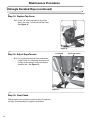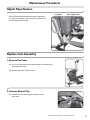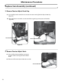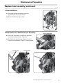
1
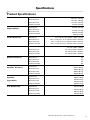
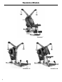
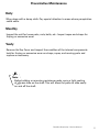
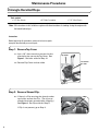
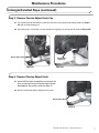
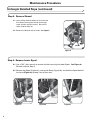
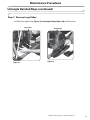
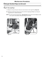
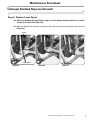
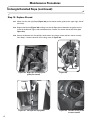
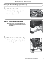
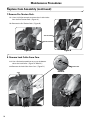
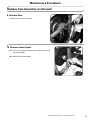
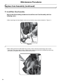
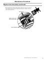
The Bowflex Revolution®,
Revolution®XP, and Revolution®FT
Home Gym
Service Manual
P/N: 000-6911 Rev A (04/2007)
Table of Contents
Specifications / Approvals................................ 3
Revolution Models............................................. 4
Preventative Maintenance................................ 5
Untangle Derailed Rope.................................... 6
Adjust Rope Tension........................................ 15
Replace Cam Assembly................................... 15
Replace Rope................................................... 22
Specifications
Product Specifications
Product Weight
Shipping Weight
Revolution®
234.3 lbs. (106.1kg)
Revolution® XP
XP with Lat Tower
291.2 lbs. (131.4kg)
319.9 lbs. (144.4kg)
Revolution®
414.46 lbs (188.1kg)
Revolution® FT
253.9 lbs. (115.1kg)
Revolution® XP
316.6 lbs. (143.5kg)
XP with Lat Tower
Product Dimensions
Revolution®
Number of Exercises
SpiralFlex® Resistance
SpiralFlex®
Upgradability
User Weight Limit
350.8 lbs. (159kg)
112”L x 63” W x 73”H (284cm x 160cm x 185cm)
Revolution® FT
64.5” L x 37.8” W x 73” H (163.8cm x 98cm x 185.4cm)
Revolution® XP
64.5” L x 37.8” W x 73” H (163.8cm x 98cm x 185.4cm)
XP with Lat Tower
Workout Area
336.2 lbs. (152.5 kg)
Revolution® FT
Revolution®
64.5” L x 37.8” W x 83.2” H (163.8cm x 98cm x 211.3cm)
112” x 63” (284cm x 160cm)
Revolution® FT
84” x 64” (213.4cm x 162.6cm)
Revolution® XP
84” x 64” (213.4cm x 162.6cm)
XP with Lat Tower
84” x 64” (213.4cm x 162.6cm)
Revolution®
90+
Revolution® FT
80+
Revolution® XP
90+
XP with Lat Tower
90+
Revolution®
220 lbs (99.8 kg)
Revolution® FT
200 lbs (90.7 kg)
Revolution® XP
200 lbs (90.7 kg)
XP with Lat Tower
200 lbs (90.7 kg)
Revolution®
300 lbs. (136 kg)
Revolution® FT
280 lbs (127 kg)
Revolution® XP
280 lbs (127 kg)
XP with Lat Tower
280 lbs (127 kg)
Revolution®
300 lbs (136 kg)
Revolution® FT
300 lbs (136 kg)
Revolution® XP
300 lbs (136 kg)
XP with Lat Tower
300 lbs (136 kg)
Bowflex Revolution™ Service Manual
Revolution Models
Revolution®
Revolution® FT
Revolution® XP
Preventative Maintenance
Daily
Wipe down with a damp cloth. Pay special attention to areas where perspiration
could settle.
Monthly
Inspect the unit for loose parts, nuts, bolts, etc.. Inspect ropes and straps for
fraying or excessive wear.
Yearly
Remove the Top Cover and inspect the condition of the internal components.
look for fraying or excessive wear on straps, ropes, and moving parts and
replace as necessary.
Note:
Before adding or removing resistance packs, spray a light coating
of silicone lube on the shaft. This will allow the packs to slide easily
on and off the shaft.
Bowflex Revolution™ Service Manual
Maintenance Procedures
Untangle Derailed Rope
Tools needed:
• 1/8” Allen Wrench
• 6” Phillips Screwdriver
• 7/32” Allen Wrench
Note: A
ll instructions in this bulletin are given with the orientation of standing facing the engine with
the bench behind you.
Instructions:
Before beginning this procedure, remove all resistance packs
except for the attached pre-stretch pack.
Step 1: Remove Top Cover
1-1 U
se a 1/8” allen wrench to remove the four
1-2 R
emove Top Cover and set aside.
allen bolts that secure the Top Cover. See
Figure 1. Set bolts aside for Step 14.
Top Cover
Pre-stretch
Pack
Figure 1
Step 2: Remove Shroud Clip.
2-1 If there is a Clip securing the shrouds under
Clip
top inside, remove the Clip. (The clip may
already have been removed after shipping.)
See Figure 2. Set Clip aside for Step 11.
If Clip is not present, go to Step 3.
Figure 2
Maintenance Procedures
Untangle Derailed Rope (continued)
Step 3: R
emove Tension Adjust Knob Cap
3-1 U
se a phillips head screwdriver to remove the screw securing Tension Adjust Knob Cap (Figure
3a) and set aside for Step 13.
3-2 O
nce the Screw is removed, use the screwdiver to gently pry the cap out of the knob (Figure 3b).
Tension Adust Knob
Tension Adust
Knob Cap
Figure 3a
Figure 3b
Step 4: R
emove Tension Adjust Knob.
4-1 Use a phillips head screwdriver to remove the
four screws securing the Tension Adust Knob.
See Figure 4. Set screws aside for Step 12.
4-2 Remove the Tension Adjust Knob and set aside.
Tension Adust Knob
Figure 4
Bowflex Revolution™ Service Manual
Maintenance Procedures
Untangle Derailed Rope (continued)
Step 5: Remove Shroud
5-1 U
se a phillips head screwdriver to remove the
five screws securing the shroud (one longer
screw and four shorter screws). Set screws
safely aside for Step 10.
5-2 R
emove the Shroud and set aside. See Figure 5.
Shroud
Figure 5
Step 6: Remove Lower Spool
6-1 U
se a 7/32” allen wrench to remove the bolt securing the Lower Spool. See Figure 6a.
Set bolt aside for Step 9.
6-2 R
emove the Spool (Figure 6a), unwrap the Strap (Figure 6b), and hook the Spool behind
the frame (Figure 6c) to keep it out of your way.
Lower Spool
Figure 6a
Figure 6b
Figure 6c
Maintenance Procedures
Untangle Derailed Rope (continued)
Step 7: Remove Large Pulley.
7-1 S
lide the Large Pulley (Figure 7a) and tangled Rope (Figure 7b) off of the axle.
Large Pulley
Figure 7a
Tangled Rope
Figure 7b
Bowflex Revolution™ Service Manual
Maintenance Procedures
Untangle Derailed Rope (continued)
Step 8: R
e-wrap Rope
8-1 B
egin to re-wrap the rope in the outer most channel on the Large Pulley (Figure 8a).
8-2 S
lide the Large Pulley back onto the axle and finish wrapping the Rope by turning the
Large Pulley in a clockwise direction.
NOTE: D
o not let go of the Large Pulley. (See Figure 8b.) Keep tension on the Rope to make
sure it stays in the channel while performing the next step.
Large Pulley
Figure 8a
10
Hold Pulley in place
Figure 8b
Maintenance Procedures
Untangle Derailed Rope (continued)
Step 9: Replace Lower Spool.
9-1 W
hile still holding the Large Pulley in place, coil the Strap around the Spool in a counter
clockwise dirction. (See Figure 9a).
9-2 Slide the Spool back onto the axle (Figure 9b) and secure the Lower Spool with allen bolt
(Figure 9c).
Strap
Lower Spool
Figure 9a
Figure 9b
Figure 9c
Bowflex Revolution™ Service Manual
11
Maintenance Procedures
Untangle Derailed Rope (continued)
Step 10: R
eplace Shroud.
10-1 Make sure that the right Rope (Figure 10a) passes above the flat guide to the upper right side of
the Pulley.
10-2 R
eplace the Shroud (Figure 10b) making sure the left Rope passes between the guides on the
inside of the Shroud (Figure 10c) and beneath the “fender” on the left side of the Pulley (see
Figure 10a).
10-3 S
ecure the Shroud with five phillips head screws (one longer screw and four shorter screws)
from Step 5. Note the location for the long screw in Figure 10d.
Right Rope
Right Guide
Strap
Left Shroud
Fender
Figure 10a - Right rope and rope guide
(pulley not shown)
Left Rope
Guides
Figure 10c - Left rope and rope guides
12
Figure 10b
Figure 10d - Location of long screw
to secure shroud
Maintenance Procedures
Untangle Derailed Rope (continued)
Step 11: R
eplace Shroud Clip
Clip
11-1 Replace
the Clip securing the shrouds
under top inside. See Figure 11.
If there is no Clip, go to Step 12.
Figure 11
Step 12: Replace Tension Adjust Knob
12-1 U
se a phillips head screwdriver and four
screws to secure the Tension Adjust Knob.
See Figure 12.
Figure 12
Step 13: R
eplace Tension Adjust Knob Cap
13-1 Use a phillips head screwdriver and one
screw to secure the Tension Adjust Knob
Cap. See Figure 13.
Figure 13
Bowflex Revolution™ Service Manual
13
Maintenance Procedures
Untangle Derailed Rope (continued)
Step 14: Replace Top Cover
14-1 U
se a 1/8” allen wrench and four allen
bolts rom step 1 to secure the Top Cover.
See Figure 14.
Figure 14
Step 15: Adjust Rope Tension
Large Pulley
15-1 Pull
out Tension Adjust Knob and rotate
Large Pulley in a clockwise direction until
it stops, then release the Tension Adjust
Knob to lock. See Figure 15.
Figure 15
Step 16: Final Check
lease inspect your machine to ensure that all fasteners
P
are tight and everything is properly assembled.
14
Tension Adjust Knob
Maintenance Procedures
Adjust Rope Tension
Large Pulley
Tension Adjust Knob
Pull out Tension Adjust Knob and rotate Large Pulley
in a clockwise direction until it stops then release the
Tension Adjust Knob to lock.
Replace Cam Assembly
1. Remove Top Cover.
1-1. Use a 1/8” allen wrench to remove the four allen bolts that
secure the Top Cover.
1-2. Remove Top Cover and set aside.
2. Remove Shroud Clip.
2-1. Remove the Clip securing the shrounds under
top inside.
Bowflex Revolution™ Service Manual
15
Maintenance Procedures
Replace Cam Assembly (continued)
3. Remove Tension Adjust Knob Cap.
3-1. Use a phillips head screwdriver to remove the screw securing Tension Adjust Knob Cap.
(Figure A)
3-2. Once the Screw is removed, use the screwdiver to gently pry the cap out of the knob.
(Figure B)
Tension Adust Knob
Tension Adust Knob Cap
Figure B
Figure A
4. Remove Tension Adjust Knob.
4-1. Use a phillips head screwdriver to remove
the four screws securing the Tension Adust
Knob.
4-2. Remove the Tension Adjust Knob and set aside.
Tension Adust Knob
16
Maintenance Procedures
Replace Cam Assembly (continued)
5. Remove Shroud.
5-1. Use a phillips head screwdriver to remove
the five screws securing the shroud
5-2. Remove the Shroud and set aside.
Shroud
6. Remove Tension Shaft From Cam Assembly.
Tension Shaft Holder
6-1. Use a 7/32”allen wrench to loosen the eight bolts
on the Tension Shaft Holder. ( Figure A)
6-2. Pull the Tension Shaft through ( Figure B ) until it
clears the Cam Assembly ( Figure C ) being replaced.
Figure A
Tension Shaft
Figure B
Cam Assembly
Figure C
Bowflex Revolution™ Service Manual
17
Maintenance Procedures
Replace Cam Assembly (continued)
7. Remove Pre-Tension Pack.
7-1. Use a 3/32”allen wrench to remove the six allen bolts
from the Pre-Tension Pack. ( Figure A )
7-2. Remove the Pre-Tension Pack. ( Figure B )
Cam Assembly
Pre-Tension Pack
Figure B
Figure A
8. Remove Lock Collar From Cam.
8-1. Use a flat head screwdriver to pry up the bottom
tab on the Lock Collar. ( Figure A / Detail A )
8-2. Remove the Lock Collar from Cam. ( Figure B )
Detail A
Cam
Figure A
18
Lock Collar
Figure B
Maintenance Procedures
Replace Cam Assembly (continued)
9. Remove Cam.
9-1. Remove Cam from Cam Axle.
10. Remove Lower Spool.
10-1. Use a 7/32” allen wrench to remove the bolt securing
the Lower Spool.
10-2. Remove the Lower Spool.
Bowflex Revolution™ Service Manual
19
Maintenance Procedures
Replace Cam Assembly (continued)
11. Install New Cam Assembly.
Reverse the disassembly procedure to install the new Cam Assembly with the
following notes.
1.When replacing the Lower Spool, make sure to wind the strap counter clockwise. ( Figure A )
Lower Spool
Figure A
2.When sliding the Tension Shaft back into position, slowly slide the shaft through until it clicks
into place. If you do not feel or hear a distinct click, make sure the shaft is centered by measuring
the amount of exposed shaft on each side of the main unit.
20
Maintenance Procedures
Replace Cam Assembly (continued)
2.When tightening the Tension Shaft Holder, tighten the screws in numerical
order shown on the tensioner. Tighten the two screws marked 1 then the
two marked 2 and so on.
Tension Screws
Tighten screws in order
1&1, 2&2, 3&3, then 4&4.
Tension Shaft Holder
Bowflex Revolution™ Service Manual
21
Maintenance Procedures
Replace Rope
1. Follow Steps 1-5 of Replace Cam Assembly to Remove Shroud.
2. Remove Lower Spool
2-1. Use a 7/32” allen wrench to remove the bolt securing the Lower Spool.
2-2. Remove the Spool,(Figure A) unwrap the Strap (Figure B) and hook the Spool behind the frame
(Figure C) to keep it out of your way.
Lower Spool
Figure A
Figure B
Figure C
3. Remove Large Pulley.
3-1. Slide the Large Pulley off of the axle.
22
Large Pulley
Maintenance Procedures
Replace Rope (continued)
4. Remove Rope From Pulley.
9-1. Remove Cam from Cam Axle.
5. Remove Old Rope.
Upper Pulley
5-1. Raise the Arm to fully upright position.
Rope
5-2. Tie a piece of string (about 6 feet long) to the end
of the old Rope. ( Figure A )
Arm
5-3. Gently pull the old Rope through the Arm and and
over the Upper Pulley leaving the string theaded
through the arm. ( Figure B )
Note: Do not pull the string through the arm. Leave enough
string exiting at the Lower Pulley to pull the new Rope
back through.
Rope
String
Lower Pulley
Figure A
Figure B
Bowflex Revolution™ Service Manual
23
Maintenance Procedures
Replace Rope (continued)
Lower Pulley
6. Route New Rope.
6-1. Untie the old Rope from the string at the Upper Pulley and
tie the string to the new Rope.
6-2. Thread the new Rope through the Arm by gently pulling
the string from the Lower Pulley.
Rope
String
7. Clamp Rope In Large Pulley.
7-1. Feed the Rope through the hole in the Large Pulley and
clamp in place.
Note: To be sure Rope is securely clamped, leave about 1/4”
showing on the inside of the clamp.
1/4” of Rope showing
8. Reverse Steps 3,2, and 1 to reassemble..
24
©2005 Nautilus Inc. All rights reserved. 16400 S.E. Nautilus Drive, Vancouver, Washington, USA 98683.
Bowflex, Bowflex Revolution, Spiraflex, and the Bowflex and Nautilus logos are either registered trademarks or trademarks of Nautilus, Inc.
Bowflex Revolution™ Service Manual
25