Transcript
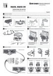
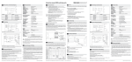
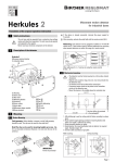
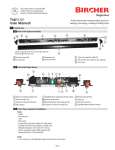
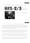
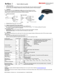
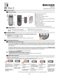
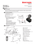
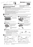
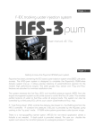
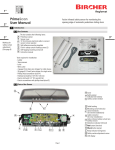
Instruction manual ESD3 switching units
Blockschema und Anschlussbelegung
6
9
Gehäuse
Schutzart
Schutzart Einsatzort
Gewicht
Spannungsversorgung
nach EN60204-1
(typenabhängig)
Frequenzbereich
Leistungsaufnahme
Einschaltdauer
Befestigung
12
Signalgeber 1
1
2
Signalgeber 2
3
4
13
15
5
6
*
16
7
8
9
10
Klemme
1
2
3
4
5
6
7
8
Klemme
9
10
11
12
13
14
15
16
Signalgeber 1
Signalgeber 1
Signalgeber 2
Signalgeber 2
externer Reset
externer Reset
Melderelais
Melderelais
Sicherheitsausgangs-Relais
Gebrauchskategorie
nach EN60947-4-1**
Speise-Spannung
Speise-Spannung
–
Sicherheitsausgang 1
Sicherheitsausgang 1
–
Sicherheitsausgang 2
Sicherheitsausgang 2
Gebrauchskategorie
nach EN60947-5-1**
(DC13: 6 Schaltspiele/Min.)
Kontaktabsicherung
nach EN60947-5-1
Kontakte
Lebensdauer
*Bei Versionen mit automatischem Reset ist dieser in der Schaltung integriert
Beschaltung
7
P
12
1
2
Signalgeber 1
Signalgeber 2
*
Melderelais
Schaltvermögen**
13
15
3
4
16
5
6
Anzeigen
Betrieb
Störung
Sicherheitsabschaltung
7
8
9
Technische Daten
M
10
1
DIN ABS, rot/schwarz
IP30 (IEC 529)
IP54
max. 250 g (typenabhängig)
24 VACDC ±10%
115 VAC ±10%
230 VAC ±10%
50/60 Hz (45–66 Hz)
max. 5 VA
100% ED
Hutschiene 35 mm nach EN 50022
AC-1: 250V/2A/500VA
ca. 300’000 Schaltspiele
DC-1: 24V/2A/48W
ca. 700’000 Schaltspiele
AC-15: 250V/2A/500VA
ca. 130’000 Schaltspiele
DC-13: 24V/2A/48W
ca. 70’000 Schaltspiele
2 A träge
2.2
Safety Instructions
• The assembly, commissioning, modifications and extensions may only be
completed by an experienced electrician!
• Before commencing work remove the power supply from the units/installations!
• During the operation of electrical components
– components are connected with dangerous voltages
– e. g. in the case of a short circuit hot and ionised gases can be emmited
– protection covers are not to be removed!
• Pay attention to all local relevant electrical safety regulations!
• Disregard of the safety regulations can cause death, severe injuries or
extensive damage!
• Keep the these operating instructions in a safe place for later use!
Before commencing the installation or assembly complete the following safety precautions:
• Check the voltage data on the type plate of the switching unit.
• Remove the power supply from the units/installation!
• Ensure that the units/installations can not be switched on!
• Determine that the power supply is disconnected!
• Ground the phases and short circuit!
• Separate or cover neighbouring components which are connected to the
power supply!
• Cover the unit during assembly!
Foreign particles (e.g. borings from drilling) can the damage the unit.
• Protect the unit with a housing against contamination or aggressive
environments!
Limited protection against accidental contact!
zwangsgeführte Relais, AgCuNi
mech. 50 Mio. Schaltspiele
2
Product Description
ESD3 switching units are used for monitoring pressure sensitive protective devices from
Bircher Reglomat AG (for contact mats acc. to EN 1760-1, for safety edges acc. to EN 1760-2).
They meet the requirements of standard EN 954-1 for protective equipment up to safety
category 3, if the drive is directly connected to the ESD3.
24VDC/1A, resistive Last
30VAC/1 A, resistive Last
grün
rot (Signalgeber-/Systemstörung)
gelb (Signalgeber)
The ESD3 is fail-safe (single fault) and has two input channels with redundant evaluation.
Each channel controls a positively driven relay. During each switching operation, the relays
test themselves by means of contact feedback.
N
Ansprechzeit
Sicherheitsausgangs-Relais
Anschlussbeispiel für einphasigen Antrieb ohne Hilfsschütz
45
< 50 ms
F2–4
1
2
Signalgeber 1
Signalgeber 2
13
15
3
4
*
5
6
9
Maschinensteuerung
16
7
1)
Funzione
ión
Func
Für die 24 VACDC-Speisung muss die Versorgung aus einem Sicherheitstrafo nach
IEC 742 erzeugt werden. Die Leitungsverlegung muss geschützt vor mechanischen
Beschädigungen erfolgen.
When one or more sensors are activated
• the total resistance of the activated sensor system sinks towards zero ohm
• the value falls below the defined threshold
• the “safety” relay is de-energised
• the yellow LED’s illuminate
3
yd
Sk tiv
ak
el
arf
Giv
1)
10
K2
Weitere Angaben zum Einsatz eines ESD3-Schaltgerätes mit Schaltmatten oder -leisten als
Sicherheitssystem entnehmen Sie bitte aus der Benutzerinformation (auf Anfrage bei einer
unserer Vertriebsstellen erhältlich).
M
3
N
Anschlussbeispiel für dreiphasigen Antrieb mit Hilfsschützen
1) K1 und K2 müssen so ausgelegt sein, dass das Verschweissen der Kontakte sicher durch K1
und K2 erkannt wird und nicht zum Verlust der Sicherheit führt
Wartung und Fehlersuche
Nach korrekter Montage und Installation und bei Beachtung der technischen Daten arbeitet
das Gerät wartungsfrei. Die korrekte Funktion des Sicherheitssystems muss jedoch periodisch
(monatlich, oder nach übergeordneten Vorschriften) geprüft werden. Dabei sind auch die
Signalgeber und Zuleitungen auf mechanische Beschädigungen zu kontrollieren.
Ist die Funktionalität nach Verdrahtung gemäss Schaltplan nicht gewährleistet und leuchten
beide gelben bzw. roten LEDs, gehen Sie folgendermassen vor:
1. Reset-Taste drücken (min. 1 Sek.)
2. Sämtliche Signalgeber auf Betätigung oder Beschädigung überprüfen
3. Signalgeber-Widerstände an Klemmen 1/2 und 3/4 prüfen (8.2 kOhm)
4. Erneute Inbetriebnahme
Leuchten danach immer noch beide roten LEDs, so liegt eine Gerätestörung vor. Gerät
zurück zur Kontrolle.
Leuchtet nur eine gelbe bzw. rote LED Gerät zurück zur Kontrolle.
10 Gewährleistung und Haftung
1. Die Gewährleistung und Haftung der Bircher Reglomat AG richten sich nach dem Kaufvertrag.
2. Die Gewährleistung und Haftung erlischt vorzeitig, wenn der Kunde oder Dritte das Produkt
nicht gemäss der vorliegenden Betriebsanleitung einsetzen und/oder bedienen, der Kunde
oder Dritte unsachgemässe Änderungen oder Reparaturen vornehmen, der Kunde oder
Dritte, falls ein Mangel aufgetreten ist, nicht umgehend alle geeigneten Massnahmen zur
Schadensminderung treffen und der Bircher Reglomat AG Gelegenheit geben, den Mangel
zu beheben.
3. Von der Gewährleistung und Haftung ausgeschlossen sind Schäden, die nicht nachweisbar
infolge schlechten Materials, fehlerhafter Konstruktion oder mangelhafter Ausführung
entstanden sind sowie Schäden, die aus anderen Gründen entstanden sind, welche die
Bircher Reglomat AG nicht zu vertreten hat.
4. Eine Haftung für Folgeschäden ist ausgeschlossen, soweit zwingende produktehaftpflichtrechtliche Bestimmungen dem nicht entgegenstehen.
5. Die Gewährleistungsansprüche aus dem Kaufvertrag gegenüber dem Händler werden
durch diese Bestimmungen nicht berührt.
6. Bircher Reglomat AG entwickelt ihre Produkte zum Nutzen ihrer Kunden stetig weiter.
Bircher Reglomat AG behält sich das Recht vor, ohne vorherige Ankündigung, an jedem in
dieser Dokumentation erwähnten Produkt, Änderungen vorzunehmen.
Bircher Reglomat AG, Wiesengasse 20, CH-8222 Beringen, Tel. +41(0)52 687 11 11, Fax +41(0)52 687 11 12
Änderungen vorbehallten
Sensor 2
3
4
13
15
5
6
16
7
8
Terminal
1
2
3
4
5
6
7
8
Terminal
9
10
11
12
13
14
15
16
Signal Sensor 1
Signal Sensor 1
Signal Sensor 2
Signal Sensor 2
External Reset
External Reset
Status Relay
Status Relay
Supply Voltage
Supply Voltage
–
Safety Output Relay 1
Safety Output Relay 1
–
Safety Output Relay 2
Safety Output Relay 2
Safety Output Relay
Utilization category
acc.to EN60947-4-1**
Utilization category
acc.to EN60947-5-1**
(DC13: 6 switchings/
minute)
Contacts
Operating Life
Fuse Protection
acc. to EN60947-5-1
*Versions with automatic reset have this function integrated in the circuit
Commissioning
• It is recommended that the resistance of the sensor is measured on the terminals 1 and 2
as well as 3 and 4. This should be between 7.5 and 9.0 kOhm with a non-activated sensor
(typical 8.2 kOhm)
• Check that the power supply is in accordance with the value indicated on the type plate of
the unit
• If one or more sensors are activated both yellow LED’s “Safety Function” illuminate and
both signal output relay de-enegise. The sensors must now be activated at various positions whereby both yellow LED’s must illuminate each time. The signal output relays remain
de-energised
• Push the external reset button (ESD3-05/05C/06/09), minimum 1 second.
• If a terminal of the sensor input (e.g. 1) opened and the sensor connection is disconnected
the sensor output relays will de-energise and the red LED’s “System Error” illuminate. The
fault indicator contact opens (respectively closes with ESD3...C)
• If the terminal is subsequently closed the fault condition remains until the external reset
button is pressed (ESD3-05/05C/06/09), or the power supply is disconnected for a few seconds
Control of External Contactors
7
P
12
Sensor 1
1
2
Sensor 2
3
4
*
Status Relay
Switching Capacity**
13
15
16
5
6
7
8
9
M
10
4
DIN ABS, red/black
IP30 (IEC 529)
IP54
max. 250 gramm (depending on type)
24 VACDC ±10%
115 VAC ±10%
230 VAC ±10%
50/60 Hz (45–66 Hz)
max. 5 VA
100%
35 mm mounting rail acc. to EN 50022
AC-1: 250 V/2 A/500 VA
approx. 300’000 switchings
DC-1: 24 V/2 A/48 W
approx. 700’000 switchings
AC-15: 250 V/2 A/500 VA
approx. 130’000 switchings
DC-13: 24 V/2 A/48 W
approx. 70’000 switchings
positively driven relays, AgCuNi
mechanical 50 million switchings
2 A slow
24VDC/1A, resistive load
30VAC/1 A, resistive load
Indicators
Operation
Error
Safety Switch-off
Green
Red (sensor resp. system error)
Yellow (sensor)
Reaction Time
Safety Output Relay
< 50 ms
Temperature Range
Operation
Storage
Humidity
–20°C to +55°C
–20°C to +80°C
max. 80% relative (no condensation allowed)
N
Wiring example for a one phase drive without control relay
F1
Assembly and Removal
L1
L2
L3
12
A
E
1
Sensor 1
1
2
Sensor 2
3
4
Serv
ice
Po
we
Commutazione
Arrê
r
di sicurezza sé
t de
S
curité
ia
Stoafety
p
AnomaliaDDé
3
raESD3
S
ng Se
l periferica
3 E détecteuEem
en
n
de
t
rrro sor
Fallo or SD
r
ESD
sens E
3
2
senc
re
k
ds
1
2
Technical data
Housing
Isolation Class
Protection Class
Weight
Power Supply
acc. to EN60204-1
(depending on type)
Frequency Range
Power consumption
Duty Cycle
Fastening
9
10
The switching unit is reset as follows
• by pressing an external reset button (ESD3-05/05C/06/09) external reset,
• as soon as the sensor is no longer actuated (ESD3-03/03C/04/08) auto reset,
• when the electrical power supply is interrupted.
The recovery time is < 1 sec., then the green LED lights up.
Pre
ts
ft
Dri
Sensor 1
*
When an Error occurs in the sensor circuit (cable breakage, sensor malfunction)
• the total resistance of the corresponding sensor system rises
• the defined switching limit is exceeded
• the “safety” relay is de-energised
• the red and yellow LED’s illuminate
*
3
ES
D
3
8
K1
8
105
9
12
The switching unit is designed to be installed on a horizontally mounted mounting rail.
Stick-on labels in the
following languages:
en, fr, it, es, sv
79
12
Temperaturbereiche
Betrieb
–20°C bis +55°C
Lagerung
–20°C bis +80°C
Luftfeuchtigkeit
max. 80% relativ (keine Betauung zulässig)
**Nicht aufgeführte Bemessungsdaten erfragen Sie vom Werk
Block Diagram and Connection
6
Connected sensors have a terminal resistance of 8.2 kOhm and are monitored for changes in
the continously flowing no-load current. In the non-activated condition all relays are energised.
Plug-in terminals with
cage clamps
F1
L1
L2
L3
Function
4
F2–4
13
15
5
6
9
Machine
control
**If not mentioned ratings are required, ask for them at the manufacturer
For 24 VACDC supply voltage must be obtained from a safety trafo according to
IEC742. The wiring must be protected against mechanical damage.
16
7
1)
8
For further information on using an ESD3 switching unit as a safety system with contact mats
or edges, please request the relevant information from one of our sales offices.
K1
2.1
Configuration variants
Type
ESD3-03
ESD3-04
ESD3-05
ESD3-06
ESD3-08
ESD3-09
ESD3-03C
ESD3-05C
Status
relay
contact
closed
when:
auto external
X
X
Signalling contact
M
Status relay
Fault contact Fault contact
SM
C
X
Signalling contact
D
X
X
X
X
X
X
X
X
X
X
Sensor not
actuated
Sensor not
actuated
Sensor
actuated
Fault
De-energised
D
Assembly
A) Place the unit (1) at a slight angle with the guides (2) on the rail (3)
(Rail 35 mm according to EN 50022)
B) Push the unit (1) onto the rail (3) until the lock (4)
Removal
C) Place a screwdiver (5) on the red lock
D) Unlock the unit by turning or levering the screwdriver
E) Lift the unit and remove from the rail
5
Sensor
actuated
Fault
De-energised
M
3
C
5
X
X
X
10 Warranty and Liability
K2
The ESD3 variants are distinguished firstly by their reset function and secondly by the configuration of the status relay contact. This can be implemented off-load both as open and
closed. It is not a safety contact, but is exclusively used for transmitting information. It is not
monitored for failure and must never be used for safety shutdown in any form whatsoever.
Each type is available in three voltage supply variants: 24 V AC/DC, 115 V AC, 230 V AC.
Reset
1)
10
B
•
•
•
•
•
8
Periodical Checks and Fault Finding
The correct functioning of the safety system must be checked periodically (monthly or according to overruling regulations). The sensor and wiring connections must also be checked for
mechanical damage.
Connection
The maximum length of the sensor with cable must not exceed 50 metres
Maximum surface area 5 m 2
If multiple sensors are used, they have to be connected in series
The last sensor equipped with resistor 8.2 kOhm
If only one sensor input is used channel 2 must be jumpered (provided resistance
8,2 kOhm ±1%), otherwise a fault signal is generated
Bircher Reglomat AG, CH-8222 Beringen, Switzerland, Phone +41 (0)52 687 11 11, Fax +41 (0)52 687 12 10
N
Wiring example of a three-phase drive with control relay
1) Note: the contactors K1 and K2 must be designed in a way that welding of the contacts is
recognized by K1 and K2 and does not lead into a loss of safety
Subject to change without notice
Proceed as follows if the function is not assured based on the wiring in the circuit diagram and
both yellow or red LEDs light up at the same time:
1. Press reset button (min. 1 sec.)
2. Check all sensors to determine if activated or damaged
3. Check sensor resistance on terminals 1/2 and 3/4 (8.2 kOhm)
4. Repeat commissioning
1. The warranty and liability of Bircher Reglomat AG are based on the sales contract.
2. The warranty and liability shall expire prematurely, should the client or third parties not
use and/or operate the product in compliance with existing operating instructions, should
incorrect changes or repairs be made by the client or third parties, should the client or
third parties, when a fault has occurred, not take suitable steps at once for a reduction of
possible damage/losses and offer Bircher Reglomat AG a chance for remedying the said
fault.
3. The warranty and liability shall exclude any damage for which there is no proof that it
is due to poor materials, faulty construction, poor workmanship, and any damage caused
by other reasons, for which Bircher Reglomat AG cannot be held liable.
4. No liability can be assumed for any consequential damage, provided this is not governed
otherwise by applicable product liability laws and regulations.
5. Warranty claims made against the seller on the basis of the sales agreement are not
affected by these regulations.
6. For the benefit of its customers Bircher Reglomat AG constantly develops its products
further. Bircher Reglomat AG reserves the right to make changes to any of the products
described in this document without prior notice.
There is a unit fault if both red LEDs continue to light up afterwards. Return the unit for
checking.
If only one yellow or red LED lights up Return the unit for checking.
Bircher Reglomat AG, CH-8222 Beringen, Switzerland, Phone +41 (0)52 687 11 11, Fax +41 (0)52 687 12 10
Subject to change without notice