1
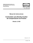
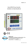
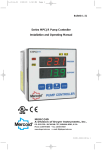
IN-526-N
8/30/05
2:06 PM
Page 1
Bulletin IN-526-N
Installation Instructions (Preliminary)
Series D-7000-(N) Remote Bulb Temperature Controls
ENCLOSURES – TYPE NO. PREFIX
WEATHER-RESISTANT
GENERAL PURPOSE
Prefixed by
Prefixed by
DAW, DLW, DRW, DSW
DA, DL, DR, DS
CONTROL NUMBERS
Part of the control number following Type No. Prefix identifies the style of the
control case.
The digit 5 of 7035 denotes a plain case with bottom connection.
The digit 8 of 7038 denotes a flanged case with bottom connection.
The digit 9 of 7039 denotes a flanged case with back connection.
CIRCUITS (SWITCH OPERATION)
Suffix number after control number denotes number of circuits and circuit
operation.
Suffix -153 designates SPDT - one circuit closes as other circuit opens.
Suffix - 804 designates 2 ea. SPDT switches - two circuits close as two circuits open.
LOCATION AND MOUNTING OF CONTROL CASE
Follow equipment manufacturer’s instructions or proceed as follows:
Vibration causes erratic operation of any instrument and shortens its life. It is
important to select a location that is reasonably free of vibration. All controls
must be mounted vertical and level. Delrin bushed movements prolong control life by alleviating excessive wear of metal surfaces due to vibration and/or
pulsation. It is identified by the letter “B” after the suffix number. Example: 2B, -3B, -804B, etc.
General Purpose Types - DA, DS, DL, DR - These controls without a
flange plate are mounted by means of a bracket supplied with the control. For
panel mounted use the holes provided on the flanged case. See drawing
1000F on page 4.
Weather Resistant Types - DAW, DSW, DRW, DLW - For surface mounting only. Has flanged case with bottom connection. See drawing 1062 on
page 4.
EXPLOSION PROOF
Prefixed by
DAH, DLH, DRH, DSH
EXPLOSION PROOF
Prefixed by
DAE, DLE, DRE, DSE
BULB PROTECTION
There are three ways to protect bulb No. 2:
1. Before tightening packing gland, pull bulb back into union as far as possible (standard No. 2 bulb with 3/4˝ union only). The union is recessed to provide some support.
2. Where insertion depth is greater than bulb length, use extension sleeve “B”.
See illustration Nos. 8, 9, and 10.
3. Separable Wells (see drawing No. 10): wells slow down heat transfer of
temperature changes to the bulb and consequently increase response time
of control the union will slide back on capillary allowing complete immersion
of bulb in any depth of well.
FOR DIMENSIONS OF BULBS, SEE CHART - PAGE 3
Caution: When installing bulbs with union connections, be careful not to twist
the flexible tubing. Loosen packing nut or union so that the union can turn
freely around tubing. After union is firmly secured to the pipe or tank, position
bulb by sliding tubing through union and then tighten the packing gland nut.
CROSS AMBIENT TEMPERATURE EFFECTS
There are no cross ambient effects associated with these gas actuated units
which are designed with a range number ending with “n”, i.e. -5N.
WHERE TURBULENT OR FAST
FLOWING LIQUIDS PREVAIL
Bulb supports for bulb No. 2 are used where the bulb is mounted in turbulent
or fast flowing liquids or where it is desired to insert the remote bulb at some
distance within a vessel, pipe, or tank. See “B” in illustration Nos. 8, 9 and 10.
The remote bulb should be positioned so that at least one inch of the bulb is
within the extension sleeve “B” (dimension “B”) in order to insure firm support.
No. 2 bulb union is threaded to receive extension sleeve “B”. Extension addition “A” permits extending the mounting through insulation.
Explosion-Proof Types - DAE, DSE, DLE, DRE, DLH, DAH, DSH, DRH Secure with the mounting lugs provided on the housing. See drawings 98D
and 1350 on page 4.
LOCATION OF REMOTE BULB
To Insure Proper Control Operation:
1. The temperature bulb should be completely immersed in the medium being
controlled.
2. BULB MUST BE CORRECTLY LOCATED AND PROPERLY INSTALLED so
that the temperature changes at the bulb reflect actual temperature changes
of the medium being controlled.
3. Be sure the bulb will not be affected by external temperatures.
4. Bulb may be installed vertically or horizontally. The following precautions
should be taken:
(a) Do not install bulb in dead end of pipe, tank, etc., where it would not be
subject to free circulation of the medium being controlled. See illustration No.
5.
(b) If bulb No. 2 is located in a pipe or duct with diameter larger than the bulb
length, the bulb can be installed perpendicular to the pipe if protected from
possible damage due to flow velocity.
(c) If bulb No. 2 is to be inserted into a pipe with a diameter smaller than the
bulb length (ex. a 2-7/8˝ long bulb in a 1˝ pipe) the bulb should be located longitudinaly in the pipe so that the entire length is exposed to the flowing medium (ex. replace an elbow in the pipe with a tee and install bulb as shown in
illustration No. 6 and 7. If pipe is 1˝ diameter or less, provide an enlarged section around the bulb so that it does not restrict flow.
(d) When bulb No. 2 is to be inserted in a rapidly flowing stream of fluid in a
pipe or duct, make sure that it is mechanicaly protected against the velocity
in order to prevent the bulb from breaking off at the capillary.
5. Gas activated bulbs, unlike vapor pressure bulbs, do not have any elevation effects. Therefore, no compensation is required.
MERCOID DIVISION
DWYER INSTRUMENTS, INC.
P.O. BOX 258 • MICHIGAN CITY, INDIANA 46361, U.S.A.
ILLUSTRATION
NO. 6
ILLUSTRATION NO. 5
INCORRECT
INSTALLATION
Note that a very small
portion of the bulb is
exposed to the direct
path of medium being
controlled. section
containing bulb has
no flow so its temperature is affected by
radiation to or from
the surrounding air.
ILLUSTRATION
NO. 7
RECOMMENDED
INSTALLATION
These two illustrations indicate the bulb is completely
exposed (in direct path) of medium being controlled.
ILLUSTRATION
NO. 8
Phone: 219/879-8000
Fax: 219/872-9057
ILLUSTRATION
NO. 9
www.dwyer-inst.com
e-mail: [email protected]
IN-526-N
8/30/05
2:06 PM
Page 2
WELLS
Wells (with dimensions “A” and “C” in illustration 10) are used to protect the remote
bulb from physical damage or to permit
removal of the bulb without draining the
system.
The use of a well will increase the time lag
of the control since the temperature
change of the controlled medium must be
transmitted through the wall of the well
and then the bulb. Thus when wells are
used, it is important that the well dimension “C” be greater than or equal to the
bulb length “B” to insure that all of the
temperature sensistive portion of the bulb
is within the liquid area.
TWO-STAGE TEMPERATURE CONTROL
SERIES D-7435
ILLUSTRATION
NO. 10
WIRING
Wire in accordance with local electrical codes or follow equipment manufacturer’s recommendations. On general purpose controls, do not attach
ridged conduit to case. use a short strip of BX to relieve conduit expansion
and contraction strains.
Where a control is connected directly into the load circuit, it must be connected into the hot side of line.
Do not overload electrically - see nameplate attached to control for electrical rating.
ADJUSTMENTS
How to Set Operating Point of Control
DOUBLE ADJUSTMENT TYPES –
FULLY AUTOMATIC
Prefixed by DA, DAE, DAH, DAW –
Provided with double adjustments. Adjust
the upper pointer to set the “high” temperature point for switch operation. Adjust
the lower pointer to set the “low” temperature operating point. The difference
between the upper and lower pointers is
the operating differential between “on-off”
switch operation. Minimum differential for
each range is shown on Page 3.
DA –
DS –
SINGLE ADJUSTMENT TYPES –
FULLY AUTOMATIC
Prefixed by DS, DSE, DSH, DSW –
Equipped with a single adjustment. The
single pointer on the scale sets the temperature where switch operation occurs.
Differential is fixed (not adjustable). For
fixed differential of each respective range,
see Page 3.
SEMI-AUTOMATIC CONTROL
WITH MANUAL RESET
DR-7035-153U. A single adjustment sets
the operating point for automatic operation. A push button reset must be operated manually to restore the circuit to the
original position after automatic operation.
Example – Type DR-7035-153L: circuit will
open automatically on a temperature rise
to the temperature indicated by the pointer
on the scale – no matter how much the temperature drops, the circuit will
not reclose until the reset button is operated.
Suffix -L denotes control will operate automatically on an increase.
Suffix -U denotes control will operate automatically on a decrease.
DR –
TYPES DA-7435, DAW-7438, DAH-7435, DAE-7435 – This series incorporates two single pole, double throw snap switches, actuated by the
same Bourdon Tube. The operating point of each switch is adjustable
through an outside knob. The change in temperature which opens and
closes each switch at its respective setting is the “fixed differential” (sensitivity) of the switch. The temperature represented by the difference
between the two adjustment points is the temperature “spread” between
operation of the two switches. Upper pointer indicates the operating point
of the “high” temperature circuit. Lower pointer indicates the operating
point of the “low” temperature circuit.
OPERATING RANGES/SERIES D-7435
With Snap-Action Contacts
Range
No.
1N
3N
4N
5N
7N
8N
9N
10N
11N
Scale Range
-60 to 30°F (-50 to 0°C)
0 to 100°F (-18 to 40°C)
50 to 150°F (10 to 65°C)
100 to 200°F (40 to 95°C)
140 to 300°F (60 to 150°C)
250 to 415°F (120 to 215°C)
350 to 550°F (175 to 290°C)
100 to 300°F (40 to 150°C)
100 to 500°F (40 to 260°C)
Fixed Deadband
Max. Temperature Min. Spread
Not To Exceed Between Switches Each Switch
4°F (2°C)
12°F (7°C)
150°F (65°C)
4°F (2.5°C)
13°F (8°C)
240°F (115°C)
4°F (2.5°C)
13°F (8°C)
250°F (120°C)
4°F (2.5°C)
12°F (7°C)
300°F (150°C)
6.5°F (4°C)
18°F (10°C)
500°F (260°C)
7°F (4°C)
18°F (10°C)
550°F (290°C)
8°F (4.5°C)
22°F (13°C)
600°F (315°C)
8°F (4.5°C)
22°F (13°C)
500°F (260°C)
16°F (9°C)
46°F (26°C)
600°F (315°C)
ELECTRICAL RATING
AC capacities: 5A @ 120 V, 5A @ 240 V. (Not available for 440 V).
DC capacity: 5A, 30 V resistive.
IN-526-N
8/30/05
2:06 PM
Page 3
OPERATING RANGES/SERIES D-7000
With Snap-Action Contacts Types: DA-7035, DA-7235-153 & DA-7235-804
Adjustable Deadband Adjustable Deadband Fixed Deadband
DS-7235-804
DS-7035-153
DS-7235-153
(2) SPDT
Adjustable
Max. Process
Operating
Range Temp. Not To
Minimum
Fixed
Fixed
Range
No.
Exceed
Deadband
Deadband
Deadband
-60 to 30°F (-50 to 0°C)
1N
150°F (65°C)
23°F (13°C)
5°F (3°C)
5°F (3°C)
0 to 100°F (-18 to 40°C)
3N
240°F (115°C)
25°F (14°C)
5°F (3°C)
5°F (3°C)
50 to 150°F (10 to 65°C)
4N
250°F (120°C)
25°F (14°C)
5°F (3°C)
5°F (3°C)
100 to 200°F (40 to 95°C)
5N
300°F (150°C)
25°F (14°C)
5°F (3°C)
5°F (3°C)
140 to 300°F (60 to 150°C)
7N
500°F (260°C)
41°F (23°C)
8°F (4.5°C)
8°F (4.5°C)
250 to 415°F (120 to 215°C)
8N
550°F (290°C)
42°F (23°C)
9°F (5°C)
9°F (5°C)
350 to 550°F (175 to 290°C)
9N
600°F (315°C)
50°F (28°C)
10°F (6°C)
10°F (6°C)
100 to 300°F (40 to 150°C)
10N
500°F (260°C)
50°F (28°C)
10°F (6°C)
10°F (6°C)
100 to 500°F (40 to 260°C)
11N
600°F (315°C)
100°F (56°C)
20°F (12°C)
20°F (12°C)
ELECTRICAL RATINGS
See Code D
See Code E
See Code G
(1) All bulbs, including those with a copper capillary, are made or Type 304 Stainless Steel
(2) Insertion depth may be increased through use of bulb supports or wells.
Circuit
Suffix No.
-153
-804
Switch Action
SPDT one circuit OPENS as other CLOSES
Two SPDT operate simultaneously in one direction upon increase
(or decrease when specified)
Bulb Furnished With 6˝
Capillary Unless
Otherwise Specified (1)
Bulb No./Cap. Mat’l.
No. 2 SS/Copper
No. 2 SS/Copper
No. 2 SS/Copper
No. 2 SS/Copper
No. 2 SS/Copper
No. 2 SS/SS
No. 2 SS/SS
No. 2 SS/Copper
No. 2 SS/SS
Bulb Min.
Insertion
Depth (2)
2-7/8˝ (73 mm)
2-7/8˝ (73 mm)
2-7/8˝ (73 mm)
2-7/8˝ (73 mm)
2-7/8˝ (73 mm)
2-7/8˝ (73 mm)
4-7/8˝ (124 mm)
2-7/8˝ (73 mm)
2-7/8˝ (73 mm)
Repeatability: ±1% of full scale.
AC Capacity
Circuit
Code Suffix No. 120V
D
-153
15A
E
-153
15A
G
-804
5A
240V
440V
15A 15@480V
15A
NA
5A
NA
DC Resistive
120V
1/2A
240V
1/4A
Horsepower
AC
1/8
NA
DC
NA
NA
NA
1/4 HP at 120V AC, 1/2 HP at 240V AC.
DC rated controls (up to 10A), consult factory.
5A, 30V DC resistive.
GENERAL BULB INFORMATION
All bulbs are made of 304 stainless steel; capillary material is either copper or 316 stainless steel, as shown in the range table. The maximum pressure of bulbs
with a process connection is 300 psi. Other bulbs are for non-pressurized (e.g., open tank) use only. Consult the factory for higher pressure applications.
RANGE TABLE – NO. 2 BULB
Standard 11/16˝ Diameter Series D Bulb & 3/4˝ NPT Connection
Optional 11/16˝ Bulb & 1/2˝ NPT Connection
Range Numbers
Range Numbers
Bulb (1)/
6 ft. Cap. 1N, 3N, 4N,
1N, 3N, 4N,
Tubing
9N
9N
5N, 7N, 10N
8N, 11N
8N, 11N
5N, 7N, 10N
SS Bulb/
Copper
Capillary
E=2-7/8˝
B=2-7/8˝
Standard
N.A.
N.A.
SS Bulb/
SS Cap.
E=2-7/8˝
B=2-7/8˝
Option
E=2-7/8˝
B=2-7/8˝
Standard
E=4-7/8˝
B=4-7/8˝
Standard
Optional
11/16˝ Bulb
with
1/2˝ NPT
Process
Conn.
E=3-1/2˝
B=2-7/8˝
N.A.
N.A.
E=3-1/2˝
B=2-7/8˝
E=3-1/2˝
B=2-7/8˝
E=5-1/2˝
B=4-7/8˝
RANGE TABLE – NO. 2 BULB
Optional 1/2˝ Bulb & 3/8˝ Bulbs with 1/2˝ NPT Connection
Optional 1/2˝ & 3/8˝ Diameter Bulbs with 3/4˝ NPT Connection
Range
Numbers
Range Numbers
Bulb (1)/
6 ft. Cap. 1N, 3N, 4N,
8N, 11N
9N
1N, 3N, 4N,
8N, 11N
9N
Tubing
5N, 7N, 10N
5N, 7N, 10N
E=5-3/4˝
N.A.
N.A.
E=6-3/8˝
N.A.
N.A.
SS Bulb/
Optional
Optional 1/2˝ Diameter Bulb
B=5-3/4˝
B=5-3/4˝
Copper
1/2˝ Bulb
with 3/4˝ NPT
with
E=5-3/4˝
E=5-3/4˝
E=10˝
E=6-3/8˝
E=6-3/8˝
E=10-5/8˝
SS Bulb/
Process Connection
1/2˝ NPT
B=5-3/4˝
B=5-3/4˝
B=10˝
B=5-3/4˝
B=5-3/4˝
B=10˝
SS Cap.
E=11-3/8˝
N.A.
N.A.
E=11-3/8˝
N.A.
N.A.
SS Bulb/
Optional
Optional 3/8˝ Diameter Bulb
B=11-3/8˝
B=11-3/8˝
Copper
3/8˝ Bulb
with 3/4˝ NPT
with
E=11-3/8˝
E=11-3/8˝ E=19-7/8˝
E=11-3/8˝
E=11-3/8˝
E=19-7/8˝
SS Bulb/
Process Connection
1/2˝ NPT
B=11-3/8˝
B=11-3/8˝ B=19-7/8˝
B=11-3/8˝
B=11-3/8˝
B=19-7/8˝
SS Cap.
RANGE TABLE – NO. 1 BULB
11/16˝ Diameter Series D Bulb for Open Tank Use
NOTES:
Range Numbers
Bulb (1)/
Dim. “E” = MINIMUM INSERTION DEPTH
6 ft. Cap. 1N, 3N, 4N,
Minimum clearance distance for bulb insertion: measured from the top outside
Tubing
9N
8N,
11N
5N, 7N, 10N
surface of female NPT.
SS Bulb/
N.A.
N.A.
B=2-7/8˝
Dim. “B” = ACTIVE BULB LENGTH
Copper
Standard
Length of bulb that responds to temperature change: measured from the free
end. Process fluid must have good contact with the bulb over this length.
SS Bulb/
B=4-7/8˝
B=2-7/8˝
B=2-7/8˝
SS Cap.
Standard
Standard
Option
(1) All bulbs, including those with a copper capillary are made of Type 304 Stainless Steel
Well Pressure Ratings
Temp.
Brass
SS
70°F 1000 psi 2400 psi
Protective Well Assemblies
For Series D. No. 2 Bulb, (Standard 11/16˝ Diameter) (21°C) 6890 kPa 16500 kPa
200°F 900 psi 2250 psi
Well Ass’y #
Bulb Ass’y Well Dim.
(95°C) 6200 kPa 15500 kPa
Brass
Range
E (Min.)
C
S.S.
300°F 500 psi 2150 psi
1N, 3N, 4N, 2-7/8˝
3-1/4˝
5N, 7N, 10N 73 mm 83 mm 49-543 49-251SS-1 (150°C) 3440 kPa 14800 kPa
400°F 160 psi
2-7/8˝
3-1/4˝
N/A 49-251SS-1 (205°C) 1100 kPa
8N, 11N
73 mm 83 mm
550°F Do Not 2000 psi
4-7/8˝
5-1/4˝
Use
13700 kPa
9N
124 mm 134 mm N/A 49-253SS-1 (285°C)
CAUTIONS
Control movement must not be oiled.
Do not overload – note electrical rating on nameplate and be sure total current
passing through switch is within specified rating.
WARNING: A failure resulting in injury or damage may be caused by over-pressures, excessive vibration or pressure pulsation, excessive temperature, corrosion of pressure containing parts and movement assembly, electrical overload,
or other misuse. Do not tamper with switch wires. Position of these wires is
essential to proper operation. Tampering with these wires will void warranty.
IN-526-N
8/30/05
2:06 PM
Page 4
LOCKING DEVICE
When the control has been adjusted to desired range, the locking bar may
be inserted between the adjustment screws with slot passing over the projecting lug. By placing a sealing wire between the locking bar and the hole
in the lug protruding from adjustment assembly, adjustments cannot be
tampered with.
For DAH and DSH, sealing wire may pass through locking bar and hole in
hub above adjusting knobs.
DAW, DRW, DSW, adjusting knob cover may be sealed in place with sealing wire through cover bolt hole.
Explosion-Proof
Types DAH, DRH, DSH, DLH
Drawing No. 1350
CONTROL DIMENSIONS
Note: Dimensional drawings shown are for general reference only.
Comprehensive drawings are available from factory upon request.
General Purpose
Types DA, DS, DR, DL
Drawing No. 1000B
Explosion-Proof
Types DAE, DRE, DSE, DLE
Drawing No. 98D
Flange for Surface Mounting
Drawing No. 1000F
Weather-Proof
Types DAW, DSW, DRW, DLW
Drawing No. 1062
©Copyright 1997 Dwyer Instruments, Inc.
Printed in U.S.A. 2/97
MERCOID DIVISION
DWYER INSTRUMENTS, INC.
P.O. BOX 258 • MICHIGAN CITY, INDIANA 46361, U.S.A.
Phone: 219/879-8000
Fax: 219/872-9057
FR# 92-442122-00
www.dwyer-inst.com
e-mail: [email protected]