1
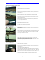
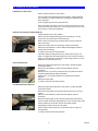
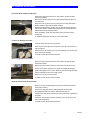
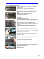
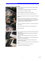
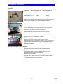
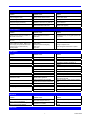
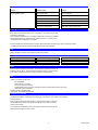
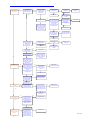
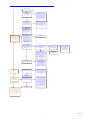
 asi 750/840/925 Service Manual Offered by Signature Automotive Products asi 750/840/925 service manual
Removal and Installation of Glass Panel
Cycle the glass panel to the vent position.
Remove the left and right hand mechanism cover using an interior trim
clip removal tool.
Deflect the glass tension spring downwards from the glass bracket.
Note: Make sure that you set the spring onto the control links so not to
scratch the track section.
Remove the two (2) rear 8mm nuts and loosen the two (2) front 8mm
nuts on the glass panel bracket.
Remove glass panel from the vehicle.
To install, reverse the removal procedures.
Glass Panel Adjustment
Remove the left and right hand mechanism cover using an interior trim
clip
li removall ttool.
l
FRONT: Adjust the front of the glass panel by loosening the two (2) front
T-25 torq screws. Adjust the glass panel so the front edge is flush with
the trim ring and tighten the screws.
REAR: Adjust the rear panel by loosening the rear T-25 torq screw.
Adjust the rear edge so the glass panel is between 1mm higher or flush
with the trim ring, then tighten the T-25 torq screw.
Fore and Aft Adjustment
Put the glass in the vent position.
Remove the left and right hand mechanism cover using an interior trim
clip removal tool.
Loosen all four (4) 8mm retaining nuts.
Put the glass in the closed position and center the glass to the opening.
Adjust and tighten the rear 8mm retaining nuts one at a time. Place the
glass panel in the vent position and tighten the front 8mm retaining nuts.
After the glass panel is adjusted, re-install the mechanism covers.
1
Service
asi 750/840/925 service manual
Initialization of Glass Panel
Place the glass panel in the vent position.
Once the glass has reached the full vented position, release and hold
the vent button. The glass will kick back, indicating re-initialization has
been completed.
Cycle the glass panel to insure proper function.
Note: If the glass stops short in its travel, hold the vent button for six (6)
seconds until the glass panel cycles. After the glass panel cycles, it will
be necessary to repeat the initailization.
Removal and Installation of Wind Deflector
Position the panel in the open position.
Remove the left and right track plug by removing two (2) T-10 torq
screws from each side and lift out the track plug.
NOTE: Observe the track plug orientation before removal; label and
mark if necessary.
Inspect foam tape seal on the track plug. Replace if necessary.
Remove the wind deflector. Pull the deflector tabs slightly inboard to
release from the molding.
To install, reverse the removal procedure.
CAUTION: When installing the track plug, make sure the plugs' rear
edge is not higher then the mating edge of the track section (screws too
tight), or that the attaching screws are not protruding (screws too loose).
Otherwise, the panel will retract into
Front Guide Removal
Remove the glass panel while in the vent position. (Follow the glass
removal procedure.)
Remove the wind deflector. (Follow the wind deflector removal
procedure.)
Remove the two (2) T-25 torq screws from the pivot plate and remove
the glass panel bracket by sliding it rearward.
Remove the T-10 screw that holds the front guide and control link
together.
Remove the front guide.
To install, reverse the removal procedure.
Cam Slide Mechanism Removal
Remove the glass panel while in the vent position. (Follow the glass
removal procedure.)
Remove the front guide control link by removing the two (2) T-10 torq
screws.
Remove the wind deflector. (Follow the wind deflector removal
procedure.)
Remove the front guides. (Follow the front guide removal procedure.)
Cycle the cable mechanism approximately 1/2" from the front edge of the
track by holding the vent button until the cam slides forward.
Disengage the cable end from the cam sides.
NOTE: Using a small pointed tool, pull the cable end out of the cam
slide sideways.
To install, reverse the removal procedure.
2
Service
asi 750/840/925 service manual
Rear Panel Slide and Bushing Removal
Remove the glass panel while in the vent position. (Follow the glass
removal procedure.)
Remove the tension spring from the glass panel bracket and place on
the control link.
Remove the two (2) front T-25 torq screws from the front glass panel
bracket. Slide the glass panel bracket rearward.
Replace the slide bushing, making sure the slide bushing is placed on
the cam link with the rounded side rearward and the curved side down.
All parts should be properly lubricated.
When reinstalling, make sure the bushing does not rotate causing
interference.
To install the glass slide, reverse the removal procedure.
Control Link Removal Procedure
Cycle the glass panel into the vent position.
Remove the left and right hand mechanism cover using an interior trim
clip removal tool.
Remove 9mm nuts and the T-10 torq screw retaining control link to front
guide and trough assembly.
To install, reverse the removal procedures.
Drain Trough Removal Procedure
Remove the glass panel while in the vent position. (Follow the glass
removal procedure.)
Remove the control link. (Follow the control link removal procedure.)
Using a screw driver, deflect the rear guide tab inboard, allowing the
guide to disengage from the notch. Slide the guide and trough assembly
forward, allowing access to the trough screws.
Remove the two (2) T-20 torq screws.
To install, reverse the removal procedures.
Removal of Rear Guide Shoe Assembly
Remove the drain trough assembly. (Follow the complete mechanism
removal procedures.)
Remove the rear guide shoe by sliding the guide forward until it
disengages from the track section. Slide the track plug out.
Install the new rear guide, making sure that the leaf spring is attached to
the guide.
CAUTION: The leaf spring must be attached to the rear guides for the
unit to function properly.
To install, reverse the removal procedures.
3
Service
asi 750/840/925 service manual
Removal and Installation of Cable Assembly
Remove the glass panel while in the vent position. (Follow the glass
removal procedure.)
Remove the rear cam. (Follow the cam removal procedure.)
Detach the headliner from the side rail, carefully separating the headliner
from the rails or factory hardboard headliner, allowing access to the drive
assembly.
Remove the three (3) T-20 torq screws attaching the motor to the
housing.
Deflect the motor gear away from the drive cables.
Pull the cable from the track section.
Lubricate the new cable assembly prior to installing.
Insert the drive cables into the track section, by pushing the cables into
the drive tubes.
Install the cable ends to the cam slides.
Slide the left and right hand cams rearward so that the rear portion of the
cam assembly aligns with the notch in the track section.
Install the front guide. (Reverse the front guide removal procedure.)
Attach the wind deflector. (Reverse the wind deflector removal
procedure )
Install the motor assembly. (Reverse the electric drive assembly removal
procedure.)
Cycle the unit making sure that the cables are properly aligned.
To install the control link and panel, reverse the removal procedure.
Motor Removal / Install
Loosen the headliner in order to gain access to the motor and SCU.
Operate the sunroof to the full vent position. If the motor can not operate
electronically use override on the motor.
Disconnect the negative side of the vehicle's battery and the sunroof
motor wire from the SCU.
To remove the motor, loosen and remove the three (3) T-20 screws and
pull the motor away from the mounting bracket.
Install the new motor with the insert screws provided.
Reconnect the vehicle's battery and the sunroof motor wire to the SCU
Switch the ignition on and operate the sunroof to the open position.
Close, vent and re-initialize the SCU (follow the reinitialization process.
Refer to the trouble shooting guide.)
Reinstall the headliner.
4
Service
asi 750/840/925 service manual
Removal and Installation of Glass Panel Seal
Remove the glass panel while in the vent position. (Follow the glass
removal procedure.)
Using a suitable tool, separate the seal tape from the glass panel.
NOTE: Be careful not to damage the molding.
Remove all residue from the old seal from the molding.
Clean the molding with alcohol to remove any grease or oily film.
Apply an adhesive promoter to the surface, which will make contact with
the tape.
Apply the new replacement seal slightly past the front center. Wrap
completely around, overlapping the starting point. Cut both seals at the
same time in the center of the glass. Dab a small amount of proper
bonding adhesive to the cut ends of the seal to
NOTE: To avoid adhesive contamination, do not remove tape backing
until necessary.
Once the seal is applied, press firmly to assure proper adhesion.
I t ll th
Install
the glass
l
panel.
l
Sunshade Removal and Installation
Remove the left and right hand mechanism cover using an interior trim
clip removal tool.
Remove the glass panel while in the vent position. (Follow the glass
removal procedure.)
Remove the control link assembly. (Follow the control link removal
procedure.)
After the rear guide is disengaged, move the trough assembly forward,
allowing access to the trough screws.
Remove the two (2) T-20 torq screws that are holding the trough
assembly to the rear guides.
Slide the sunshade forward through the slot on the right hand side of the
track.
Remove the sunshade through the sunroof opening.
To install, reverse the removal procedures.
5
Service
asi 750/840/925 service manual
Electrical
Connector
Power with ignition off
Wire Number 1 (Red )
Wire Number 2 (Green)
Power with ignition on
12V
Ground
12V
Ground
Wire Number 3 (Blue)
ZERO V
12V
Reconnect the vehicle's battery and test cycle the moonroof to verify it is
fully functional. Initialize SCU (see the initialization procedure).
SCU Removal / Install
Disconnect the battery by disconnecting the negative side of the battery.
Loosen the headliner in order to gain access to the motor and SCU.
Using a T-20 torq driver remove the mounting screw.
Disconnect the power, switch and motor wires from the SCU.
Remove the SCU by sliding it towards the motor.
Install the new SCU by locating the mounting tab and pushing the SCU
away from the motor. Reinstall the T-20 screw.
Reconnect the power, switch and motor wires to the SCU.
Switch the ignition on and operate the sunroof to open, close and vent
positions and re-initialize the SCU (follow the reinitialization process).
Reinstall the headliner.
Removal and Installation of Sunroof Switch
Depending on where the switch is located, pull downwards and
disengage the switch from the retaining bracket.
Pull the switch down, exposing the wire harness and connector.
Disconnect the switch from the wire harness.
Replace the defective switch.
Cycle the sunroof, making sure all functions are in working condition.
To reinstall, follow the removal procedure.
6
Service
asi 750/840/925 service manual
Mechanical Failures
Problem
Possible Cause
Solution
Panel misaligned LH/RH
Timing of drive cables incorrect
Re-time drive cables
Panel misaligned side to side
No contact of seal to one side
Loosen panel screws and reposition panel
Glass panel stops prematurely
Obstacle in mechanism or guide rail
Remove obstacle
Cable ratcheting
Check the motor and cable tube at
motor bracket and motor insert
Align cable tube to motor bracket and
reinstall motor properly
Problem
Possible Cause
Solution
Operating of the sunroof is possible, no
auto close, no one touch
SCU in degraded mode due to
malfunction
Reinitialize SCU by running glass panel to full
vent position
SCU makes clicking noise but panel will
not move
Low voltage
Check power supply
Panel is sliding too slowly. With a 13.5v
power supply, the panel should not take
more than 7sec. to close from fully
opened position
Weak battery
Misaligned panel creating drag
Weak motor
Dirty mech
Change or replace motor
Clean and grease mechanism or replace
Problem
Possible Cause
Solution
Front guide rattle
Worn front guide
Replace front guide
Substrate rattle
Clips loose
Silicone substrate and secure push pins
No pad between substrate and housing
Pad between headliner and bottom of
housing
Loose or misadjusted
Tighten and adjust
Hits glass and rattles
Add felt pad to glass
Hits front cross member
Readjust and add felt pad
Sunshade rattle
Sunshade handle hits water trough
Add velcro to plastic handle
Wire Harness rattle
Harness rattles against kit
Drain Channel rattle
Check if insulation tape is applied
between drain channel and sunshade
Tighten wire ties
Tape and secure wires
Check for felt pads on drain channel, add felt
pads
Rattle in motor area
Loose screws on motor
Tighten screws or replace
Self tapping neb screws
Screw is stripped
Replace or retap screw hole
Screw is loose
Tighten screws
Possible Cause
Solution
Electrical Failures
Rattling Noise
Wind deflector rattle
Wind Noise
Problem
Excessive wind noise when the glass
panel is in the closed position
Excessive wind noise when the glass
panel is in the full open position
Panel seal not tight to trim ring
Application in to vehicle
Readjust the panel or replace seal or fill out
seal
Reference pre-program glass stop in owner's
manual
Water Leaks
7
Trouble Guide
asi 750/840/925 service manual
Problem
Possible Cause
Solution
Water coming through panel opening
area or headliner is wet
Blocked drain tubes
Remove material
Improper routing of drain tubes
Re-route or replace drain tubes
Front cross member seal broken
Seal seam
Rear end caps seal broken
Reseal end caps using silicone
Glass panel out of adjustment
Adjust glass panel
Improper seal compression
Adjust seal or replace seal section
Testing Electrical Components
Make sure that the Inalfa asi Moonroof is connected to a 12V source during the test
of electrical components .
If the moonroof is installed in a car, the battery needs to be connected and operable.
During the test period, the ignition/accessory switch must be on. This test can be
accomplished with a voltage meter or test light.
Inspect and make sure that the fuses are not blown. Refer to the filled out portion of the owner's manual for location.
The cable harness and motor inspection requires the removal of the headliner.
Fuse
Refer to the filled out portion of the owner's manual for the location.
Wire Harness SCU to Battery
Connector
Wire number 1 (red)
Wire number 2 (black)
Wire number 3 (blue)
Power on wire if ignition is off
12V
Ground
ZER0 V
Power on wire if ignition is on
12V
Ground
12V
Motor
Disconnect the motor wire from the SCU. If the mechanism is jammed, remove the
motor from the rear beam. Use a double wire of sufficient length, connect it directly
to the battery and inspect the motor for proper operation in both directions.
SCU
Testing is covered in the electronic
ASI 750/840/925
Moonroof does not function
One Touch function inoperative
Programmable position cannot be programmed (push both switch buttons at the same time)
Auto Close function inoperative
The SCU must be reinitialized after
replacement. Proceed with the electronic
Reinitialization of the SCU
The first time the SCU is connected to the power supply, the maximum vent position must be defined.
Turn the ignition on
Open the glass panel to the full vent position, using continuous mode. Continue to
vent the glass panel until the glass panel moves (a few mm) to close and returns
(max five (5) seconds).
To complete the reinitialization process, the glass panel must be moved to the fully
opened position using One Touch™ mode.
8
Trouble Guide
asi 750/840/925 service manual
Is the motor running
with ignition
switched on?
no
yes
Is the switch
illuminated? (ignition
contact switched on)
no
Is the fuse of the red
contact wire blown?
(ignition contact
switched on)
no
yes
Power (12v) on red
contact wire of SCU?
yes
Has the fuse been
replaced before?
yes
no
Replace Fuse
yes
no
Break or bad contact in
wire harness between
fuse and SCU. Replace
wire harness or solve
bad connection.
yes
Fuse smaller than
20 amps?
Mount a fuse of 20
amps (red)
no
Short circuit in wire
harness, replace wire
harness
Disconnect motor from yes
SCU. Check the correct
functioning of the motor
by connecting the motor
wires to a separate
power source.
Is the motor functioning
in both directions?
yes
Re-connect motor
connector to SCU and
replace switch.
nofunctioning
Is the roof
normal?
Switch failure
no
SCU failure. Replace
SCU
no
Remove motor from
sunroof frame. Is the
motor functioning in
both directions?
yes
Mechanical problem.
Check mechanism for
obstruction or failure.
no
Motor broken. Replace
motor.
Is the fuse of the blue
contact wire blown?
(ignition contact
switched on).
yes
yes
Has the fuse been
replaced before?
no
Mount a fuse of 5
amps (blue)
Short circuit in wire
harness. Replace wire
harness
no
yes
yes
no
Replace Fuse
Replace switch.
Problem solved?
Fuse smaller than 5
amps?
Switch failure
no
Power (12v) on blue
contact wire of SCU?
yes
Break or bad contact in
flat cable between fuse
and SCU. Replace wire
harness or solve bad
connection.
no
Break or bad contact in
wire harness between
fuse and SCU. Replace
wire harness or solve
bad connection.
Is the motor running
in both directions?
no
yes
Disconnect motor from
SCU. Check the correct
functioning of the motor by
connecting the motor wires
to a separate power
source.
Is the motor functioning in
both directions?
yes
yes
Re-connect motor
connector to SCU and
replace switch.
Is the roof functioning
normal?
no
no
Switch failure
SCU failure, replace SCU
no
yes
Remove motor from
sunroof frame. Is the
motor functioning in
both directions?
Mechanical problem.
Check mechanism for
obstruction or failure
no
Motor broken.
Replace motor.
yes
Is the motor
running
normal?
no
Is the motor running for
only a short time after
operating the switch?
yes
yes
SCU not properly
mounted, gearwheel
disconnected from cable.
Remove SCU and mount
properly. Problem solved?
yes
Problem solved
no
Search for bad connection
in wire harness
Is the one touch
functioning?
no
yes
Re-initialize SCU by
running the sunroof to
max tilt and keep on
pushing the switch. After
3 seconds the SCU
confirms re-initialization
by kicking back a few mm.
Problem solved?
yes
Problem solved
no
Replace SCU
Is it possible to open
the roof in its
maximum opened
position?
yes
no
yes
Re-initialize SCU by
running the sunroof to
max tilt and keep on
pushing the switch. After
3 seconds the SCU
confirms re-initialization
by kicking back a few mm.
Problem solved
9
Trouble Chart
asi 750/840/925 service manual
Problem solved?
no
yes
The unit does not kick
back confirming reinitialization
Cancellation of tilt activated
preventing the sunroof
going into tilt. De-activate
funtion by pushing <tilitopen-open-tilt-tilt-open>
directly after switching off
the ignition contact.
no
Can the sunroof be
placed in all positions
using the manual
override on the motor?
yes
Blue wire is not connected
via ignition. Search for
another contact wire which
is switched by the ignition
contact.
yes
Problem solved
yes
Sunroof does not close
after completing the 5 retry
closing motions
no
Mechanical problem.
Obstruction or failure of
mechanism. Remove
obstruction or solve
failure.
no
The roof is
experiencing false
reversal during one
touch or auto close
operation
yes
Re-initialize SCU by
running the sunroof to
max tilt and keep on
pushing the switch. After
3 seconds the SCU
confirms re-initialization
by kicking back a few mm.
Problem solved?
no
False reversal also
occurs during one touch
closing motion
no
no
Is the auto close
functioning?
no
yes
Power (12v) on blue wire
SCU with ignition off?
yes
yes
no
Remove glass panel
and test the sunroof.
Problem solved?
no
High resistance of
mechanism whereby the anti
trap protection is activated.
Readjust glass panel and
clean and lubricate
mechanism with Molycoat
based grease.
False reversal only
occurs during auto-close
yes
yes
Glass was adjusted
incorrectly introducing
high resistances.
Mount glass panel
and adjust properly.
Obstacle in
mechanism.
High resistance of
mechanism whereby the
anti trap protection is
activated. Readjust glass
panel and clean and
lubricate mechanism with
Molycoat based grease.
Blue wire is not connected
via ignition. Search for
another contact wire which
is switched by the ignition
contact.
Replace SCU
Can the
Programmable
Position be set?
no
yes
Does the unit start to
move when both switch
buttons are depressed?
no
yes
The buttons are released
too soon. The panel can
start moving when both
buttons are pushed because
of slight timing differnces.
The motion will be stopped
as soon as the second
button is operated activating
the programming mode.
Replace SCU
Electronics Fully Tested and
okay. Remaining problems
are not caused by the SCU,
motor, wire harness or
switch. Please continue with
the mechanical trouble
shooting guide.
10
Trouble Chart