1
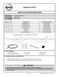
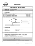
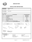
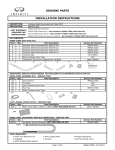
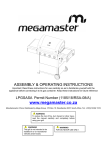
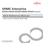
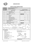
GENUINE PARTS
INSTALLATION INSTRUCTIONS
DESCRIPTION:
APPLICATION:
PART NUMBER:
KIT CONTENTS:
Item
A
B
C
D
E
F
Illuminated Kick Plate
Maxima (2010)
999G6 MX000
QTY
1
1
1
3
21
6
Description
Kick Plate, FR LH
Kick Plate, FR RH
Wire Harness
Posi-Tap
Tie Wrap
Urethane Foam Tape
Service Part Number
999G6 MX001
999G6 MX005
Not a service part
Not a service part
Not a service part
Not a service part
*** Components C thru F in are located in Harness Bag
A
B
C
E
D
TOOLS REQUIRED:
● Nylon
N l
R
Removall T
Tooll
● Phillips Head Screw Driver
● Fl
Flash
h Light
Li ht
● Soft cloth
F
● Specialty tool for BCM (optional)
● Alcohol
PRE-INSTALLATION CAUTION/NOTES
● Dealer installation recommended.
recommended Instructions may refer to Service Manual.
Manual
● Installation may require special tools.
● This
partt iis to be in
installed
Thi p
t lled att a surface
f e temperature
tempe t e no warmer
me than
th n 65-100F
65 100F
CAUTION
● This accessory must only be installed as specified in these instructions.
● Ensure at all times that parts are securely fitted and will not compromise the safe function of
vehicle systems.
Page 1 of 18
999G6 MX000 II REV 08/20/10
INSTALLATION OVERVIEW:
F
D
B
D
C
D
A
Plate-Kicking, FR RH
BCM
Plate-Kicking, FR LH
CRITICAL STEPS:
● Locate LH mark on back side of part for LH side installation. Locate RH mark on back side
of part for RH side installation. Mis-installation can cause improper fit.
● Follow posi-tap instructions
Page 2 of 18
999G6 MX000 II REV 08/20/10
VEHICLE PREPARATION:
F
CAUTION
● Dealer Installation Recommended. Instructions refer to steps described in Service Manual.
● Please read these instructions carefully before installing this product for correct installation.
● Please DO NOT use or install the part in ways other than what is described in this
instruction manual.
● If problem occurs during installation, please contact Nissan dealer where you purchased the
product.
1) Apply Park Brake.
2) Make sure the shift lever is engaged in "P" position.
3) Record customer Radio Presets.
Preset
1
2
3
A
B
C
4)
5)
6)
7)
4
5
6
Use seat and floor protection.
Open hood of the vehicle.
Disconnect the negative battery terminal to prevent short circuits during installation.
This part is to be installed at a vehicle body surface temperature of 65-100°F.
CAUTION
● Take care not to scratch or damage any component during the removal or re-installation
process.
● Trim pieces found to have witness marks or broken clips are not to be re-installed.
Removal Sequence
1. Instrument Panel Side Mask LH
2. Instrument Driver Lower
3. Front Kick Plate Outer LH
4. Front Kick Plate Inner LH
5. Dashboard Side Lower Panel LH
6. Center Console Lower Panel LH
7. Instrument Cluster Trim Panel
8. Instrument Cluster
9. BCM
10. Front Kick Plate Outer RH
11. Front Kick Plate Inner RH
12. Dashboard Side Lower Panel RH
13. Center Console Lower Panel RH
7, 8, 9
1
2
6
13
12
5
11
4
10
3
Page 3 of 18
999G6 MX000 II REV 08/20/10
INTERIOR PROCEDURE:
Fig 1
1)
Remove the Instrument Panel Side Mask LH
a) Pull the Instrument Panel Side Mask toward
the door opening to release.
Fig 1
NOTE:
Repeat on opposite side of vehicle.
Fig 2a
2)
Loosen the Instrument Driver Lower
a) Remove the fuse panel cover
Fig 2a
b) Remove the (1) Phillips screw behind
the fuse panel cover.
Fig 2b
c) Pull the Instrument Lower Panel rearward
in the vehicle to release the (8) clips.
Fig 2c
d) Remove the harness connector and hose
for Instrument Lower Panel (optional).
Fig 2b
Fig 2c
Page 4 of 18
999G6 MX000 II REV 08/20/10
INTERIOR PROCEDURE:
(continue)
F
Fig 3
3)
Front Kicking Plate Outer (LH) Removal
a) Start at Rear Edge and pull up by hand.
b)
(May need to use tool to pry up end)
Fig 3
There are (4) clips that secure the part.
NOTE:
Repeat on opposite side of vehicle.
Fig 4
4)
Front Kicking Plate Inner (LH) Removal
a) Starting at Rear Edge, pull up and
b)
toward seat using nylon tool.
Carefully lift part up moving from rear
c)
to front.
Fig 4
There are (8) clips that secure the part.
NOTE:
Repeat on opposite side of vehicle.
Fig 5
5)
Remove Dashboard Side Lower Panel
a) Starting at the floor, pull part toward
the foot pedals. There are (3) clips
that secure the part. Fig 5
Weather Seal (LH) Removal
b) Start at in center of door opening and
pull up.
c)
Pull seal away from the body between the
b-pillar lower and the side mask. Fig 5
NOTE:
Repeat on opposite side of vehicle.
Page 5 of 18
999G6 MX000 II REV 08/20/10
INTERIOR PROCEDURE:
(continue)
F
Fig 6
6)
Remove the Center Console Lower Panel LH
a) Pull the Center Console Lower Panel
toward the foot pedals. There are (3) clips
that secure the part.
Fig 6
NOTE:
Repeat on opposite side of vehicle.
Brake Pedal
Clips
Fig 7
7)
Remove the Instrument Cluster Trim Panel.
a) Remove the (2) Phillips screws at the
lower left and right corners. Fig 7
b) Pull the panel towards the driver's seat
and free from the Instrument Panel.
NOTE: Do not disconnect the switches.
Rotate the panel to the right, out
of the way.
Fig 8
8)
Remove the Instrument Cluster
a) Remove the (3) Phillips screws. One on
top and one at the left and right lower
corners. Fig 8
b) Do Not disconnect the Cluster. Rotate
the assembly to the right and up out
of the way.
NOTE: Disconnect a white electrical connector
on the left side of the cluster if necessary
to allow the assembly to rotate.
Page 6 of 18
999G6 MX000 II REV 08/20/10
INTERIOR PROCEDURE:
(continue)
F
Fig 9
9)
Remove the BCM from the dash assembly
a) Remove the (2) screws securing the
BCM bracket to the dash assembly.
Fig 9
b) Rotate BCM to access connectors
NOTE: There may be special one-way screws
used to secure the BCM to the vehicle.
Use a 'Grab-it' or other tool to remove
the special screws.
CAUTION
● Color(s) given in illustration(s) are for reference only. Use location(s) where color deviates
● If a vehicle wire is being used by another accessory and a posi-Tap is present, tap the
accessory wire NOT the vehicle wire.
Fig 10
BCM
Cable Tie
10) Route 3 wire end of harness to the BCM
a) Use a large cable tie to guide the black
wire harness to the cavity where the BCM
is housed. Loop the wire through the end
of the cable tie and pull it up to the BCM
cavity. Fig 10
Black Harness
Page 7 of 18
999G6 MX000 II REV 08/20/10
INTERIOR PROCEDURE:
(continue)
F
11) Tap the Red wire of the Kick Plate Harness to the Pink/White wire, located in cavity 4 of the M17
connector at the BCM. Fig 11
a) See steps 12-16 for Posi-Tap installation instructions.
Fig 11
Yellow/Red
Cavity 4
Pink/White
Empty
Cavity View
Fig 12
12) Tap Vehicle Wire. Fig 12
a) Remove cap (slot side) from tap body.
b) Slide cap around vehicle wire.
c) Tighten the tap TIGHT with finger pressure.
NOTE: Do not re-use the tap for subsequent
re-installation
Fig 13
13) Inspect the tap to ensure correct installation.
Fig 13
NOTE: Avoid putting pressure on the vehicle
wire and tap for the rest of the installation
Page 8 of 18
999G6 MX000 II REV 08/20/10
INTERIOR PROCEDURE:
(continue)
F
Fig 14
14) Tap accessory wire
Fig 14
a) Remove tap (non-pierce) side from tap.
b) Remove protective stub from black wire.
c) Insert the black wire through the non-pierce
side opening.
d) Spread individual strands into a fan shape.
e) Insert wire into the tap body and ensure
that it is all the way in.
f) Tighten the tap TIGHT with finger pressure.
Fig 15
15) Confirm installation of the tapped wire
Fig 15
a) Inspect the tap to ensure correct installation.
NOTE: Avoid putting pressure on the vehicle
wire and tap for the rest of the installation
Fig 16
16) Secure the tap. Fig 16
a) Secure the tapped wire on the non pierced
side to the body of the posi-tap with
electrical tape ( ≥ 2 revolutions).
b) Secure the body to harness where the
vehicle wire is being tapped with electrical
tape ( ≥ 2 revolutions).
l i
)
Page 9 of 18
999G6 MX000 II REV 08/20/10
INTERIOR PROCEDURE:
(continue)
F
17) Tap the Yellow wire of the Kick Plate Harness to the Sky Blue wire, located in cavity 58 of the M18
connector at the BCM. Fig 17
a) See steps 12-16 for Posi-Tap installation instructions.
Fig 17
Cavity 58
Sky Blue
Cavity View
Green/Red
White
18) Tap the Black wire of the Kick Plate Harness to the Red/Black wire, located in cavity 32 of the M18
connector at the BCM. Fig 18
a) See steps 12-16
12 16 for Posi-Tap
Posi Tap installation instructions.
Fig 18
Green
Empty
Cavity View
Cavity 32
Red/Black
Page 10 of 18
999G6 MX000 II REV 08/20/10
INTERIOR PROCEDURE:
(continue)
Driver Door
F
Fig 19
19) Re-Install the BCM to the dash assembly
a) Secure Harness to BCM Cable with
(1) tie wrap. Fig 19
b) Rotate BCM back into position.
c) Re-install (2) Phillips screws.
Fig 20
20) Secure Wire Harness
a) Secure Harness to vehicle harness
with (2) tie wraps.
b) Maintain a 150mm-200mm gap between
tie down points. Fig 20
Tie Wrap
BCM
Driver Door
BCM
Wire going to Driver Foot Well
Tie Wrap
Page 11 of 18
999G6 MX000 II REV 08/20/10
INTERIOR PROCEDURE:
(continue)
F
21) Secure Wire Harness
a) Route the wires down to the floor. Keep the wire harness to the door side of the Park Brake.
Keep the wire harness behind the Fuse Block.
b)
Secure the wire harness with (2) tie wraps where the harness splits.
c) Maintain a 150mm-200mm gap between tie down points. Fig 21
Fig 21
Fuse Block
Tie Wraps
Park Brake
Fig 22
22) Secure Wire Harness
a)) Route
R
short
h
harness
h
to driver
d i
side
id
kicking-plate.
b)
Secure harness with (2) tie wraps.
c) Maintain a 150mm-200mm gap between
tie down points. Fig 22
Tie Wrap
Park Brake
Black Wiring Cable
Page 12 of 18
999G6 MX000 II REV 08/20/10
INTERIOR PROCEDURE:
(continue)
Black Cable
Black Wiring Cable
F
Fig 23
23) Pull back Carpet
a) Starting in corner near the driver door,
pull back carpet toward driver's seat
and expose White Carpet Backer.
Fig 23
Fig 24
24) Bull back Carpet
a) Starting in corner near the passenger door,
pull back carpet toward passenger's seat
and expose White Carpet Backer.
Fig 24
Glove Box Handle
Fig 25
Black Cable
25) Secure Wire Harness
a) Loosely route wire harness under carpet
and over transmission tunnel (under center
console) to passenger side.
b)
Foam Tape
Tie Wrap
Secure harness with (1) foam tape above
white carpet backer. Keep wire off of white
carpet backer. Secure wire along black
cable with (2) tie wraps. Maintain a 150mm
-200mm gap between tie down points.
Fig 25
White Carpet Backer
Page 13 of 18
999G6 MX000 II REV 08/20/10
INTERIOR PROCEDURE:
(continue)
F
Fig 26
Foam Tape
26) Secure Wire Harness
a)
Glove Box Handle
b)
c)
Tie Wrap
Loosely route wire to passenger side
kicking-plate.
Secure wire with (3) foam tapes above white
carpet backer. Keep wire off of white
carpet backer. Maintain 150mm-200mm
gap between tie down points.
At passenger side vehicle harness secure
harness with (1) tie wrap. Fig 26
White Carpet Backer
Black Wiring Cable
Fig 27
Glove Box
27) Secure Wire Harness
a)
Loosely secure harness at connector to
vehicle harness with (1) tie wraps.
b) Maintain a 150mm-200mm gap between
tie down points. Fig 27
Black Wiring Cable
Tie Wrap
Page 14 of 18
999G6 MX000 II REV 08/20/10
INTERIOR PROCEDURE:
(continue)
F
Fig 28
The Procedure below shows the installation for
LH Side. Repeat Procedure for RH side.
Front RH & LH parts are not interchangeable.
28) Prepare Harness Connector
a) Remove tape wrap from harness.
Fig 28
Kick Plate
Tape Wrap
Fig 29
29) Install Front Kicking Plate Outer (LH)
a) Clean vehicle body with alcohol and
allow to dry.
b) Starting from the front, align clips on
the kicking plate with the body holes.
Fig 29
NOTE:
Be careful not to damage clips during
installation.
Fig 30
I
ll F
Front Ki
Kicking
ki
Pl
Plate O
Outer (LH)
30) Install
a)
b)
c)
Place Kick Plate over holes.
Cover top of the kick plate with cloth
to prevent damage.
Press down directly above each clip
to engage. Push to snap.
Fig 30
NOTE: Be careful to install left kicking plate
to left side of vehicle. Mis-installation can
cause improper fit.
Page 15 of 18
999G6 MX000 II REV 08/20/10
INTERIOR PROCEDURE:
(continue)
Connectors
F
Fig 31a
Tie Wrap
Kick Plate Controller
Tie Wrap
Harness
Retainer
Front
The Procedure below shows the installation for
LH Side. Repeat Procedure for RH side.
31) Connect the Kicking Plate to the Harness
a) Connect the Connectors.
Fig 31a
b) Make sure that wiring passes over door
flange and forward of the black plastic
harness retainer.
Fig 31a
c) Secure harness with (2) tie wraps.
Maintain a 150mm-200mm gap between
Fig 31b
Excess Harness
d)
e)
f)
tie down points.
Fig 31a
If you have excess harness, loop the
extra length to the vehicle harness with (1)
tie wrap. Fig 31b
Tighten all tie wraps.
Cut excess tie wrap.
Front
Page 16 of 18
999G6 MX000 II REV 08/20/10
CHECK BEFORE PART REINSTALLATION
1)
F
Please check that the installation has no problem.
a) confirm the connection of the connectors.
b) confirm wire harness attachment to vehicle.
c) confirm that there are no loose parts that would cause rattle.
FUNCTION CHECK
1)
2)
Re-connect battery negative terminal.
Confirm "MAXIMA" text is illuminated with either Front door in the opened position.
REINSTALLATION OF REMOVED PARTS
1)
2)
3)
All removed vehicle parts have been reinstalled.
Clean interior of vehicle.
Verify both kick plates are properly installed with no gaps to body.
CAUTION
● Use caution when re-installing interior components to avoid damage, scratch, or breaking
of mounting clips.
VEHICLE CHECK
1)
2)
3)
4)
5)
6)
7)
8)
Remove all tools from the vehicle.
Inspect re-installed interior trim parts for proper panel fit.
Turn ignition to ON position.
position
Reset radio presets to the recorded setting.
Confirm proper radio operation.
Initialize sun roof, and power window operation.
Turn ignition to OFF position.
Check and clear trouble codes.
CAUTION
● During restoring, please use caution as not to cause the stacking of the vehicle harness,
or damage any parts.
Page 17 of 18
999G6 MX000 II REV 08/20/10
MECH
F
Green/Red
Pink/White
Yellow/Red
Sky Blue
Empty
White
Empty
Red/Black
/
Green
BCM Connector
Yellow
Y
w
Red
1 LED
1 LED
Red
Black
B
k
BCM Connector
Driver's side Illuminated Kick Plate
Passegner's side Illuminated Kick Plate
Page 18 of 18
999G6 MX000 II REV 08/20/10