1
GO TO TABLE OF CONTENTS
438A Folder / 438B Feeder V4
Service Manual
ISSUE 2008/05
071-28558-401 (A)
438A SERVICE MANUAL
071-28558-401 (A)
ISSUE 2008/05
COVER
PAGE 1
438A SERVICE MANUAL
071-28558-401 (A)
ISSUE 2008/05
COVER
PAGE 2
While every care has been taken in the preparation of this manual, no liability will be accepted by GBR Systems Corporation arising out of any inaccuracies
or omissions.
All service documentation is supplied to GBR Systems Corporation external customers for informational purposes only. GBR Systems Corporation service
documentation is intended for use by certified, product trained service personnel only. GBR Systems Corporation does not warrant or represent that such
documentation is complete. GBR Systems Corporation does not represent or warrant that it will notify or provide to such customer any future changes to
this documentation. Customer’s service of equipment, or modules, components, or parts of such equipment may void any otherwise applicable GBR
Systems Corporation warranties. If Customer services such equipment, modules, components, or parts thereof, Customer releases GBR Systems
Corporation from any and all liability for Customer’s actions, and Customer agrees to indemnify, defend, and hold GBR Systems Corporation harmless from
any third party claims which arise directly or indirectly from such service.
Prepared by:
GBR Systems Corporation
Technical Publications
Copyright 2008 by GBR Systems Corporation. All rights reserved, GBR Systems Corporation.
Copyright protection claimed includes all forms or manner of copyrighted materials and information now allowed by statu tory or judicial law or hereinafter
granted, including without limitation, material generated from the software programs which are displayed on the screen such as styles, templates, icons,
screen displays, looks, etc.
Printed in the United States of America.
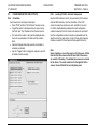
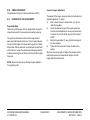
USING THE MANUAL
1. TABLE OF CONTENTS
Each capitalized alphabetic character represents a major division within the manual (Section A).
Under each major division, the capital letter is followed by a number. This represents a subdivision of the major section (Section A1. is a subdivision of
A.).
Under each subdivision, an alphanumeric combination is followed by a decimal and a lower case letter. This represents a smaller division under a
subdivision (Section A.1a. is a subdivision of A.1, Section A.1a1 is a subsection of A.1a).
Each major section of the manual begins with page 1 and is numbered in sequence through that section only. Section A begins with page 1, section B
begins with page 1, etc. This manual is divided into Section A through I. A detailed table of contents is located on the first page of each section.
SECTION A
INTRODUCTION
Machine Orientation
Machine Specifications
Run and Setup Screens
Engineering Values
Line Code Read with Setup Screens
Laser Bar Code Read w/Setup Screens
GBR OMR Reader Setup
Read Zone Diagrams
Postal Meter Setup Presets
Software Updates Via Email
SECTION B
PREVENTATIVE MAINTENANCE
SECTION C
ELECTRONICS
SECTION D
PROBLEM ANALYSIS
Test Screens
General Solutions to Problems
Error Codes
Possible Causes of Errors
Repair Checkout Procedures
SECTION E
ADJUSTMENT & REPAIR INFORMATION
Feeder
Accumulator
Folder Section
Transfer Conveyor
SECTION F
MACHINE SCHEMATICS
SECTION G
INTERFACE TO OPTIONAL EQUIPMENT
Connecting to an Inserter
438A SERVICE MANUAL
071-28558-401 (A)
ISSUE 2008/05
COVER
PAGE 3
438A SERVICE MANUAL
071-28558-401 (A)
ISSUE 2008/05
COVER
PAGE 4
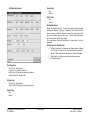
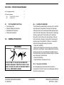
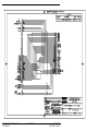
2. HEADERS / FOOTERS
The information listed along the left edge refers to the machine, the manual type, and the part number and revision level for that manual
The particular issue listed in the center is an internal tracking device.
The top line of information along the right side states the title of the particular section. The bottom line lists the section and the page number within that
section.
3. LIST OF CHANGES IN THIS REVISION
ECN: 9606
Issue Date: 3/5/2008
Revision: This is a first release for the 438A V4 Service Manual
Software supported by this revision: XXX-XXXXX-XXX
Changes incorporated in this manual:
Section
Change
New Release
4. SECTION ISSUE DATES
Sect A XXXX/08
Sect B XXXX/08
Sect C XXXX/08
Sect D XXXX/08
Sect E XXXX/08
Sect F XXXX/08
Sect G XXXX/08
438A SERVICE MANUAL
071-28558-401 (A)
ISSUE 2008/05
COVER
PAGE 5
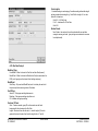
A.8
SECTION A – INTRODUCTION TO THE 438 V4
SECTION A – INTRODUCTION TO THE 438 V4 ........................................... 1
A.1
RELATED MANUALS............................................................................... 2
A.2
INTRODUCTION TO THE MANUAL .................................................... 2
A.3
INTRODUCTION TO THE MACHINE .................................................. 2
A.3a
Feeder Section .......................................................................................... 2
A.3a Feeder Section ................................................................................................... 5
A.3b
Accumulator Section................................................................................. 7
A.3c
Folder Section........................................................................................... 8
A.3d
Exit Conveyor........................................................................................... 8
A.3d
Exit Conveyor........................................................................................... 9
A.3e
Emergency Stop Interlocks ..................................................................... 10
A.4
MACHINE SPECIFICATIONS .............................................................. 12
A.5
RUN SCREEN ........................................................................................... 13
A.6
KEYBOARD OPERATION..................................................................... 14
A.7
SYSTEM SETUP SCREEN...................................................................... 15
A.7a
Setup ....................................................................................................... 16
A.7b
Feeder Setup ........................................................................................... 17
A.7c
Accumulator ........................................................................................... 18
A.7d
Folder...................................................................................................... 19
A.7e
Xfer Cvyr (Transfer Conveyor) Setup ................................................... 19
A.7f
Infeed Setup............................................................................................ 20
A.7g
Line Read Setup 0................................................................................... 21
A.7h
Bar Read Setup 0.................................................................................... 22
A.7i
Inserter Setup 0....................................................................................... 22
A.7j
Inserter Setup 1....................................................................................... 23
A.7k
Inserter Setup 2....................................................................................... 24
A.7l
Inserter Setup 3....................................................................................... 25
A.7l
Inserter Setup 3....................................................................................... 25
A.7m Inserter Setup 4....................................................................................... 26
A.7j
Engineering Values (Password Protected) .............................................. 27
A.7k
ExitComm............................................................................................... 27
438 V4 OPERATOR & SERVICE MANUAL
071-28558-401
ENGINEERING VALUES........................................................................ 28
A.9
LINE CODE READ SYSTEMS OPTION............................................... 32
A.9a
Introduction ............................................................................................. 32
A.9b
438 Line Read Setup Screens (GBR & B+H) ......................................... 32
A.9b
438 Line Read Setup Screens (GBR & B+H) ......................................... 33
A.9c
Line Read Setup 1 ................................................................................... 33
A.9d
Line Read Setup 2 ................................................................................... 36
A.9e
Line Read Setup 3 ................................................................................... 39
A.9f
Line Read Setup 4 ................................................................................... 41
A.10
LASER BAR CODE READ OPTION ..................................................... 42
A.10a
Laser Safety........................................................................................ 42
A.10b
Bar Code Basics ................................................................................. 42
A.10c
Adjusting Your Microscan MS-911 ................................................... 43
A.10d
Setting the 438 to Read Laser Bar Code ............................................ 44
A.10e
Bar Read Setup 1................................................................................45
A.10f
Bar Read Setup 2................................................................................47
A.10g
Adjusting the Paper Guide Belts ........................................................ 47
A.10h
Bar Read Setup 3................................................................................48
A.10i
Bar Read Setup 4................................................................................49
A.12
READ ZONE DIAGRAMS .......................................................................50
A.13
POSTAL METERING .............................................................................. 51
A.13a
Three Meter Example......................................................................... 54
A.13b
Two Meter Example........................................................................... 54
A.14
ISSUE 2008/05
SOFTWARE UPDATES VIA EMAIL .................................................... 55
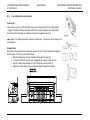
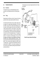
INTRODUCTION
SECTION A – PAGE 1
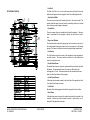
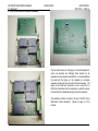
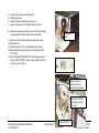
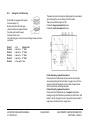
Hopper and Feeder Paper Guide Rails:
A.1
RELATED MANUALS
The two stainless steel rails mounted on the hopper are adjustable via a
locking handle at the rear. At the front they interlock with the feeder side rails,
then lock to shafts running across the machine. Both sets of rails should be
adjusted together.
The following manuals are available for the 438.
071-28855-402 438A & 438B PARTS MANUAL
A.2
INTRODUCTION TO THE MANUAL
Paper Hopper
This manual is intended for service technicians and is organized to enhance
preventive maintenance, troubleshooting, and repair of the 438. Installation of
the 438 is also described.
Note: The exact screens and functionality are software version dependent.
Specific features may be available or not, or have default settings according to
the software version.
A.3
INTRODUCTION TO THE MACHINE
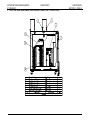
A.3a Feeder Section
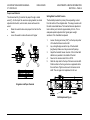
The 438’s feeder is bottom fed, top loading for continuous operation, with a
capacity of 1500 sheets (20 lb bond or offset paper).
The Paper Hopper supplies the bottom fed friction feeder continuously while
the operator loads paper from the top. It has 4 mounts (2 each side, with set
screws) in which the hopper slides. The Hopper Table is located behind the
feeder. Paper level in the hopper is controlled by a demand switch. The
position of the hopper table determines how well the demand switch will
perform this function. During normal operation a metal wand rests on the
incoming paper. As more paper is needed, the metal wand will fall low enough
to close the demand switch. This activates the creeper conveyor motor to drive
the hopper belts, conveying paper into the feeder area under the paper level
detector. When the proper level of paper is attained the wand will have been
lifted enough to open the switch, shutting off the creeper conveyor motor.
Creeper Conveyor
The Creeper Conveyor is comprised of two black rubber belts driven by a
motor located on the bottom side of the hopper. Controlled by a paper level
detector, the motor is activated when the detector indicates that paper is low.
438 V4 OPERATOR & SERVICE MANUAL
071-28558-401
ISSUE 2008/05
INTRODUCTION
SECTION A – PAGE 2
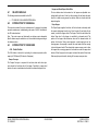
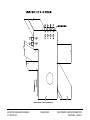
Layout of Model 438 V4 (Operator / Left Side View)
438 V4 OPERATOR & SERVICE MANUAL
071-28558-401
ISSUE 2008/05
INTRODUCTION
SECTION A – PAGE 3
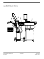
Layout of Model 438 V4 (Top View)
438 V4 OPERATOR & SERVICE MANUAL
071-28558-401
ISSUE 2008/05
INTRODUCTION
SECTION A – PAGE 4
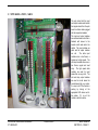
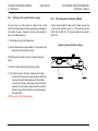
Feed Belt
A.3a Feeder Section
The Main Feed Belt is a one inch wide beige timing belt which drives the
bottom sheet of paper under the singulator roller. Also called Singulator Belt.
Auxiliary Feed Belts
These are two urethane belts located either side of the main feed belt. The
auxiliary feed belts assist the main feed belt, smoothing variations in frictional
drive (correcting erratic feeding of the paper).
Drive Rollers
These two orange rollers are located directly below the singulator. These are
used in conjunction with the singulator to ensure only one sheet is fed at a
time.
Paper Level Detector
This demand switch monitors the paper going into the feeder area. Its job is to
limit and demand the amount of paper that is most productive to the feeding
process. The Paper Level Detector monitors the paper through a metal wand.
Feed Sensor
The Feed Sensor monitors the output of the singulator for proper singulation or
non-feed of paper. The sensor module is located next to the double detect
sensor in the singulator area.
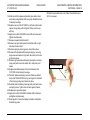
Double Detect Sensor
The double detect sensor is ultra sonic sensor which does not require electrical
adjustment. The mechanical position of the sensor is 40mm above the
mounting plate +/- 2mm. The sensor determines that two sheets have been
fed by a field induced between the two pages.
Feeder Speed Encoder
A blue-clad optical encoder located on the right side of the upper pullout shaft.
It is used to detect feeder run speed.
Feed Clutch
Electrical clutch which engages the feed belt at a signal from the controller.
Read Sensor
A through beam sensor located on the reader bracket which is mounted to the
crossbar. A reader logic board interprets variation in light intensity as it is
reflected off the paper and code marks.
438 V4 OPERATOR & SERVICE MANUAL
071-28558-401
ISSUE 2008/05
INTRODUCTION
SECTION A – PAGE 5
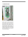
Singulator
438 V4 OPERATOR & SERVICE MANUAL
071-28558-401
ISSUE 2008/05
INTRODUCTION
SECTION A – PAGE 6
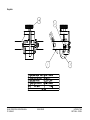
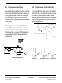
A.3b Accumulator Section
Accumulator Sensor
The accumulator is fed paper from the singulator, assembling groups of one to
seven documents. When the document package is complete, it is fed to the
folder.
Stacking Ramps
The Accumulator Sensor indicates presence or absence of a package in the
accumulator. It also monitors package discharge when the dump clutch has
been engaged.
Stack Sensor
Stacking Ramps are the plastic wedges which position successive pages of a
Located at the edge of the ramps, the stack sensor indicates the documen t has
cleared the stacking ramps.
Sensor Modules
The Sensor Module for the Accumulator and Stack Sensors are accessible by
removing the right side accumulator cover.
7
Sensor, Reflector
Part of Sensor
6
Belt, Conveyor
186-031033097
5
Brake
121-26564-000
4
Stacking Ramps
186-032051604
3
Stacking Rollers
177-28468-600
2
Accumulator Presence Sensor
057-32041-000
1
Accumulator Stack Sensor
057-32041-000
Item
Description
Part #
Part List
document package in order.
Stacking Rollers
These are used to stop the paper and hold it in position. When released, the
Stacking Rollers drive the collected pages out of the accumulator.
Dump Brake
This prohibits the rollers from releasing paper from the accumulator.
Dump Clutch
This activates the stacking rollers, releasing the accumulated pages.
438 V4 OPERATOR & SERVICE MANUAL
071-28558-401
ISSUE 2008/05
INTRODUCTION
SECTION A – PAGE 7
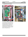
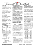
A.3c Folder Section
The folder is capable of placing 1 to 7 sheets in a C, Z, or double V
configuration. It is fed by the Accumulator Section.
Buckle Plates
Manual adjustable plates which set the distance of the fold from the edge of the
paper.
Rollers
Used to nip the paper as it is buckling, creating the fold.
Folder Drive Motor
A motor which drives all folder shafts and rollers and the upper and lower
dump shafts on the accumulator.
Folder Speed Encoder
An encoder, located on the exit roller shaft, which provides a folder speed
signal.
438 V4 OPERATOR & SERVICE MANUAL
071-28558-401
Folder Section Representation
ISSUE 2008/05
INTRODUCTION
SECTION A – PAGE 8
A.3d Exit Conveyor
This monitors the presence of paper packages in the first station of the transfer
conveyor.
Straight Conveyor (AM52 Delivery)
This is an optional stand alone straight conveyor that enables the 438 to be
used in a “stand alone” configuration.
Transfer Conveyor (8.5” and 11” versions)
Transfer Conveyor Discharge Sensor and Module
This monitors the discharge of paper packages from the output conveyor. It
acts to confirm the processing of specific documents.
Transfer Conveyor Package Presence Sensor and Module
438 V4 OPERATOR & SERVICE MANUAL
071-28558-401
ISSUE 2008/05
INTRODUCTION
SECTION A – PAGE 9
A.3e Emergency Stop Interlocks
The main E-stop located on the operator panel will interrupt power to the
conveyors and folder when pressed down. This switch must be twisted to
bring it back to its original upper position.
An extra contact is provided on this E-stop switch which is routed to pins 30
and 33 of the Inserter Connector located on the adaptor plate on the end of the
cabinet. This will affect an E-stop to an external device when these contacts
are wired to the E-stop circuit on that external device (e.g. Pinnacle).
A connection to the 438 interlock string has been provided on pins 28 and 29
of the same Inserter Connector which allows an external device (e.g. Pinnacle)
to E-stop the 438. For this E-stop string to be functional a blue jumper across
pins 24 and 25 of Module #7 on the I/O Board must be removed. If this E-stop
string is not used this jumper must be in place.
Pin 11 of this connector also provides an "Interlock Sense" signal to an
external device.
There are five (5) safety interlock switches that will interrupt power to the
conveyors and folder whenever a cover is opened:
2. Accumulator Cover Interlock
3. Folder Upper Cover Interlock
1. Feeder Cover Interlock
438 V4 OPERATOR & SERVICE MANUAL
071-28558-401
ISSUE 2008/05
INTRODUCTION
SECTION A – PAGE 10
Figure 2
4. Folder Exit Interlock
5. Transfer Conveyor Cover Interlock
438 V4 OPERATOR & SERVICE MANUAL
071-28558-401
ISSUE 2008/05
INTRODUCTION
SECTION A – PAGE 11
A.4
Versions 2—with intelligent transfer conveyor interface to gripper arm of
inserter’s insert station.
MACHINE SPECIFICATIONS
Listed below are specifications for the 438:
Version 3—with a buffering, intelligent transfer conveyor interfaces to an open
feed station of inserter The GBR 438-3 can also convert an intelligent,
continuous form mail inserting system to a cut sheet operation.
Throughput
Speed: Max. 30,000 documents per hour
Material
Paper Weights: 20# (75 GSM) to 24# (90 GSM), Inquire for heavier weights
Paper Size: 7” x 7" (178 mm x 178 mm) to 11” x 14” (305 mm x 356 mm)
Controller: Adjustable operator's panel with readout and touch screen access
to all system functions. System is microprocessor controlled with
self-diagnostics and error display including double, misfeed, and jam detection.
Electrical Service
Loading Capacity: 1,500 sheets of 20# bond.
208 volts, 3 phase-Y, 20 amp, 4 pole, 5 wire grounding - use NEMA L21-20R
Fold Types; "C", "Z", "V" & DOUBLE "V"
220 volts, 1 phase, 20 amp,
Porosity: 20 Gurley seconds
1,000 BTU/hr
Stiffness: 20 Lb. Stock, 170-225 Gurley Stiffness Units
Fuse List - Refer to Section D10
3 pole, 4 wire grounding - use NEMA L14-20R
Dimensions (includes feeder, accumulator, folder, and transfer
conveyor)
24 Lb. Stock, 250-300 Gurley Stiffness Units
Cross Grain Stiffness: 20 Lb. Stock, 8~125 Gurley Stiffness Units
Length: 106" (mm)
24 Lb. Stock, 12~150 Stiffness Units
Width: 26" (mm)
Moisture Content 4-6% by Weight
Height: 58” (mm)
Weight: Net approx. 725 Ibs. (kg)
Components
Read Options
Feeder: Bottom feed, top loading for continuous operation.
Line Code (B+H or GBR)
Optical Reader: Optical code reading for group batch recognition, sequencing
and double printing control of 1 to 12 document groups. Larger group batch
setting available upon request.
Bar Code
Folder: 4 plates.
Group selector: Manual group selection for 1 to 12 sheets.
Counter Modes: Total count, batch count, resettable count.
Output Conveyor Options:
Version 1—with shingling output conveyor/stacker
438 V4 OPERATOR & SERVICE MANUAL
071-28558-401
ISSUE 2008/05
INTRODUCTION
SECTION A – PAGE 12
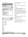
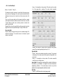
A.5
Status – Displays machine status such as “Power Off”.
RUN SCREEN
This screen is displayed continuously for informational purposes until “Test” or
“Setup” is selected.
(See Section A.7 for “Setup” Screens)
(See Section D “Problem Analysis” for “Test” screens.)
Run – The current screen.
Test – Press to enter diagnostic screens (for more information, refer
to Section D).
Setup – Press to enter setup screens (for more information, refer to
Section A.7).
Release Brakes – Releases/Applies Accumulator and Feed Brakes
to allow jam clearing.
Information Displayed:
Revision (Software) and Build Date – top line
Packages – Total package counter. Reset in System Setup. Also
resets during bootup.
Sheet – Displays the # of sheets in the accumulator.
Total Sheets – Displays the number of sheets fed from the time the
system was powered up. Resets on machine power down.
Pack Rate – Used to monitor throughput of the 438. Calculated at
every pack dumped from accumulator (not averaged).
Demand Rate– Displays the package demand rate from the inserter.
Calculated at every demand signal transition (not averaged).
Date and Time - (not functional at this time)
EOG – Displays end of group (ready for dump).
Group – Displays group sequence number after read.
Page – Displays page sequence number after read.
Total Diverts – Displays the number of diverts since the start of
the run.
Batch - displays “Batch Sheet” or “Batch Package” count, resets on
sequential stop
Insert Marks – Displays which insert are selected after each
read.
Control Marks – Displays any controls marks, such as IM (Ink
Mark) after read.
Diagnostic – Internal timing
Monitor Events – Displays event history, however, entire list is lost
when power is turned off.
438 V4 OPERATOR & SERVICE MANUAL
071-28558-401
ISSUE 2008/05
INTRODUCTION
SECTION A – PAGE 13
RESET
Press after interlock is broken or E-stop condition
E – STOP
Press to shut down all motors on the 438 in emergencies
E-Stop must be twisted to bring back to original position
Lifting any cover will also shut down all motors on the 438
A.6
KEYBOARD OPERATION
START / STOP
Press to start all motors and enter ready mode
Press while in ready mode to shut down the 438
CYCLE
Press quickly to feed one sheet
Repeat until EOG on display is “1”, DUMP
Press and hold CYCLE to start continuous feeding
PURGE
Press after manually filling the accumulator to discharge package into the
folder
438 V4 OPERATOR & SERVICE MANUAL
071-28558-401
ISSUE 2008/05
INTRODUCTION
SECTION A – PAGE 14
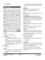
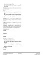
A.7
SYSTEM SETUP SCREEN
Press Setup while in the Run screen.
This screen provides access to all 438 setup screens.
Press Run to return to the “Run” screen.
Note: Normal factory settings are in bold font.
438 V4 OPERATOR & SERVICE MANUAL
071-28558-401
ISSUE 2008/05
INTRODUCTION
SECTION A – PAGE 15
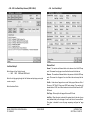
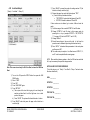
A.7a Setup
Package Size
Max Pages in Accumulator. 1 to 12
For Read, 1 greater than max expected (5 for the LineCode test set). Or
number of fixed pages with no read.
Reader Type.
Line, Bar, None (Off)
Exit Conveyor Type
Inserter Online. By demand.
Gripper Arm setup.
See Inserter Setup 1 for Open Station or
Inserter Offline. Selecting this allows the inserter to run independent of the
438 without physically detaching.
Hopper Fill. Select "HOPPER FILL" when the inserter will be taking the folded
documents from a hopper. With or without demand. See Eng. Value 20. With
no Inserter.
Conveyor. with or without demand. See Eng. Value 20, (selects whether or
not to ignore the demand signal), with no Transfer Conveyor (Xfer Cvyr). Exit
at Folder with Folder Exit Sensor for straight shingling style of stacking
conveyor.
Batch Processing
Package Count “Reset”
Resets total package count (“Packages”) found in Run screen. This value will
also reset automatically on power down of machine.
Total Sheets “Reset”
Sheet: Select job size by entering the number of sheets to run. When
selected the “Batch Off” button changes to “Set Sheets”. When “Sheet” is
selected and a batch size entered, the machine will complete the package
containing the last sheet.
Package: Select job size by entering the number of packages to run. When
selected the “Batch Off” button changes to “Set Packs”
Batch Process “Reset” (On/Off status is also displayed)
Resets the “Total Sheets” or “Total Packs” (depending on which option was
selected) found in the Run screen. This value will also reset automatically after
the sequential stop determined by the batch size entered. A sequential occurs
when the last pack is accumulated, the machine stops feeding, purges the
accumulator and transfer conveyor to the inserter, then powers down.
Off: Disables Batch Processing
“Batch Off” Button: Changes to “Set Packs” or “Set Sheets” depending on
the option selected. Press to enter batch value, a numeric keyboard is
displayed, then press “=” to set. Batch value is displayed to the left of the
button. This button is not available when Batch Processing “Off” is selected.
Sheet Length
Double “Arrow Up” button increments, in tenths of an inch, to standard sheet
sizes 7”, 8.5”, 11”, 14”, A4, and A5
“Single Arrow” buttons adjust sheet length in tenths of an inch
438 V4 OPERATOR & SERVICE MANUAL
071-28558-401
ISSUE 2008/05
INTRODUCTION
SECTION A – PAGE 16
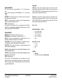
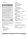
A.7b Feeder Setup
Timed
“Pulse Feed Time” must be set when using this option.
Clutch is off at lead edge of page, on after Time (for Timed).
Read
Clutch is off at lead edge of page, on after read received.
Pulse Feed Time
Use when “Timed” is selected
Higher the number, the larger the gap between sheets.
Double Detect Enable
Select to have the 438 detect double feeds. Optical is a thru-beam sensor
whereas Ultrasonic detects the interference of air between two or more sheets
fed.
Deselect if paper stock is causing false double detects.
Pulse Feed
Deselect to engage clutch for the entire pack. AKA “Stream Feed”.
When selected the feeder will place a larger gap between the sheets by turning
the clutch on and off for each page fed.
Page End.
Clutch is off at lead edge of page, on again at trail edge of page.
438 V4 OPERATOR & SERVICE MANUAL
071-28558-401
ISSUE 2008/05
INTRODUCTION
SECTION A – PAGE 17
A.7c Accumulator
Accumulator Max
th
Select up to 12 sheets maximum, the 438 will shut down on the 13 sheet fed
into the accumulator. This function prevents damage to the folder.
12 may be selected when it is not desirable to have a package split into
th
subsets. The 438 will still shutdown on the 13 sheet. The operator must
clear the accumulator and manually process the package.
Accumulator Type
Flat or Normal
438 V4 OPERATOR & SERVICE MANUAL
071-28558-401
ISSUE 2008/05
INTRODUCTION
SECTION A – PAGE 18
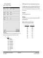
A.7e Xfer Cvyr (Transfer Conveyor) Setup
A.7d Folder
Folder Enable
Leave selected (not functional at this time).
438 V4 OPERATOR & SERVICE MANUAL
071-28558-401
ISSUE 2008/05
INTRODUCTION
SECTION A – PAGE 19
Feed Max Low:
Pertains to a friction or suction feeder wherein a setting can be made to set the
number of sheets left in the feeder. It will set the number and prevent the
feeder from running out completely preventing the operator from having to
reload from scratch.
Printer / Cutter-RA / Cutter-ST:
This setup section allows the operator to set a time delay for each of the
following feeding devices. The function of the delay is the same for each
device; it enables the document some amount of time to feed into the
accumulator or it will declare an error.
Full Delay – Enter time of delay desired
IF42 Jam – Enter time of delay desired
Finish Delay – Enter time of delay desired
Infeed Response – Enter time of delay desired
Creeper On – Enter time of delay desired
A.7f
Infeed Setup
Infeed Type:
Off
Creeper: Select when using the standard 2000 sheet creeper conveyor.
Bulk: 470 type bulk loader with on/off control by software monitoring the paper
demand switch.
Cutter – 1 Guillotine type cutter/feeder
Printer Flat sheet printer feeder
Cutter-RA A guillotine cutter set in right angle configuration feeding onto a
right angle or turning device then feeding into the accumulator.
Cutter-ST A cutter feeding directly into the accumulator.
438 V4 OPERATOR & SERVICE MANUAL
071-28558-401
ISSUE 2008/05
INTRODUCTION
SECTION A – PAGE 20
A.7g Line Read Setup 0
screens.
Pressing the OK button in each setup screen saves those
parameters to the job number selected.
Reset Job
Press this button to reset the job parameters to the default values for the job
selected.
Line Calibration
Note: Used only for B+H Line Read or GBR Line Read. Do not try to use this
feature for GBRCode8 or GBRCode16, it will not work.
This function will calibrate the line code reader for proper location of marks for
interpretation of code. Before pressing “Line Calib” make sure Reader Type
“Line” in System Setup screen is selected. “Read” must be selected in Feeder
Setup and all sensors must be properly adjusted. All Line Read Setup screens
must be setup. Select Calibration “On” in Line Read Setup 2 before starting
and “Off” when finished.
Get Version:
Pressing this button results in printing the software version of the LineReader
on one line of the “Monitor Events” window.
B+H Sensors
Note: For use with either B+H or GBR Line Read.
Note: Refer to Section A.9 for an explanation of GBR Line Code Read.
Enables viewing the action of the sensor signals for diagnostic purposes.
Setup 1 – Refer to Section A.7j
Setup 2 – Refer to Section A.7k
Monitor Events Window: It is intended to give the operator or technician
feedback regarding the status of what is occurring.
Setup 3 – Refer to Section A.7l
Setup 4 – Refer to Section A.7m
Select : “Line Read Type”
B&H Read
GBR Read
GBR Code 8
GBR Code 16
Job Number
System will save all the parameters for up to 10 line code jobs. To program:
select a job number, set all settings for the job in Line Read Setup 1, 2, and 3
438 V4 OPERATOR & SERVICE MANUAL
071-28558-401
ISSUE 2008/05
INTRODUCTION
SECTION A – PAGE 21
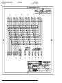
A.7h Bar Read Setup 0
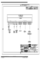
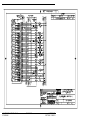
I/O Rack #1 (RIGHT)
Refer to Section A.? for setup information.
A.7i
INSERTER
Inserter Setup 0
POSTAR
(U.S. Application)
(Typical European Application)
1-04 = Separation Sol #
Postar Data Bit #1
1-05 = Separation Sol #1
Postar Data Bit #2
1-06 = Separation Sol #8
Postar Data Bit #3
1-07 = Shingle Conv Motor
Postar Kicker
1-08 = Separation Sol #2
Postar Data Bit #4
1-09 = Separation Sol #3
Postar Data Bit #5
1-10 = Separation Sol #4
Postar Data Bit #6
1-11 = Separation Sol #5
Postar Data Bit #7
1-12 = Separation Sol #6
Postar Data Bit #8
1-13 = Separation Sol Env
Postar Data Bit #9
1-14 = Ink Marker Sol
Postar Data Bit #10
1-15 = Env Flap Sns Dis
Postar Data Bit #11
1-16 = Emergency Stop
Postar Data Bit #12
1-17 = Ins Station 1 Error
Postar Error Bit
1-19 = Postal Meter Divert
Postar Strobe Bit
1-22 = Cutter Jam Sensor
Postar Kick Sensor
Selection Direction is used for setting the protocol for insert station
numbering.
Postal Meter by Weight Enable – To select the Postal Meter
Stamping feature.
Setup 1 - Inserter Type & Feature Selection
Degrees – The Inserter Encoder updates this window as the inserter runs.
Home – The home position of the inserter can be seen shifting
from a zero to a one when the inserter is at home position.
Demand State
Setup 2 - Inserter Station Feature & Setup
Setup 3 - Postal Meter Feature Selection
Setup 4 - Inserter Encoder & Timing Setup
Inserter Protocol Type
Select either “Inserter”, or “Postar” The following I/O points have dual usage
depending on Protocol selected and interface PCB used (002d-08138 or 002d07599).
Operates in Demand Type “Switch” or “Degree” (see Inserter Setup 1),
3=ON, 0=OFF
Average Demand Rate
Diagnostic - averages Demand Rate over three cycles
ON Degrees
Degrees where demand goes on by either “Switch” or “Degree” demand
OFF Degrees
Degrees where demand goes off by either “Switch” or “Degree” demand
Inserter Monitor – Prints events
438 V4 OPERATOR & SERVICE MANUAL
071-28558-401
ISSUE 2008/05
INTRODUCTION
SECTION A – PAGE 22
A.7j
Inserter Setup 1
AC/DC – 420T/438 control of non-775 Inserter functions, station Select,
Envelope Disable, Envelope Flap Detect Disable, InkMark, Divert, Postal
Meters.
Demand Type
Switch : Select when demand signal is provided by a magnetic switch
Degree: Select when demand signal is provided by an encoder
Serial:
Select: when demand signal is provided through an RS232 interface by a
semi-intelligent inserter.
Bad Pack Stop Enable This box is defaulted “on” or “checked”.
The machine will stop on a bad pack and energize the bad pack indicator light
on the inserter. If unchecked or “off”, the machine will not stop on a bad pack.
Subset Method of inserting more than one accumulated packs into
one envelope on the inserter.
None: subset pause not used
Pause: inserter will not advance until the transfer conveyor feeds second pack
into open feed station.
Remove: inserter will not advance and permits the operator to remove the
packs deposited in the open feed station on the inserter.
Station Setup
Ins Stations
4, 6, 4+4, Choose Inserter configuration.
Xfer At Stations
Select “0” for GRIPPER, “1” - “9” for Open feed.
Normally set to "GRIPPER" (Inserter takes the folded document from
the 438)
Select "OPEN FEED" when the 438 will be placing the folded
documents directly on the inserter track. When using open feed,
selected number represents the number of stations prior to the first
insert station the package was placed.
Encoder Type
100 Tick or 36 Tick
Logic Type
775 – 420T/438 control of 775 Inserter functions, station Select,
Envelope Disable, Envelope Flap Detect Disable, InkMark, Divert,
Postal Meters.
438 V4 OPERATOR & SERVICE MANUAL
071-28558-401
ISSUE 2008/05
Note: Insert Station positions are referenced from the station at which the
documents are inserted into the envelope ("Insert Sta: 0"). Insert Station -1
would be the station downstream from Insert Station 0. Insert Station 1 is the
Insert Station upstream from Insert Station 0.
When set to “0” the station is always off.
When set to “9” the station is always on.
If a station is down the next station in line can be programmed to take its place.
Station Setup 1-4
Station Setup 5-8
Demand Degree
This is similar to setting dwell time on an engine. As the speed of the machine
is increased, home may be programmed at a position prior to 0 degrees
allowing for lag time in components at higher speeds.
Degrees may be set for 0 thru12,000 cycles per hour in 2,000 increments.
Note: Inserter degrees are reset to zero at the occurrence of a home pulse for
either inserter encoder.
INTRODUCTION
SECTION A – PAGE 23
A.7k Inserter Setup 2
Insert Station Vacuum is normally enabled at "100". This is the position of
the encoder (in degrees) at which vacuum is applied to the insert station.
Logical Shift is normally set to "On At: 90". This is used to carry the data
with the physical document.
Bad Package Stop is normally set to "On At: 80".
Kicker The Kicker routine is initiated by the extraction of an Ink Mark from
read data.
On Time Normally set to “On Time”: period of time in milliseconds that
the Kicker will be ON or energized.
Delay: Period of time in milliseconds to delay the Kickers ON time from
occurring. Range (0 to 990).
Station: The location on the deck of the inserter the Kicker will operate from
when selected. Range (0 to 25). “0” disables the kicker routine. Station is
referenced from the envelope insertion station in “Inserter” and from the first
station in “Postar” outside of the transfer conveyor. “Station” must be set to
greater than “0”.
Shift At: Logic shift for data adjustable to enable data to be shifted relative to
inserter Home position thereby ensuring the “Kick” comes at precisely the
correct moment.
Envelope Station Vacuum is normally enabled “At" 230. This is the
position of the encoder (in degrees) at which vacuum is applied to the
envelope hopper. “Station” is normally set at 2.
Envelope Flap Detect is normally set On at: 10, Off at: 350, and Insert
Station :1(this is the location of the flap detect).
Ink Mark is an optional device that places an ink mark in varying locations to
sort zip codes visually. "OFF At" is the number of chain movements AFTER
envelope insertion. Ink Marking is normally located at Station 7.
PM Divert is normally set “On At” 10, “Off At” 12 and is normally
located downstream from station 0.
438 V4 OPERATOR & SERVICE MANUAL
071-28558-401
ISSUE 2008/05
INTRODUCTION
SECTION A – PAGE 24
A.7l
Inserter Setup 3
Postal Meter 1 ( PM Divert in Inserter Setup 2) is normally set to "ON At”
200. This will enable the postal meter at the correct time. This value may need
to be adjusted if the postal meter doesn't place the postage in the correct
place. Postal Meter 2 (found in Inserter Setup 3) should then be set to 40
higher than the new meter 1 value and Postal Meter 3 should be 40 higher
than 2.
"OFF at” xx should be set to "10" for all three.
"Station: 0" is set to the value of the last chain section of the inserter after the
envelope stuffer and the turnover (04, 05, 06, 07, etc.), this is normally set to
"07" on a six station inserter.
"Point” xx selects the postal meter output line to the 438, this is normally set to
"0" for PM Divert, "1" for Postal Meter 2, and “2” for Postal Meter 3.
Weight Breaks
The 438 will total the weights of all documents, inserts, and the envelope and
then send it to the correct postal meter. Because you are setting the weight
breaks as well as the envelope, page, and insert we ights it is important to keep
the unit of weight (i.e. oz) consistent.
1 / 2 Enter the Weight Break of Postal Meter 1 to Postal Meter 2.
2 / 3 Enter the Weight Break of Postal Meter 2 to Postal Meter 3.
PM Divert, Postal Meter 2, and Postal Meter 3
NOTE ON POSTAL METER WEIGHING: The 438 can accommodate up to
three postal meters (PM Divert 2 and 3 are located in Inserter Setup 3). Based
on the values entered in "Weight Breaks", "Page Env Wts", "Ins 1-4 Wts", and
"Ins 5-8 Wts" (located in Inserter Setup 3) the document will be stamped by the
appropriate postal meter. The dollar value must be manually entered in the
postal meter.
The value you enter in the Postal Meter Weights can be any unit of measure as
long as it is consistent. If one weight break is set to reflect ounces, all other
settings must reflect ounces including the inserts and the postal meter itself.
Likewise, if one is set to reflect grams, they must all be set to reflect grams.
The numbers entered are relevant only to each other.
438 V4 OPERATOR & SERVICE MANUAL
071-28558-401
ISSUE 2008/05
Page Env Wts:
Page Enter the weight of the individual page, the 438 will sum the
weight of all pages automatically.
Env Enter the weight of an individual envelope.
Ins 1-4 Wts and Ins 5-8 Wts Enter the weight of each insert in
stations 1-4 and stations 5-8.
Refer to Section H.4 for an example of a Typical Postal Metering Setup Preset.
INTRODUCTION
SECTION A – PAGE 25
A.7m Inserter Setup 4
Pause Type
Switch or Degree
In Track Check
“On At” 180
Refer to Section H.4 for an example of a Typical Postal Metering Setup Preset.
Pause Degree –
0 (0 to 999)
On Deg 330
1 (1000 to 1999) On Deg 330
2 (2000 to 2999) On Deg 310
3 (3000 to 3999) On Deg 290
4 (4000 to 4999) On Deg 270
5 (5000 to 5999) On Deg 250
6 (6000 to 6999) On Deg 230
7 (7000 to 7999) On Deg 210
8 (8000 to 8999) On Deg 190
9 (9000 to 9999) On Deg 170
10 (10000+)
On Deg 150
438 V4 OPERATOR & SERVICE MANUAL
071-28558-401
ISSUE 2008/05
INTRODUCTION
SECTION A – PAGE 26
A.7j
Engineering Values (Password Protected)
A.7k ExitComm
Value
Type
For settings refer to Section A.8, for the default Engineering Values List.
Reset to Default
Press this button to reset only the current Engineering Value displayed back to
its default value. This value is changed on the display only. Pressing the “OK”
button saves the default value, “Cancel” exits and returns the Engineering
Value to the prior value.
0 No Comm
1 RR Donnelly 1
2 RR Donnelly 2
3 Pinnacle 1
4 Pinnacle 2
5 General
6 Tampa 1
7 Zaandam 1
8 Friedberg 1
Start Button
– Xmits test data in type selected. Displays response terminated by a CR,
LF. Press again to stop.
Event List
438 V4 OPERATOR & SERVICE MANUAL
071-28558-401
ISSUE 2008/05
INTRODUCTION
SECTION A – PAGE 27
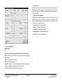
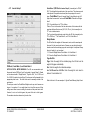
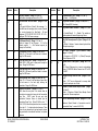
A.8
ENGINEERING VALUES
Number
These values are to be used as a starting point. These values may vary,
depending on type and weight of paper being processed, environmental
conditions, and system tolerances, in order to obtain optimal performance.
The password to enter this screen is factory set to “4444”. This password may
be changed at Engineering Value #27.
(Eng. Software Version)
Number (31264.008y3) (xxxxx.xxx)
Number
01
02
Value
20
40
Description
“Acc Feed Settle Time” (Range: 0 > 9995, Inc: 5)
Time(msec) after trail edge of last page passes
Accumulator stack sensor into Accumulator until
Accumulator clutch is fired.
“Acc Dump Done Time” (Range: 0 > 9995, Inc: 5)
Advance Feed ON: Time(msec) from “Accumulator is
going to dump” until next feed is started. A short value
advance feeds, before the pack moves from the
Accumulator. A longer time allows pack movement
detected at the Accumulator presence sensor to start the
next pack feed. Higher is safer, lower is faster, but
assumes pack leaves Accumulator.
Advance Feed OFF: Time(msec) from pack movement
at the detected at the Accumulator presence sensor to
start the next pack feed.
03
150
“Bar Read Time” (Range: 0 > 9995, Inc: 5)
Time(msec) waiting for reader response.
04
250
“Folder Exit Time”
(Straight Conveyor Only)
(Range: 0 > 9995, Inc: 5)
Time(msec) allowed for pack to reach the folder exit
sensor.
05
150
“Line Read Time” (Range: 0 > 9995, Inc: 5)
Time(msec) waiting for reader response.
06
10
“Xcvy Dump To Acc Dump Time” (Range: 0 > 9995,
Inc: 5)
Time(msec) from “Xcvy is going to move” until next
Accum dump is started.
438 V4 OPERATOR & SERVICE MANUAL
071-28558-401
ISSUE 2008/05
Value
Description
07
100
“Xcvy Clutch On Time” (Range: 0 > 9995, Inc: 5)
Time(msec) Xcvy clutch is on adjusted for number of
stations. Adjust up/down to place the last pack at the
Xcvy exit.
08
300
“Xcvy Into Station 1 Time” (Range: 0 > 9995, Inc: 5)
09
50
“Xcvy Outof Station 1 Time” (Range: 0 > 9995, Inc:
5)
10
400
“Folder Start To Conveyor Time” (Range: 0 > 9995,
Inc: 5)
Should be greater than Eng Value 04, Folder Exit Time
when Exit Type is Conveyor and not in test.
11
0
“Test Console Switch” (Range: 0 > 1, Inc: 1)
0 = turns off diagnostics only used in debug mode.
12
1
“Language Select” (Range: 1 > 2, Inc: 1)
1 = English. 2 = English
13
0
“Xcvy Package InOut Counter” (Range: 0 > 9995,
Inc: 5)
Max Number of packages expected in Xcvy. 0 disables
this check.
14
150
“Acc Dump Clutch On Time” (Range: 0 > 9995, Inc:
5)
Constant value Accumulator clutch is on adjusted for
speed. Adjust up so pack fully exits. Adjust down if next
pack is partially pulled under rollers.
15
5
“TouchScreen X Correction” (Range: -60 > 60, Inc:
1)
Constant value for touch sensing. Adjust up to move
sense right. Adjust down to move sense left.
16
-10
“TouchScreen Y Correction” (Range: -60 > 60, Inc:
1)
Constant value for touch sensing. Adjust down to move
sense up. Adjust up to move sense down
17
20000
“Paper Demand Time” (Range: 0 > 60000, Inc: 500)
Time(msec) waiting for paper stack switch in feeder to
be satisfied by infeed.
INTRODUCTION
SECTION A – PAGE 28
Number
Value
Description
Number
Value
Description
18
3
“Max Xcvy Stations” (Range: 2 > 6, Inc: 1)
Max Number of package positions in Xcvy “2-6”.
26
1
“Comm Hardware Type” (Range: 0 > 1, Inc: 1)
0 = Ziatech, 1 = WinSystems.
19
0
“Test ExitComm Test List Switch” (Range: 0 > 255,
Inc: 1)
0 = No extra ExitComm (Comm3) list messages. 1 =
Extra ExitComm list messages, times in msec, Demand
time, receive character (for Sure-Feed).
Bit level
assignment: (D7 D6 D5 D4 D3 D2 D1 D0. D7 > D1 =
unassigned D0 = ExitComm messages
27
4444
“Eng Values Password” (Range: 0 > 9999, Inc: 1)
4444 = Default(9561 is backup).
28
1
“Eng Values Enable Password” (Range: 0 > 1, Inc:
1)
1 = Enable(Default), 0 = Disable. This enables or
disables password to access Engineering Values.
20
0
“Exit Demand Switch” (Range: 0 > 1, Inc: 1)
Applies to Hopper Fill and Conveyor. 0 = No Exit
Demand required. 1 = Exit Demand required (for
Conveyor for Sure-Feed).
29
3
“Max. Exit Demand power On Cycles” (Range:0 > 99,
Inc: 1)
3 = Default. Number of inserter demand cycles before
438 outputs a package.
21
215
“Exit Demand Time Out” (Range: 0 > 999, Inc: 1)
Default 60 = 60 seconds to shut down on no demand.
Range 0 to 999 seconds.
30
2
“Bar Read Commport” (Cycle Machine Power)
(Range: 1 > 2, Inc: 1)
1 = Commport on CPU-PCB. 2 = (Default) Commport
on Serial Expansion PCB.
22
3000
“Xcvy Jam At Out Time” (Range: 0 > 9000, Inc: 10)
Default 3000 = 3000 msec to pass pack through exit
sensor. Range 0 to 9000 msec.
31
700
23
350
“Xcvy Jam At In Time” (Range: 0 > 9000, Inc: 10)
Default 500 = 500 msec to pass from folder to in sensor.
Range 0 to 9000 msec.
“System ON/OFF Time Cycles”. (Range: 500 > 700,
Inc: 5)
700 = Default. Debounce time in msec to acknowledge
cycling of POWER ON Button Presses from OFF to ON,
ON to OFF.
32
100
24
250
“Feed to Accum Time” (Range: 0 > 5000, Inc: 10)
Default 170 = 170 msec for the lead edge of paper fed at
the feed sensor to the lead edge entering the
accumulator. Range 0 to 5000 msec.
“Straight Conveyor Table ON Time” (Range: 5 > 500,
Inc: 5)
Default – 100. Time in milliseconds for conveyor table
ON time for each pack out of folder.
2
1
“Advance Feed Switch” (Range: 0 > 1, Inc: 1)
1=ON, allows the next pack to be started when the
Accumulator is supposed to dump plus the Accumulator
Dump Time.
0=OFF, starts the next pack after
Accumulator Presence Sensor is cleared plus the
Accumulator Dump Time. When EV #25 is set to “1”,
EV’s #1,2,23,24 should be adjusted as close to numbers
on the right of “→”to obtain optimal performance. These
values may vary depending on type and weight of paper
being processed, environmental conditions, and system
tolerances.
33
25
“Number of Double Detect Sample Counts” (Range:
1 > 4, Inc: 1)
Default = 2. Number of Double Detect Sample Counts
per sheet fed. 20msec sample rate.
34
0
“This EV intentionally left blank” (Range: 0 > 1, Inc:
1)
(Maximum Sheets Allowed to Accumulate moved to
“Accumulator Setup” in version 26412.051).
438 V4 OPERATOR & SERVICE MANUAL
071-28558-401
ISSUE 2008/05
INTRODUCTION
SECTION A – PAGE 29
Number
Value
Description
Number
35
80
“Feed Control Brake Delay Time” (Range: 0 > 160,
Inc: 10)
Default = 130 msec. Allows the page trail to leave the
singulator before the feed brake is applied. Delay
calculation based on sheet length, speed, and this
constant.
36
100
“Exit Comm Recvd Ack Time” (Range: 0 > 500, Inc:
10)
Default = 100msec. In Tampa 1 only, if no Ack
Response is received the machine errors out and resets
the comm. To try transmit again. (See EV#37 for
retries.) If set to =0 there is no Exit Comm Rcvd Ack
Timer check and no machine error
37
38
39
0
2
0
“Exit comm. Xmit Retries” (Range: 0 > 2, Inc: 1)
1 + Default. In Tampa 1 only, if no Ack Response is
received defined in EV#36, a retry is initiated and sends
a duplicate serial string. A range of 0->2 retries can be
indicated before the machine stops and displays the
error: “Exit Comm: No Message Response (E20801)”.
(See EV#36 for time setting). If set to =0, no retries are
initiated and if an Ack Response is not received in the
allotted time (EV#36), an error is generated.
“Barcode Reader (1=AS 30+, 2=MS911. 3=DL2031)”
(Range: 1 > 3, Inc: 1)
Default = 2. Will select the Start and Stop protocol for
either an Accusort Model 30+ or a microscan MS911.
1 = Accusort Model 30+ Bar Read Start Serial Trigger =
“S” Bar Read End Serial Trigger = “E”
2 = (Default) Microscan MS911 Bar Read Start Serial
Trigger = “<S>” Bar Read End Serial Trigger = “<J>”
3 = DataLogic 2031 Bar Read Start Serial Trigger = “S”
Bar Read End Serial Trigger = “E”
Value
Description
40
1
“Electronics? (1 = New, 0 = Old)” (Range: 0 > 1, Inc:
1, Default = 1)
1 = Default. Enables I/O configuration for new modular
electronics.
0 = Enables I/O for classic 420 two rack electronics.
41
0
“Sequential Stop Cycles (0=Off)” (Range: 0 > 99,
Inc: 1, Default = 0)
0 = Default. Normal operation.
1 – 99 = Demand cycles after package leaves transfer
conveyor that I/O point 0:16 “Inserter Stop” is asserted
upon the occurrence of a Sequential Stop command.
42
70
“Max. pages in track 1 – 200” (Range: 1 > 200, Inc: 1,
Default = 70)
Used with Flat Feeder configuration. Limits maximum
pages that can be accumulated in a track section.
43
0
“Feed Sensor interrupt (1=ON, 0+OFF)” (Range: 0 >
1, Inc: 1, Default = 0)
0 = Default. Utilizes poling method for input.
1 = Utilizes interrupt method for input.
44
1
“Accum Pack Bad: Set Pack After Bad Also”
(Range:0 > 1, Inc:1, Default = 1)
1 = Default. Upon occurrence of a bad pack, the next
pack processed is tagged as bad also until a good pack
is processed.
0 = Next pack, if no error in normal processing, is not
tagged as a bad pack.
45
1
“Accum Pack has Single: Set Pack Bad” (Range: 0 >
1, Inc:1, Default = 1)
1 = Default. Upon a single cycle accumulation of a pack
in the accumulator, the pack processed is tagged as
bad.
0 = pack is not tagged as a bad pack.
“Bad pack, Retain Selects? (1=Yes, 0+no)” (Range:
0 > 1, Inc: 1), Default = 0)
0 = Default. Normal operation. Upon Bad Pack, select
and evelope bits are set to zero.
1 = Upon Bad Pack, select and envelope bits are
retained.
438 V4 OPERATOR & SERVICE MANUAL
071-28558-401
ISSUE 2008/05
INTRODUCTION
SECTION A – PAGE 30
Number
Value
Description
Number
46
1
“Accum Pack Bad: Set Previous Pack Bad Also”
(Range: 0 > 1, Inc: 1, Default = 1)
1 = Default. Upon occurrence of a bad pack, the
previous pack processed is tagged as bad pack also.
(pack in Xfer conveyor).
0 = Previous pack, if no error in normal processing, is
not tagged as a bad pack.
47
0
“Flap Detect IO Inversion (1=Invert, 0+Normal)”
(Range: 0 > 1, Inc:1, Default = 0)
0 = Default. Normal operation.
1 = Logic inversion for the signal. (Incserco mailcrafter).
48
0
“Intrack Sns Method (0=Normal, 1=Subset-pause)”
(Range: 0 > 1, Inc: 1, Default = 0)
0 = Default. Normal operation.
1 = Support for Subset-Pause operation utilizing both
Transfer Conveyor out Sensor and Intrack/Open Feed
Sensor to track folded subsets in same track.
49
0
“Accum pack Bad: Set Divert By Read Bit” (Range:
0 > 1, Inc:1, Default = 0)
0 = Default. Normal operation.
1 = Sets Divert by Read bit if the pack is not valid.
50
0
“ReadLess Read Mode” (Range: 0 > 1, Inc: 1,
Default = 0)
0 = Default. Normal operation.
1 = Special error recovery routine when using Demand
Feed type “Read first” in barcode for FPF-35.
51
1
“First pack Dumped Error Enable” (Range: 0 > 1,
Inc: 1, Default = 1)
1 = Default. Normal operation.
0 = Disables setting bad pack on first pack processed
after startup or purge.
52
1
“Feed & Accum pack Error Enable” (Range: 0 > 1,
Inc:1,Default = 1)
1 = Default. Normal operation.
0 = Disable setting bad pack on Feeder or Accum.
Errors.
438 V4 OPERATOR & SERVICE MANUAL
071-28558-401
ISSUE 2008/05
53
Value
0
Description
“Inserter Error Pause mode Switch” (Range: 0 > 7,
Inc: 1, Default = 0)
0 = Default. Normal operation
1 = Pulse I/O (1:16) upon a read or processing error.
2 = Pulse I/O (1:16) upon a Demand Feed occurrence
while accumulating a package.
3 = combines functions 1 & 2
4 = Steady state on I/O (1:16) upon a Demand Feed
occurrence while accumulating a package.
5 = combines functions 1 & 4
6 = Illegal combination.
7 = Illegal combination.
INTRODUCTION
SECTION A – PAGE 31
A.9
LINE CODE READ SYSTEMS OPTION
A.9a Introduction
The Line Code Recognition System is capable of decoding line code marks
that are on 1/10”, 1/8" or 1/6" spacing. There can be as many as 25 mark
locations in a bank with a possibility of two banks per each channel of Line
Code marks.
A Single Line Code Recognition card supports input information from two
probes. The second probe is a optional feature. The system is limited to having
only one of the two probes active at any one time. If more than one channel of
Line Code marks is required to be recognized on a single document, each
additional channel requires another Line Code Recognition system.
Read Probe Assembly
438 V4 OPERATOR & SERVICE MANUAL
071-28558-401
ISSUE 2008/05
INTRODUCTION
SECTION A – PAGE 32
A.9b 438 Line Read Setup Screens (GBR & B+H)
A.9c Line Read Setup 1
Demand Feed
Line Read Setup 0
Normal - The machine will demand feed on the absence of an End Of Group
mark. This means the only page in a set that has the mark is the last one.
Select the type of Line Code to be read
B&H
GBR GBRCode8 GBRCode16
Select the Job by paging through the Job Numbers and picking a previous job
or enter a new job.
Select the desired Probe
Reverse - The machine will demand feed on the presence of the End Of Group
mark. This means the all pages in the set will have the mark except the last
one.
Yes/No - Used where all pages have a mark. Each page will have an End of
Group or a NOT End Of Group mark (EOG mark missing). The machine will
demand feed on EOG, but all other documents in the set should have the NOT
EOG mark.
First Page – When only the first page will have an EOG mark.
Last Only - When this option is selected, the system looks for the end of group
mark (demand feed) on the last page of a set to be fed into the accumulator.
This option is intended for use with page sequencing configu red as "page
down".
438 V4 OPERATOR & SERVICE MANUAL
071-28558-401
ISSUE 2008/05
INTRODUCTION
SECTION A – PAGE 33
Parity Mark
GROUP SEQUENCE
UP - Choose if the group is counted UPward. (1, 2, 3, 4). Sets must be in
order.
DOWN - Choose if the group is counted DOWNward. (4, 3, 2, 1). Sets must be
in order.
MATCHING - will match marks within a set. All marks in the set must be the
same. Sets may be in random order.
SAME ID – The group sequence is checked to be sure all pages within each
pack have identical group sequence marks
NONE - No group sequence.
The purpose of the Group Seq mark is to ensure pages from two different
packages do not get processed in a single package. Group Seq marks must be
present when using GROUP SEQUENCING.
PAGE SEQUENCE
PAGE UP - Choose if the page is counted UP (1, 2, 3, 4).
PAGE DOWN - Choose if the page is counted DOWN (4, 3, 2, 1).
ROLL UP - Cycle counts up sequentially to a selectable value set in “Line
Read Setup 3 (Group Seq and Page Seq - Min and Max)
ROLL DOWN - Cycle counts down sequentially from a selectable value set in
“Line Read Setup 3 (Group Seq and Page Seq - Min and Max)
ITEM COUNT - Choose when the first sheet in a package indicates the total
number of sheets in that package.
Total Up Linked to total page count, this will expect the pages to count
up during each pack feed.
Total Dn Linked to total page count, this will expect the pages to count
down during each pack feed.
Odd Parity – Counts the total number of marks read. If the total is an odd
number, then the parity test is passed. If the total is an even number, then an
“PARITY ERROR (E18019)” is generated and the machine stops. The Parity
Mark is present to always make the total odd.
Even Parity – Counts the total number of marks read. If the total is an even
number, then the parity test is passed. If the total is an odd number, then an
“PARITY ERROR (E18019)” is generated and the machine stops. The Parity
Mark is present to always make the total even.
None – Default.
Sequence Shutdown - Explain!
Clr. Last (Clear Last)
Stop Last (Stop Last)
st
Clr. 1 (Clear First)
st
Stop 1 (Stop First)
None
Item Verify – Explain!
First Pg
Last Pg
Off
Ink Mark
PM Divert
Error! No index entries found.Random Mark
NONE- No page sequence.
There is a limit of three Page-Sequence marks. Their purpose is to give an
individual identity to each page within the package. The maximum number of
pages in a package is seven. Page-Sequence marks must be present when
using PAGE SEQUENCING.
438 V4 OPERATOR & SERVICE MANUAL
071-28558-401
ISSUE 2008/05
INTRODUCTION
SECTION A – PAGE 34
NO STOP MAX ERRORS
Setting “No Stop Max Errors” to “0” allows the machine to function normally
and stop on a read error. Setting to “1” enables the “No Stop” function which,
when a read error is encountered on a pack being accumulated, that pack, the
previous pack that had been accumulated and the folded pack sitting in the first
station of the transfer conveyor, will all be set as bad packs. These packs are
diverted at the end of the inserter.
This use of Divert has priority over “Divert by Mark” and “Divert by Weight”.
To use this function, “Bad Pack Stop Enable” in “Inserter Setup 1” must be
deselected.
Priority Levels for Pm Divert are:
1. “No Stop” if selected in Line Read and Line Read is selected in System
or, if “No Stop” is selected in Bar Read and Bar Read is selected in
System. If “None” is selected for read type then “No Stop” is disabled.
2. “Meter Divert” in Line Read no matter what read type is selected.
3. By “Weight” is default.
Press “OK”
IMPORTANT NOTE: Press “Cancel” to void any changes made to this
screen or “Ok” to set the changes and return to the “Line Read Setup 0”
screen.
438 V4 OPERATOR & SERVICE MANUAL
071-28558-401
ISSUE 2008/05
INTRODUCTION
SECTION A – PAGE 35
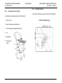
NOTE: Presence of a bar is binary 1, and the absence of a bar is binary 0.
A.9d Line Read Setup 2
(“Setup” > “Line Read” > “Setup 2”)
The GRM mark must be located in the first position. The EOG, PAR, Group
Seq number, and Page Seq number marks may be shifted in the bank of
marks. The Group Seq grouping and the Page Seq grouping must be located
as sets, however.
Probes A/B
Select the reading probe to be used.
Bit Weight
Page and Group marks can be arranged as Most Significant Bit First (MSB) or
Most Significant Bit Last.
MSB First is the first bit encountered when reading.
MSB Last is the last bit encountered when reading
Lines / Inch
The code marks can be at 1/6, 1/8, or 1/10 inch spacing. This is 6, 8, or 10
lines per inch. There can be as many as 25 mark locations in a bank.
EXAMPLE
GRM
EOG
GS1
GS2
GS4
GS8
PS1
PS2
PS4
PAR
Example MSB Last
GRM
EOG
GS1
GS2
GS4
GS8
PS1
PS2
PS4
PAR
Example MSB First
GRM
EOG
GS8
GS4
GS2
GS1
PS4
PS2
PS1
PAR
Gate Mark
End of Group
Group Seq Bit 1
Group Sea Bit 2
Group Seq Bit 4
Group Seq Bit 8
Page Seq Bit 1
Page Seq Bit 2
Page Seq Bit 4
Parity
438 V4 OPERATOR & SERVICE MANUAL
071-28558-401
ISSUE 2008/05
INTRODUCTION
SECTION A – PAGE 36
GBR Line Code Calibration
Calibration Procedure
NOTE: Calibration is normally to be used by the service technician only.
See section “GBR Line Code Read” for related information. See Line
Read Setup 0, “Line Calib” for B+H Line Read calibration.
The GBR Line Code Recognition system can be calibrated to the particular
machine in which it is installed. Calibrating the Line Code Recognition system
to the particular machine eliminates parts tolerance problems and provides a
method of recalibration once parts have become worn.
Calibration of the machine is provided for 1/10”, 1/8" and 1/6" code spacing.
There is a different calibration number stored in battery backed memory for
each type of code spacing. This means a machine must be calibrated when
the proper line code spacing is selected. Once a machine has been
calibrated for 1/6", 1/8", or 1/10” spaced codes it will operate properly until
the parts on the machine become severely worn.
The machine is calibrated by running a special Calibration sheet through the
machine. The Calibration document has two precisely placed marks on the
document. These marks provide the needed reference points to calibrate the
machine. The same sheet is used for all three settings.
Description of A Calibration Document
A Calibration document has two precisely placed Line Code marks on a
document. The first Line Code mark is placed one inch from the leading edge
of the document. The second Line Code mark needs to be precisely placed 6
inches away from the first Line Code mark. No other marks can be in the area
between the two marks. This will give the Line Code Recognition system the
expected reference distance to calibrate to the machine. The Line Code
Recognition card uses the two marks on the Calibration document to count the
number of encoder signals that occur between the marks. If the number of
encoder signals counted are within 15 % of the expected number of encoder
signals, it is considered a valid calibration value.
438 V4 OPERATOR & SERVICE MANUAL
071-28558-401
ISSUE 2008/05
FOR 1/10”, 1/8" AND 1/6" SPACED LINE CODES
1) Check all mechanical setups in the machine. Examples:
Friction feeder is free of mechanical binding
Singulator is adjusted properly
Documents are processed through machine without distorting the
paper
All paper hold downs are set up properly
Paper rails are set to the proper width
2) Line Read Setup 4 and all preceding Setup 2 must be performed first.
3) Select “Calibration On”.
4) Press “OK”.
5) Now feed a single Calibration document on the machine.
6) If none of the following errors are declared when a calibration document
is fed the Line Code Recognition system is calibrated for the current
selected Line Code spacing.
Errors Indicating A Bad Calibration
NO FEED
NO GATE MARK DETECTED
NO GATE MARK DETECTED IN 2ND BANK
CALIBRATION OUT OF RANGE
7) If a bad calibration is indicated RECALIBRATE must be selected before
another Calibration document is fed. (Go back to step 4.)
INTRODUCTION
SECTION A – PAGE 37
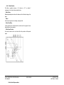
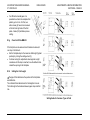
Tolerance
Use LOW setting unless there is not a good contrast between the document
background and the function marks. The LOW setting will tolerate some drift in
the printer registration. Use of the HIGH setting does not allow drift in the
printer registration. The mark location is very critical if the HIGH setting is used.
Use it if the contrast between the document and the function marks is poor.
The Line Code Recognition system supports two print line windowing schemes
when interpreting a Line Code. The two windowing schemes are High
tolerance and Low tolerance reading. Having two windowing schemes permits
service personnel to select the windowing scheme which is best suited for the
customer’s application.
When Low Tolerance read is selected the print line windowing scheme used
does not detect paper slippage. This means the integrity of the Line Code
information must be ensured by the data fields represented within the code.
A Low Tolerance interpretation of a line code synchronizes the print line
windows on the Gate Mark. The Print lines following the Gate Mark are divided
into absolute locations. When a mark is detected it is automatically associated
with a Print line number. This means the Line Code Recognition system will not
look for the standard tolerances applied between Line Code marks.
When High Tolerance read is selected the print line windowing scheme applies
the standard tolerance specification between Line Code marks. This makes it
likely for paper slippage in the machine to be detected during the interpretation
of the Line Code. Detecting paper slippage improves the integrity of the Line
Code Recognition process. It also introduces the possibility of more reading
errors being created.
A High Tolerance interpretation of a line code synchronizes the print line
windows on the Gate Mark. The Print lines following the Gate Mark are divided
into zones of 1/2 print lines. Centered around the expected location of every
Line Code Mark is a 1/2 print line zone where the Line Code mark is expected
to be detected. Between two Line Code marks there is a 1/2 print line zone
where a mark can not be detected without creating an error. This ensures that
all Line Code marks are exactly where they are expected.
Press “OK”
438 V4 OPERATOR & SERVICE MANUAL
071-28558-401
ISSUE 2008/05
INTRODUCTION
SECTION A – PAGE 38
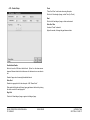
A.9e Line Read Setup 3
Usage - It is interpreted as a binary number. This number must be constant
for all the pages within a package. This number should sequentially
( “Setup” > “Line Read” > “Setup 3”)
The reader must be told at what point in a code field it will see page, group,
parity, and inserts. Depending on the code format this indicates when the
field begins, how many lines it consists of, and the maximum value of the
field.
This is crucial to proper reading, and the operator should have a master
code template that shows the location and value of each line in a code field.
If certain fields are omitted, enter an arbitrary number not related to the
specific code in that field.
Example: Where the code is page field first, and there are three lines for the
page field the correct set-up would be Begin: 01 Length: 03 Max value: 7
Group Seq. Mark
Purpose - Identify each page as being a part of an individual package. The
sequential incrementing of the number ensures the document’s printed
sequence is maintained.
increment from package to package (when sequentially counting sheets
upward). This number sequentially counts from 0 to 15.
Page Seq Mark
Purpose - Identify each individual page within a package. The sequential
incrementing of the number ensures the documents are assembled in the
proper order.
Usage - It is interpreted as a binary number. This number sequentially
counts from one to as high as seven.
Inserts Mark The length will coincide with the number of stations on
the inserter, e.g. six stations = a length of six lines with each line
representing a station. If the code shows a mark at one of the
positions the corresponding station will feed an insert.
Gate Mark
Location - First OMR mark within a bank (always present)
438 V4 OPERATOR & SERVICE MANUAL
071-28558-401
ISSUE 2008/05
INTRODUCTION
SECTION A – PAGE 39
Purpose - Indicates the start of an OMR code
Usage - synchronizes the OMR system to interpret the remaining OMR
marks in the code.
Total Marks is the number of marks in the current line code block from
gate mark to the end.
EOG At
Purpose - Controls the size of dynamic packages by indicating the end of a
group.
Usage - A solid bar is placed in this location on the page with the largest
page ID number. All other pages within a group should have no mark in this
area.
Not EOG At is used as an added security aid. If Not EOG is checked
the code block must not have a mark in this location except at the end
of the group.
Ink Mark At sets the position in the code block to assign an ink mark
when required
PM Divert At Postage Meter Divert is a signal provided by the
computer when the postage weight of a package exceeds the limit of
the postage meters on the inserter. The signal is delivered at the
Postal Meter Divert Mark
Subset At:
Seq Stop At:
Unseal At:
Parity Mark (not available at this time)
Purpose - Adds parity error checking to the code
Usage - This location is used to maintain an even number of solid marks
within a code.
Note: The fields that are marked Optional can be eliminated by operator
configuration of the machine. However, when a data field is eliminated
package security and integrity suffers.
Subset Mark
Press “OK”
438 V4 OPERATOR & SERVICE MANUAL
071-28558-401
ISSUE 2008/05
INTRODUCTION
SECTION A – PAGE 40
A.9f
Line Read Setup 4
7) Press “BLACK” a second time when the voltage reaches “0” (the
black bar is directly under the light)
8) Remove the paper from under the light and press “TRIP”.
a) Event list will say finished when done.
TRIP POINT #1 value should be between 40 and 150
OFFSET #1 should be between 100 and 250.
If these values are not obtained, go to section A.8b and reset the
probe.
9) Find the average of the recorded OFFSET #1 and #2 values.
10) Change OFFSET #1 and #2 value to this average value by
pressing the + or - keys. (example: OFFSET 1 = 129, OFFSET 2=
111, average =120, set both OFFSET 1 and 2 =120)
11) Change GAIN to 0.
12) Record these settings in the area to the right. In the future this
procedure can be eliminated by entering these values directly.
13) Press “APPLY” to download these parameters to the read system
and then press “OK”.
14) The reader setup is complete. Line Read screens “SETUP 1, 2,
and 3” must be completed before running paper.
(“Setup” > “Line Read” > “Setup 4”)
NOTE: When switching between probes or after the 438 has been switched
off, it may be necessary to repeat this setup procedure.
Note: This screen is used only for B+H Line Read, not used for GBR Line
Read.
1) Turn on the 438, press the SETUP button then press the LINE
READ button.
2) Select “GBR”.
3) Press “OK”.
4) Press “LINE READ” again.
5) Press “SETUP 4”.
a) Take a piece of the stock that is going to be run through the
machine and hand feed it until the light beam is on a white
portion of the paper.
b) Press “WHITE”. The system will indicate that when it is done.
6) Press “BLACK” and slowly move the paper until a black bar is
under the light.
438 V4 OPERATOR & SERVICE MANUAL
071-28558-401
ISSUE 2008/05
NOTE VALUES FOR FUTURE REFERENCE
(To find the values, go to “Setup” > “Line Read” > “Setup 4” and write down
the values listed there)
GAIN: __________
OFFSET #1: __________
OFFSET #2: __________
TRIP POINT #1: __________
TRIP POINT #2: __________
INTRODUCTION
SECTION A – PAGE 41
A.10
LASER BAR CODE READ OPTION
A.10a Laser Safety
The radiation level from the laser does not constitute a health hazard.
Exercise care to avoid any unnecessary, direct exposure to the eyes. Avoid
staring at the light source, since prolonged exposure could result in eye
damage. Avoid deliberate eye exposure to the beam. Inadvertent contact,
however, is not a cause for alarm.
Any service should be performed so as not to violate compliance with the Code
of Federal Regulations, Title 21. Part 1040, Section 10 (21 CFR 1040.10), as
administered by the Center for Devices and Radiological Health, a service of
the Food and Drug Administration under the Department of Health and Human
Services. Do not attempt to defeat any safety provisions.
A.10b Bar Code Basics
A bar code is a group of rectangular bars and spaces arranged in a preset
pattern. The pattern is organized to represent elements of data referred to as
characters. The standard industry codes can represent several alphanumeric
characters.
There are many different types of bar codes. Each type uses its own
symbology, which defines how the bars and spaces represent the letters and
numbers.
The figure below shows each part of a bar code. The labels for each part
remain the same even if the position, orientation, or type of bar code changes.
438 OPERATOR & SERVICE MANUAL
071-28558-401
ISSUE 2008/05
The GBR 438 with the Microscan MS-911 uses the 3 of 9 code or Code 39 fixed or variable length. This was the first code developed that used both
numbers and upper-case letters. It is the most recognized and widely used for
non-retail applications. Each character is represented by a stand-alone group
of 5 bars and 4 spaces. The basic code set includes 0-9, A-Z, * which is used
for the start and stop characters, and six other symbols - . $ / + and % for a
total of 43 characters. Because each of the characters are discrete and selfchecking, Code 39 provides a high level of data security. The Microscan MS911 automatically checks all data for this symbology.
The bar code width must not be printed smaller than 0.010" (.025 mm).
Recommended width is 0.015", code height is 3/8 inch. Minimum quiet zone
start and end of .25 inches.
Bar coding, sizing, tolerance ratio tolerance per ANSI MH10.8-1983. Print
quality must meet or exceed ANSI Grade B per ANSI X3.182, BAR CODE
PRINT QUALITY GUIDELINE.
INTRODUCTION
SECTION A – PAGE 42
A.10c Adjusting Your Microscan MS-911
Your scanner can be mounted in any direction depending on the scheme of
your bar codes. Ladder orientation refers to a bar code whose bars look like a
ladder when facing the bar code’s direction of travel. Picket Fence appear as
a picket fence when facing the direction of travel. Regardless of the direction
of travel, the scan line must be perpendicular to the bars.
In some applications, codes are printed on glossy paper or covered with a
shiny material such as cellophane. When this happens, it is possible that the
code surface reflects so much laser light that it is very difficult for the scan
head to decode the bar code.
To avoid reflections from the surface of glossy bar codes do not mount the
scan head parallel with the object to be scanned. Mount the scan head at a
five to ten degree angle so the laser beam reaches the bar code at a slight
angle.
438 OPERATOR & SERVICE MANUAL
071-28558-401
ISSUE 2008/05
INTRODUCTION
SECTION A – PAGE 43
A.10d Setting the 438 to Read Laser Bar Code
Job
Select the job to run by pressing “ ” or “”.
Note: If your job is not listed, go the next section “Setup 1” to program it in.
Refer to the Appendix in this manual for setup parameters for various jobs. If
your job is not listed call the factory.
Start
This will turn the laser on continuously to hand test the lasers positioning. The
screen will read BAR READ: and an audible beep will sound when the laser
reads the code. The results of the read will be shown on the screen.
Reset Job Defaults
Sets the bar job selected to its defaults, erasing any modifications that may
have been done in the setups.
Press OK to set the job.
“Setup” > “Bar Read”
Modifications to the bar setups are retained as long as the bar job defaults are
not restored or the internal non-volatile storage is not overwritten by a new ‘ini’
file or is lost.
SETUP 1
SETUP 2
SETUP 3
SETUP 4
438 OPERATOR & SERVICE MANUAL
071-28558-401
ISSUE 2008/05
INTRODUCTION
SECTION A – PAGE 44
A.10e Bar Read Setup 1
Group Chg Relates to first page hold
CustId Chg Relates to first page hold
Group Seq
Purpose - Identify each page as being a part of an individual package. The
sequential incrementing of the number ensures the document’s printed
sequence is maintained.
Up – Match in set. Min to Max to Min
Down – Match in set. Max to Min to Max
Matching – Match in set. Must change each set.
Same ID – Match in set. No change needed
None
Min (0 to 1)
Max (0 to 99999)
Max Keypad may be used to set a “Max” value through a keypad instead of
using the arrow scroll button.
Page Seq Purpose - Identify each individual page within a package.
The sequential incrementing of the number ensures the documents are
assembled in the proper order.
Demand Feed
Normal
Mark is on the last page fed. Last page is “1” all others in the pack are “0”.
Reverse
If checked, will handle an inverted Demand Feed sequence. Last page is
“0”, all others in the pack are “1”.
Total Page
Each sheet has a page number and the total number of pages for it’s
group. Select “Total Up” or “Total Down” in Page Sequence.
Read First
The first sheet (Banner Page) of the document is read. The page count
information is used to determine how many more sheets to feed and not
read. After the last non-read sheet is fed, the next fed sheet will be
scanned by the barcode reader to process the next document group.
Page Up - Min to Max within sets.
Page Down - Max to Min within sets.
Roll Up – Min to Max to Min across sets
Roll Down – Max to Min to Max across sets
Total Up - (A-Z) Supports “Total Page” demand feed option.
Total Dn - (Z-A)
None
Min (0 to 1)
Max (0 to 999)
Count Skip
Ink Mark
Mark to drive an ink/zip marking mechanism downstream.
Meter Divert
Mark to drive a divert mechanism downstream.
Subset Mark
Unseal Mark
Stitch Mark
BOG Mark Relates to first page hold
438 OPERATOR & SERVICE MANUAL
071-28558-401
ISSUE 2008/05
INTRODUCTION
SECTION A – PAGE 45
Seq Shutdown
Clr last
Stop Last
Clr 1st
Stop 1st
None
Bit Number
Establishes the maximum number of bits in one character. This is
determined by the type of code being used.
Select from 1 through 8:
1-5 3 of 9 Bar Code
6-8 not used at this time
When a package with this bit set is accumulated, the machine stops feeding,
purges the accumulator and transfer conveyor to the inserter, then powers
down.
Bit Direction
Normal
Count bits 5 to 1, left to right, bit position 4 to 0, follow standard bit
position of character.
Reverse
Count bits 1 to 5, left to right, bit position 4 to 0.(B&H)
Normal – A
For multiple character numeric values. For 5 numeric characters
converted to a number, bit positions 16 to 1: 1, 2, 4, 8, 16, 32, 64, 128,
256, 512, 1024, 2048, 4096, 8192, 16384, 32768.
Reverse – A
For multiple character numeric values. For 5 numeric characters
converted to a number, bit positions 1 to 16: 1, 2, 4, 8, 16, 32, 64, 128,
256, 512, 1024, 2048, 4096, 8192, 16384, 32768.
438 OPERATOR & SERVICE MANUAL
071-28558-401
ISSUE 2008/05
INTRODUCTION
SECTION A – PAGE 46
A.10f Bar Read Setup 2
Page Seq Code
Start (0 to 30). Start character.
Length (0 to 3). Number of characters.
Start_Bit (0 to 30). Starting bit position within character.
Length_Bit (0 to 30). Number of bits.
Inserts Code
Start (0 to 30). Start character.
Length (0 to 20). Number of characters.
Start_Bit (0 to 30). Starting bit position within character.
Length_Bit (0 to 30). Number of bits.
Demand Feed Code
Start (0 to 30). Start character.
Length (0 to 20). Number of characters. Used with Normal-A or ReverseA, multiple character numeric values,
Start_Bit (0 to 20). Starting bit position within character.
Ink Mark Code
Start (0 to 30). Start character.
Length (0 to 20). Number of characters. Used with Normal-A or ReverseA, multiple character numeric values,
Start_Bit (0 to 20). Starting bit position within character.
PmDivert Code
Start (0 to 30). Start character.
Length (0 to 20). Number of characters. Used with Normal-A or ReverseA, multiple character numeric values,
Start_Bit (0 to 20). Starting bit position within character.
The software permits a total of 30 characters in Bar Read, however, physically
that isn't always practical due to the length of the code. For instance, 3 of 9
code is physically larger than 128 code (not available on the 438 at this time).
A code in excess of 15 characters becomes problematic with a 3 of 9 code but
a 128 code can easily exceed 20 characters.
Define the position in the barcode string to extract the information for the
following:
Group Seq Code
Start (0 to 30). Start character.
Length (0 to 5). Number of characters.
Start_Bit (0 to 30). Starting bit position within character.
Length_Bit (0 to 30). Number of bits.
IncType – Increment Type
438 OPERATOR & SERVICE MANUAL
071-28558-401
ISSUE 2008/05
A.10g Adjusting the Paper Guide Belts
In order for your laser scanner to read the bar code there can be nothing
blocking its path. The Paper Guide Belts are custom adjustable for your
specific code location.
Place these guide belts to provide as much support evenly across the paper
path as possible without interfering with the lasers view.
INTRODUCTION
SECTION A – PAGE 47
A.10h Bar Read Setup 3
Unseal Code
Start
Start_Bit
Stitch Code
Start
Start_Bit
No Stop Max Errors
Setting “No Stop Max Errors” to “0” allows the machine to function normally
and stop on a read error. Setting to “1” enables the “No Stop” function which,
when a read error is detected, continues to process the job but the pack with
the error is diverted at the end of the inserter. This use of Divert has priority
over “Divert by Mark” and “Divert by Weight”.
To use this function, “Bad Pack Stop Enable” in “Inserter Setup 1” must be
deselected.
Priority Levels for Pm Divert are:
4. “No Stop” if selected in Line Read and Line Read is selected in System
or, if “No Stop” is selected in Bar Read and Bar Read is selected in
System. If “None” is selected for read type then “No Stop” is disabled.
5. “Meter Divert” in Line Read no matter what read type is selected.
6. By “Weight” is default.
Total Page Code
Start (0 to 30). Start character.
Length (0 to 5). Number of characters.
Start_Bit (0 to 30). Starting bit position within character.
Length_Bit (0 to 30). Number of bits.
Sq Stop Code
Start (0 to 30). Start character.
Start_Bit (0 to 20). Starting bit position within character.
Subset Code
Start
Start_bit
438 OPERATOR & SERVICE MANUAL
071-28558-401
ISSUE 2008/05
INTRODUCTION
SECTION A – PAGE 48
Code Lengths:
-1 disables reading in each category, 0 enables reading with variable length
and any number indicates length, e.g. Code 39 with a length of 6 = a code
block with 6 characters.
Code 39 – 3 of 9 Bar Code
I 2 of 5 – Interleaved 2 of 5 Bar Code
Code 128
Number Reads:
Num. Reads – the number of times the reader should scan and take
average to ensure good read. (poor printing can sometimes be a reason
for multiple reads)
A.10i Bar Read Setup 4
ReadFeed Type:
Feed&Read – When it is desired to Feed first and then Read (normal)
Read&Feed – When it is desired to Read before Feed (In cases where the
EOG (end of group) must be known before feeding next page).
Read&Feed:
Start Delay – Only used with Read&Feed, and it is to delay the read to let
the previously fed document get clear of the feeder.
Cust ID Seq:
Same ID – Code group matching between sets.
Matching – Code group matching only within a set.
Off – disables code group matching
Customer ID Code:
Start – Customer number, group ID or other number can be found
beginning with this character in the Bar Code.
Length – Number of lines after the start, i.e. start=6 length=3 (From the
gatemark the start is found at line 6 and the length is line 6, 7 and 8)
438 OPERATOR & SERVICE MANUAL
071-28558-401
ISSUE 2008/05
INTRODUCTION
SECTION A – PAGE 49
A.12
READ ZONE DIAGRAMS
▒
▒
▒
▒
░
438 OPERATOR & SERVICE MANUAL
071-28558-401
ISSUE 2008/05
░
INTRODUCTION
SECTION A – PAGE 50
A.13
POSTAL METERING
GBR 438/420T Postal Meters and Postal Meter Weight Calculation
January 30, 2006- File:g:\iso9000\manuals - operator & service\438ab\service
manual\071-XXXXX-400a (2006-04) service not released\info on postal
metering on 438_420t 7-27-06.doc
Page 51 of 55
Overview
GBR438. If there are two power supplies, care must be taken not to cross
connect them.
General installations use 1 or 2 postal meters and we normally use GBR438
postal meter 2 and 3 leaving postal meter 1, Postal Meter Divert, to be used
as postal meter or a oversize divert station.
The actual order of the meters after the end of the Inserter should be Hi to
Lo weight, PM1, PM2, PM3.
The Postal Meters must be positioned after the last index position of the
Inserter and all meters must be stacked as close as possible together.
Operation
This document outlines the setup of the Postal Meters, Weight Calculation and
Operation of Postal Metering on the GBR 438/420T.
Note: The order of postal meters to weight was reversed at 26412.044 on the
GBR438
GBR 420 and GBR438/420T prior to 26412.044(Aug. 2001):
LOW to High, Postal Meter 1 to Postal Meter 3.
GBR438/420T after 26412.044(Aug. 2001):
HIGH to Low, Postal Meter 1 to Postal Meter 3 to allow Postal Meter 1,
Postal Meter Divert, to divert an over weight/size package first before the
meters.
Note: Revised from the GBR 438 document: n4wght1.doc.
The GBR438 tracks the pack only to the last index position of the inserter.
The GBR438 actually disables the meters which are not to be used leaving
the one meter enabled to meter the pack.
The GBR438 uses the inserter degree encoder to provide “fine timing” by
degrees of the disable/enable signal to the Postal Meters.
The “ON At” degree must come AFTER the Logical Shift (90 Deg.) of the
pack data in the GBR438 inserter software module. The “OFF At” degree
must come BEFORE the next Logical Shift (90 Deg.) of the pack data in the
GBR438 inserter software module. This cycle should occur between 100
and 80 degrees.
Only one pack can traverse the meters at any time.
Installation
The Postal Meter kit uses existing Input/Output(IO) points in the GBR438
and an existing cable kit and normally operates:
Postal Meter Divert(Test point “Postal Meter Divert”, Rack1:Point19) is
Postal Meter 1(PM1).
Select Station 7(Test point “Separation Sol #7”, Rack1:Point4) is Postal
Meter 2(PM2).
Select Station 8(Test point “Separation Sol #8”, Rack1:Point6) is Postal
Meter 3(PM3).
If you use Stations 7 and 8, there are alternate IO points that can be
used, call the factory.
In general the Postal Meters are driven by 24VDC, 3AMP output modules.
24VDC power generally comes from the inserter, but may come from the
438 OPERATOR & SERVICE MANUAL
071-28558-401
ISSUE 2008/05
INTRODUCTION
SECTION A – PAGE 51
Setups
Lineread, Barread Setup:
Postal Meter Divert Enable (Postal Meter 1).
Select Postal Meter Divert Enable “ON”, to operate from a read mark
ONLY.
Select Postal Meter Divert Enable “OFF”, to operate from Weights ONLY.
Inserter Setup:
Postal Meter By Weight Enable
Check ON to enable Postal Meters
Inserter Setup 2:
Postal Meter Divert (Postal Meter 1)
Enter Meter “ON AT:’ in degrees, 0 to 350. After 90 degrees.
Enter Meter “OFF AT:’ in degrees, 0 to 350. Before 90 degrees.
Enter Meter Position ‘STA:
1 to 12 after envelope insert station.
‘0’ to disable this meter.
Enter Point Option ‘PT:’
9 = Postal Meter Divert - DEFAULT
10 = Postal Meter Divert - Inverted Signal
Inserter Setup 3:
Postal Meter 2
Enter Meter “ON AT:’ in degrees, 0 to 350. After 90 degrees.
Enter Meter “OFF AT:’ in degrees, 0 to 350. Before 90 degrees.
Enter Meter Position ‘STA:
1 to 12 after envelope insert station.
‘0’ to disable this meter.
Enter Meter Output Point Option ‘PT:’
1 = Station 7 Select - DEFAULT
2 = Station 8 Select
3 = Inserter E-Stop
4 = Station 1 Error
5 = Station 7 Select - Inverted Signal
6 = Station 8 Select - Inverted Signal
7 = Inserter E-Stop - Inverted Signal
438 OPERATOR & SERVICE MANUAL
071-28558-401
ISSUE 2008/05
8 = Station 1 Error - Inverted Signal
9 = Postal Meter Divert. DO NOT USE.
10 = Inverted Postal Meter Divert. DO NOT USE.
11 = Moistener
12 = Moistener - Inverted
Postal Meter 3
Enter Meter “ON AT:’ in degrees, 0 to 350. After 90 degrees.
Enter Meter “OFF AT:’ in degrees, 0 to 350. Before 90 degrees.
Enter Meter Position ‘STA:
1 to 12 after envelope insert station.
‘0’ to disable this meter.
Enter Meter Output Point Option ‘PT:’
1 = Station 7 Select
2 = Station 8 Select - DEFAULT
3 = Inserter E-Stop
4 = Station 1 Error
5 = Station 7 Select - Inverted Signal
6 = Station 8 Select - Inverted Signal
7 = Inserter E-Stop - Inverted Signal
8 = Station 1 Error - Inverted Signal
9 = Postal Meter Divert. DO NOT USE.
10 = Inverted Postal Meter Divert. DO NOT USE.
11 = Moistener
12 = Moistener - Inverted
Postal Meter Weights
Meter 1 to 2 Weight Value(00000 to 60000)
Meter 2 to 3 Weight Value(00000 to 60000)
Weight Page and Envelope
Enter Page Weight Value(00000 to 60000)
Enter Envelope Weight Value(00000 to 60000)
Weight Inserts 1 2 3 4
Enter Insert >1 Weight Value(00000 to 60000)
Enter Insert >2 Weight Value(00000 to 60000)
Enter Insert >3 Weight Value(00000 to 60000)
Enter Insert >4 Weight Value(00000 to 60000)
INTRODUCTION
SECTION A – PAGE 52
Weight Inserts 5 6 7 8
Enter Insert >5 Weight Value(00000 to 60000)
Enter Insert >6 Weight Value(00000 to 60000)
Enter Insert >7 Weight Value(00000 to 60000)
Enter Insert >8 Weight Value(00000 to 60000)
Weight Calculation
Postal Meter Selection Calculation.
Inserter.
Done when pack is transferred to the
Package Weight = Envelope Weight + (No. Pages * Page Weight) + (Insert1 *
Insert1 Weight)
+ (Insert2 * Insert2 Weight) + . . . through 8 inserts.
If Package Weight is greater than or equal (>=) to Meter 1 to 2 Weight Break
Value
Then Meter 1 operates.
If Package Weight I less than (<) Meter 1 to 2 Weight Break Value and greater
than or equal (>=) to Meter 2 to 3 Weight Break Value
Then Meter 2 operates.
If Package Weight less than (<) Meter 2 to 3 Weight Break Value (and less than
(<) Meter 1 to 2 Weight Break Value)
Then Meter 3 operates.
438 OPERATOR & SERVICE MANUAL
071-28558-401
ISSUE 2008/05
INTRODUCTION
SECTION A – PAGE 53
10. Meter “OFF AT:’ in degrees.
6. Meter Position ‘STA:’ (6 stations after envelope insert station).
2. Enter Point Option ‘PT:’ (2 = Select Station 8)
Postal Meter Weights
30. Meter 1 to 2 Weight Value.
20. Meter 2 to 3 Weight Value.
A.13a Three Meter Example
Meter 1 to 2 Weight Break Value = 30
Meter 2 to 3 Weight Break Value = 20
Package Weight
X
X
X
X
X
X
35
Meter 1
Meter 2
Meter 3
A.13b Two Meter Example
Meter 1 to 2 Weight Break Value = 99.
expected.
Meter 2 to 3 Weight Break Value = 20
X
Three Meter Setup
Lineread Setup:
Select Postal Meter Divert Enable “OFF”, to operate from Weights ONLY.
Inserter Setup:
Postal Meter By Weight: Check ON to enable Postal Meters.
Inserter Setup 2:
Postal Meter Divert(Postal Meter 1)
Meter “ON AT:’ in degrees.
Meter “OFF AT:’ in degrees.
Meter Position ‘STA:’ (6 stations after envelope insert station).
Enter Point Option ‘PT:’ (9 = Postal Meter Divert)
Inserter Setup 3:
Postal Meter 2
Meter “ON AT:’ in degrees.
Meter “OFF AT:’ in degrees.
Meter Position ‘STA:’ (6 stations after envelope insert station).
Enter Point Option ‘PT:’ (1 = Select Station 7)
Postal Meter 3
Meter “ON AT:’ in degrees.
438 OPERATOR & SERVICE MANUAL
071-28558-401
ISSUE 2008/05
Package Weight
6
11
19
20
26
31
Meter 2
Must be greater than any pack
Meter 3
X
X
X
X
X
X
Three Meter Setup
Lineread Setup:
Select Postal Meter Divert Enable “OFF”, to operate from Weights ONLY.
Inserter Setup:
Postal Meter By Weight: Check ON to enable Postal Meters.
Inserter Setup 2:
Postal Meter Divert(Postal Meter 1)
Meter “ON AT:’ in degrees.
Meter “OFF AT:’ in degrees.
Meter Position ‘STA:’ (0 disabled).
9. Enter Point Option ‘PT:’ (9 = Postal Meter Divert)
Inserter Setup 3:
Postal Meter 2
200. Meter “ON AT:’ in degrees.
INTRODUCTION
SECTION A – PAGE 54
10. Meter “OFF AT:’ in degrees.
6. Meter Position ‘STA:’ (6 stations after envelope insert station).
1. Enter Point Option ‘PT:’ (1 = Select Station 7)
Postal Meter 3
240. Meter “ON AT:’ in degrees.
60. Meter “OFF AT:’ in degrees.
6. Meter Position ‘STA:’ (6 stations after envelope insert station).
2. Enter Point Option ‘PT:’ (2 = Select Station 8)
Postal Meter Weights
99. Meter 1 to 2 Weight Value.
20. Meter 2 to 3 Weight Value.
Notes:
Weight Values are 5 digit numbers of arbitrary dimension. Be consistent,
use tens or hundreds of an ounce (or gram) for all values. The maximum
allowable internally computed package (pages + envelope + inserts) total
value is 64000.
The application software (‘GBR420.exe’) is visible and can be copied to and
from an e-mail, another disk or from the hard disk of a computer.
PROCESS:
1. Attached to the New438/426/420T is a new revision ‘GBR420.exe’. Save
this and any other files to your hard disk in a unique folder (such as:
\gbr\29101005\ where 29101 is the part number and 005 is the current
engineering revision number).
2. Make a disk copy of your current master. In Windows Explorer or My
Computer, right click on the 3 ½” Floppy A: and Copy disk…your current
master to a new 3 ½” disk.
3. Copy the new e-mailed software revision executable, GBR420.exe to the
new disk from step 2. Overwrite the previous revision. Copy any other files
sent, such as the dictionary (msgs420.dat) to the appropriate place on the
new disk (such as: \gbr\msgs420.dat). This is the new master for the new
revision.
4. Make a disk copy of this new master to another 3 ½” disk. Use this copy as
the machine boot-disk.
Meter Output Point Option selection locks out standard operation of the
output selected, i.e. ‘Station 7 Select’ selection does not allow standard
Inserter Station 7 select through reading. Choose another Meter Output
Point to resolve conflicts with actual installations.
All meters are positioned at the same Station. This is the station after the
last index track station of the inserter. The number is counted from the
Envelope Insert Station of the inserter.
Factory testing has shown that the pack moves out of the last index track
station between 200 and 350 degrees. Meter enable imprint is timing is
based on the ‘ON AT’ degree for each meter. The first meter in line
tested at 200 degrees. The second meter inline required some delay and
was tested at 240 degrees. At higher speeds, packs imprinted with the
first meter inline were mistakenly being imprinted by the second meter
inline unless its ‘ON AT’ degree was slightly delayed.
A.14
SOFTWARE UPDATES VIA EMAIL
The disk for this product is specifically bootable on the 438. This boot software
is not normally visible and cannot be copied from one disk to another. The
entire disk must be ‘disk copied’ or ‘copy disked’.
438 OPERATOR & SERVICE MANUAL
071-28558-401
ISSUE 2008/05
INTRODUCTION
SECTION A – PAGE 55
SECTION B - PREVENTIVE MAINTENANCE
B.1 Test equipment and tools
1
B.2 General procedures
B2.a
CLEANING THE MACHINE
B2.b
LUBRICATION
1
1
2
B.1
TEST EQUIPMENT AND TOOLS
Fluke Scope Meter
Standard & Metric Hex Wrenches
Small Blade Flat Screwdriver
Philips Head Screwdriver
B.2
B2.a
The 438 should be cleaned daily to remove any dirt or dust that
may interfere with the operation of the machine. Paper dust
collected in motion areas could impede and/or damage integral
parts of the folder. Paper dust can also obscure the read image
reducing a quality read if it accumulates on the read head.
Excess dirt or toner build-up (from laser printing) on the feed
belts could result in damage or marking to the material and/or
premature wear of the feed belts. Therefore, it is important to
perform the following daily cleaning instructions:
1. Clean ALL Feed Belts.
2. Remove ALL Paper Dust by vacuuming using a small clean
paint brush is most effective. Using compressed air to clean the
machine may drive the accumulated dust into hidden areas of
the machine that are not easily accessible resulting in increased
wear and wicking of vital lubricants.
3. Clean the Fold Rollers
4. Clean the Machine Cabinets and Covers.
GENERAL PROCEDURES
WARNING!
DO NOT ATTEMPT TO CLEAN THE 438A WHEN THE
MACHINE IS RUNNING. ATTEMPTING TO DO SO COULD
RESULT IN INJURY. BE SURE THAT MACHINE POWER IS
OFF AT ALL TIMES WHEN CLEANING.
438 OPERATOR & SERVICE MANUAL
071-28558-401
CLEANING THE MACHINE
B2.a1 Cleaning the Fold Rollers
All accumulated paper dust should either be brushed or
vacuumed from the 438. Clean all accumulated paper dust from
the electronic paper sensors.
ISSUE 2008/05
PREVENTIVE MAINTENANCE
SECTION B – PAGE 1
438 OPERATOR & SERVICE MANUAL
071-28558-401
ISSUE 2008/05
B2.a2 Cleaning the Fold Rollers
DO NOT USE ANY LIQUID ON THE FOLD ROLLERS! The fold
plates must be removed in order to clean all fold rollers. Please
use extreme caution when removing the fold plates. They are
heavy and expensive to replace.
B2.a3 Machine Cabinets and Covers
Clean the machine cabinets and covers using a soft damp cloth.
B2.a4 Paper Hopper
The feed belt should be cleaned with a fluid such as isopropyl
alcohol that does not leave a film. Apply some alcohol to a rag
then lightly rub all dirt and film off the belts.
B2.a5 Singulator
The Singulator must be as clean as possible at all times to
insure the proper feeding and singulation of paper by the feed
belt. This may be done first making sure that the singulator is
not worn. If so, loosen the small set screw on the operator side
and rotate the roller to a point where a rounded spot on the
roller will contact the paper.
NOTE: If there flats completely around the roller and no
rounded spot available, the singulator roller should be replaced
as soon as possible.
Once this is accomplished, raise the singulator roller
approximately 3/4" from present setting. Pass an alcohol
dampened rag under the bottom of the singulator roller. Be sure
that it is making sufficient contact to clean away all dirt and
debris from the contact portion of the singulator roller.
PREVENTIVE MAINTENANCE
SECTION B – PAGE 2
B2.b LUBRICATION
No lubrication is required on the 438.
NOTE: If a mechanical component is out of line or deformed, a
small amount of oil may be used as a short term fix (to eliminate
noise or binding) until the component can be replaced.
SECTION C – ELECTRONICS
SECTION C – ELECTRONICS................................................ 1
C.1 LEFT SIDE VIEW, MAIN CABINET ELECTRONICS (CABINET ASS’Y
- 005-28579-501) ......................................................................................................2
C.1 RIGHT SIDE VIEW, MAIN CABINET ELECTRONICS (CABINET
ASS’Y - 005-28579-501) .........................................................................................3
C.2 DC POWER DISTRIBUTION CHASSIS.....................................................4
C.3 E-STOP & INTERLOCK BOARD ASSEMBLY.........................................6
C.4 COMPUTER CHASSIS ASSEMBLY (196-31487-500) ..............................7
C.4a
CPU Controller (SAT-520)....................................................................8
C.4b
Daughter Card........................................................................................8
C.5 AC DISTRIBUTION ASSEMBLY (502-31475-500) ..................................9
C.6 INTERCONNECT BOARD (042-31483-500) .............................................10
C.7 OPTO RACKS – PORT 0, 1 AND 2............................................................11
C.8 SINGLE CHANNEL READ CARD ............................................................12
C.9 LINE CODE READ CHASSIS ....................................................................12
C.9 LINE CODE READ CHASSIS ....................................................................13
C.10 INK MARKER CONTROL BOARD .......................................................15
C.11 CREEPER CONVEYOR MOTOR CONTROLLER..............................16
C.12 FEEDER MOTOR CONTROLLER.........................................................17
C.13 ELECTRONICS SCHEMATICS ..............................................................18
438 OPERATOR & SERVICE MANUAL
071-28558-401
ISSUE 2008/05
ELECTRONICS
SECTION C – PAGE 1
438 OPERATOR & SERVICE MANUAL
ISSUE 2008/05
071-28558-401
C.1 LEFT SIDE VIEW, MAIN CABINET ELECTRONICS (CABINET ASS’Y - 005-28579-501)
ELECTRONICS
SECTION C – PAGE 2
C.1 RIGHT SIDE VIEW, MAIN CABINET ELECTRONICS (CABINET ASS’Y - 005-28579-501)
438 OPERATOR & SERVICE MANUAL
071-28558-401
ISSUE 2008/05
ELECTRONICS
SECTION C – PAGE 3
438 OPERATOR & SERVICE MANUAL
071-28558-401
ISSUE 2008/05
ELECTRONICS
SECTION C – PAGE 4
is separated from the power supplies below by a separate
C.2 DC POWER DISTRIBUTION CHASSIS
(Power Supply Ass’y 044-31500-500)
enclosure.
The 24vdc supply is used to power the input/output modules on
the relay opto racks and to power clutches, brakes and sensors
and E-Stop & interlock circuits.
The +5vdc supply is used to power the reader backplane,
reader encoder, CPU and other digital circuits.
Above is the DC Power Distribution enclosure that contains a
24vdc, a +5, +12 -12vdc power supplies. The E-Stop and
Interlock board is also enclosed at the top of this enclosure and
438 OPERATOR & SERVICE MANUAL
071-28558-401
ISSUE 2008/05
ELECTRONICS
SECTION C – PAGE 5
438 OPERATOR & SERVICE MANUAL
071-28558-401
C.3 E-STOP & INTERLOCK BOARD ASSEMBLY
ISSUE 2008/05
ELECTRONICS
SECTION C – PAGE 6
The two boards shown on this page are connected together to
make one assembly and although these boards can be
separated into two separate assemblies it is recommended that
the board with the relays on it be replaced as a complete
assembly including all relays should it become necessary. The
relays on the board are connected in such a way that it is
difficult to troubleshoot and the assembly is a protection device
to prevent harm to individuals during the machines operation.
The assembly’s location is inside of the top of the DC Power
Distribution Chassis Assembly. (Shown on page 5 of this
manual)
C.4 COMPUTER CHASSIS ASSEMBLY (196-31487-500)
438 OPERATOR & SERVICE MANUAL
071-28558-401
ISSUE 2008/05
ELECTRONICS
SECTION C – PAGE 7
438 OPERATOR & SERVICE MANUAL
071-28558-401
C.4a CPU Controller (SAT-520)
ISSUE 2008/05
Video, I/O, up to 4 Serial Interface (RS232 Ports), two floppy
drive interface, Internet and LPT1 Port.
Description of Ports:
1. Access panel for Line Read
2. BCR Com Ports
3. Not Used
4. Floppy Disk Port
5. Printer Port
6. COM 2 Serial Port
7. Touch Screen Port
8. SVGA Port
C.4b
ELECTRONICS
SECTION C – PAGE 8
Daughter Card
General Description
SAT-520 Daughter Card installed as (2 x 48 I/O (two cards stacked)
or 1 x 96 I/O)
The I/O 96 card is responsible for the Input/Output interface between
the CPU card and external inputs and outputs.
Configuration
Jumpers as shown in diagram
J1 to touch screen
J1 to RS232 connector on cabinet bulkhead
J16 to floppy drive
C.5 AC DISTRIBUTION ASSEMBLY (502-31475-500)
438 OPERATOR & SERVICE MANUAL
071-28558-401
ISSUE 2008/05
ELECTRONICS
SECTION C – PAGE 9
438 OPERATOR & SERVICE MANUAL
071-28558-401
C.6 INTERCONNECT BOARD (042-31483-500)
ISSUE 2008/05
ELECTRONICS
SECTION C – PAGE 10
C.7 OPTO RACKS – PORT 0, 1 AND 2
The opto racks hold the input
and output modules and transfer
their signals to and from the opto
board via ribbon cables plugged
into their respective headers.
The input and output modules
are restrained under a bar that is
fastened with screws to the
boards on both ends and in the
middle. The input modules are
white and the output modules
are red.
The white input
modules come in two flavors, a
regular and a high speed. The
red output modules also come in
two flavors, regular and reed
relay. The high speed white
modules are used for input
pulses that are very short. The
red reed relay output modules
are used in circuits where the
current draw is high, e.g. motors.
It is easy to tell if the module is
working by looking at the
appropriate LED device next to
the module. If it is on it the
module is said to be active.
438 OPERATOR & SERVICE MANUAL
071-28558-401
ISSUE 2008/05
ELECTRONICS
SECTION C – PAGE 11
438 OPERATOR & SERVICE MANUAL
071-28558-401
ISSUE 2008/05
C.8 SINGLE CHANNEL READ CARD
LED 1
LED 2
LED 3
ELECTRONICS
SECTION C – PAGE 12
ON/OFF every second indicating operation (except when
LED 2 is lit)
ON indicates busy: line code read taking place, calibration
read taking place, or machine speed sample being done.
ON indicates line codes will be read using calibration data
that has been stored. OFF indicates line codes will be read
without using calibration data that has been stored.
LED’s 1-4 are all turned on while the boot functions are being
done. All the lights will stay on if a problem is detected in the
hardware of the line code reader card.
LED 5
LED 6
LED 7
LED 8
GBR Part Number (w/GBR Line Code): 042-26908-500
This card is provided only when certain options are included in the
438.
Function:
Interfaces with the Pc104 serially.
Processes signals from the GBR (TJ) or B+H Line Code Cards
Processes Read encoder signals
For B+H Line Read process edge detect and bar detect
LED Indications:
The following LED indications apply only when using B+H line code.
Input of lead edge detection sensor probe 1 (sensing paper
LED off).
Input of lead edge detection sensor probe 2 (sensing paper
LED off).
Not used.
Input of selected line code sensor (Probe 1 or Probe 2).
C.9 LINE CODE READ CHASSIS
438 OPERATOR & SERVICE MANUAL
071-28558-401
ISSUE 2008/05
ELECTRONICS
SECTION C – PAGE 13
438 OPERATOR & SERVICE MANUAL
071-28558-401
ISSUE 2008/05
The previous page contains various photos of the line read chassis
assembly components. The housing is mounted to the top of the
SAT-520 CPU housing. Top right is a picture of the housing with the
cover removed and the read card slid out for a better view. Across
the rear of the housing is a connector soldered into the backplane
which mates with the read card.
In the lower left of the page is a picture of the backplane and the
power connector. The red wire is +5vdc and the next black wire is
5vcom. The yellow wire is +12vdc and the associated black wire is
12vcom. The board is labeled below the connector.
Just to the right and on the lower right of the previous page are
photos of the Read Interface Panel. It is used internal of the read
housing to bring the connections out the front panel of the housing
and connects to the read board inside.
ELECTRONICS
SECTION C – PAGE 14
C.10 INK MARKER CONTROL BOARD
The above is a picture of an Ink Marker Control Board which
permits an operator to control zip code sequencing on an
inserter that supports Ink Marking. When the read code on a
package which has been read by the GBR Feeder is delivered
to the inserter information is passed to the inserter. This
information can include a line or mark which will indicate if the
zip sequence has changed; whether or not the ink marking
device should be activated when the envelope is passed from
the inserter toward the stacking device.
438 OPERATOR & SERVICE MANUAL
071-28558-401
ISSUE 2008/05
ELECTRONICS
SECTION C – PAGE 15
438 OPERATOR & SERVICE MANUAL
071-28558-401
ISSUE 2008/05
C.11 CREEPER CONVEYOR MOTOR CONTROLLER
The V4 Friction Feeder uses a 90vdc motor (shown here in two
pictures) controller to adjust and maintain speeds of the motor
by a set constant voltage output. The creeper conveyor motor
is actuated whenever the paper demand wand has been
lowered and trips the switch in the feed hopper. There are four
connectors that plug into the controller housing, speed control,
enable circuit, ac voltage and motor output.
ELECTRONICS
SECTION C – PAGE 16
C.12 FEEDER MOTOR CONTROLLER
In the above picture, on the left, is the feeder motor controller.
A close-up is on the right. It is a PWM controller and provides
excellent voltage constant over the speed range of the
controller.
438 OPERATOR & SERVICE MANUAL
071-28558-401
ISSUE 2008/05
ELECTRONICS
SECTION C – PAGE 17
438 OPERATOR & SERVICE MANUAL
071-28558-401
C.13 ELECTRONICS SCHEMATICS
ISSUE 2008/05
The following is a list of the requisite schematics for the 438 system.
Drawing #
Description
Page
042-31549-300
042-31350-300
196-30500-300
196-30501-300
196-30502-300
196-30503-300
597-31570-301
597-31570-302
597-31570-303
597-31570-304
597-31570-305
597-31570-305
597-31570-306
597-31570-307
597-31570-308
597-31570-309
597-31570-310
597-31570-311
597-31570-312
597-31570-313
597-31570-314
597-31570-315
597-31570-316
597-31570-317
597-31570-318
597-31570-319
Reader Backplane F30
DC Distribution PCB 438 V4 Elect.
Schematic, Feeder
Schematic Creeper Contl Motor
Schematic, Feeder Motor PCB
Schematic, Controller, Creeper Motor PCB
AC Power Distribution Control Cabinet
AC Power Distribution Chassis 438 V4 Elect.
DC Power Distribution Control Cabinet V4
Elect.
DC Power Distribution Chassis V4 Elect.
E-Stop & Interlock (Sheet 1 of 2)
E-Stop & Interlock (Sheet 2 of 2)
I_O Interconnect, 438 V4 Elect.
I_O Interconnect, Rack Port 0
I_O Interconnect, Rack Port 1
I_O Interconnect, Rack Port 2
I_O Feeder Module 1
Exit Conveyor Module 4 438 V4 Elect.
Keyboard Module 5 438 V4 Elect.
Folder/Accumulator AC Power Distribution
438 V4 Elect.
Folder/Accumulator Control 438 V4 Elect.
Flats Collector Control 438 V4 Elect.
Inserter module 7 438 V4 Elect.
SAT 520 CPU Chassis 438 V4 Elect.
SAT 520 CPU With Touch and Read System
438 V4 Elect
Line Code Read F30 438 V4 Elect.
21
22
23
24
25
26
27
28
29
30
31
32
33
34
35
36
37
38
39
40
41
42
43
44
45
46
Drawing #
ELECTRONICS
SECTION C – PAGE 18
Description
V4 3208 BULK LOADER SCH
V4 CUTTER BULKLOADER MODULES
CABLE 22, 23, 24, 27
V4 INK MARK_KICKER_MOD9_CABLES 17,
19, 32
V4 LINE CODE READ_CP30
V4 MODULE8 CABLE22, 23, 24, 27
Page
438 OPERATOR & SERVICE MANUAL
071-28558-401
ISSUE 2008/05
ELECTRONICS
SECTION C – PAGE 19
438 OPERATOR & SERVICE MANUAL
071-28558-401
ISSUE 2008/05
ELECTRONICS
SECTION C – PAGE 20
438 OPERATOR & SERVICE MANUAL
071-28558-401
ISSUE 2008/05
ELECTRONICS
SECTION C – PAGE 21
438 OPERATOR & SERVICE MANUAL
071-28558-401
ISSUE 2008/05
ELECTRONICS
SECTION C – PAGE 22
438 OPERATOR & SERVICE MANUAL
071-28558-401
ISSUE 2008/05
ELECTRONICS
SECTION C – PAGE 23
438 OPERATOR & SERVICE MANUAL
071-28558-401
ISSUE 2008/05
ELECTRONICS
SECTION C – PAGE 24
438 OPERATOR & SERVICE MANUAL
071-28558-401
ISSUE 2008/05
ELECTRONICS
SECTION C – PAGE 25
438 OPERATOR & SERVICE MANUAL
071-28558-401
ISSUE 2008/05
ELECTRONICS
SECTION C – PAGE 26
438 OPERATOR & SERVICE MANUAL
071-28558-401
ISSUE 2008/05
ELECTRONICS
SECTION C – PAGE 27
438 OPERATOR & SERVICE MANUAL
071-28558-401
ISSUE 2008/05
ELECTRONICS
SECTION C – PAGE 28
438 OPERATOR & SERVICE MANUAL
071-28558-401
ISSUE 2008/05
ELECTRONICS
SECTION C – PAGE 29
438 OPERATOR & SERVICE MANUAL
071-28558-401
ISSUE 2008/05
ELECTRONICS
SECTION C – PAGE 30
438 OPERATOR & SERVICE MANUAL
071-28558-401
ISSUE 2008/05
ELECTRONICS
SECTION C – PAGE 31
438 OPERATOR & SERVICE MANUAL
071-28558-401
ISSUE 2008/05
ELECTRONICS
SECTION C – PAGE 32
438 OPERATOR & SERVICE MANUAL
071-28558-401
ISSUE 2008/05
ELECTRONICS
SECTION C – PAGE 33
438 OPERATOR & SERVICE MANUAL
071-28558-401
ISSUE 2008/05
ELECTRONICS
SECTION C – PAGE 34
view
438 OPERATOR & SERVICE MANUAL
071-28558-401
ISSUE 2008/05
ELECTRONICS
SECTION C – PAGE 35
438 OPERATOR & SERVICE MANUAL
071-28558-401
ISSUE 2008/05
ELECTRONICS
SECTION C – PAGE 36
438 OPERATOR & SERVICE MANUAL
071-28558-401
ISSUE 2008/05
ELECTRONICS
SECTION C – PAGE 37
438 OPERATOR & SERVICE MANUAL
071-28558-401
ISSUE 2008/05
ELECTRONICS
SECTION C – PAGE 38
438 OPERATOR & SERVICE MANUAL
071-28558-401
ISSUE 2008/05
ELECTRONICS
SECTION C – PAGE 39
438 OPERATOR & SERVICE MANUAL
071-28558-401
ISSUE 2008/05
ELECTRONICS
SECTION C – PAGE 40
438 OPERATOR & SERVICE MANUAL
071-28558-401
ISSUE 2008/05
ELECTRONICS
SECTION C – PAGE 41
438 OPERATOR & SERVICE MANUAL
071-28558-401
ISSUE 2008/05
ELECTRONICS
SECTION C – PAGE 42
438 OPERATOR & SERVICE MANUAL
071-28558-401
ISSUE 2008/05
ELECTRONICS
SECTION C – PAGE 43
438 OPERATOR & SERVICE MANUAL
071-28558-401
ISSUE 2008/05
ELECTRONICS
SECTION C – PAGE 44
SECTION D
PROBLEM ANALYSIS
V4 ELECTRONICS
D.1
GENERAL SOLUTIONS TO ERRORS
2
D.2
INITIAL ACTIONS
4
D.3
UNDERSTANDING CARD ID AND SCHEMATICS
Bookmark not defined.
Error!
D.4
D.4a
D.4b
“TEST” SCREEN OPERATION
5
Speed Test .................................................................................... 5
Test Cycle .................................................................................... 5
D.5
D.5a
D.5b
D.5c
IO/144 Board (Inputs and Outputs)
6
Orientation ................................................................................... 6
Locating I/O LED’s and Card Components ................................. 6
I/O Reference Charts.................................................................... 7
D.6
D.6a
D.6b
D.6c
D.6d
D.6e
D.6f
D.6g
D.6h
D.6i
D.6j
ERROR CODES
10
(11xxx) System .......................................................................... 11
(12xxx) Feeder ........................................................................... 12
(13xxx) Accumulator ................................................................. 14
(14xxx) Folder............................................................................ 14
(15xxx) Xfer Conveyor (Xfer Cvyr, Xcvy)................................ 15
(16xxx or 18xxx) Reader ........................................................... 17
(17xxx) Inserter Error Messages ................................................ 26
(19xxx) EngValue Error Messages ............................................ 26
(20xxx) EXITCOMM Error Messages....................................... 26
(21xxx) InFeed Error Messages ................................................. 26
D.7
D.7a
D.7b
ANALYSIS
27
Troubleshooting the GBR Line Code Reader ............................ 27
Physical Specifications of the Line Code System....................... 27
438 OPERATOR & SERVICE MANUAL
071-28558-401
ISSUE 2008/05
PROBLEM ANALYSIS
SECTION D – PAGE 1
438 OPERATOR & SERVICE MANUAL
071-28558-401
D.1
ISSUE 2008/05
GENERAL SOLUTIONS TO ERRORS
Many error codes are the result of jammed paper (physical errors), or
paper expected at specific time and location (read errors: sequence,
blank page, misprinted code, etc.).
The sensors index the number of sheets as they pass, incrementing a
count on the CPU-586. If a corresponding decrement of count does
not occur from the next sensor, a read error is generated. If error
persists, consider failure of sensor or communication problem (poor
connection, etc.).
For many read errors, check that setup parameters are correct before
pursuing functional troubleshooting.
Read errors require a determination of the integrity of the pack. The
operator must look at the readings on the display and manually verify
each sheet.
When read errors occur, it indicates the integrity of the package is in
question. The 438 was not able to verify a page while stream feeding
a package. When the operator is satisfied the package is complete,
press the DUMP key to release the package.
Once a reading error (BLANK or MISREAD) is declared, additional
feeding via the CYCLE key will continue to display BLANK or
MISREAD errors, but will not stop the machine.
PROBLEM ANALYSIS
SECTION D – PAGE 2
Before powering up the 438, the operator must remove any packages
in the accumulator to be sure there will be no initial error conditions.
For electrical type problems, always check the on-off switches as they
are also circuit breakers. There are LED’s on the board that the
Input/Output modules are plugged into that will help isolate many
problems (refer to the I/O 96 Board description in Section D.5).
Solutions to Less Common Errors
A rare, but more difficult-to-find problem can occur with shorts in the
24VDC circuit. Intermittent failure of sensors (5VDC supply) can result
from the 24VDC short. The short will only occur when a 24V
component activates, dropping the 5V supply across the line. The
24V solenoid may be located some distance from the sensor which is
the apparent problem: consider what is supposed to happen before or
when the sensor sees the paper.
If either the Feeder speed or Folder speed are approximately half of
the other, an encoder channel is probably lost. (Check speeds
through Test menu on display.)
Any time a new CPU-586 board is installed, the presets must be
reset, or there will be an error displayed.
If PWB errors occur (errors with PWB as probable source), pull the
board and make sure that all board components are properly seated.
Re-install the board and make sure it is properly seated.
If reader problems are recurring, re-calibrate with the calibration
sheet. Feed the sheet through several times to ensure that the reader
encoder is returning good data. If data is inconsistent, replace the
reader encoder.
An “invalid calibration” error indicates that the calibration reading was
more than 15% different from the expected (stored) result.
438 OPERATOR & SERVICE MANUAL
071-28558-401
ISSUE 2008/05
PROBLEM ANALYSIS
SECTION D – PAGE 3
438 OPERATOR & SERVICE MANUAL
071-28558-401
ISSUE 2008/05
D.2
INITIAL ACTIONS
Ask the operator to describe or demonstrate the problem.
Request all information on the failure. If there is an error
message, refer to the index for guidance to appropriate Repair
Correction Procedures. Some features of the machine may not
be tested during the system checks and therefore, operator
input will be a valuable asset to help diagnose the total system.
If the problem is the result of improper operator action, refer the
operator to the operator documentation or instruct the operator
on the proper actions.
Switch the 438 AC power OFF.
Check all areas of the machine for paper or other obstructions
(including inside the Folder). Remove any paper or obstructions
and feed a sheet through the machine to confirm that alignment
adjustments are correct.
Turn ON the 438, press RESET, then Start/Stop, and confirm
the following:
All drive belts are moving
Sensors are not blocked or fouled
Machine operating parameters set correctly
Document inserted in paper hopper passes through and
is properly folded
NOTE: If physical paper jams re-occur and mechanical
adjustments are correct, escalate service. Potential trouble
spots are numerous but include: worn or damaged parts;
stretched drive belts; excess static.
PROBLEM ANALYSIS
SECTION D – PAGE 4
Verify all cable connections are properly mated, and all
applicable sensor connections (as per application) are mated
properly and not obstructed. In SETUP, verify that correct input
parameters are selected.
Verify the Emergency Stop button is not actuated.
Twist to reset
Press RESET (blue switch)
D.4
“TEST” SCREEN OPERATION
Diagnosis of the system begins with these tests. If it is found
that the displayed information indicates a problem, refer to the
schematics in section D or section F.
D.4b Test Cycle
Press “Test Cycle” for 100 msec On/300 msec Off cycle.
Press “Test Cycle” again to stop test.
The speeds indicated are approximate (inches per second).
NOTE: The FEED and READ speeds must be within 5% of
each other to ensure normal operational condition.
D.4a
Speed Test
Pressing the green “Power On” switch on the keyboard will start
the feeder and folder motors and display the speeds of the
feeder, folder, transfer conveyor, and read encoders.
438 OPERATOR & SERVICE MANUAL
071-28558-401
ISSUE 2008/05
PROBLEM ANALYSIS
SECTION D – PAGE 5
438 OPERATOR & SERVICE MANUAL
071-28558-401
D.5
D.5a
ISSUE 2008/05
IO/96 BOARD (INPUTS AND OUTPUTS)
Orientation
Use this screen to test inputs and outputs:
Press “TEST” and then “IO/144 Board” to enter screen.
Toggle the pointer to the desired input or output using
the “Side” and “Top” information from the next section.
The name of the output or input will be displayed when
the cursor is positioned on its Side and Top Location
block.
Inputs will change state when sensors are blocked or
encoders are rotated.
Use the “Toggle” button to toggle the outputs on and off.
(Interlocks must be closed)
PROBLEM ANALYSIS
SECTION D – PAGE 6
D.5b Locating I/O LED’s and Card Components
Use the IO/96 reference chart in the next section for the screen
and card LED locations. Use the information in the “LED”
column to locate the correct rack, card, and LED on the card.
For further troubleshooting reference the card configuration
number located on the front of each card and on the card itself.
Use this configuration number to locate a representation of the
specific card in the parts section. Each of these parts drawings
includes a number for the schematic that supports that card.
Note:
Some of what you see on the screen is for future use. At this
time the first three rows on the left hand half of the screen
are used for I/O testing. The bottom three rows are set aside
for the future. The same holds true for the right half of the
screen. None of this half is currently being used.
D.5c
I/O Reference Charts
Side (Port)
0
0
0
0
0
0
0
0
0
0
0
0
0
0
0
0
0
0
0
0
0
0
0
0
Top (Point)
00
01
02
03
04
05
06
07
08
09
10
11
12
13
14
15
16
17
18
19
20
21
22
23
Type
Input
Input
Input
Input
Input
Input
Input
Input
Input
Input
Input
Input
Input
Input
Input
Input
Input
Input
Input
Input
Output
Output
Output
Output
Input/Output Description
Feed Sensor
Accumulator Stack Sensor
Feeder Tach
Folder Tach
Demand Signal
Inserter Deg. Encoder
Not Used
Not Used
Start/Stop Switch
Cycle Switch
Dump Switch
Interlock Sense
Exit Conveyor Pkg Presence Sensr
Exit Conveyor Dischrg Sensor
Enc Home Signal
Not Used
Double Detect Sensor
Folder Exit Sensor
Accum Presence Sensor
Cutter Ready
Dump Clutch
Exit Conveyor Clutch
Exit Conveyor Brake
Accumulator Brake
438 OPERATOR & SERVICE MANUAL
071-28558-401
ISSUE 2008/05
PROBLEM ANALYSIS
SECTION D – PAGE 7
438 OPERATOR & SERVICE MANUAL
071-28558-401
Side (Port)
1
1
1
1
1
1
1
1
1
1
1
1
1
1
1
1
1
1
1
1
1
1
1
1
Top (Point)
00
01
02
03
04
05
06
07
08
09
10
11
12
13
14
15
16
17
18
19
20
21
22
23
Type
Output
Output
Output
Output
Output
Output
Output
Output
Output
Output
Output
Output
Output
Output
Output
Output
Output
Output
Output
Output
Input
Input
Input
Input
ISSUE 2008/05
Input/Output Description
Feeder Clutch
Folder Motor Enable
RR Feed Motor Enable
Not Used
Inserter Sol #7
Inserter Sol #1
Inserter Sol #8
Shingle Conv Motor Enable
Inserter Sol #2
Inserter Sol #3
Inserter Sol #4
Inserter Sol #5
Inserter Sol #6
Env Pull or Shuttle
Ink Mark/Kicker
Envelope Flap
Inserter Master Relay
Station 1 Error indicator
(Ext Feeder/Cutter) Dmne-Out
Postal Divert
(Ext Feeder/Cutter) Demand-In
Inserter Run Signal
Cutter Sensor
Station #1 Sensor
PROBLEM ANALYSIS
SECTION D – PAGE 8
Side (Port)
2
2
2
2
2
2
2
2
2
2
2
2
2
2
2
2
2
2
2
2
2
2
2
2
Top (Point)
00
01
02
03
04
05
06
07
08
09
10
11
12
13
14
15
16
17
18
19
20
21
22
23
Type
Output
Output
Output
Input
Output
Input/Output Description
IF42/RA Conv Input Sensor
Not Used
Not Used
Not Used
Not Used
Not Used
Not Used
Not Used
RR IF42/RA Conv Motor Enable
Not Used
Not Used
Not Used
Not Used
Feeder Brake
First Page Hold Brake
First Page Hold Clutch
Ink Mrk/RA Conv Pres Sensor
RR Creeper Motor Enable
Not Used
Not Used
Not Used
Not Used
Not Used
Not Used
438 OPERATOR & SERVICE MANUAL
071-28558-401
ISSUE 2008/05
PROBLEM ANALYSIS
SECTION D – PAGE 9
438 OPERATOR & SERVICE MANUAL
071-28558-401
D.6
ISSUE 2008/05
PROBLEM ANALYSIS
SECTION D – PAGE 10
ERROR CODES
ERROR
EVENT
EVENT CHECK
ERROR ON
CHECK VALUE
ADJUST VALUE
A unique error number. The first two digits specify a machine area or module. The last three define the specific error.
The event or process being monitored.
The mechanism or ‘thing’ used to monitor the event.
The reason an error is flagged.
The value being used to flag the error. Some are calculated based on speed, sheet length, etc.
Where the check value can be adjusted.
ERROR CODE SECTIONS
11xxx // System Messages
12xxx // Feeder Messages
13xxx // Accumulator Messages
14xxx // Folder Messages
15xxx // Xfer Conveyor Messages
16xxx // Barreader Messages
17xxx // Inserter Messages
18xxx // Linereader Messages
19xxx // EngValue Messages
20xxx // COMMPORT3 Messages
21xxx // InFeed Messages
An “8” in the third digit position is the same as a “0”.
Example - “18836” is the same as “18036”.
D.6a
(11xxx) System Errors
Error
11820
Description
“Exit Demand Timeout” (Purpose: Waiting for a Demand from the inserter.)
EVENT: Accumulated Package Ready to Exit Demand.
EVENT CHECK: ExitDemandTimer.
CHECK VALUE: 60 sec.
ADJUST VALUE: Engineering Value 21
Cause: The Time window for Event to occur (60 sec.) had elapsed setting the error.
11821
"Cover Interlock Open or Emergency Stop Set" (See Table at end of section for locations of interlocks)
EVENT: Interlock ON.
EVENT CHECK: Interlock.
CHECK VALUE: -ADJUST VALUE: -ANALYSIS: Interlock ON at power ON.
11822
"Cover Interlock Open or Emergency Stop Set"
EVENT: Interlock ON.
EVENT CHECK: Interlock.
CHECK VALUE: -ADJUST VALUE: -ANALYSIS: Interlock ON at machine powered.
11824
“Exit Sensor Error” (Purpose:
EVENT: Exit Demand.
EVENT CHECK: Exit Demand and Exit Sensor on exit conveyor, Inserter Station 1 Sense.
CHECK VALUE: -ADJUST VALUE: -ANALYSIS: Inserter Station 1 Sensor covered for 6 demands. Sensor blocked
438 OPERATOR & SERVICE MANUAL
071-28558-401
ISSUE 2008/05
REPAIR INFORMATION
SECTION D – PAGE 11
438 OPERATOR & SERVICE MANUAL
071-28558-401
D.6b
ISSUE 2008/05
REPAIR INFORMATION
SECTION D – PAGE 12
(12xxx) Feeder
Error Description
12001 “No Feed Error” (Purpose: make sure a page is fed when the clutch is energized.)
EVENT: Feed Clutch ON, page lead edge to Feed Sensor
EVENT CHECK: NoFeedTimer.
CHECK VALUE: 500 msec.
ADJUST VALUE: -Cause: A page did not feed within the ½ second time window after the clutch was engaged.
12820
“DOUBLE PAGE FED” (Purpose: to stop the feeder when two pages are fed simultaneously.)
EVENT: Under Feed Sensor, Double Detect Sensor.
EVENT CHECK: DoubleDetectCount.
CHECK VALUE: > 2
ADJUST VALUE: -Cause: During a single feed cycle the computer will check the Double Detect Sensor several times. If the sensor reports two pages
during more than one of the computer checks the computer will shut down the feeder and post this error.
12821
“MISSED PAGE” (Purpose: to let the operator know when overlapping pages may have been fed.)
EVENT: Page lead edge to Feed Sensor, next page lead edge to Feed Sensor.
EVENT CHECK: Page lead edge to Feed Sensor.
CHECK VALUE: -ADJUST VALUE: -ANALYSIS:
No page trail edge. Trail edge of previous page not sensed.
This error can be caused by electronic noise generated by the 438 or a connected machine
INITIAL ACTION:
Ground the 438 and the connected machine (i.e. inserter) together
Plug the Open Feed Sensor into the Transfer Conveyor Exit Sensor Plug (if using this option)
If 438 is not in a read mode, go to Setup>> Feeder>>Pulse Feed and make sure “None” is not selected.
12822
“LONG PAGE FED” (Purpose: page being fed stays under the feed sensor too long or the Page Length setup is incorrect.)
EVENT: Feed Clutch ON, page lead edge and trail edge through Feed Sensor.
EVENT CHECK: JamTimer
CHECK VALUE: 150 msec. [(Sheet Length * 150) / Speed]
ADJUST VALUE: -Cause: Time exceeded.
12823
“EXTRA PAGE WAS FED” (Purpose:
EVENT: Page lead edge at Feed Sensor.
EVENT CHECK: Feed Sensor.
CHECK VALUE: -ADJUST VALUE: -Cause: Page lead edge at Feed Sensor. Feed not processing.
12825
“FEED TO ACCUMULATOR JAM (TIME)” (Purpose:
EVENT: Feed Clutch ON, page lead edge and lead edge through Accum. Sensor.
EVENT CHECK: FeedToAccumTimer.
CHECK VALUE: 170 msec. [(CHECK VALUE * 160) / Speed]
ADJUST VALUE: Enginerring Value 24
Cause: Time exceeded.
12826
“SPEED LOW” (Purpose:
EVENT: Feed Encoder Sensor.
EVENT CHECK: Calculate and Average speed.
CHECK VALUE: 25 inches per second
ADJUST VALUE: -ANALYSIS: Speed less than value.
12827
“FEED SENSOR COVERED” (Purpose:
EVENT: Feed Sensor ON.
EVENT CHECK: Check at Feeder Power On.
CHECK VALUE: -ADJUST VALUE: -ANALYSIS: Feed Sensor ON.
438 OPERATOR & SERVICE MANUAL
071-28558-401
ISSUE 2008/05
REPAIR INFORMATION
SECTION D – PAGE 13
438 OPERATOR & SERVICE MANUAL
071-28558-401
D.6c
ISSUE 2008/05
(13xxx) Accumulator
Error Description
13000 “Stack Error” (Purpose:
EVENT: Page passing through Acc. Stack Sensor.
EVENT CHECK: StackTimer.
CHECK VALUE: 500 msec.
ADJUST VALUE: -ANALYSIS: Time exceeded.
13001
“Misfeed Error” (Purpose:
EVENT: Acc. Clutch ON, page passing out of Acc. Presence Sensor.
EVENT CHECK: NoDumpTimer.
CHECK VALUE: 150 msec. [(Sheet Length * 150) / Speed]
ADJUST VALUE: -ANALYSIS: Time exceeded.
D.6d
(14xxx) Folder
Error Description
14001 "Jam In Folder” (Purpose:
EVENT: Accum. Clutch ON to lead edge Folder Exit Sensor.
EVENT CHECK: FolderExitTimer.
CHECK VALUE: 400 msec.
ADJUST VALUE: Engineering Value 4
ANALYSIS: Time exceeded.
14002 “Jam At Folder Exit” (Purpose:
EVENT: Accum. Clutch ON, increment. Lead edge at Folder Exit Sensor, decrement.
EVENT CHECK: PackageCounter.
ERROR ON: > 2.
CHECK VALUE: 2.
ADJUST VALUE: Engineering Value 4
14820 “SPEED LOW” (Purpose:
EVENT: Folder Encoder Sensor.
EVENT CHECK: Calculate and Average speed.
CHECK VALUE: 25 inches per second
ADJUST VALUE: --
REPAIR INFORMATION
SECTION D – PAGE 14
ANALYSIS: Speed less than value.
D.6e
(15xxx) Xfer Conveyor(Xfer Cvyr, Xcvy)
Error Description
15001 “Jam Error”
EVENT: Pack at Xcvy Sta. 1/In Sensor, increment. Pack at Xcvy Out Sensor, decrement.
EVENT CHECK: PackageCounter.
ERROR ON: > 5.
CHECK VALUE: 5.
ADJUST VALUE: Engineering Value 18
15002
15003
“Jam At In Sensor Error”
EVENT: INSERTER. Xcvy. Clutch ON to Pack out of Xcvy Sta. 1/In Sensor.
EVENT CHECK: JamAtInTimer.
CHECK VALUE: 500 msec.
ADJUST VALUE: Engineering Value 23
ANALYSIS: Time exceeded.
“Jam At Out Sensor Error”
EVENT: INSERTER. Xcvy. Clutch ON to Pack into Xcvy Out Sensor.
EVENT CHECK: JamAtOutTimer.
CHECK VALUE: 3000 msec.
ADJUST VALUE: Engineering Value 22
ANALYSIS: Time exceeded.
15002
“Jam At In Sensor Error”
EVENT: HOPPERFILL. Xcvy. Clutch ON to Pack into Xcvy Sta. 1/In Sensor.
EVENT CHECK: JamAtInTimer.
CHECK VALUE: 500 msec.
ADJUST VALUE: Engineering Value 23
ANALYSIS: Time exceeded.
15003
“Jam At Out Sensor Error”
EVENT: HOPPERFILL. Pack into Xcvy Sta. 1/In Sensor to Pack into Xcvy Out Sensor.
EVENT CHECK: JamAtOutTimer.
CHECK VALUE: 3000 msec.
ADJUST VALUE: Engineering Value 22
ANALYSIS: Time exceeded.
438 OPERATOR & SERVICE MANUAL
071-28558-401
ISSUE 2008/05
REPAIR INFORMATION
SECTION D – PAGE 15
438 OPERATOR & SERVICE MANUAL
071-28558-401
ISSUE 2008/05
15004
“?????”
EVENT: HOPPERFILL. Pack into Xcvy Sta. 1/In Sensor to Pack into Xcvy Out Sensor.
EVENT CHECK: JamAtOutTimer.
CHECK VALUE: 3000 msec.
ADJUST VALUE: Engin. Value 22
ANALYSIS: Time exceeded.
15005
“Un-expected Pack Exited Xfer Conveyor” (Purpose:
EVENT: Inserter On-Line, Off-Line, Pack into Xcvy Sta. 1/In Sensor to Pack into Xcvy Out Sensor.
EVENT CHECK: Demand Feed
CHECK VALUE: 100 msec.
ADJUST VALUE: Engineering Value 07
ANALYSIS: Time exceeded.
15006
“Expected Pack Did Not Exit Xfer Cvyr” (Purpose:
EVENT: Inserter On-Line, Off-Line, Pack into Xcvy Sta. 1/In Sensor to Pack into Xcvy Out Sensor.
EVENT CHECK: Demand Feed
CHECK VALUE: 100 msec.
ADJUST VALUE: Engineering Value 07
ANALYSIS: Time exceeded.
15820
"Jam Into Xfer Cnvy Station 1" (Purpose:
EVENT: HOPPERFILL. Xcvy. Clutch ON to Pack into Xcvy Sta. 1/In Sensor.
EVENT CHECK: IntoStation1Timer.
CHECK VALUE: 225 msec. [(CHECK VALUE * 100) / Speed]
ADJUST VALUE: Engineering Value 8
ANALYSIS: Time exceeded.
15821
"Jam Out Of Xfer Cnvy Station 1" (Purpose:
EVENT: HOPPERFILL. Xcvy. Clutch ON to Pack out of Xcvy Sta. 1/In Sensor.
EVENT CHECK: OutOfStation1Timer.
CHECK VALUE: 60 msec. [(CHECK VALUE * 100) / Speed]
ADJUST VALUE: Engineering Value 9
ANALYSIS: Time exceeded.
REPAIR INFORMATION
SECTION D – PAGE 16
D.6f
(16xxx or 18xxx) Reader
(nn=16 Bar Read Messages or nn=18 Line Read Messages)
Error
Description
Cause/Remedy
nn001 "GROUP NUMBER OUT OF SEQUENCE"
The page that was just fed did not follow the selected group sequencing pattern.
-If the group is not out of sequence, check to see that the proper barcode is printed on
the page and that the barcode matches the specifications.
-Check to see that the proper barcode job is selected.
nn002
"EXPECTED END OF GROUP"
438 OPERATOR & SERVICE MANUAL
071-28558-401
If page sequencing down and the last page fed was page 1, the software expects the
next page to have an end of set mark on it (new set and highest page of that set) or if 6
pages are fed into the accumulator, the software expects the next page to have a
subset mark or an end of group mark on it.
-If an end of group mark was present, check to see that the proper barcode is printed on
the page and that the barcode matches the specifications.
-Check to see that the proper barcode job is selected.
ISSUE 2008/05
REPAIR INFORMATION
SECTION D – PAGE 17
438 OPERATOR & SERVICE MANUAL
071-28558-401
ISSUE 2008/05
nn003
"BLANK PAGE"
No code detected.
-Check read setup again, particularly focus.
-Check for correct feed speed.
-Check speed sensor for proper operation.
-Check for failure on the CPU, replace as necessary.
-Bad UARTs.
-Bad software.
nn004
"SHORT GROUP"
-Check the page to determine if error is valid
-Check read setup again, particularly focus.
-Check for correct feed speed.
-Check speed sensor for proper operation.
-Check for failure on the CPU, replace as necessary.
-Bad UARTs.
-Bad software.
nn005
"DUPLICATE PAGE"
-Check read setup again, particularly focus.
-Check for correct feed speed.
-Check speed sensor for proper operation.
-Check for failure on the CPU, replace as necessary.
-Bad UARTs.
-Bad software.
REPAIR INFORMATION
SECTION D – PAGE 18
nn006 "PAGE OUT OF SEQUENCE"
The page that was just fed did not follow the selected page sequencing pattern.
-If the page is not out of sequence, check to see that the proper barcode is printed on
the page and that the barcode matches the specifications.
-Check to see that the proper barcode job is selected.
nn007
Group is not part of set.
-Check to see that the proper barcode is printed on the page and that the barcode
matches the specifications.
-Check to see that the proper barcode job is selected.
-Check read setup again, particularly focus.
-Check for correct feed speed.
-Check speed sensor for proper operation.
"INVALID GROUP"
-Check for failure on the CPU, replace as necessary.
-Bad UARTs.
-Bad software.
438 OPERATOR & SERVICE MANUAL
071-28558-401
ISSUE 2008/05
REPAIR INFORMATION
SECTION D – PAGE 19
438 OPERATOR & SERVICE MANUAL
071-28558-401
ISSUE 2008/05
REPAIR INFORMATION
SECTION D – PAGE 20
nn008
"EXPECTED PAGE ONE"
If page sequencing up, the software expects the first page of each set to be either a 0
or 1 (depending on what minimum page number was selected in the page setup).
-If the page was page 1, check to see that the proper barcode is printed on the page
and that the barcode matches the specifications.
-Check to see that the proper barcode job is selected.
nn009
"GROUP NUMBER OUT OF RANGE"
Group code was not in specified range (i.e. 0-7)
nn010
"PAGE OUT OF RANGE"
Similar to Group Out of Range error (page range must be within 1-7)
nn011 "INVALID!"
Invalid command
-Cycle machine power
nn012
"NOT ENOUGH NV-RAM"
The program has run out of non-volatile ram.
-You should never get this error. If you do get this error, either the software is bad or the
CPU board is bad.
nn013
"PRESETS CORRUPT"
Some of the preset parameters have fallen out of their defined maximum or minimum
range.
-If new EPROMS were just installed this error might occur. If this is the case, ignore the
error.
-If the battery jumper was pulled from the CPU board this error might occur. If this is the
case, install the battery jumper and ignore the error.-If neither of the previous scenarios
happened, the CPU board is probably bad.
nn014
"NV RAM FAILED"
nn015
"DUAL PORT RAM FAILED"
Data in the non-volatile ram was changed.
-Power to the CPU was unplugged directly at the board.
-Noise in the 120 VAC power.
Hardware failure on reader board
-Battery failed or battery jumper missing
-Bad CPU-186 board
nn016
"INVALID COMMAND"
Hardware failure on reader board
-Battery failed or battery jumper missing
-Bad CPU-186 board
nn017
"INVALID PIC INT."
Hardware failure on reader board
-Battery failed or battery jumper missing
-PC 104 CPU Board
438 OPERATOR & SERVICE MANUAL
071-28558-401
ISSUE 2008/05
REPAIR INFORMATION
SECTION D – PAGE 21
438 OPERATOR & SERVICE MANUAL
071-28558-401
ISSUE 2008/05
REPAIR INFORMATION
SECTION D – PAGE 22
nn018
"INVALID SETUP DATA"
nn019
"PARITY ERROR"
Actual lines of codes must match parity setting (odd or even).
-Bad code
nn020
"computed in action" REGISTRATION BAD
OMR Linecode marks are out of tolerance or the spacing is inconsistent
-Bad code
nn021
"BAD ON-CHIP 8501 RAM"
Hardware failure on reader board
-Battery failed or battery jumper missing
-Bad CPU-186 board
nn022
"INVALID READER ERROR"
CPU does not understand reader
nn023
"INVALID CAL. SETUP"
Feed through calibration sheet several times to ensure that encoder is reading properly
(consistent read numbers)
-Reader encoder bad
nn024
"NO BANK 2 GATE MARK"
Reader was expecting two sets of read code, one was missing
-Reader set up improperly
-Code is physically missing
-Check to see that the proper barcode job is selected.
nn025
"computed in action "CALIB_OUT_OF_RANGE” Calibration failed
-Check calibration sheet
-Check read setup again, particularly focus.
-Check for correct feed speed.
-Check speed sensor for proper operation.
"YES NO EOG ARE SAME"
This error is only associated with European machines
-Check read setup again, particularly focus.
-Check for correct feed speed.
-Check speed sensor for proper operation.
-Check for failure on the CPU, replace as necessary.
-Bad UARTs.
-Bad software.
nn026
Reader board memory corrupted
-Restart machine
nn027
"ROLL PAGE OUT OF SEQUENCE"
The page that was just fed did not follow the selected roll sequencing pattern.
-If the roll is not out of sequence, check to see that the proper barcode is printed on the
page and that the barcode matches the specifications.
-Check to see that the proper barcode job is selected.
nn028
"UNEXPECTED RESPONSE"
-Paper jam
-Reader board failed
-Reader encoder bad
nn029
"EXPECTED READING"
nn030
"READER REBOOTED"
-Blank page
-Read encoder failed
-Paper jam
-Feed sensor out of adjustment
-Reader encoder failed
-Bad read board
nn031
"computed in action" “CALIB. IN RANGE”
Calibration was successful
nn032
"NO RANDOM CHECK MK."
-Incorrect document in accumulator
-Random check mark not set correctly in Setup
-Code bad or misprinted
nn033
"UNEXPECTED RANDOM CHECK"
-Incorrect document in accumulator
-Random check mark not set correctly in Setup
-Code bad or misprinted
nn034
"PACK LARGER THAN SET"
There were more sheets in the package than expected.
nn035
"PACK LESS THAN SET"
There were less sheets in the package than expected.
nn036
"GROUP NUMBER CHANGED IN SET"
Every page within a set is supposed to have the same group number and the page that
was just fed did not.
-If the group did not change within the set, check to see that the proper barcode is printed
on the page and that the barcode matches the specifications
-Check to see that the proper barcode job is selected.
nn037
"LAST SET SAME GROUP NUMBER"
The previous group had the same group # as the current.
nn038
"MAX SHEETS IN ACCUM."
The maximum number of sheets set in the system has been reached
-Change setting if a larger pack size is desired
438 OPERATOR & SERVICE MANUAL
071-28558-401
ISSUE 2008/05
REPAIR INFORMATION
SECTION D – PAGE 23
438 OPERATOR & SERVICE MANUAL
071-28558-401
ISSUE 2008/05
-The package size has exceeded the machines capabilities
REPAIR INFORMATION
SECTION D – PAGE 24
nn039
"UNEXPECTED EOG"
The end of group mark was read but not expected.
-The document sequence is out of order.
-Misread.
-Bar code misprinted.
nn040
"NO RESPONSE TIMEOUT"
The reader did not return a reading in the proper amount of time.
-Make sure that the barcode reader is lined up with the code.
-Make sure that the barcode print on the paper is good quality.
nn041
"BAD READ" (bar read)
The bar code reader returned an error.
-Make sure that the barcode reader is lined up with the code.
-Make sure that the barcode print on the paper is good quality.
nn042
"MAX PAGE NOT = NO. PAGES" (bar read)
Incorrect page count in accumulator
-Page count setting incorrect
-EOG mark not seen
-Read error
nn043
"INVALID GROUP NUMBER" (bar read)
-Incorrectly printed document
-Documents out of order
-Code not seen
-Check, clean and adjust scanner
nn044
"BAD CHECK DIGIT" (bar read)
Check digit in code is wrong
-Code not seen
-Check, clean and adjust scanner
nn045
"EXPECTED END OF SET" (bar read)
Documents in package exceeded the max sheets expected
nn046
"EXPECTED PAGE ZERO" (bar read)
Page out of sequence
-Incorrectly printed document
-Documents out of order
-Code not seen
-Check, clean and adjust scanner
438 OPERATOR & SERVICE MANUAL
071-28558-401
ISSUE 2008/05
REPAIR INFORMATION
SECTION D – PAGE 25
438 OPERATOR & SERVICE MANUAL
071-28558-401
D.6g
ISSUE 2008/05
REPAIR INFORMATION
SECTION D – PAGE 26
(17xxx) Inserter Error Messages
Error Description
Currently no error messages for this module.
D.6h
(19xxx) EngValue Error Messages
Error Description
Currently no error messages for this module.
D.6i
(20xxx) EXITCOMM Error Messages
Error Description
20001 “No Message Response”
A message was sent to an exit device (i.e. Inserter), the exit device did not respond.
D.6j
(21xxx) InFeed Error Messages
Error Description
21801 “Paper Demand Timeout”
EVENT: Paper Demand Switch ON to Paper Demand Switch OFF.
EVENT CHECK: PaperDemandTimer.
CHECK VALUE: 20000 msec.
ADJUST VALUE: Engin. Value 17
ANALYSIS: Time exceeded.
21001 “Paper Demand Timeout”
A demand for paper was sent to infeed device (i.e. Feeder), paper was not detected by the feed sensor within the time frame set in
engineering values
D.7
ANALYSIS
Clear area required at the lead edge of the Gate mark 0.332”
D.7a
Troubleshooting the GBR Line Code Reader
Clear area required at the trail edge of the code 0.166”
The pullout rollers (the rollers that are right after the
singulator) should be adjusted such that they evenly grip the
paper as it moves through. Rip off two strips of paper and
place the paper on each side of the pullout rollers. Turn the
rollers by hand and make sure that the two pieces of paper
feed through evenly. If the paper does not feed through
evenly, use the adjustments on the sides of the roller shaft
to adjust the rollers.
Code location on paper
Measured from the leading edge of the form the code should be
placed on the first 1/3 of the form. The Gate mark registration
must be held to +/- 1 print line. (0.125" with 1/8" line spacing)
(0.166" with 1/6" line spacing).
The minimum distance of the Gate Mark from the leading edge
is 0.25”.
D.7b
Physical Specifications of the Line Code System
All other marks should be placed, with respect to the Gate
mark, within a 1/4 of a print line of their expected placement.
The Print Contrast Ratio should be at least 65%
Mark size specifications: Minimum length of solid mark 0.3”
(recommend .5”)
Minimum width of solid mark 0.015” (recommend .020”)
Maximum width of solid mark 0.030”
Clear area specifications: 0.064" when using 1/8" line spacing
and 0.094" when using 1/6" line spacing (minimum clear area
between marks taking into account print registration and
maximum function line size)
Clear area required on each side of marks 0.2”
438 OPERATOR & SERVICE MANUAL
071-28558--401
ISSUE 2008/05
REPAIR INFORMATION
SECTION D – PAGE 27
SECTION E
ADJUSTMENTS AND REPAIR
INFORMATION
E.1
E.1a
FEEDER
2
Description................................................................................... 2
E.1b
Timing Procedures
3
E.1c
Feeder Setup and Adjustments
3
E.2
E.2a
E.2b
E.2c
E.2d
E.2e
E.2f
ACCUMULATOR SECTION
9
Description................................................................................... 9
Accumulator Clutch and Brake Adjustments ............................... 9
Accumulator Dump Roller Replacement.................................... 10
Accumulator Shaft & Bearing Replacement .............................. 11
Infeed Drive Shaft and Bearing Replacement ............................ 12
Dump Shaft and Bearing Replacement....................................... 16
E.3
E.3a
E.3b
E.3c
E.3d
E.3e
E.3f
E.3g
E.3h
E.3i
E.3j
FOLDER
19
Description................................................................................. 19
Fold Principle............................................................................. 19
Components of the Fold Unit ..................................................... 20
Fold Plate Positions.................................................................... 20
Position the Fold Plates and Deflectors...................................... 21
Setting the Fold Length on a MM 438 ....................................... 21
Close Fold Plate MM 438.......................................................... 22
Setting the Fold Length .............................................................. 22
Setting the Fold Roller Gap........................................................ 23
Fine Adjustments and Corrections ............................................. 24
E.4
E.4a
E.4b
E.4c
E.4d
E.4e
E.4f
E.4g
E.4h
TRANSFER CONVEYOR
29
Description................................................................................. 29
Timing........................................................................................ 29
Exit Sensor Test on the Transfer conveyor ................................ 30
438 Configuration of Exit Sensor Module ................................. 30
Package Overhang at Last Station.............................................. 31
Transfer Conveyor's Outfeed Guides Position ........................... 31
Fold Quality ............................................................................... 32
Transfer Conveyor Package Spacing Problem ........................... 32
438 OPERATOR & SERVICE MANUAL
071-XXXXX-400
ISSUE 2008/05
ADJUSTMENTS & REPAIR INFORMATION
SECTION E – PAGE 1
438 OPERATOR & SERVICE MANUAL
071-XXXXX-400
E.1
ISSUE 2008/05
ADJUSTMENTS & REPAIR INFORMATION
SECTION E – PAGE 2
FEEDER
E.1a
Description
A paper hopper (Creeper Conveyor) supplies the bottom fed
friction feeder continuously while the operator loads paper from
the top. It has 4 mounts (2 each side, with set screws) in which
the hopper slides. The creeper conveyor is comprised of two
black rubber belts driven by a motor located on the bottom side
of the hopper. Controlled by a paper level detector, the motor is
activated when the Paper Demand Wand activates the paper
demand switch.
The two stainless steel paper guide rails, mounted on the
hopper, are adjustable via a locking handle at the rear. At the
front they interlock with the Feeder rails, then lock to shafts
running across the machine. Both sets of rails should be
adjusted and aligned together.
A one inch wide timing belt (main feed belt) drives the bottom
sheet of paper under the singulator roller. Two urethane belts
are located to either side of the main feed belt, and assist the
main feed belt, smoothing variations in frictional drive.
A paper demand wand and switch mechanism senses the level
of the paper going into the feeder area. It's job is to regulate the
amount of paper in the feeder area providing the most
productive feeding. A two-inch stationary roller (singulator roller)
rests above the feed belt in the center of the feeder and allows
only the bottom sheet of paper to be fed while holding back all
others.
A series of sensors monitors the flow of paper through the 438
Feeder System. These are known as retro-reflective sensors,
and require no adjustment. Each sensor is aimed at a reflective
tape placed on the other side of a gap through which the paper
travels. The sensor looks constantly at its reflection from the
tape and reports when the reflection disappears (paper
presence). The feed sensor monitors correct feeding and nonfeed of paper while other similar sensors located in the
accumulator section detect stacking and releasing of paper.
Read sensing is accomplished by a Line Code Reader on either
or both the left or right sides of the feeder. By using a reflective
beam to search for code marks a variable electronic signal is
produced and sent to a proprietary electronic read board
interpreting the variations in light intensity.
The double feed detect sensor is an ultrasonic device that will
detect multiple sheets fed from the feeder.
Paper feeding is accomplished when the feed motor drives the
belts. An electric clutch engages the feed belt at a signal from
the controller.
The optical encoder (blue-clad, located on the right side of the
upper pullout shaft) monitors feeder run speed.
E.1B TIMING PROCEDURES
(Not applicable: timing is a function of software and CPU.)
E.1C
Creeper Conveyor Adjustment
FEEDER SETUP AND ADJUSTMENTS
Paper Guide Rails
These rails guide the paper from the hopper table, through the
singulator area and to the accumulator area without skewing.
The guide rails should be set so that with a single sheet of
paper laying flat between them has a 1/16-inch space between
the right and left edges of the sheet and the guide rails. Please
Make certain that the guide rails run parallel with the side frame
of the machine. Loosen the setscrews and the hanger bracket
thumbscrews locking the rail blocks to the cross shafts to adjust
these rails.
The position of the creeper conveyor relative to the feeder is an
important adjustment. To adjust:
a)
Place a sheet of paper in the feed area, up to but not
under the singulator.
b)
Loosen the four set screws of the creeper guide rails.
Once this is accomplished the conveyor will move freely
in and out. Do not pull it all the way out of the clamps: it
will fall!
c)
Bring the hopper table 1/2" away from the back edge of
the sheet of paper.
d)
Tighten the four set screws to clamp the table in this
position.
Whenever document length is changed, this process must be
performed to ensure the proper transfer of paper from the
hopper table to the feeder area.
NOTE: Be sure the side rails are feeding the paper parallel to
the singulating roller.
438 OPERATOR & SERVICE MANUAL
071-XXXXX-400
ISSUE 2008/05
ADJUSTMENTS & REPAIR INFORMATION
SECTION E – PAGE 3
438 OPERATOR & SERVICE MANUAL
071-XXXXX-400
ISSUE 2008/05
Paper Level Detector
The demand switch (3) monitors the paper through a metal
wand (1). On the top of the wand is a spring-loaded, hex head
adjustment bolt which, when turned, raises and lowers the
wand.
Raise the wand to allow more paper to be fed into the
feeder.
Lower the wand to reduce the amount of paper
ADJUSTMENTS & REPAIR INFORMATION
SECTION E – PAGE 4
Setting Main Feed Belt Tension
The feed belt provides the primary force separating a sheet
from the bottom of the shingled stack. The setup procedure for
this belt is described below. The feed belt tension adjustment
knob is factory set, limited to approximately 3/4 turn. This is
adequate operator adjustment for typical paper weight
variations. If the Feed Belt is replaced:
1.
2.
3.
4.
5.
Loosen the long set screw (3/32") on the top stop collar
of the feed belt tension knob shaft.
Lay a straight edge across the top of the feed belt
(lengthwise). Make sure it lays across both pulleys.
Adjust the feed belt tension knob so 3/16 inch feed belt
deflection is possible in the middle of the belt.
Now turn the tension knob 3/8 turn CCW.
Slide the stop collar to the top of the tension knob shaft.
Position collar so the long set screw is perpendicular to
the side frame. Tighten set screw to the tension knob
shaft. This will again limit adjustment to 3/4 turn.
Singulator and Paper Demand
Belt Adjustment Figure
Singulating Roller
The singulating roller creates a precise singulating gap. There
are three critical adjustments required to get a precise
singulating gap. These adjustments are:
• Vertical position of singulating roller
• Singulating roller parallel with lower rollers
• Occasional rotation of singulating roller
NOTE: Proper singulator adjustment depends on paper
variables such as stock, finish and environmental factors.
Specific adjustment on every job will be different. Adjust
the singulator roller as paper is feeding to get best setting.
Position of Singulating Roller
The position of the Singulating Roller with respect to the two
rollers on the lower shaft is critical. This spacing creates the
singulating gateway. The setup process is as follows:
1.
Place one sheet of paper under the singulator.
2.
Lower the singulating roller so the sheet can not pass
under the roller. (Use chrome knurled knob.)
3.
Slowly raise the singulating roller by rotating the chrome
knob clockwise
4.
Attempt to pull the document out while slowly raising the
singulating roller.
5.
When the document starts to move, as you firmly pull it
under the singulating roller, proper singulation
adjustment is achieved.
6.
Load the feeder area with paper and make a test run.
7
If more than one sheet is fed, lower the singulator two
knob clicks. If, after adjusting as many as five knob clicks
proper feeding is not obtained, then all of the setup
procedures for the singulator should be reviewed.
438 OPERATOR & SERVICE MANUAL
071-XXXXX-400
ISSUE 2008/05
ADJUSTMENTS & REPAIR INFORMATION
SECTION E – PAGE 5
438 OPERATOR & SERVICE MANUAL
071-XXXXX-400
ISSUE 2008/05
Set Singulating Roller Parallel to Lower Rollers
The gap between by the singulating roller and the two lower
rollers must be equal for both of the rollers. The procedure for
testing and making the adjustment is described below.
Note: This adjustment is normally done only when a new
singulating roller is installed. It is not necessary to adjust it
on a regular basis.
1.
2.
3.
4.
5.
6.
7.
8.
Cut two strips of paper from the same document
(approximately 1/2" x 8").
Put them between the two lower rollers and the large
Singulating Roller.
Adjust singulating roller until light tension is felt on the
paper between the rollers.
Check that the tension on both strips of paper is the
same. If it is not the same, then adjust the geometry of
the singulating roller.
Loosen the 10-32 x 5/8” socket head cap screws (4) on
the side rail or the back of the singulator plate. Adjust
either to best advantage.
Carefully position the singulator, using the small amount
of play available, to raise the side of the singulator that
has the most tension.
Tighten the 10-32 x 5/8” socket head cap screws
loosened in step 5.
Retest the tension of the two strips of paper by returning
to step 3.
ADJUSTMENTS & REPAIR INFORMATION
SECTION E – PAGE 6
Rotating Singulating Roller
The singulating roller is the place where the highest frictional
forces are created. These frictional forces wear down the
singulating roller. This requires that the singulating roller be
rotated approximately every 250,000 sheets fed, depending on
paper type and operator’s adjustment of the singulator.
1.
2.
3.
Raise the singulating roller above the feed rollers and
feed belt until there is a gap.
On the left hand side of the singulating roller use a 5/64"
allen wrench to loosen the set screw which keeps the
singulating roller from rotating.
Rotate the singulating roller to expose a new wear
surface (rotate about 1/4 inch). The worn surface should
be rotated forward. This will prevent the worn surface
from coming in contact with paper that is being fed into
the singulation point.
Auxiliary Feed Belt Adjustment
The auxiliary feed belts are adjustable by angling the back end
up or down.
Turn the knob clockwise to lower the rear end of the
auxiliary drive belts
Turn the knob counterclockwise to raise the rear end of
the belts.
The ideal setting for the auxiliary belts is when the upstream
end is raised just above the main feed belt.
The auxiliary feed belts assist the main feed belt when
variations in frictional characteristics are encountered and the
feeding of paper becomes erratic. The auxiliary feed belts would
be adjusted when the gap between the fed sheets needs to be
improved. Raising the auxiliary feed belts will decrease the gap;
lowering the belts will increase the gap.
Feed Belts Figure
438 OPERATOR & SERVICE MANUAL
071-XXXXX-400
ISSUE 2008/05
ADJUSTMENTS & REPAIR INFORMATION
SECTION E – PAGE 7
438 OPERATOR & SERVICE MANUAL
071-XXXXX-400
ISSUE 2008/05
Sensor Adjustments
All of the paper detecting sensors on the 438 are RetroReflective digital sensors. Each sensor has its own amplifier unit
and requires no adjustment.
ADJUSTMENTS & REPAIR INFORMATION
SECTION E – PAGE 8
The picture below shows both the Double Detect and the Feed
Sensor as located in the Feeder section on the GBR Friction
Feeder.
E.2
ACCUMULATOR SECTION
E.2a
Description
Fed by the feeder section, the accumulator is used to group up
to twelve documents before it sends them to the folder. Wedge
shaped stacking ramps position pages sequentially. Stacking
rollers are used to stop the paper and hold it in position. When
released, the stacking rollers drive the collected pages out of
the accumulator.
The Dump Clutch activates the stacking rollers, releasing the
accumulated pages. A stack sensor (marked with an “S”)
detects paper arriving in the accumulator and is positioned just
before the downstream edge of the ramps. The accumulator
sensor (marked with an “A”) indicates presence or absence of a
package in the accumulator and is positioned just downstream
from the back edge of the ramps. It also monitors for successful
package discharge when the dump clutch has been activated.
E.2b Accumulator Clutch and Brake Adjustments
The accumulator clutch is designed with a preset gap; no
adjustments are possible or necessary. There should be a
slight amount of rotational free play in the clutch body to prevent
binding.
ACCUMULATOR CLUTCH & BRAKE SETTING
The accumulator brake does require a gap setting of .005”.
This setting is critical, too tight and the drag on the clutch will
cause premature wearing of the clutch and the brake. Too wide
of a gap and the stacking rollers won’t stop the documents
correctly in the accumulator.
438 OPERATOR & SERVICE MANUAL
071-XXXXX-400
ISSUE 2008/05
ADJUSTMENTS & REPAIR INFORMATION
SECTION E – PAGE 9
438 OPERATOR & SERVICE MANUAL
071-XXXXX-400
E.2c
ISSUE 2008/05
Accumulator Dump Roller Replacement
To replace the dump rollers it is first necessary to disconnect
the accumulator from the folder:
1. Disconnect all electrical connectors to the feeder.
2. Remove the left feeder cover.
ADJUSTMENTS & REPAIR INFORMATION
SECTION E – PAGE 10
8. Remove the green drive belt going from folder to
accumulator.
9. Carefully remove all wire ties for left side folder to
accumulator terminal block wire bundle.
3. Loosen the two thumbscrews that latch the feeder to the
accumulator.
10.Prepare a table to use for supporting the accumulator
whose top is within +/-3” of the bottom of the
accumulator.
4. Loosen the accumulator to feeder drive belt tensioner
and remove belt.
11.Remove the two nuts that secure the accumulator to the
folder.
5. Move feeder out of way.
12.Carefully pivot the accumulator onto the table beside the
folder.
6. Remove both accumulator side covers.
7. Remove the lower fold plate sliding cover by first
removing the two stop screws on the slide track.
E.2d
Accumulator Shaft & Bearing Replacement
Removal of Covers
1. Remove power and the lexan accumulator cover. Separate
from feeder section.
2. Remove glide track screws to facilitate removal of bottom
cover.
3. Remove accumulator right side cover by removing bottom
screws. Place hardware in a safe place.
4. Remove knob, by loosening its socket head cap screw, and
left side cover by removing bottom screws. Place hardware
in a safe place.
Screw to be removed
5. Remove end caps on both sides.
for removal of bottom
cover.
Knob to be removed
438 OPERATOR & SERVICE MANUAL
071-XXXXX-400
ISSUE 2008/05
ADJUSTMENTS & REPAIR INFORMATION
SECTION E – PAGE 11
438 OPERATOR & SERVICE MANUAL
071-XXXXX-400
E.2e
ISSUE 2008/05
ADJUSTMENTS & REPAIR INFORMATION
SECTION E – PAGE 12
Infeed Drive Shaft and Bearing Replacement
1. Remove flat green belt by carefully prying up spring tension
idler.
2. Remove the screws on each end of the top shaft by using an
allen wrench in each end and turning in opposite directions.
Infeed Drive Shafts
186-032017499
Screws to be
removed for
removal of shaft
3. Start removing parts: screw, washer, long spacer, flat pulley
and key.
4. Loosen screw for bearing from inside. Slide bearing housing
off. Push bearing out.
5. Loosen round belt pulleys. Remove screws for bearing on
left side.
6. Slide shaft over, removing pulleys one at a time until
complete shaft is out.
7. Loosen screw without marring shaft by holding at timing
pulley.
438 OPERATOR & SERVICE MANUAL
071-XXXXX-400
ISSUE 2008/05
ADJUSTMENTS & REPAIR INFORMATION
SECTION E – PAGE 13
438 OPERATOR & SERVICE MANUAL
071-XXXXX-400
ISSUE 2008/05
8. Remove parts: screw, washer, 2 spacers, pulley, key, small
spacer, bearing housing with clip.
Note: The turned down end is shorter on left side (2 ¾”)
than on right (3 3/16”) (Important for reinstallation).
9. Remove C-clip from bearing housing. Remove bearing and
spacer.
10. Place spacer back in bearing housing. Replace ball bearing
with new 186-031112035 inside bearing housing. Reinstall
C-clip.
11. Slide complete housing onto new top shaft 186-032017499.
Note turned down side. Slide on small spacer (.312”). Install
new key 186-031135001, timing pulley, 2 long spacers,
washer and screw (will be loctited at a later step).
ADJUSTMENTS & REPAIR INFORMATION
SECTION E – PAGE 14
12. Slide shaft back into place with each round green belt and
pulley back into position. Use bottom shaft as a guide.
13. Replace screws for bearing housing on left side (that were
removed in step 5).
14. Replace ball bearing in housing that was removed in step 4
with new ball bearing 186-03112035. Slide onto shaft. Note
location of flat toward infeed end. Mount bearing housing
with the flange to the right side.
15. Tighten down both bearing housings screws.
16. Install new key 186-031135001 into shaft and replace flat
belt pulley and long spacer (that were removed in step 3).
17. Apply blue loctite 188-24205 onto screw threads on both
ends of shaft. Tighten both screws at the same time using
allen wrench at each end.
18. Use a ruler to position round belt pulleys back into place.
19. Reinstall flat green belt (removed in step 1).
20. Spin the shaft to check.
21. Repeat steps 1 – 20 for bottom shaft.
22. If infeed end was the only area that was a problem, replace
all covers and turn on power. If the dump end is a problem,
continue with the following procedure.
438 OPERATOR & SERVICE MANUAL
071-XXXXX-400
ISSUE 2008/05
ADJUSTMENTS & REPAIR INFORMATION
SECTION E – PAGE 15
438 OPERATOR & SERVICE MANUAL
071-XXXXX-400
E.2f
ISSUE 2008/05
Dump Shaft and Bearing Replacement
1. Remove right cover on folder to expose inside folder. Place
hardware in safe place.
2. Remove round green belt.
3. To create space for Accumulator to be pulled off, unplug
green phoenix block and clip ty wraps or if there is a loop of
extra cable only unclip along top.
Loosen nut on both sides. Support Accumulator while removing.
Set on bench near Folder.
ADJUSTMENTS & REPAIR INFORMATION
SECTION E – PAGE 16
4.
5.
6.
7.
Loosen both screws on top dump shaft.
Remove top guide.
Loosen setscrew in spur gear and remove.
Loosen setscrews on round belt pulleys and rollers.
8. Remove timing belt and pulley from top shaft. Note location
of recessed side of pulley. Remove key and spacer.
Remove top
guide.
9. Remove screws for both bearing housings from inside.
10. Slide shaft out.
11. Remove spacer (.312”), clip, ball bearing and washer.
12. Reassemble bearing housing with new ball bearing 186031112035.
13. On new top shaft 186-032017833, slide bearing housing,
new key 186-031135001 and spur gear. Tighten setscrew
on spur gear (from step 7).
Remove screw to
loosen tension on
bearing housing plate
Screws to be tighten
with loctite in steps
17 and 27.
438 OPERATOR & SERVICE MANUAL
071-XXXXX-400
ISSUE 2008/05
Large Pivot Point
ADJUSTMENTS & REPAIR INFORMATION
SECTION E – PAGE 17
438 OPERATOR & SERVICE MANUAL
071-XXXXX-400
ISSUE 2008/05
14. Slide top shaft into place and reinstall green belts, rollers
and pulleys using bottom shaft as a guide. Reinstall screws
for bearing housings.
15. Replace new key 186-031135001 on left side and reinstall
spacer, timing pulley with timing belt. Pulley must line up
with key.
16. Apply blue Loctite 188-24205 to top shaft end screws and
tighten simultaneously.
17. Remove screws from bottom shaft.
18. Remove spur gear and spacer from bottom shaft on right
side. See photo at step 7.
19. Remove spring by removing screw. See photo above.
20. Remove left side plate with bearing housing by removing
large screw and washer in right side. Be careful not to lose
pivot point sleeve.
21. Remove right side plate with bearing housing by removing
large pivot point screw. Be careful not to lose pivot point
sleeve.
22. Replace both ball bearings with new ball bearing 186031112035 in both bearing housings.
23. With both plates and bearing removed, Slide new bottom
dump shaft 186-032017834 on by pushing end of old shaft
off and moving pulleys and rollers into place.
24. Reinstall plate and bearing housings with pivot point screw
and spring screw. Tighten hex nut back against chassis.
25. Replace spur gear and spacer.
26. Apply blue Loctite 188-24205 to bottom shaft end screws
and tighten simultaneously.
27. Reset position of round belt pulley and rollers and tighten.
Reinstall top guide.
ADJUSTMENTS & REPAIR INFORMATION
SECTION E – PAGE 18
28. Attach Accumulator back onto Folder. Reinstall all covers.
29. Turn on power.
Pivot Point Sleeve
E.3
FOLDER
E.3a
Description
E.3b Fold Principle
The folder works on the buckle fold principle using a fold plate
and fold rollers.
Refer to the Fold Capacity Chart at the end of this manual.
Fed by the accumulator section, the folder is capable of placing
1 to 8 sheets in a C or Z configuration and up to12 sheets in a V
fold (maximum of 24 panels in any configuration). Adjustable
buckle plates set the distance of the fold from the edge of the
paper. Fold rollers nip the paper as it is buckling, creating the
fold. A 220VAC motor drives all folder shafts and rollers. The
folder speed encoder, located on the infeed roller shaft,
provides a folder speed signal.
Depending on the particular configuration, documents exit the
folder in one of three ways:
1. Shingling conveyor stacker. The stacker allows easy
continuous removal of document(s) while avoiding any loss
of sequence.
2. Buffered transfer conveyor where nest folded documents are
placed in an open station inserter track section.
3. Transfer conveyor where the nest folded documents are
presented to the gripper arm.
Fold rollers 1 and 2 drive the sheet into the #1 fold plate until it
comes up against the adjustable stop. The trailing edge of the
sheet continues to be advanced by the roller and the sheet is
buckled. The sheet is now pinched by fold rollers 2 and 3.
The rollers 2 and 3 pull the folded sheet out of the #1 fold plate
while driving it to the next fold plate.
After the last fold, the sheet is transferred by the delivery rollers
to the delivery belt on a delivery table or into the hopper or open
station of an inserter by means of a transfer conveyor.
Note: The fold rollers are made of polyurethane and steel
sectioned material. Clean using alcohol and a soft cloth.
Fold Roller Diagram Figure
438 OPERATOR & SERVICE MANUAL
071-XXXXX-400
ISSUE 2008/05
ADJUSTMENTS & REPAIR INFORMATION
SECTION E – PAGE 19
438 OPERATOR & SERVICE MANUAL
071-XXXXX-400
ISSUE 2008/05
ADJUSTMENTS & REPAIR INFORMATION
SECTION E – PAGE 20
E.3d
E.3c
Fold Plate Positions
Components of the Fold Unit
In the fold unit 38/4 there are four positions for the fold plates:
Components and operating elements of the fold units:
1. Noise covers
2. Paper thickness measuring device
3. Fold roller gap setting adjustment knobs
4. n/a
5. Handwheel
6. Folder power
switch
Fold Roller Diagram Figure
E.3e
Position the Fold Plates and Deflectors
The Fold plates and deflectors have a hand locking screw (1) each on the left-hand and
right-hand side.
Insert the fold plates and deflectors in such a way that the locking screws (1) fit in the
recesses (2) in the frame of the fold unit.
Secure the fold plates and deflectors by tightening the locking screws.
E.3f
Setting the Fold Length on a MM 438
Loosen the lock screw for the paper stop (3).
Set the stop to the required position on the scale (5) by turning the adjustment wheel (4).
Secure the fold plate stop by tightening the locking screw (3).
By turning the fine adjustment screw (6), the fold length can be fine adjusted with the machine
running.
Adjustment by means of the fine adjustment screw is only possible when the lock screw for the
fold plate stop has been tightened.
By turning the knurled knobs of the adjustment wheel (1), it is possible to make angle
corrections of the paper stop. For example; if the paper is out-of-square.
The combination fold plate of a MM 438 has an infeed section with an adjustable lower lip. This
means the space available to form the buckle can be modified depending on the thickness and
the stiffness of the paper.
The lower lip is moved by turning a fine adjustment screw (2) that is equipped with a scale.
Light paper grades: move the lip forward by turning the screw counter-clockwise.
Heavy paper grades: move the lip backward by turning the screw clockwise.
438 OPERATOR & SERVICE MANUAL
071-XXXXX-400
ISSUE 2008/05
ADJUSTMENTS & REPAIR INFORMATION
SECTION E – PAGE 21
438 OPERATOR & SERVICE MANUAL
071-XXXXX-400
ISSUE 2008/05
ADJUSTMENTS & REPAIR INFORMATION
SECTION E – PAGE 22
For difficult-to-handle paper it is
possible to set back the complete fold
plate by up to 4 mm. For this, two
allen screws (9) have to be loosened
at the left and right side of the fold
plate. A scale (10) facilitates precise
setting.
E.3g
Close Fold Plate MM 438
If the fold plate is not used and must therefore be closed, it
can stay in the fold unit.
Set the fold plate stop to the maximum fold length (highest
position) by turning the setting wheel (1).
Continue turning the adjustment wheel against a slight
resistance until the stop is reached; now the deflector has
closed the opening to the fold plate.
E.3h
Setting the Fold Length
The type of fold determines the position of the fold plates
and deflectors.
The unfolded format determines the fold lengths to be set.
The fold length is the distance between paper stop and fold
line.
Setting Guide for Common Types of Fold
E.3i
Setting the Fold Roller Gap
Each folder is equipped with a paper
thickness caliper (1).
Before setting the fold roller gap,
clamp the respective paper between
the rollers and read the paper
thickness of the scale.
The fold roller gap is set by means of setting screws which are
numbered.
Roller 1
Roller 2
Roller 3
Roller 4
Roller 5
Roller 6
The basic principle of buckle plate folding has to be considered
when choosing the correct setting of the fold rollers.
There are two different types of fold:
Folds with always symmetrical panels.
Folds with partly asymmetrical panels.
is the
infeed roller
st
makes the 1 fold
nd
makes the 2 fold
makes the 3 rd fold
th
makes the 4 fold
is the ejector roller
Folds with always symmetrical panels:
If the panels of a folded sheet always have the same length
when passing through the fold rollers, the gap to be set for the
respective fold roller depends on the number of paper layers
which have left the preceding fold plate.
Folds with partly asymmetrical panels:
If the panels of a folded sheet are of unequal length when
passing through the fold rollers (accordian fold, letter fold in fold
plates 1 and 2), the gap to be set is governed by the number of
paper layers contained on the longer panel.
438 OPERATOR & SERVICE MANUAL
071-XXXXX-400
ISSUE 2008/05
ADJUSTMENTS & REPAIR INFORMATION
SECTION E – PAGE 23
438 OPERATOR & SERVICE MANUAL
071-XXXXX-400
E.3j
ISSUE 2008/05
ADJUSTMENTS & REPAIR INFORMATION
SECTION E – PAGE 24
Fine Adjustments and Corrections
Fold Length
Fold variations may occur if the fold plate stops are not set accurately of if the folding speed is
changed. The fold is off across the whole width of the sheets (as opposed to a skewed fold).
Corrections of the fold length are made by turning the fine adjustment knob (1).
A change in the folding speed also changes the fold length. Therefore the set-up speed must
be maintained.
Skewed Folds
Skewed (out-of-square) folds occur when the paper is not fed at the right angles with respect to
the fold rollers. This can be corrected as follows:
Mark the leading edge of a sheet and feed it through the fold unit (2).
To make the deviation more obvious, exaggerate the skewed fold by hand (3).
Open the folded sheet and place it in front of the roller infeed section (4).
Adjust lower dump rollers on exit end of accumulator through hole indicated.
Out-Of-Square Paper
Shadow Fold (MM 438)
The lower lip can be adjusted by setting knob (5).
If the paper is not cut exactly at right angles, the folded sheet
may show “points”. By turning a setting screw, the fold plate
stop can be made parallel to the
out-of-square paper.
Lower lip advanced:
Small buckle space, setting
knob “-“.
Note: Make this correction only
on the first fold plate.
Correction on Combination Fold Plate MM 438:
It is possible to change the parallelism of the stop by turning the
knurled knob (1).
Loosen the knurled knob
by means of a 4-mm allen
key (2). The angle of the
stop is changed by turning
the two knurled knobs.
The stop is parallel to the
fold rollers when the two
half-round marks (3) face
each other.
438 OPERATOR & SERVICE MANUAL
071-XXXXX-400
Basic position:
“0” is flush with the top of the knob.
Lower lip set back:
Large buckle space, setting
knob “+”.
-
Thin paper grades: Advance lower lip, “-“.
Heavy paper grades: Set back lower lip, “+”.
Accordion Fold
It is possible that heavy paper grades get stuck and form a socalled “accordion fold”. In such a case the fold plates must be
set back.
Loosen the allen screws (6)
both sides of the fold plate.
Set back the fold plate using
the scale (7).
Tighten the allen screws.
Change the fold stop plate by
the same amount.
ISSUE 2008/05
ADJUSTMENTS & REPAIR INFORMATION
SECTION E – PAGE 25
438 OPERATOR & SERVICE MANUAL
071-XXXXX-400
ISSUE 2008/05
ADJUSTMENTS & REPAIR INFORMATION
SECTION E – PAGE 26
Creasing:
An additional scale (2) indicates adjustments of 0.5 mm.
When special types of paper are folded, deviations from the
nominal values may become necessary.
One turn of the setting knob changes the roller gap by 0.5mm.
Individual corrections can be made by means of the numbered
setting knobs at each roller.
The fold rollers and delivery shafts with the matching setting
knobs are arranged according to the following scheme:
Roller 1
Roller 2
Roller 3
Roller 4
Roller 5
Roller 6
is the
infeed roller
st
makes the 1 fold
nd
makes the 2 fold
rd
makes the 3 fold
th
makes the 4 fold
is the ejector roller
The setting knobs are equipped with scales (1). With their
help settings with a precision of 0.1 mm are possible.
To increase the roller gap, turn the setting knob counterclockwise.
When the roller gap is changed by more
than 0.5mm, the values on both scales must
be added.
Example: 0.5 (2) + .16 (1) = 0.66 mm
Standard 438 Folder Knob Setup
438 OPERATOR & SERVICE MANUAL
071-XXXXX-400
ISSUE 2008/05
ADJUSTMENTS & REPAIR INFORMATION
SECTION E – PAGE 27
438 OPERATOR & SERVICE MANUAL
071-XXXXX-400
ISSUE 2008/05
ADJUSTMENTS & REPAIR INFORMATION
SECTION E – PAGE 28
FOLDER JAM
Analysis
When a pack exits the accumulator but isn’t detected by the input sensor in the transfer conveyor (station one), an error is
generated and the machine stops. This prevents damage to the folder. The amount of time allowed is set in Engineering Values
“08 Xcvy Into Station 1 Time”.
This applies to a straight conveyor as well with the exceptions that the exit sensor on the folder is used instead of the transfer
conveyor and the time allowed is set in Eng Values “04 Folder Exit Time”.
A counter feature also keeps track of the number of packs in the folder. When a pack leaves the accumulator, it is incremented
by 1. When a pack reaches the input sensor of the transfer conveyor or the exit sensor of the folder when a straight conveyor is
used, the count is decremented by 1. If this count reaches 3, a folder jam is declared.
Initial Action
Check sensors
Check engineering values (refer to section H, “Engineering Values”)
E.4
TRANSFER CONVEYOR
This timing setup is also used to adjust dwell time for the “Open
Feed” option.
E.4a
Description
The transfer conveyor is an articulated belt system which
presents the nest folded document(s) to the Inserter gripper
arm.
E.4b
Timing
Demand switch on/off timing is critical. The setup of this timing
permits the 438 to achieve optimal handoff to the Inserter.
The demand switch should be made, (contacts closed), when
the gripper arm is approximately perpendicular to the deck of
the Inserter. This point occurs twice each 360 degree cycle of
the inserter. With the gripper arm fully into the insert station the
inserter is said to be at zero or “home” position. During a single
cycle of the inserter the gripper arm, starting in this position, will
move toward the track. When the arm becomes perpendicular
to the deck it is at the first perpendicular point. The gripper arm
continues to move out away from the track and reverses
direction. The inserter is now 180 degrees in its’ cycle. With
the gripper arm continuing to return toward the insert hopper it
will again come to a position perpendicular to the deck. This is
the correct point to have the demand switch send a signal to the
GBR. There is a large window of opportunity here that is about
110 degrees wide. A signal from the demand switch within the
window will tell the GBR it is time to place a package in the
track, and this can be adjusted by rotating the demand block for
optimum performance.
438 OPERATOR & SERVICE MANUAL
071-XXXXX-400
ISSUE 2007/09
Transfer Conveyor Demand Switch Figure
ADJUSTMENTS & REPAIR INFORMATION
SECTION E – PAGE 29
438 OPERATOR & SERVICE MANUAL
071-XXXXX-400
E.4c
ISSUE 2007/09
Exit Sensor Test on the Transfer conveyor
The exit sensor on a 438 creates an interrupt to the control
card. This interrupt permits accurate positioning of packages on
the transfer conveyor. Testing the interrupt communication is
done in the following manner:
ADJUSTMENTS & REPAIR INFORMATION
SECTION E – PAGE 30
E.4d
438 Configuration of Exit Sensor Module
The Exit sensor amplifier module on the transfer conveyor has
an “active state” selection switch on it. This switch can be set to
LIGHT ON or LIGHT OFF. The proper position for the switch is
LIGHT ON.
1. Clear transfer conveyor of all documents
Transfer Conveyor Exit Sensor Figure
2. Place a folded document approximately 1/2 inches before the
Exit sensor on the transfer conveyor.
NOTE: Be sure the inserter is running to supply a demand
signal.
3. Run the 438 and command the machine to dump.
4. The Transfer conveyor will index in response to the dump
command. If the package that was placed just before the
exit sensor stops at the discharge end of the Transfer
conveyor the interrupt is being seen by the control card.
However if the document is passed out of the end of the
transfer conveyor then the interrupt is not being seen by
the control card.
NOTE: See opto 1C3D4: Interrupt signal
E.4e
Package Overhang at insert Station
E.4f
When a package is being presented to the gripper arm (furthest
station from the stuffing station) the package should have only
the trailing edge of the folded document held by the flat green
belts. Positioning the trailing edge of the document at the
centerline of the lower, forward-most shaft provides the desired
document position.
Transfer Conveyor's Outfeed Guides Position
It is recommended that the transfer conveyor arm be positioned
parallel to the deck of the inserter and it should be close enough
to the deck so the outfeed guides do not need to drastically
deflect the folded document. This will help prevent the flat green
belts from creeping and ease the extraction force required to
remove the folded document.
When the gripper arm removes a package from the transfer
conveyor, the flat green belts of the Transfer conveyor will
creep if more than 3/4 of inch of the package is being pinched
by the flat green belts. The creeping of the flat green belts will
cause the packages to become improperly gapped in the
transfer conveyor.
Transfer Conveyor Figure
438 OPERATOR & SERVICE MANUAL
071-XXXXX-400
ISSUE 2007/09
ADJUSTMENTS & REPAIR INFORMATION
SECTION E – PAGE 31
438 OPERATOR & SERVICE MANUAL
071-XXXXX-400
E.4g
ISSUE 2007/09
Fold Quality
Consistent fold size is required to prevent the package size
position from varying too much. It is important that the
packages in the transfer conveyor do not vary so as to throw off
the timing of the ejection.
E.4h Transfer Conveyor Package Spacing Problem
If a package spacing problem occurs in the transfer conveyor, it
should be purged of all the remaining documents in it. This will
reset the package positioning.
ADJUSTMENTS & REPAIR INFORMATION
SECTION E – PAGE 32