1
GO TO TABLE OF CONTENTS
420
Service Manual
ISSUE 12/00
071-25287-400(E)
420 SERVICE MANUAL
071-25287-400(E)
ISSUE 12/00
COVER
-1-
NOTICE
While every care has been taken in the preparation of this manual, no liability will be accepted by GBR Systems Corporation arising out of any inaccuracies or omissions.
All service documentation is supplied to GBR Systems Corporation external customers for informational purposes only. GBR Systems Corporation service documentation is
intended for use by certified, product trained service personnel only. GBR Systems Corporation does not warrant or represent that such documentation is complete. GBR
Systems Corporation does not represent or warrant that it will notify or provide to such customer any future changes to this documentation. Customer’s service of equipment, or
modules, components, or parts of such equipment may void any otherwise applicable GBR Systems Corporation warranties. If Customer services such equipment, modules,
components, or parts thereof, Customer releases GBR Systems Corporation from any and all liability for Customer’s actions, and Customer agrees to indemnify, defend, and
hold GBR Systems Corporation harmless from any third party claims which arise directly or indirectly from such service.
Prepared by:
GBR Systems Corporation
Technical Publications
Copyright 2000 by GBR Systems Corporation. All rights reserved, GBR Systems Corporation..
Copyright protection claimed includes all forms or manner of copyrighted materials and information now allowed by statutory or judicial law or hereinafter granted, including
without limitation, material generated from the software programs which are displayed on the screen such as styles, templates, icons, screen displays, looks, etc.
Printed in the United States of America.
420 SERVICE MANUAL
071-25287-400(E)
ISSUE 12/00
COVER
-2-
USING THE MANUAL
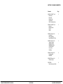
1. TABLE OF CONTENTS
Each capitalized alphabetic character represents a major division within the manual (Section A).
Under each major division, the capital letter is followed by a number. This represents a subdivision of the major section (Section A1. is
a subdivision of A.).
Under each subdivision, an alpha-numeric combination is followed by a decimal and a lower case letter. This represents a smaller
division under a subdivision (Section A1.a. is a subdivision of A1., Section A1.a1. is a subsection of A1.a.).
Each major section of the manual begins with page 1 and is numbered in sequence through that section only. Section A begins with
page 1, section B begins with page 1, etc. There are not necessarily any subdivisions beyond level 1 in a Parts Catalog.
This manual is divided into Section A through I. A detailed table of contents is located on the first page of each section.
SECTION A
INTRODUCTION
Machine Orientation
Machine Specifications
SECTION B
PREVENTATIVE MAINTENANCE
SECTION C
PROBLEM ANALYSIS
Input and Output Test Menu
Speed Test Menu
Setup Test Menu
Cycle Test Menu
Inserter Test Menu
Software Error Codes
Troubleshooting
SECTION D
REPAIR INFORMATION
Repair Checkout Procedures
Feeder Section
GBR Line Code Read (including screen menus and error codes)
Laser Bar Code Read (including screen menus and error codes)
Accumulator Section
Folder Section (includes parts lists)
SECTION E
PRINTED WIRING BOARD INFORMATION
SECTION F
MACHINE SCHEMATICS
SECTION G
INTERFACE TO OPTIONAL EQUIPMENT
Connecting to an Inserter
SECTION H
MISCELLANEOUS
SECTION I
PARTS
420 SERVICE MANUAL
071-25287-400(E)
ISSUE 12/00
COVER
-3-
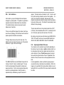
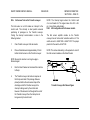
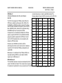
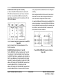
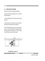
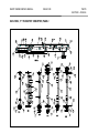
2. HEADERS / FOOTERS
The information listed along the left edge refers to the stated machine. In the following example, the document is the Service Manual
for the BH 6000 machine. TP50429 is an index number which allows Bell and Howell to track its documents.
The particular issue listed in the center is an internal tracking device which allows Bell and Howell to make document revisions. If the
issue is revised, <Rev - #> appears below the issue.
The top line of information along the right side states the title of the particular section. The bottom line lists the section and the page
number within that section.
3. GLOSSARY
A glossary of terms defines and explains all acronyms, abbreviations, and symbols used in the manual.
The glossary lists terms which are cross-referenced to other terms within the manual.
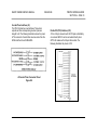
4. TABS
The manual is divided by tabs for easy reference. To find information listed under section B in the table of contents, turn to the tab with
the corresponding title.
Only the major divisions are separated by tabs; i.e., section B is separated from section C with a tab, but section B1 is NOT separated
from section B2 with a tab.
In the back of the manual are 5 blank tab cards. Label these tabs for the subdivisions you frequently refer to and place them
appropriately in the manual.
6. INDEX
The last section of the manual is an alphabetical index which lists the section and page number for each entry.
If an entry is more than one word, search under the alphabetical listing for the primary or most important word(s). If the entry is not
listed under that word, search under the listing of another word in the entry. For example, you need information regarding Envelope
Feeders: First, look under 'Feeder.' If it does not appear there, look under 'Envelope'.
Some entries refer you to other listings. For example, the entry 'Insert Feeders' may refer you to an entry listed as 'Feeder Modules'.
These references are indicated by 'See' or 'See also'.
420 SERVICE MANUAL
071-25287-400(E)
ISSUE 09/00
COVER
-4-
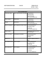
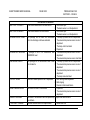
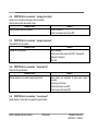
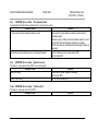
7. LIST OF CHANGES IN THIS REVISION
ECN: 6874
Date: 12/00
Previous release: 420 Service Manual Issue D <Rev. D>
Changes* incorporated in this manual: 420 Service Manual Issue 12/00 <Rev. E>
Section
I
I-9
I-11
I-13
I-15
I-17
I-19
I-21
I-25
I-27
I-29
I-41
I-61
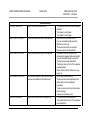
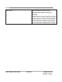
F
Change
add 002K-08066 B & H Line Code Reader
Add 389-26066-400 Ink Marker Option
Add 002K-07970 AC/DC Inserter Control
Add 750-26978-500 3208/Feeder Mechanical Interface
Add 750-27576-500 3208/Feeder Electrical Interface
Add 389-26413-401 Right Angle Interface
Update 002D-08137 Control Panel
change power supply number – item 18
change motor number – item 3, change belt number – item 17
change motor number – item 2, change item 8,23,30
add item 14,15,16
add item 14,15
change item 5 number
change AC Cord number – item 3
change Mount Plate number – item 4, change pulley number – item 17
change Shaft number – item 19
change Gear number – item 22
update T.J. Line Code Read Option
add 002C-07968 Sensor Interconnect Cable
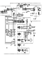
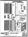
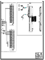
Add 389-26062-300 AC/DC schematic
Added replacement # for 186-2823500088 as 118-30307-600, 8-19-2009
420 SERVICE MANUAL
071-25287-400(E)
ISSUE 09/00
COVER
-5-
Sect A 8/99
Sect B 8/99
Sect C 8/99
Sect D 7/99
Sect E
8/99
Sect F
12/00
Sect G 8/99
Sect H 8/99
Sect I
12/00
420 SERVICE MANUAL
071-25287-400(E)
ISSUE 09/00
COVER
-6-
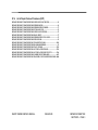
SECTION A - INTRODUCTION
A.1
REQUIRED MANUALS.......................................................................... 2
A.2
Introduction to the manual ...................................................................... 2
A.3
Introduction to the machine..................................................................... 2
A.3a
FEEDER SECTION...........................................................................2
A.3b
ACCUMULATOR SECTION ...........................................................8
A.3c
FOLDER SECTION ........................................................................10
A.3d
POWER UNIT .................................................................................10
A3.e
SENSORS ........................................................................................12
A3.f
EMERGENCY STOP INTERLOCKS ............................................12
A.4
Machine Specification ............................................................................ 15
SMART FEEDER SERVICE MANUAL
071-25287-400
ISSUE 09/00
INTRODUCTION
SECTION A – PAGE 1
SMART FEEDER SERVICE MANUAL
071-25287-400
A.1
ISSUE 09/00
REQUIRED MANUALS
The following manuals are available for the 420:
N/A
N/A
A.2
INTRODUCTION TO THE MANUAL
This manual is intended for service technicians and is organized
to enhance preventive maintenance, troubleshooting, and repair
of the Smart Feeder. Installation of the Smart Feeder is also
described.
A.3
INTRODUCTION TO THE MACHINE
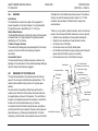
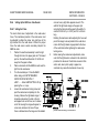
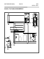
A.3a FEEDER SECTION
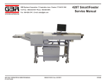
The Smart Feeder’s feeder is bottom fed, top loading for
continuous operation, with a capacity of 1500 sheets (20 lbs).
Creeper Conveyor
The Creeper conveyor comprises two black rubber belts driven
by a motor located on the bottom side of the hopper. Controlled
by a paper level detector, the motor is activated when the
detector indicates that paper is low.
INTRODUCTION
SECTION A – PAGE 2
Hopper and Feeder Paper Guide Rails
The two stainless steel rails mounted on the hopper are
adjustable via a locking handle at the rear. At the front they
interlock with the feeder side rails, then lock to shafts running
across the machine. Both sets of rails should be adjusted
together.
Paper Hopper
The Paper Hopper supplies the bottom fed friction feeder
continuously while the operator loads paper from the top. It has
4 mounts (2 each side, with set screws) in which the hopper
slides. The Hopper Table is located behind the feeder. Paper
level in the hopper is controlled by a demand switch. The
position of the hopper table determines how well the demand
switch will perform this function. During normal operation a
metal wand rests on the incoming paper. As more paper is
needed, the metal wand will fall low enough to close the
demand switch. This activates the creeper conveyor motor to
drive the hopper belts, conveying paper into the feeder area
under the paper level detector. When the proper level of paper
is attained the wand will have been lifted enough to open the
switch, shutting off the creeper conveyor motor.
SMART FEEDER SERVICE MANUAL
071-25287-400
ISSUE 09/00
INTRODUCTION
SECTION A – PAGE 3
SMART FEEDER SERVICE MANUAL
071-25287-400
ISSUE 09/00
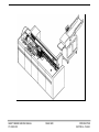
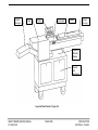
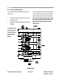
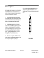
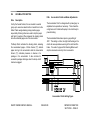
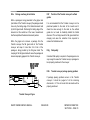
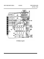
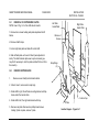
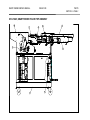
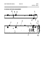
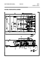
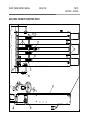
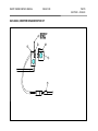
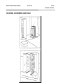
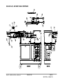
SMART FEEDER and Bell & Howell Inserter - Figure A.1
INTRODUCTION
SECTION A – PAGE 4
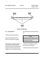
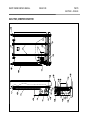
Transfer
Conveyor
Folder
Accumulator
Display
Creeper
Conveyor
Feeder
Optional
Barcode
Reader
Cabinet
with
Electronics
Layout of Smart Feeder - Figure A.2
SMART FEEDER SERVICE MANUAL
071-25287-400
ISSUE 09/00
INTRODUCTION
SECTION A – PAGE 5
SMART FEEDER SERVICE MANUAL
071-25287-400
ISSUE 09/00
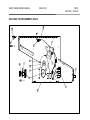
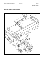
Main Feed Belt
The Main Feed Belt is a one inch wide yellow timing belt which
drives the bottom sheet of paper under the singulator roller.
Also called Singulator Belt.
Auxiliary Feed Belts
These are two red urethane belts located either side of the main
feed belt. The auxiliary feed belts assist the main feed belt,
smoothing variations in frictional drive (correcting erratic feeding
of the paper).
Drive Rollers
These two orange rollers are located directly below the
singulator. These are used in conjunction with the singulator to
ensure only one sheet is fed at a time.
Feeder Section - Figure A.3
INTRODUCTION
SECTION A – PAGE 6
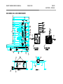
Paper Level Detector
This demand switch monitors the paper going into the feeder
area. It's job is to limit and demand the amount of paper that is
most productive to the feeding process. The Paper Level
Detector monitors the paper through a metal wand.
Singulator
A two inch stationary orange roller which rests above the feed
belt in the center of the feeder and allows only the bottom sheet
of paper to be fed while holding back all others.
Feed Sensor
The Feed Sensor monitors the output of the singulator for
proper singulation or non-feed of paper. It is a light-actuated
through-beam sensor, identified by an “F” on the amplifier.
Double Detect Sensor
Singulator - Figure A.4
The Double Detect Sensor monitors the output of the singulator
for double feeds. It is a light-actuated through-beam sensor,
identified by an “D” on the amplifier.
Feeder Speed Encoder
A blue-clad optical encoder located on the right side of the
upper pullout shaft. It is used to detect feeder run speed.
SMART FEEDER SERVICE MANUAL
071-25287-400
ISSUE 09/00
INTRODUCTION
SECTION A – PAGE 7
SMART FEEDER SERVICE MANUAL
071-25287-400
ISSUE 09/00
Feed Clutch
Electrical clutch which engages the feed belt at a signal from
the controller.
Optical Mark Reader or Read Sensor
Reflective beam sensor located on either the left or right feeder
side rails. A reader logic board interprets variation in light
intensity as it is reflected off the paper and code marks.
A.3b
ACCUMULATOR SECTION
The accumulator is fed paper from the singulator, assembling
groups of one to seven documents. When the document
package is complete, it is fed to the folder.
Stacking Ramps
Stacking Ramps are the plastic wedges which position
successive pages of a document package in order.
Stacking Rollers
These are used to stop the paper and hold it in position. When
released, the Stacking Rollers drive the collected pages out of
the accumulator.
Dump Brake
This prohibits the rollers from releasing paper from the
accumulator.
Dump Clutch
This activates the stacking rollers, releasing the accumulated
pages.
Accumulator Sensor
The Accumulator Sensor indicates presence or absence of a
package in the accumulator. It also monitors package discharge
when the dump clutch has been engaged.
Stack Sensor
Indicates the document has cleared the stacking ramps.
INTRODUCTION
SECTION A – PAGE 8
Accumulator Section - Figure A.4
SMART FEEDER SERVICE MANUAL
071-25287-400
ISSUE 09/00
INTRODUCTION
SECTION A – PAGE 9
SMART FEEDER SERVICE MANUAL
071-25287-400
A.3c
ISSUE 09/00
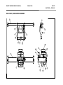
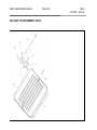
FOLDER SECTION
A.3d
INTRODUCTION
SECTION A – PAGE 10
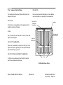
POWER UNIT
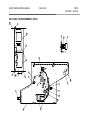
The folder is capable of placing 1 to 4 folds in a C, Z, V, or
double V configuration. It is fed by the Accumulator Section.
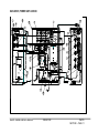
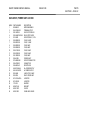
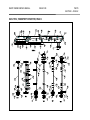
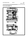
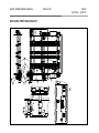
The Power Unit is located inside the cabinet and consists of the
following components:
Buckle Plates
Manual adjustable plates which set the distance of the fold from
the edge of the paper.
Rollers
Used to nip the paper as it is buckling, creating the fold.
Folder Drive Motor
A 110VAC motor which drives all folder shafts and rollers.
Folder Speed Encoder
An encoder, located on the infeed roller shaft, which provides a
folder speed signal.
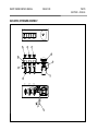
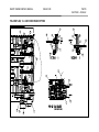
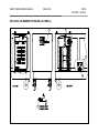
1. Master Relay: Electric safety interlock switch.
2. Fuses: Fuse tips illuminate when the fuse is bad
3. Solid State Relays (SSR): For switching high power items,
motors, etc.
4. 5 VDC Power Supply: logic power.
5. +12VDC and -12VDC power: also logic power
6. +24 VDC Power Supply: power clutches, etc.
Folder Section - Figure A.5a
Power Unit Interior - Figure A-5b
SMART FEEDER SERVICE MANUAL
071-25287-400
ISSUE 09/00
INTRODUCTION
SECTION A – PAGE 11
SMART FEEDER SERVICE MANUAL
071-25287-400
A3.e
ISSUE 09/00
SENSORS
Feed Sensor
The Feed Sensor monitors the output of the singulator for
proper singulation or non-feed of paper. It is a light-actuated
through-beam sensor, identified by an “F” on the top.
Double Detect Sensor
The Double Detect Sensor monitors the output of the singulator
for double feeds. It is a light-actuated through-beam sensor,
identified by an “D” on the top.
Transfer Conveyor Sensors
This monitors the discharge of paper packages from the output
conveyor. It acts to confirm the processing of specific
documents.
Accumulator Sensor
The Accumulator Sensor indicates presence or absence of a
package in the accumulator. It also monitors package discharge
when the dump clutch has been engaged.
INTRODUCTION
SECTION A – PAGE 12
of Module #7 on the I/O Board must be removed. If this E-stop
string is not used this jumper must be in place. Pin 11 of this
connector also provides an "Interlock Sense" signal to an
external device.
There are six (6) safety interlock switches which will interrupt
power to the conveyors and folder whenever a cover is opened:
Under the cover located over the singulator mechanism
Under the cover located over the accumulator section.
On the top cover of the folder.
On the lower cover over the (#2) buckle plate.
On the folder and transfer conveyor meeting point (interrupts
power when the transfer conveyor is removed).
On the clear lexan cover of the transfer conveyor.
Stack Sensor
Accumulator Sensor
A3.f
EMERGENCY STOP INTERLOCKS
The main E-stop located on the operator panel will interrupt
power to the conveyors and folder when pressed down. This
switch must be twisted to bring it back to it's original upper
position.
An extra contact is provided on this E-stop switch which is
routed to pins 30 and 33 of the Inserter Connector located on
the adaptor plate on the end of the cabinet. This will effect an
E-stop to an external device when this contactor is wired to the
E-stop circuit on that external device (e.g. Pinnacle).
A connection to the 420 interlock string has been provided on
pins 28 and 29 of the same Inserter Connector which allows an
external device (e.g. Pinnacle) to E-stop the 420. For this Estop string to be functional a blue jumper across pins 24 and 25
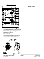
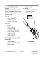
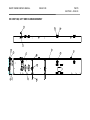
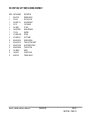
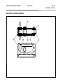
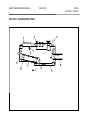
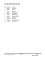
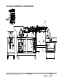
Exit Transfer
Conveyor
TJ Line Code Reader
(placement could be on top
or bottom, left or right)
Feed Sensor
Double Detect Sensor
Paper Demand
Switch/Sensor
Feeder Encoder
Infeed Transfer Conveyor
Folder Encoder
Sensors - Figure A.6
SMART FEEDER SERVICE MANUAL
071-25287-400
ISSUE 09/00
INTRODUCTION
SECTION A – PAGE 13
A.4
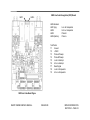
MACHINE SPECIFICATION
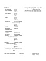
Listed below are specifications for the Smart Feeder:
Throughput
Speed: Max. 24,600 documents per hour
Material
Paper Weights: 20# (75 GSM) Inquire for heavier weights
Paper Size: 7” x 7" (178 mm x 178 mm) to 11” x 14” (305 mm x 356 mm)
Loading Capacity: 2,000 sheets of 20# bond.
Fold Types; "C", "Z", "V" & DOUBLE "V"
Porosity: 20 Gurley seconds
Stiffness: 20 Lb. Stock 170-225 Gurley Stiffness Units
24 Lb. Stock 250-300 Gurley Stiffness Units
Cross Grain Stiffness: 20 Lb. Stock 8~125 Gurley Stiffness Units
24 Lb. Stock 12~150 Stiffness Units
Moisture Content 4-6% by Weight
Components
Feeder: Bottom feed, top loading for continuous operation.
Optical Reader: Optical code reading for group batch recognition, sequencing and double printing control of 1 to 5 document groups.
Larger group batch setting available upon request.
Folder: 4 plates.
Group selector: Manual group selection for 1 to 5 sheets.
SMART FEEDER SERVICE MANUAL
071-25287-400
ISSUE 09/00
INSTALLATION
SECTION A – PAGE 15
SMART FEEDER SERVICE MANUAL
071-25287-400
ISSUE 09/00
INSTALLATION
SECTION A – PAGE 16
Counter Modes: Total count, batch count, resettable count.
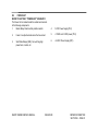
Output Conveyor Options:
Version 1—with shingling output conveyor/stacker
Version 2—with intelligent transfer conveyor interface to gripper arm of inserter's insert station.
Version 3—with a buffering, intelligent transfer conveyor interfaces to an open feed station of inserter The GBR 420-3 can also convert
an intelligent, continuous form mail inserting system to a cut sheet operation.
Controller: Adjustable operator's panel with readout and push-button access to all system functions. System is microprocessor
controlled with self-diagnostics and error display including double, misfeed and jam detection.
Electrical Service
110 Volts, 1 Phase, 60Hz, 9 Amp.
220 Volts, 1 Phase, 50 or 60Hz, 5 Amp.
1,000 BTU/hr
Fuse List - Refer to Section D10
Dimensions
Length: 120" (3048 mm) Model 420-1
Width: 26" (660 mm)
Height: 52” (1321 mm)
Weight: Net approx. 350 Ibs. (159 kg)
Read Options
T.J. Line Code
Bar Code (3 of 9)
SMART FEEDER SERVICE MANUAL
071-25287-400
ISSUE 09/00
INSTALLATION
SECTION A – PAGE 17
SECTION B. PREVENTIVE MAINTENANCE
B.1
Test equipment and tools ......................................................................... 1
b.2
General procedures .................................................................................. 1
B.2a
CLEANING THE MACHINE .............................................................1
B2.b
LUBRICATION...................................................................................2
B.1
TEST EQUIPMENT AND TOOLS
Fluke Scope Meter
Standard & Metric Hex Wrenches
Small Blade Flat Screwdriver
Philips Head Screwdriver
B.2
B.2a
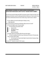
CLEANING THE MACHINE
The 420 should be cleaned daily to remove any dirt or dust
which may interfere with the operation of the machine. Paper
dust collected in motion areas could impede and/or damage
integral parts of the folder. Paper dust can also impede read
quality if it accumulates on the read heads and paper sensors.
Excess dirt or toner build-up (from laser printing) on the feed
belts could result in damage to the material and/or premature
wear of the feed belts. Therefore, it is important to perform the
following daily cleaning instructions:
1. Clean ALL Feed Belts.
2. Remove ALL Paper Dust.
3. Clean the Fold Rollers
4. Clean the Machine Cabinets and Covers.
GENERAL PROCEDURES
WARNING!
B.2a1 Cleaning the Fold Rollers
DO NOT ATTEMPT TO CLEAN THE SMART FEEDER WHEN
THE MACHINE IS RUNNING. ATTEMPTING TO DO SO
COULD RESULT IN INJURY. BE SURE THAT MACHINE
POWER IS OFF AT ALL TIMES WHEN CLEANING.
SMART FEEDER SERVICE MANUAL
All accumulated paper dust should either be brushed or
vacuumed from the 420. Clean all accumulated paper dust from
the electronic paper sensors.
B.2a2 Cleaning the Fold Rollers
DO NOT USE ANY LIQUID ON THE FOLD ROLLERS! The fold
plates must be removed in order to clean all fold rollers. For
ISSUE 09/00
PREVENTIVE MAINTENANCE
SECTION B – PAGE 1
SMART FEEDER SERVICE MANUAL
ISSUE 09/00
PREVENTIVE MAINTENANCE
SECTION B – PAGE 2
more information on cleaning the fold rollers, refer to your 420
Operator Manual.
that it is making sufficient contact to clean away all dirt and
debris from the contact portion of the singulator roller.
B.2a3 Machine Cabinets and Covers
B2.b
Clean the machine cabinets and covers using a soft damp cloth.
No lubrication is required on the 420.
B.2a4 Paper Hopper
NOTE: If a mechanical component is out of line or deformed, a
small amount of oil may be used as a short term fix (to eliminate
noise or binding) until the component can be replaced.
The feed belt should be cleaned with a substance such as
isopropyl alcohol that does not leave a film. Apply some alcohol
to a rag then lightly rub all dirt and film off of the belts.
B.2a5 Singulator
The Singulator must be as clean as possible at all times to
insure the proper feeding and singulation of paper by the feed
belt. This may be done first making sure that the singulator is
not worn. If so, loosen the small set screw on the operator side
and rotate the roller to a point where a rounded spot on the
roller will contact the paper.
NOTE: If there is no rounded spot available, the singulator
needs to be replaced immediately.
Once this is accomplished, raise the singulator roller approximately 3/4" from present setting. Pass an alcohol
dampened rag under the bottom of the singulator roller. Be sure
LUBRICATION
SECTION C - PROBLEM ANALYSIS
C.1
Machine Diagnostics ............................................................................... 2
C.2
Screen Operation..................................................................................... 2
C.2a
"INPUT" TEST MENU....................................................................3
C.2b
"OUTPUT" TEST MENU................................................................5
C.2c
"SPEED" TEST MENU ...................................................................6
C.2d
"SETUP" TEST MENU ...................................................................6
C.2e
CYCLE TEST MENU....................................................................11
C.2f
INSERTER TEST MENU ..................................................................11
C.2g
POSTAL METERING SETUP PRESETS.....................................14
C.3
Software Error Codes........................................................................... 18
C.3a
General Solutions to Errors ............................................................18
C.3b
Solutions to Less Common Errors ..................................................19
C.3c
Specific Errors, Causes and Solutions ............................................19
C.4p
C.4q
C.4r
C.4s
C.4t
C.4u
C.4v
C.4w
C.4x
C.4y
C.4z
C.4aa
SYMPTOM: Error in read - “page out of range” .............................46
SYMPTOM: Error in read - “presets corrupt” .................................46
SYMPTOM: Error in read - “yes no eog are same”..............................48
SYMPTOM: Error in accumulator - “jam/stall to ramps”................48
SYMPTOM: Error in accumulator - “Stall on ramp” ...........................48
SYMPTOM: Error in accumulator - “package did not dump”.........49
SYMPTOM: Error in accumulator - “package not removed” ..........49
SYMPTOM: Error in accumulator - “dump brake fail” ...................49
SYMPTOM: Error in accumulator - “in vs out speed” ....................49
SYMPTOM: Error in folder - “Doc jammed inside” ......................50
SYMPTOM: Error in folder - “Speed is too low”............................50
SYMPTOM: Error in folder - “folder too fast”................................50
C.4
Troubleshooting .................................................................................... 42
C.4a
SYMPTOM: Error in feeder - “no sheet was fed”.........................42
C.4b
SYMPTOM: Error in feeder - “short sheet” ..................................42
C.4c
SYMPTOM: Error in feeder - “long sheet”...................................42
C.4d
SYMPTOM: Error in feeder - “two sheets” ..................................43
Read errors .......................................................................................................... 43
C.4e
SYMPTOM: Error in read - “no response timeout” ......................43
C.4f
SYMPTOM: Error in read - “code misread”.......................................43
C.4g
SYMPTOM: Error in read - “group out of seq” .............................44
C.4h
SYMPTOM: Error in read - “expected end of group”....................44
C.4i
SYMPTOM: Error in read - “blank page”...........................................44
C.4j
SYMPTOM: Error in read - “short group”..........................................45
C.4k
SYMPTOM: Error in read - “duplicate page” ................................45
C.4l
SYMPTOM: Error in read - “page out of seq”....................................45
C.4m
SYMPTOM: Error in read - “invalid group”..................................46
C.4n
SYMPTOM: Error in read - “expected page one”..........................46
C.4o
SYMPTOM: Error in read - “group out of range”..........................46
SMART FEEDER SERVICE MANUAL
ISSUE 09/00
PROBLEM ANALYSIS
SECTION C – PAGE 1
SMART FEEDER SERVICE MANUAL
C.1
ISSUE 09/00
MACHINE DIAGNOSTICS
Diagnostics on the SMART FEEDER is performed through the
display panel and related software. Refer to section C2.
C.2
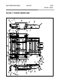
SCREEN OPERATION
There are several screens available through the display. These
screens provide set up, monitoring, and alteration capabilities
for the SMART FEEDER. They are illustrated in the charts
which follow.
READ - Refer to Section D for screen directions.
ON-OFF
SETUP
READ-TYPE
TEST
TEST - INPUT OUTPUT SPEED SETUP CYCLE INSERTER*
JOB - GET JOB SAVE JOB
SHEET LENGTH - 5.5 in 7 in 8.5 in 11 in 14 in A4 A5 A6
SIZE PACKAGE - 1 2 3 4 5 6 7 VARIABLE
INSERT 0:OFF
9:ON
INSERT TO PULL
STATION 8=0 7=0 6=6 5=5 4=4
3=3
PROBLEM ANALYSIS
SECTION C – PAGE 2
there is a line in the line code for that station if the lower line is
set to =9.
DIVERT BATCH SHEET - SHEET BATCH COUNT: < > UNDO/ ENTER
BATCH PKG - PACK BATCH COUNT: < > .. UNDO/ ENTER
*(if installed)
To access particular options, scroll through menu choices
using the < > keys on the key pad. When the desired option is
flashing, press the Enter key to select that choice.
Diagnosis of the system begins with these tests. If it is found
that the displayed information indicates a problem, refer to the
schematics in section D or section F.
#:SELECT
2=2 1=1
The # SELECT settings on the lower line determine which
inserts will be pulled when there is a line present in the line
code for that position. For instance, when using GBR Line
Code if there is a line present in the line code for the #4 station
and this screen has been set for 4=4, an insert will be pulled
from station #4. If the screen had been set to 3=4, an insert
would be pulled from station #3. On the upper line 0:OFF
indicates no inserts will be pulled if the lower line is set to zero
even if there is a line in the code for that station. 9:ON
indicates an insert will be pulled from a station whether or not
SMART FEEDER DISPLAY - FIGURE C-1
C.2a
"INPUT" TEST MENU
After pressing the TEST key, this message appears, asking
which test to perform.
SELECT TEST < > ENTER (ver. 07625.xxx)
INPUT OUTPUT SPEED SETUP CYCLE INSERTER (if installed)
Press the < or > key to scroll through the available choices
until INPUT is highlighted.
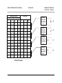
SELECT INPUT: < > .. + (MORE)
Rack:Opto
1
2
3
4
5
6
7
8
9
10
11
12
13
14
15
16
17
18
19
20
21
22
23
24
Feed Sensor
2 sheet Sensor
Feeder Speed Encoder
Acc Sensor
Stack Sensor
Folder Speed Encoder
Transfer Conv IN SNS
Transf. Conv. OUT SNS
Ins. Run Lamp
Inserter Deg. Encoder
Inserter Home Encoder
Key Power
Key Cycle
Key Dump
Paper Demand Wand
Demand Switch
Interlock
Conv Option Line 0
Conv Option Line 1
Conv Option Line 2
Inserter Sta. 1 Sns
Cutter Busy Signal
Cutter Jam Sensor
Ins Ink Mark Pres
SMART FEEDER SERVICE MANUAL
Press ENTER to select.
0:0
0:16
0:2
0:18
0:1
0:3
0:12
0:13
1:21
0:5
0:14
0:8
0:9
0:10
1:20
0:4
0:11
0:6
0:7
0:15
1:23
0:19
1:22
1:16
The display will then indicate the status of the input.
00/00:OFF:NAME
OFF, ON, or UNAVAILABLE
Physically change the input (for instance, cover a sensor) to
diagnose that the input is operating. Its state should change
as indicated on the display. Also, the LED on the associated
optical relay will be OFF or ON, depending on the state of the
input. Rack:Opto indicates the location of the associated
optical relay.
Press + to see information for each input as described below:
Located on:
Used for:
Part No.
Style:
Type:
Opto Rack:
ISSUE 09/00
PROBLEM ANALYSIS
SECTION C – PAGE 3
SMART FEEDER SERVICE MANUAL
ISSUE 09/00
OPTO RACKS - FIGURE C-2
PROBLEM ANALYSIS
SECTION C – PAGE 4
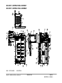
C.2b
"OUTPUT" TEST MENU
SELECT TEST < > ENTER (ver. 07625.xxx)
INPUT OUTPUT SPEED SETUP CYCLE INSERTER
SELECT OUTPUT: < > .. START + (MORE)
After pressing the TEST key, the SELECT TEST message
appears, asking which test to perform.
Press the < or > key to scroll through the available choices
until OUTPUT is highlighted.
Press ENTER to select.
The display will then indicate the status of the output.
00/00:OFF:NAME
OFF, ON, or UNAVAILABLE
Cycle the machine to change the output: note that the output
is operating. Its state should change as indicated on the
display. Also, the LED on the associated optical relay will be
OFF or ON, depending on the state of the input. Rack:Opto
indicates the location of the associated optical relay.
Press + to see information for each input as described below:
Located on:
Used for:
Part No.
Style:
Type:
Opto Rack:
SMART FEEDER SERVICE MANUAL
ISSUE 09/00
1
2
3
4
5
6
7
8
9
10
11
12
13
14
15
16
17
18
19
20
21
22
23
24
25
26
Feed Clutch
Feed Motor
Acc Dump Clutch
Acc Dump Brake
Folder Motor
Master Relay
Transfer Conv. Clutch
Transfer Conv. Brake
Separation Sol 1
Separation Sol 2
Separation Sol 3
Separation Sol 4
Separation Sol 5
Separation Sol 6
Separation Sol 7
Separation Sol 8
Separation Sol Encoder
Ink Marker Solenoid
Env Flap Sns Dis
Emr Stop
Ins Station 1 Error
Postal Meter divert
Paper Hopper Request
First Hold Clutch
First Hold Brake
Feeder Brake
(inserter signal)
(inserter signal)
(inserter signal)
(inserter signal)
(inserter signal)
(inserter signal)
(inserter signal)
(inserter signal)
(inserter signal)
(inserter signal)
(inserter signal)
(inserter signal)
(inserter signal)
(inserter signal)
Rack/Opto
1:0
1:2
0:20
0:23
1:1
1:3
0:21
0:22
1:5
1:8
1:9
1:10
1:11
1:12
1:4
1:16
1:13
1;14
1:15
1:16
1:17
1:19
1;18
2:15
2:14
2:13
PROBLEM ANALYSIS
SECTION C – PAGE 5
SMART FEEDER SERVICE MANUAL
C.2c
ISSUE 09/00
"SPEED" TEST MENU
SELECT TEST < > ENTER (ver. 07628.xxx)
INPUT OUTPUT SPEED SETUP CYCLE INSERTER
ALL SPEEDS IN IPS : EXIT TO LEAVE OR…
FEED: 165 FOLD: 115 DEMAND: OFF READ 150:
Note: IPS (inches per second).
The speeds indicated are approximate.
Press the ENTER key to start motors. Press the EXIT/UNDO
key to stop motors.
NOTE: The FEED and READ speeds must be within 5% of
each other to ensure normal operational condition.
C.2d
"SETUP" TEST MENU
SELECT TEST < > ENTER (ver. 07625.xxx)
INPUT OUTPUT SPEED SETUP CYCLE INSERTER
SELECT SETUP: < > .. UNDO EXIT
After pressing the TEST key, the SELECT TEST message
appears, asking which test to perform.
Press the < or > key to scroll through the available choices
until SETUP is highlighted.
Press ENTER to select.
PROBLEM ANALYSIS
SECTION C – PAGE 6
1
2
3
4
5
6
7
8
9
10
TWO SHEET DETECT DISABLE
TWO SHEET CHECK: < > .. UNDO/EXIT
ON OFF
EXIT CONTROL
SELECT: 0
CHOOSE TYPE LOWER LEFT DISPLAY
1/5 Total Sheets
2/5 Total Packages
3/5 Page in Package
4/5 OMR
5/5 No Display
CHOOSE TYPE LOWER RIGHT DISPLAY
1/6 Batch Sheet
2/6 Batch Package
3/6 Inserter Rate/Hour
4/6 Ave. Wait for Demand
5/6 OMR
6/6 No Display
CHOOSE NO USE SHUTDOWN TIME LENGTH
1 - 5 - 10 - 15 - OFF
PULSE FEEDING ENABLE
PULSE FEEDING ENABLE: < > .. UNDO/ EXIT
ON OFF
CHOOSE TYPE TRANSFER CONVEYOR
TYPE TRANSFER CONV.: < > .. UNDO/ EXIT
GRIPPER ARM HOPPER FILL OPEN FEED
DISPLAY BELL DISABLE
DISPLAY BELL: < > .. UNDO/ EXIT
ON OFF
CHOOSE TYPE PRE-FEEDER CONVEYOR
TYPE PRE-FEED CONV.: < > .. UNDO/ EXIT
SMART FEEDER SERVICE MANUAL
11
12
13
14
15
16
17
18
ISSUE 09/00
CREEPER ONLY 470 BULK CUTTER CONT.
HIGH COUNT STOP
1-10: < > …UNDO/EXIT
PERFORMANCE: < >…UNDO/EXIT
OFF ON
INSERTER: ONLINE/OFFLINE
< >…Enter
FIRST PAGE HOLD DELAY
FIRST PAGE HOLD DELAY: 05
CONFIG. ID (NOTE: Cycle machine power to set change)
XFER CONVEYOR (W/INSERTER)
STRAIGHT CONVEYOR
XFER CONVEYOR (STAND ALONE)
XFER CONVEYOR (W-INSERTER - P)
DUMP TO FEED DELAY TIMER SETUP
DUMP TO FEED :10 DUMP BRAKE: 05
DUMP DELAY TIMER SETUP
DUMP DELAY TIMER VALUE: 25
SERIAL COMMUNICATION PROTOCOL
SERIAL COMM PROTOCOL NUMBER: 0-5
FEED BRAKE ENABLE/DISABLE
FEED BRAKE: DISABLE ENABLE
PROBLEM ANALYSIS
SECTION C – PAGE 7
SMART FEEDER SERVICE MANUAL
ISSUE 09/00
1/18 Two Sheet Detect Disable is normally set to "ON" but
can be turned off if varying thickness stock is being run or if
printing on the stock is affecting the double detect sensor.
2/18 EXIT CONTROL is normally set to”0”.
0 Standard Inserter Control
1 12 Bit Control (preliminary)
2 8 Bit Collector Control (preliminary)
3/18 Lower Left Display can be customized to the operator's
preference.
4/18 Lower Right Display can be customized to the
operator's preference.
5/18 No Use Shutdown Time Length sets the time the Smart
Feeder will run without being used before it cycles down.
6/18 Pulse Feeding Enable is normally turned "OFF". When
turned "ON" the feeder will place a larger gap between the
sheets being fed.
7/18 Choose Type Transfer Conveyor is normally set to
"GRIPPER ARM" when the inserter will be taking the folded
document from the Smart Feeder. Select "HOPPER FILL"
when the inserter will be taking the folded documents from a
hopper. Select "OPEN FEED" when the Smart Feeder will be
placing the folded documents directly on the inserter track.
8/18 Display Bell Disable is normally set to "ON". Turning
this "OFF" will turn the bell on the Smart Feeder display off.
PROBLEM ANALYSIS
SECTION C – PAGE 8
9/18 Choose Type Pre-Feeder Conveyor is normally set to
"CREEPER ONLY".
10/18 High Count is normally set at “7”. High Count allows
the operator to define the number of documents in a group
which will trigger a required stop. Operator can then process
the group manually. This might be used to accommodate odd
groups in metered mail applications.
1.
2.
3.
4.
5.
Press the TEST button.
Scroll to SETUP.
Press ENTER button.
Scroll to feature 10 of 10: HIGH COUNT STOP.
Press ENTER button. Menu will display, “HIGH COUNT
STOP.” This parameter should be set to “7” (from the
factory) but can range from 1 to 10. Use settings greater
than "7" only when processing "V-folds".
6. Enter the number of documents representing the highest
total documents in a group.
7. Press ENTER.
When the SmartFeeder accumulates the set number of
documents and recognizes that it is not the end of a group,
the machine will stop and an error message will be displayed:
MAX PAGES IN ACCUM. (single cycle)
MAX SHEETS IN ACCUM. (auto cycle)
Remove the document packet and reset the machine to
resume operation.
Process the removed packet manually.
If the error occurs but the document packet is correct, make
sure the High Count Stop is set to the proper value (see
above).
11/18 Performance OFF is the normal setting, however if
increased throughput of the Smart Feeder is needed to
maintain the speed of the interfaced unit then Performance
ON should be selected. If this mode is set to "ON" Setup 15
(DUMP TO FEED DELAY) should be set to 05 and Setup 16
(DUMP DELAY TIMER SETUP) should be set to 40. These
settings may need to be adjusted if other than 11" documents
are being fed.
12/18 Inserter ONLINE allows the Smart Feeder to control
the operation of the inserter. OFFLINE returns control to the
inserter, allowing the operator to run the inserter as a
standalone unit.
This feature only works if the optional AC/DC opto logic kit
is installed
This feature replaces the “Dummy Plug” that needed to be
installed for inserter “off-line” operation.
13/18 First Page Hold Delay is normally set at 05. If the
First Page Hold Option is installed on the Smart Feeder this
time can be adjusted to leave a document on the accumulator
ramps for a longer period of time if necessary.
15/18 Dump to Feed Delay Timer Setup is normally set to
"10" ("30" if First Page Hold is being used). A "DUMP TO
FEED DELAY" of less than 10 may cause the first page of the
set to be passed to the accumulator while the dump clutch is
still engaged causing a "DUMP BRAKE FAILURE" error.
The amount of time allotted to the reader is dictated by the
value of the single digit place, 0 being the shortest time and 9
the longest time allotted for a reading. This should be set as
low as possible without causing a "Blank Page' error. The
tens digit place is only used in setting the amount of time from
an accumulator dump to when the next sheet is fed. It does
not affect the time allotted for a reading. The single digit place
however, does affect the feed delay time.
“DUMP BRAKE” is normally set to “5”ms. This time period is a
delay in energizing the Dump Brake after a package has left
the accumulator section and into the folder section. This delay
allows the package to clear the dump rollers before the Dump
Brake is energized. Should the trailing edge of the package
get stopped in the dump rollers, increase this time until the
package clears the rollers. The range of this variable is 0 to
99ms, but should be kept as short as possible to not effect
performance.
16/18 Dump Delay Timer Setup is set to 25 for normal run
and 40 when First Page Hold is being used.
14/18 Config. ID is normally set to XFER CONVEYOR
(W/INSERTER). XFER CONVEYOR (W-INSERTER - P) is selected
when an insert from the Smart Feeder may not be desired and
always selected when feeding a Pinnacle inserter. Refer to
Section for more information on
SMART FEEDER SERVICE MANUAL
ISSUE 09/00
PROBLEM ANALYSIS
SECTION C – PAGE 9
SMART FEEDER SERVICE MANUAL
ISSUE 09/00
17/18 Serial Communication Protocol - If RS232
communications to an external device will be used, the correct
external device protocol must be selected:
0 No external device
1 RR Donnelly Short message output.
2 RR Donnelly Long message output.
3 Pinnacle old message output.
4 Pinnacle new, EDA-5109, message output.
5 General Message output.
Pinnacle new plus
Group number on end.
18/18
FEED BRAKE ENABLE / DISABLE
“FEED BRAKE:” is normally set to DISABLE. This setup
option allows ENABLING or DISABLING the energizing of a
feeder brake when the Feed Clutch is de-energized. Should
the paper in the feeder section begin to prematurely exit under
the pinch roller (due to higher operation speeds) and block the
feed sensor, then the FEED BRAKE can be enabled to retard
the paper feed. This feed brake is only available on the Model
438 and the enable or disable will not affect earlier production
machines.
PROBLEM ANALYSIS
SECTION C – PAGE 10
C.2e
CYCLE TEST MENU
C.2f
INSERTER TEST MENU
SELECT TEST < > ENTER (ver. 07625.024)
INPUT OUTPUT SPEED SETUP CYCLE INSERTER
This is only available if the CONFIG ID SETUP (Section C2.d)
is set to XFER CONVEYOR (W/INSERTER).
SELECT CYCLE TEST: < > .. UNDO/ EXIT
SELECT TEST < > ENTER (ver. 07625.024)
INPUT OUTPUT SPEED SETUP CYCLE INSERTER
After pressing the TEST key, the SELECT TEST message
appears, asking which test to perform.
Press the < or > key to scroll through the available choices
until CYCLE is highlighted.
INSERTER SETUP: < > .. UNDO/ EXIT
ENCODER TEST/TIMING
INSERTER ENCODER POSITION .. UNDO
DEGREES:000
HOME:0
Press ENTER to select.
1
2
3
4
CYCLE ACCUMULATOR CLUTCH/ BRAKE
CYCLING ACCUMULATOR .. UNDO/ EXIT
SIMULATING 10,000 PACKAGES PER HOUR
CYCLE FEEDER CLUTCH
CYCLING FEEDER .. UNDO/ EXIT
SIMULATING 10,000 PACKAGES PER HOUR
CYCLE ENTIRE SYSTEM
CYCLING SYSTEM .. UNDO/ EXIT
SIMULATING 10,000 PACKAGES PER HOUR
CYCLE TRANSFER CLUTCH/ BRAKE
CYCLE TRANSFER CONVEYOR .. UNDO/ EXIT
SIMULATING 10,000 PACKAGES PER HOUR
Scroll through the choices within the option and press ENTER
to accept.
SMART FEEDER SERVICE MANUAL
ISSUE 09/00
PROBLEM ANALYSIS
SECTION C – PAGE 11
SMART FEEDER SERVICE MANUAL
ISSUE 09/00
TIMING
SELECT TIMING TO SET: < > .. ENTER
1
INSERT VACUUM
INSERT VACUUM
+- UNDO/ EXIT
ENABLE AT: 100
2
ENVELOPE HOPPER VACUUM
ENVELOPE HOPPER VACUUM +- UNDO/ EXIT
ON AT: 230 Insert Sta -:2
3
ENVELOPE FLAP DETECT
ENVELOPE FLAP DETECT +- UNDO/ EXIT
ON AT: 010 OFF AT: 350 Insert Sta -:1
4
INK MARKING
INK MARK +- UNDO/ EXIT
ON AT: 010 OFF AT: 180 STA. AT: 00
5
POSTAL METER DIVERT 1
ON at: 200 OFF at: 010 STA: 07 PT: 09
6
LOGICAL SHIFT
LOGICAL SHIFT +- UNDO/ EXIT
ENABLE AT: 090
7
BAD PACKAGE STOP
BAD PACKAGE STOP +- UNDO/ EXIT
ENABLE AT: 080
8
NUMBER OF INSERT STATIONS
GRIPPER LAYOUT: < > .. UNDO/ EXIT
4 6 4+4 6+4 4+6 654321
9
NUMBER OF EMPTY STATIONS (MUST BE ENTERED)
NUMBER OF EMPTY STA. +- UNDO/ EXIT
STATIONS: 02
10
ENCODER TYPE
PROBLEM ANALYSIS
SECTION C – PAGE 12
11
12
13
14
15
16
17
18
SELECT ENCODER TYPE: < > .. UNDO/ EXIT
B&H ROTATIONAL POSITION BOX 36 TICK/ REV.
GBR 100 TICK ENCODER
OPTO LOGIC TYPE
SELECT OPTO TYPE: < > .. UNDO/ EXIT
AC/DC DUMB INSERTER
LEFT HAND CONTROL CARD (775)
POSTAL METER 2
ON at: 240 OFF at: 010 STA: 07 PT: 01
(NOT USED)
POSTAL METER 3
ON at: 280 OFF at: 010 STA: 07 PT: 02
POSTAL METER WEIGHTS
METER 1 to 2: 00000 METER 2 to 3: 00000
WEIGHT PAGE AND ENVELOPE
PAGE: 00000 ENVELOPE: 00000
WEIGHT INSERTS 1234
>: 00000 >: 00000 >: 00000 >: 00000
WEIGHT INSERTS 5678
>: 00000 >: 00000 >: 00000 >: 00000
Note: Insert Station positions are referenced from the station
at which the documents are inserted into the envelope ("Insert
Sta: 0"). Insert Station 1 would be the station downstream
from Insert Station 0. Insert Station -1 is the Insert Station
upstream from Insert Sta 0.
1 Insert Vacuum is normally enabled at "100". This is the
position of the encoder (in degrees) at which vacuum is
applied to the insert station.
2 Envelope Hopper Vacuum is normally enabled at "230".
This is the position of the encoder (in degrees) at which
vacuum is applied to the envelope hopper. Insert Sta -: is
normally set at -2.
3 Envelope Flap Detect is normally set On at: 010, Off at:
350, and Insert Sta -:1(this is the location of the flap
detect).
4 Ink Marking is an optional device that places an ink mark
in varying locations to sort zip codes visually. "OFF" is the
number of chain movements AFTER envelope insertion.
NOTE ON POSTAL METER WEIGHING: The 420 can
accommodate up to three postal meters. Based on the values
entered in "Postal Meter Weights", "Weight Page and
Envelope", "Weight Inserts 1234", and "Weight Inserts 5678"
the document will be stamped by the appropriate postal meter.
The dollar value must be manually entered in the postal
meter.
1 Enter the weight of the individual document in the PF300 in
16 "Weight Page and Envelope".
SMART FEEDER SERVICE MANUAL
ISSUE 09/00
2 Enter the weight of an individual envelope in 16 "Weight
Page and Envelope".
3 Enter the weight of each insert in stations 1-4 (17 "Weight
Inserts 1234") and stations 5-8 (18 "Weight Inserts
5678").
4 Enter the upper weight limit of the entire envelope package
for postage meter 1 and 2 in 15 "Postage Meter Weights".
5 Enter "ON at:xx" value for 5- "Postal Meter 1", 12- "Postal
Meter 2", and 14- "Postal Meter 3". Normally these value
are 200,240,and 280 respectively. If one of these values
must be changed the others should also be changed to
remain 40 apart from each other.
6 Enter "OFF at: 010" for Postal Meter 1, 2, and 3.
7 Enter the Postal Meter Station "STA: 00" (see Postal Meter
1, 2, and 3).
8 Enter the postal meter output point to the 420 (see Postal
Meter 1, 2, and 3).
The 420 will total the weights of all documents, inserts, and
the envelope and then send it to the correct postal meter.
5 Postal Meter 1 is normally set to "ON at: 200". This will
enable the postal meter at the correct time. This value may
need to be adjusted if the postal meter doesn't place the
postage in the correct place. Postal Meter 2 should then
be set to 40 higher than the new meter 1 value and postal
meter 3 should be 40 higher than 2. "OFF at: xx" should
be set to "010". "STA:00" is set to the value of the last
chain section of the inserter after the envelope stuffer and
the turnover (04, 05, 06, 07, etc.), this is normally set to
PROBLEM ANALYSIS
SECTION C – PAGE 13
SMART FEEDER SERVICE MANUAL
ISSUE 09/00
"07" on a six station inserter. "PT:xx" selects the postal
meter output line to the 420, this is normally set to "9".
6 Logical Shift is normally set to "ENABLE at:090". This is
used to carry the data with the physical document.
7 Bad Package Stop is normally set to "ENABLE at:080".
8 Number of Insert Stations should be selected to match
your inserter configuration.
IMPORTANT: Number of Empty Stations must be set
correctly for Postal Meter Weighing to work correctly.
9 Number of Empty Stations are the number of stations
that do not have inserters. This would be the space taken
by the 420, usually 02.
10 Encoder Type (select your encoder type).
11 Opto Logic Type (select your type).
12 Postal Meter 2 (see Postal Meter 1), PT:xx is usually set
to "01".
13 (Not Used)
14 Postal Meter 3 (see Postal Meter 1), PT:xx is usually set
to "02".
15 Postal Meter Weights should be set to the upper weight
limit of Postal Meter 1 for "METER 1 to 2:00000 and the
upper weight limit of Postal Meter 2 for "METER 2 to
3:00000.
16 Weight Page and Envelope should be set to the weight of
a single sheet from the 420 for "PAGE: 00000" and the
weight of an envelope for "ENVELOPE: 00000".
PROBLEM ANALYSIS
SECTION C – PAGE 14
17 Weight Inserts 1234 should be set to the weight of an
insert for each insert station (1-4).
18 Weight Inserts 5678 should be set to the weight of an
insert for each insert station (5-8).
C.2g POSTAL METERING SETUP PRESETS
The following are ‘Typical Presets’ for the Smart Feeder
configured for 6-Station AC/DC Open Feed Inserter Control
with two postal meters, Meter 2 and Meter 3, Meter 1 and
Meter 2. This may vary from your actual application.
Test - "Setup"
Double Detect
Presets Reset
Lower Left Display
Lower Right Display
No Use Timeout
Pulse Feed
Type of Transfer
Beep/Bell
Input Conveyor
High Count Stop
Performance
Inserter Online/Offline
First Page Hold delay
Config ID
Dump to Feed Delay Setup
Dump Delay Timer Setup
ON
NA
OMR
OMR
OFF
ON
OPEN FEED
ON
2000 Sheet Conveyor
07
Off
Online
30
Xfer Conveyor(W/Inserter)
05
25
Test - "Inserter"
Insert Vacuum Enable
Envelope Hopper Vacuum
On at:100
On at:230
Insert Sta.-:2
Envelope Flap Detect
On at:010
Off at:350
Insert Sta.-:1
Ink Marking
On at:010
Off at:010
Insert Sta.:00
Postal Meter Divert
On at:200 (First Meter inline
when Meters 1 and 2 tested)
Off at:010
Insert Sta.:07
Logical Shift
Enable at:090
Bad Package Stop
Enable at:080
Number of Insert Stations
6
Number of Empty Stations
2
Encoder Type
GBR 100 Tick Encoder
Opto Logic Type
AC/DC Dumb Inserter
Postal Meter 2
On at:200(for first Meter
inline, 240 if second meter inline)
Off at:010
Insert Sta.:07
Pt:1
Postal Meter 3
On at:200(for first Meter
inline, 240 if second meter inline)
Off at:010
Insert Sta.:07
Pt:2
Postal Meter Weights
Meter 1 to 2: 00004 Meter 2 to 3:
00005
SMART FEEDER SERVICE MANUAL
ISSUE 09/00
Weight Page and Envelope Page: 00001 Envelope: 00001
>: 00001 >: 00001 >: 00001
Weight Inserts 1 2 3 4 >: 00001 >: 00001 >: 00001 >: 00001
Weight Inserts 5 6 7 8 >: 00001 >: 00001 >: 00001 >: 00001
PROBLEM ANALYSIS
SECTION C – PAGE 15
SMART FEEDER SERVICE MANUAL
Read - "T.J. Line"
Demand Feed
Page sequence
Group Sequence
Ink Mark
Postal Meter Divert
Parity
End of Subset
Random Check Mark
Blank Page Error Stop
Number of Windows
Window Setup
Lines Per Inch
Probe A or B
Bit Weight
Calibration
Tolerance
Code Field Format
EOG
Page
Group
Inserts
Postal Meter Divert
Subset
Parity
Random Check Mark
Read - "Bar"
Job Setup
Stop for Read Errors
ISSUE 09/00
PROBLEM ANALYSIS
SECTION C – PAGE 16
‘READ(LINEREAD)’ to ‘SETUP’ Menu:
Normal
Item Count
Off
Off
Off(Off = NO divert by mark and
YES Meter 1 Weight)
None
Off
Off
On
1
1: Begin:07 Length:16
6
A
LSB First
Off
Low
EOG:00 NOT EOG:00
Begin:5 Length:3 Min:1 Max:7
Begin:2 Length:3 Min:1 Max:4
Begin:10 Length:6 Max:6
At Line:0
At Line:0 By Count Size:0
At Line:0
At Line:0 Repeat Every:0
Job 41
Yes
Postal Meter Divert Enable(Postal Meter 1).
(May operate from a read mark as before. Consult the
420 Operating Manual)
Select Postal Meter Divert Enable “ON”, to operate from
a Lineread mark.
Select Postal Meter Divert Enable “OFF”, to operate from
Weights.
‘TEST’ to ‘INSERTER’ to ‘TIMING’ Menu:
Postal Meter Divert(Postal Meter 1)
Enter Meter “ON AT:’ in degrees, 0 to 350.
Enter Meter “OFF AT:’ in degrees, 0 to 350.
Enter Meter Position ‘STA:’ (1 to 12 after envelope insert
station)
Postal Meter 2
Enter Meter “ON AT:’ in degrees, 0 to 350.
Enter Meter “OFF AT:’ in degrees, 0 to 350. Not Used
Enter Meter Position ‘STA:’ (1 to 12 after envelope insert
station)
Enter Meter Output Point Option ‘PT:’
1 = Station 7 Select - Default
2 = Station 8 Select
3 = Inserter E-Stop
4 = Station 1 Error
5 = Station 7 Select - Inverted Signal
6 = Station 8 Select - Inverted Signal
7 = Inserter E-Stop - Inverted Signal
8 = Station 1 Error - Inverted Signal
Postal Meter 3
Enter Meter “ON AT:’ in degrees, 0 to 350.
Enter Meter “OFF AT:’ in degrees, 0 to 350. Not Used
Enter Meter Position ‘STA:’ (1 to 12 after envelope insert
station)
Enter Meter Output Point Option ‘PT:’
1 = Station 7 Select
2 = Station 8 Select - Default
3 = Inserter E-Stop
4 = Station 1 Error
5 = Station 7 Select - Inverted Signal
6 = Station 8 Select - Inverted Signal
7 = Inserter E-Stop - Inverted Signal
8 = Station 1 Error - Inverted Signal
Enter Insert >6 Weight Value(00000 to 60000)
Enter Insert >7 Weight Value(00000 to 60000)
Enter Insert >8 Weight Value(00000 to 60000)
Operation
Package Weight less or equal(<=) to Meter 1 to 2 Weight
Value
Meter 1 operates.
Package Weight greater than Meter 1 to 2 Weight Value
and less or equal(<=) to Meter 2 to 3 Weight Value
Meter 2 operates.
Package Weight greater than Meter 2 to 3 Weight Value
Meter 3 operates.
Postal Meter Weights
Meter 1 to 2 Weight Value(00000 to 60000)
Meter 2 to 3 Weight Value(00000 to 60000)
Weight Page and Envelope
Enter Page Weight Value(00000 to 60000)
Enter Envelope Weight Value(00000 to 60000)
Weight Inserts 1 2 3 4
Enter Insert >1 Weight Value(00000 to 60000)
Enter Insert >2 Weight Value(00000 to 60000)
Enter Insert >3 Weight Value(00000 to 60000)
Enter Insert >4 Weight Value(00000 to 60000)
Weight Inserts 5 6 7 8
Enter Insert >5 Weight Value(00000 to 60000)
SMART FEEDER SERVICE MANUAL
ISSUE 09/00
PROBLEM ANALYSIS
SECTION C – PAGE 17
SMART FEEDER SERVICE MANUAL
C.3
SOFTWARE ERROR CODES
C.3a
General Solutions to Errors
ISSUE 09/00
Many error codes are the result of jammed paper (physical
errors), or paper expected at specific time and location (read
errors: sequence, blank page, misprinted code, etc.).
The sensors index the number of sheets as they pass,
incrementing a count on the CPU-186 . If a corresponding
decrement of count does not occur from the next sensor, a
read error is generated. If error persists, consider failure of
sensor or communication problem (poor connection, etc.).
For many read errors, check that setup parameters are correct
before pursuing functional troubleshooting.
Read errors require a determination of the integrity of the
pack. The operator must look at the readings on the display
and manually verify each sheet.
When read errors occur, it indicates that the integrity of the
package is in question. The SMART FEEDER was not able to
verify a page while stream feeding a package. When the
operator is satisfied that the package is complete, press the
DUMP key to release the package.
PROBLEM ANALYSIS
SECTION C – PAGE 18
Once a reading error (BLANK or MISREAD) is declared,
additional feeding via the CYCLE key will continue to display
BLANK or MISREAD errors, but will not stop the machine.
Before powering up the SMART FEEDER, the operator must
remove any packages in the accumulator to be sure there will
be no initial error conditions.
C.3b
Solutions to Less Common Errors
C.3c
A rare, but more difficult-to-find problem can occur with shorts
in the 24VDC circuit. Intermittent failure of sensors (5VDC
supply) can result from the 24VDC short. The short will only
occur when a 24V component activates, dropping the 5V
supply across the line. The 24V solenoid may be located
some distance from the sensor which is the apparent problem:
consider what is supposed to happen before or as the sensor
is supposed to read.
Specific Errors, Causes and Solutions
Refer to the tables on the following pages to identify likely
causes and the possible solutions to errors.
If either the Feeder speed or Folder speed are approximately
half of the other, an encoder channel is probably lost. (Check
speeds through Test menu on display.)
Any time a new CPU-186 board is installed, the presets must
be reset, or there will be an error displayed.
If PWB errors occur (errors with PWB as probable source),
pull the board and make sure that all board components are
properly seated. Re-install the board and make sure it is
properly seated.
If reader problems are recurring, re-calibrate with the
calibration sheet. Feed the sheet through several times to
ensure that the reader encoder is returning good data. If data
is inconsistent, replace the reader encoder.
An “invalid calibration” error indicates that the calibration
reading was more than 15% different from the expected
(stored) result. See above.
SMART FEEDER SERVICE MANUAL
ISSUE 09/00
PROBLEM ANALYSIS
SECTION C – PAGE 19
SMART FEEDER SERVICE MANUAL
ISSUE 09/00
PROBLEM ANALYSIS
SECTION C – PAGE 20
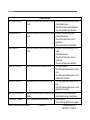
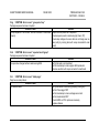
BAR CODE READER ERRORS
NO RESPONSE TIMEOUT
Answer not received, document in accumulator 1) Incorrect user input
2) Bad CPU-186 board
3) Blank CPU-186 board
4) Check, clean and adjust scanner
INVALID COMMAND
Unexpected signal
1) Incorrect user input
2) Bad CPU-186 board
BAD READ
Misread document
1) Blank or bad bar code
2) Check, clean and adjust scanner
PAGE OUT OF SEQUENCE
Page or roll sequence out of order in bar code 1) Incorrectly printed document
2) Documents out of order
3) Code not seen
4) Check, clean and adjust scanner
PRESETS CORRUPT
1) Battery jumper removed from CPU-186
2) Bad CPU-186 board
MAX NOT = NO. PAGES
Incorrect page count in accumulator
1) Page count setting incorrect
2) EOG mark not seen
3) Read error
INVALID CUST. ID.
1) Customer ID changed in the middle of a
package
GROUP SEQUENCE ERROR Group out of sequence
1) Incorrectly printed document
2) Documents out of order
3) Code not seen
4) Check, clean and adjust scanner
GROUP CHANGED IN SET
Group out of sequence
1)
2)
3)
4)
Incorrectly printed document
Documents out of order
Code not seen
Check, clean and adjust scanner
SMART FEEDER SERVICE MANUAL
ISSUE 09/00
PROBLEM ANALYSIS
SECTION C – PAGE 21
SMART FEEDER SERVICE MANUAL
ISSUE 09/00
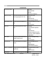
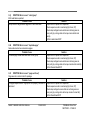
ROLL 7 OUT OF SEQ.
Roll sequence out of order
EXPECTED END OF GRP.
Page out of sequence
EXPECTED PAGE ONE
Page out of sequence
READER ERROR
Documents not processing
NO RESPONSE/BLANK PG
Scanner did not see bar code
JOB CHANGED IN RUN
Job number changed in the bar code
GROUP DID NOT CHANGE
Expected different group number
BAD CHECK DIGIT
Check digit in code is wrong
SHORT GROUP
EOG read before expected
PROBLEM ANALYSIS
SECTION C – PAGE 22
1)
2)
3)
4)
1)
2)
1)
2)
3)
4)
1)
2)
3)
1)
2)
3)
4)
1)
2)
3)
1)
2)
3)
4)
1)
2)
1)
2)
Incorrectly printed document
Documents out of order
Code not seen
Check, clean and adjust scanner
EOG mark not seen
Read error
Incorrectly printed document
Documents out of order
Code not seen
Check, clean and adjust scanner
Incorrectly printed document
Code not seen
Adjust feed sensor
Incorrectly printed document
Documents out of order
Code not seen
Check, clean and adjust scanner
Job setting incorrect
Reader error
Check, clean and adjust scanner
Incorrectly printed document
Documents out of order
Code not seen
Check, clean and adjust scanner
Code not seen
Check, clean and adjust scanner
Documents out of order
Code not seen
3) Check, clean and adjust scanner
SMART FEEDER SERVICE MANUAL
ISSUE 09/00
PROBLEM ANALYSIS
SECTION C – PAGE 23
SMART FEEDER SERVICE MANUAL
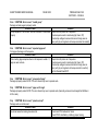
JAM/ STALL TO RAMPS
JAM/ STALL ON RAMPS
PACKAGE DID NOT DUMP
PACKAGE NOT REMOVED
DUMP BRAKE FAILED
IN Vs OUT SPEED
FAILED PRESENCE SNS
UNEXPECTED SHEET
STATE DIDN'T CHANGE
ISSUE 09/00
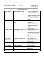
ACCUMULATOR ERRORS
A document stalled before the stack sensor.
1)
2)
A document stalled at the stack sensor.
1)
2)
The package did not leave the accumulator 1)
when the discharge clutch was activated.
2)
PROBLEM ANALYSIS
SECTION C – PAGE 24
Accumulator jam.
The stack sensor is out of adjustment
Accumulator jam.
The stack sensor is out of adjustment
The dump nip rollers are out of adjustment.
The accumulator presence sensor is out of
adjustment
3) The dump clutch has failed
4) Paper dust
A package is still in the accumulator after 1) The accumulator presence sensor is out of
POWER/ON reset
adjustment
2) The accumulator presence sensor has failed
The package left the accumulator when it was 1) The dump nip rollers are out of adjustment.
not intended to.
2) The accumulator presence sensor is out of
adjustment
3) The accumulator presence sensor is out of
adjustment
4) The dump brake has failed
Folder and feeder speed are out of adjustment 1) KBIC settings need adjustment
2) Belts slipping
3) Encoder or tachometer failure
Documents not seen in accumulator
1) Paper dust
2) The accumulator presence sensor is out of
adjustment
Document in accumulator was not expected by 1) Adjust feed stack sensors
the software
Software routines could not compete a task
1) Restart machine
2) Check 5VDC and 24VDC power supplies
SMART FEEDER SERVICE MANUAL
ISSUE 09/00
PROBLEM ANALYSIS
SECTION C – PAGE 25
SMART FEEDER SERVICE MANUAL
ISSUE 09/00
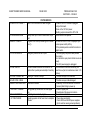
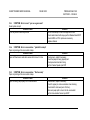
NO SHEET WAS FED
FEEDER ERRORS
Attempt to feed a document failed.
SHEET WAS TOO SHORT
A sheet was measured shorter than expected
SHEET WAS TOO LONG
A sheet was measured longer than expected
EXTRA SHEET WAS FED
Two sheets fed together more than one sheet's
thickness was detected at the feed sensor.
BLOCKED FEED SNS
Obstruction of feed sensor during power up
PROBLEM ANALYSIS
SECTION C – PAGE 26
1) The singulator/feeder belts are improperly
adjusted
2) The hopper is out of paper
3) The hopper is out of paper
1) A jam occurred at the feed sensor.
2) The user selectable length (preset by
MODE key is too long
3) The feed sensor and/or accumulator
presence sensor need adjustment
1) Two sheets were fed shingled (thus
increasing the apparent document length).
2) The user selectable length is too short
3) The feed sensor needs adjustment
4) The pullout rollers in front of the singulator
need adjustment
5) Paper of debris left on feed sensor upon
power up
1) Two or more sheets were fed.
2) The feed sensor needs adjustment (see
double detect sensor adjustment
procedure)
3) There is excessive printing in the extreme
left hand margin
4) Feed sensor is block by dust
1) The feed sensor needs adjustment
2) The pullout rollers in front of the singulator
need adjustment
CONVEYOR TOO SLOW
NV-RAM DATA CORRUPT
Data in the non-volatile ram was changed.
NOT ENOUGH NV-RAM
Battery back up on the non-volatile ram chip is
bad.
Program error internal processing error number
one (1).
PRESETS CORRUPT
FEEDER IS TOO FAST
STATE DIDN'T CHANGE
Feeder software routines could not finish a task
HOPPER EMPTY/JAM
An attempt to feed a document failed.
CUTTER JAM (BUSY)
Cutter is busy for more than 2 seconds
CUTTER JAM (READY)
Cutter did not respond with a busy signal
CUTTER JAM ( test )
Cutter is busy when starting a machine cycle
CUTTER JAM (SENSOR)
Cutter detects a jammed document
SMART FEEDER SERVICE MANUAL
ISSUE 09/00
3)
1)
2)
1)
Paper dust on sensor
Feed motor KBIC out of adjustment
Motor unplugged
Power to the CPU-186 was unplugged
directly at the board
2) Noise in the 120 VAC power
3) Battery jumper removed form CPU-186
1) Ram needs to be replaced.
1) Should not occur. If error is displayed cycle
the main power switch (off/on)
2) If the problem persists contact GBR field
service department
3) Bad CPU-186 board
1) Feed motor KBIC out of adjustment
1) State of feed sensor incorrect (ON should be
OFF, or vice versa)
1) The singulator/feeder belts are improperly
adjusted
2) The hopper is out of paper.
3) The feed sensor needs adjustment.
4) The feed sensor has failed.
1) Check cutter for jammed document
2) Check connections to cutter
1) Check cutter for jammed document
2) Check connections to cutter
1) Check cutter for jammed document
2) Check connections to cutter
1) Check cutter for jammed document
2) Check connections to cutter
PROBLEM ANALYSIS
SECTION C – PAGE 27
SMART FEEDER SERVICE MANUAL
PRESETS CORRUPT
ISSUE 09/00
Memory values out of range
PROBLEM ANALYSIS
SECTION C – PAGE 28
1) Battery jumper removed from CPU-186
2) Battery failed or battery jumper missing
3) Bad CPU-186 board
DOC JAMMED INSIDE
STALL/JAM EXITING
STALL/JAM INTO
SPEED IS TOO SLOW
FOLDER ERRORS
Folder jam a document has not exited the folder 1)
in time.
2)
3)
4)
Folder jam a document has not exited the folder 1)
in time.
2)
3)
4)
Folder jam a document has not exited the folder 1)
in time.
2)
3)
Folder speed is below 30 inches per second
4)
1)
2)
3)
FOLDER IS TOO FAST
Folder speed is above 150 inches per second.
1)
2)
UNEXPECTED PACKAGE
STATE DIDN'T CHANGE
Package in accumulator was not expected by the 1)
software
2)
Folder software routines could not finish a task 1)
2)
SMART FEEDER SERVICE MANUAL
ISSUE 09/00
A document has jammed inside the folder
A buckle plate is open
The out from folder is out of adjustment
The out from folder sensor has failed
A document has discharge sensor
A buckle plate is open
The out from folder sensor is out of
adjustment
The out from folder sensor has failed
A document has jammed going into the
folder
A buckle plate is open
The out from folder sensor is out of
adjustment
The out from folder sensor has failed
The folder is jammed
The folder speed potentiometer is set too
slow
The folder speed encoder sensor is out of
adjustment or has failed
The folder speed potentiometer is set too
high
The folder speed encoder sensor is out of
adjustment or has failed
Adjust accumulator presence sensor
Adjust transfer conveyor infeed sensor
Restart machine
Check 5VDC and 24VDC power supplies
PROBLEM ANALYSIS
SECTION C – PAGE 29
SMART FEEDER SERVICE MANUAL
ISSUE 09/00
PROBLEM ANALYSIS
SECTION C – PAGE 30
GBR READER ERRORS
INVALID GROUP
Group sequence has changed within a package, 1) Misread.
to group out of sequence.
2) Bar code misprinted.
EXPECTED PAGE ONE
First page of package is out of sequence.
1) Correct page sequence.
2) Check sequence count in read setup (Up,
Down, Off).
GROUP OUT OF RANGE
Bad Group the group ID number has changed 1) A page from another group is mixed in with
within the same package.
the same page number.
2) Misread.
PAGE OUT OF RANGE
The page numbers within the package are not in 1) The pages within this group are switched or
sequential order.
missing.
2) Misread.
NV-RAM DATA CORRUPT
Data in the non-volatile ram was changed.
1) Power to the CPU-186 was unplugged
directly at the board.
2) Noise in the 120 VAC power.
PRESETS CORRUPT
Program error internal processing error number 1) Should not occur. If error is displayed cycle
one (1).
the main power switch (off/on).
2) If the problem persists contact support
3) Misprint of bar code.
YES NO EOG ARE SAME
(European) Mismatched group marks cause stall 1) EOG and /EOG marks in same code
in accumulator
2) No EOG or /EOG mark in same code
3) Misprinted bar code.
INSERTER ERRORS
NV-RAM DATA CORRUPT
Data in the non-volatile ram was changed.
1) Power to the CPU-186 was unplugged
directly at the board
2) Noise in the 120 VAC power
3) CPU-186 battery jumper removed
NOT ENOUGH NV-RAM
Battery back up on the non-volatile ram chip is 1) Ram needs to be replaced.
bad.
PRESETS CORRUPT
Program error internal processing error number 1) Should not occur. If error is displayed cycle
SMART FEEDER SERVICE MANUAL
ISSUE 09/00
PROBLEM ANALYSIS
SECTION C – PAGE 31
SMART FEEDER SERVICE MANUAL
one (1).
ISSUE 09/00
PROBLEM ANALYSIS
SECTION C – PAGE 32
the main power switch (off/on)
2) If the problem persists escalate service
LINE READ ERRORS
NO RESPONSE TIMEOUT
GROUP OUT OF SEQ.
EXPECTED END OF GRP.
BLANK PAGE
SHORT GROUP
DUPLICATE PAGE
PAGE OUT OF SEQUENCE
INVALID GROUP
1) Blank page
2) Read encoder failed
3) paper jam
4) Feed sensor out of adjustment
Two consecutive packages group number were 1) Group(s) were missing.
not in the proper sequence (7,6,5...0,7,6).
2) Misread.
3) Misprinted bar code.
4) Paper skewing under read sensor.
The end of group mark was expected but not
1) The document sequence is out of order.
read.
2) Misread.
3) Bar code misprinted.
No bar code was found within first 3 inches of
1) Blank page
travel.
2) Page is backwards or upside down.
3) Misread
4) Misprinted bar code
5) Read was not reported in time (refer to
Section C2.d - "DUMP TO FEED DELAY
TIMER SETUP")
End of group mark was encountered before the 1) The rest of the package is missing.
last page in the group was seen.
2) Misread.
3) Bar code misprinted.
Two consecutive page's entire bar codes were
1) Two identical pages were printed
the same.
2) Misread
3) Misprinted bar code
4) Paper skewed under read sensor
The page numbers within the package are not in 1) The pages are switched or missing
sequential order.
2) Misread
3) Misprint of bar code
Group sequence has changed within a package, 1) Misread.
SMART FEEDER SERVICE MANUAL
ISSUE 09/00
PROBLEM ANALYSIS
SECTION C – PAGE 33
SMART FEEDER SERVICE MANUAL
ISSUE 09/00
to group out of sequence.
PROBLEM ANALYSIS
SECTION C – PAGE 34
2) Bar code misprinted.
EXPECTED PAGE ONE
GROUP OUT OF RANGE
PAGE OUT OF RANGE
INVALID COMMAND!
NV-RAM DATA CORRUPT
NOT ENOUGH NV-RAM
PRESETS CORRUPT
DUAL PORT RAM FAILED
BAD ON-CHIP 8051 RAM
INVALID COMMAND
INVALID PIC INT.
INVALID SETUP DATA
PARITY ERROR
Package stopped in accumulator
1) Min. or max. value for package incorrectly
set up.
2) Up/Down sequence incorrectly set
3) Bad code
Bad Group the group ID number has changed 1) A page from another group is mixed in with
within the same package.
the same page number.
2) Misread.
The page numbers within the package are not in 1) The pages within this group are switched or
sequential order.
missing.
2) Misread.
Reader board did not understand command
1) Shut down and check that all boards and
board components are well seated
2) Restart machine
3) Swap boards with known good ones
Data in the non-volatile ram was changed.
1) Power to the CPU-186 was unplugged
directly at the board.
2) Noise in the 120 VAC power.
Battery back up on the CPU-186 is bad.
1) Board needs to be replaced.
Program error internal processing error number 1) Should not occur. If error is displayed cycle
one (1).
the main power switch (off/on).
Hardware failure on reader board
1) Battery failed or battery jumper missing
2) Bad CPU-186 board
Reader board memory corrupted
UNEXPECTED RESPONSE
SMART FEEDER SERVICE MANUAL
ISSUE 09/00
1) Restart machine
1) Actual lines of codes must match parity
setting (odd or even).
2) Bad code
1) Paper jam
PROBLEM ANALYSIS
SECTION C – PAGE 35
SMART FEEDER SERVICE MANUAL
EXPECTED READING
READER REBOOTED
INVALID READER ERROR
INVALID CAL. SETUP
YES NO EOG ARE SAME
ROLL 7 OUT OF SEQ.
7 SHEETS AND NO EOG!
NO RANDOM CHECK MK.
UNEXPECTED RAN CHECK
ID CHANGED IN SET!
LAST SET SAME ID
ISSUE 09/00
PROBLEM ANALYSIS
SECTION C – PAGE 36
2) Reader board failed
3) Reader encoder bad
1) Blank page
2) Read encoder failed
3) paper jam
4) Feed sensor out of adjustment
1) Reader encoder failed
2) Bad read board
1) CPU-186 does not understand reader
1) Feed through calibration sheet several
times to ensure that encoder is reading
properly (consistent read numbers)
2) Reader encoder bad
(European) Mismatched group marks cause stall 1) EOG and /EOG marks in same code
in accumulator
Documents stalled in accumulator
1) Current page number is greater than
computed cumulative count
2) Current page number is less than computed
cumulative count
Accumulator full, group not complete
1) No EOG mark, accumulator full
2) No subset count in setup
Incorrect document in accumulator
1) Random check mark not set correctly in
Setup
(same)
2) Code bad, or misprinted
Document does not belong to group
1) Document out of sequence
2) Code bad
3) Code misprinted
Package stalled in accumulator
1) Group ID out of sequence
2) Incorrect setting for Group Sequence
(Same sets OK)
SMART FEEDER SERVICE MANUAL
ISSUE 09/00
PROBLEM ANALYSIS
SECTION C – PAGE 37
SMART FEEDER SERVICE MANUAL
JAM INTO CONVEYOR
JAM IN CONVEYOR T
JAM EXITING CONVEYOR
PRESETS CORRUPT
NOT ENOUGH NV RAM
STATE DIDN'T CHANGE
INT LINE/ OVERHANG
NO PACK IN FIRST STA
NO PACK IN LAST STA
ISSUE 09/00
PROBLEM ANALYSIS
SECTION C – PAGE 38
TRANSFER CONVEYOR ERRORS
Documents have jammed in the transfer
1) More than the acceptable number of
conveyor.
documents entered the transfer conveyor
and did not exit into the accumulator
2) The transfer conveyor infeed sensor needs
adjustment or cleaning of paper dust
3) The accumulator presence sensor needs
adjustment
Documents have jammed inside Transfer
1) Documents have entered but not exited the
Conveyor.
Transfer Conveyor
2) The exit sensor is out of adjustment
3) The transfer conveyor sensor is out of
adjustment
4) Paper dust on sensors
A document stalled or jammed under the transfer 1) A document has jammed under or into the
conveyor exit sensor
transfer conveyor sensor
2) The into transfer conveyor or exit sensor is
out of adjustment or has failed or been
move
3) Paper dust on sensors
Battery drained or failed; presets don't match
1) Power down machine to restart
comparator
2) Battery failed or battery jumper missing
3) Bad CPU-186 board
Paper feed attempted but not completed
1) State of Trans IN or Trans OUT sensor
incorrect (ON should be OFF, or vice versa)
Paper went past the exit sensor
1) Outfeed fingers misadjusted
Expected package at transfer conveyor infeed
1) Infeed sensor is misadjusted.
sensor
2) Paper jam in folder
Expected package at transfer conveyor. exit
1) Paper jam in transfer conveyor
sensor
FIRST STA NOT EMPTY
LAST STA NOT EMPTY
JAM IN CONVEYOR C
1) Paper jam cleared, system reset, but
registers indicate need for package
Did not expect a package at transfer conveyor
1) The package has jammed or skewed in the
infeed sensor
transfer conveyor infeed.
2) The in transfer conveyor exit sensor has
failed
3) Powered down and memory cleared, but
package still there.
A package did not exit transfer conveyor after
1) The package has jammed the transfer
indexing.
conveyor exit
2) The transfer conveyor station exit sensor
has failed
3) Powered down and memory cleared, but
package still there.
Into transfer Conveyor jam a document stalled or 1) A document has jammed under or into
jammed under or into the transfer conveyor jam transfer conveyor sensor.
sensor.
2) A document has stalled under the. into
transfer conveyor sensor
3) The into transfer conveyor sensor is out of
adjustment or has failed.
SMART FEEDER SERVICE MANUAL
ISSUE 09/00
PROBLEM ANALYSIS
SECTION C – PAGE 39
SMART FEEDER SERVICE MANUAL
NV-RAM DATA CORRUPT
NOT ENOUGH NV-RAM
PRESETS CORRUPT
E-STOP/ INTERLOCK
NO USE TIMEOUT
NO CONV. CONNECTED
INVALID CONV. CABLE
UNEXPECTED POWR DWN
STATE DIDN'T CHANGE
WDT CAUSED RESET
O. S. TIME OVERUN
ISSUE 09/00
SYSTEM ERRORS
Data in the non-volatile ram was changed.
Battery back up on the non-volatile ram chip is
bad.
Program error internal processing error number
one (1).
PROBLEM ANALYSIS
SECTION C – PAGE 40
1) Power to the CPU-186 was unplugged
directly at the board.
2) Noise in the 120 VAC power.
3) Battery jumper removed from CPU-186
1) Ram needs to be replaced.
1) Should not occur. If error is displayed cycle
the main power switch (off/on).
2) If the problem persists contact the technical
support center.
Emergency interlock circuit is open
1) The emergency stop switch was pressed
while running.
2) An interlock is open (check that all covers are
closed).
3) The 24V power supply is unplugged.
No use shutdown automatic shut down of the
1) No documents have been fed during the
system after a period(user selected) of inactivity. preset time-out (set in maintenance mode: 2-10
minutes).
Looking for Transfer conveyor
1) Transfer conveyor not connected
2) Transfer conveyor cable damaged
Power down mistake
1) Power key hit to shut machine off too soon
(<1 second) after hitting to power up
During power up, sensors did not clear paper
1) Check for paper jams
jam
2) Check state of all sensors in machine
Watchdog timer reset the program
1) Power down and restart
Operating system did not have time to complete 1) Power down and restart
all tasks
2) Check 5VDC and 24VDC power supplies
(short could be causing sensor problems)
3) Contact the technical support
SMART FEEDER SERVICE MANUAL
ISSUE 09/00
PROBLEM ANALYSIS
SECTION C – PAGE 41
SMART FEEDER SERVICE MANUAL
ISSUE 09/00
C.4
TROUBLESHOOTING
C.4a
SYMPTOM: Error in feeder - “no sheet was fed”
PROBLEM ANALYSIS
SECTION C – PAGE 42
A document entered the folder and did not exit or was not seen exiting.
Probable Cause
Solution
Paper was not seen by feed sensor
Check feed sensor for dust
Check adjustment of feed sensor, adjust if necessary
Check Input Test 1/19: LED on opto 0:0 should change
Perform Feed Sensor RCP
Paper not fed
Perform Feeder RCP
C.4b
SYMPTOM: Error in feeder - “short sheet”
A document entered the folder and did not exit or was not seen exiting.
Probable Cause
Solution
Paper did not reach accumulator
Check that sheet length is properly set in SETUP
Feed sensor
Check adjustment of feed sensor, adjust if necessary
Check Input Test 5/19: LED on opto 0:1 should change
Perform Feed Sensor RCP
C.4c SYMPTOM: Error in feeder - “long sheet”
A document entered the folder and did not exit or was not seen exiting.
Probable Cause
Solution
Paper did not reach accumulator
Check that sheet length is properly set in SETUP. Set correct
sheet length and run another sheet.
Stack sensor
Check adjustment of stack sensor, adjust if necessary
Perform Stack Sensor RCP
C.4d
SYMPTOM: Error in feeder - “two sheets”
A document entered the folder and did not exit or was not seen exiting.
Probable Cause
Solution
Two pages fed through singulator
Valid error; adjust singulator for correct stock.
Double detect sensor
Check adjustment of double detect sensor, adjust if necessary
(with two sheets, red LED should not be lit)
Check Input Test 2/19: LED on opto 0:16 should change
Perform Sensor RCP
READ ERRORS
C.4e SYMPTOM: Error in read - “no response timeout”
GBR OMR code not being read.
Probable Cause
Code was not seen after leading edge tripped sensor
C.4f
SYMPTOM: Error in read - “code misread”
GBR OMR code not read correctly.
Probable Cause
Code was not interpreted correctly
SMART FEEDER SERVICE MANUAL
Solution
Check that code is printed on page
Check wiring to CPU
Perform No Response RCP
Solution
Check for paper flutter under read head
Check for pullout roller slipping
Perform read setup to ensure voltages are correct
Perform Reader Board RCP
Check UARTs on CPU: replace as necessary
Replace software
ISSUE 09/00
PROBLEM ANALYSIS
SECTION C – PAGE 43
SMART FEEDER SERVICE MANUAL
ISSUE 09/00
PROBLEM ANALYSIS
SECTION C – PAGE 44
C.4g SYMPTOM: Error in read - “group out of seq”
Package sequence has been corrupted.
Probable Cause
Solution
Group sequence is not correct: did not increment or decrement Inspect stock for packs out of sequence
properly
Check sequence count in read setup (Up, Down, Off)
Check setup voltages to ensure dots are not being seen as
lines (verify by running stock with scope connected to read
board)
C.4h SYMPTOM: Error in read - “expected end of group”
Package sequence has been corrupted.
Probable Cause
Group number changed without reader seeing EOG
C.4i
SYMPTOM: Error in read - “blank page”
Page has no code printed.
Probable Cause
No code was seen
Solution
Verify that code is not misprinted
Perform read setup to ensure proper EOG parameter
Observe waveform with scope connected to read board
Solution
Verify feed sensor is functioning properly (check gain)
Perform “blank page” RCP
Perform read setup to ensure voltages are correct
Perform reader board RCP
Check UARTs on CPU: replace as necessary
Replace software
C.4j
SYMPTOM: Error in read - “short group”
EOG read before expected.
Probable Cause
Group number changed before page one or EOG was seen
C.4k SYMPTOM: Error in read - “duplicate page”
Same code read on two consecutive pages.
Probable Cause
The same page number was seen twice in one group
C.4l
Solution
Inspect stock for packs out of sequence
Check sequence count in read setup (Up, Down, Off)
Check setup voltages to ensure dots are not being seen as
lines (verify by running stock with scope connected to read
board)
Perform reader board RCP
Solution
Inspect stock for packs out of sequence
Check sequence count in read setup (Up, Down, Off)
Check setup voltages to ensure dots are not being seen as
lines (verify by running stock with scope connected to read bd)
Perform Reader Board RCP
SYMPTOM: Error in read - “page out of seq”
Page was not in correct order for package.
Probable Cause
Solution
The page sequence within a group did not properly increment or Inspect stock for packs out of sequence
decrement
Check sequence count in read setup (Up, Down, Off)
Check setup voltage to ensure dots are not being seen as
lines (veriry by running stock with scope connect to read bd)
Perform Read Board RCP
SMART FEEDER SERVICE MANUAL
ISSUE 09/00
PROBLEM ANALYSIS
SECTION C – PAGE 45
SMART FEEDER SERVICE MANUAL
ISSUE 09/00
PROBLEM ANALYSIS
SECTION C – PAGE 46
C.4m SYMPTOM: Error in read - “invalid group”
Package contains pages improperly coded.
Probable Cause
Solution
Group sequence is not correct: did not increment or decrement Inspect stock for packs out of sequence
properly
Check sequence count in read setup (Up, Down, Off)
Check setup voltages to ensure dots are not being seen as
lines (verify by running stock with scope connected to read bd)
C.4n SYMPTOM: Error in read - “expected page one”
First page of package out of sequence.
Probable Cause
Solution
While counting page sequence down or roll sequence number = 1, Inspect stock for packs out of sequence
page one was not seen
Check sequence count in read setup (Up, Down, Off)
Check setup voltages to ensure dots are not being seen as
lines (verify by running stock with scope connect to read bd)
Perform Reader Board RCP
C.4o SYMPTOM: Error in read - “group out of range”
Package improperly coded. NOTE: This error should only occur in special code.
C.4p SYMPTOM: Error in read - “page out of range”
Package improperly coded. NOTE: This error should only occur in special code. (Generally, someone has changed the Min/Max in
AirTec code.)
C.4q SYMPTOM: Error in read - “presets corrupt”
Package code can not be read.
Probable Cause
The stored values for reading have been lost
Solution
Check main CPU hardware for failure
Check CPU for bad battery or battery jumper missing
SMART FEEDER SERVICE MANUAL
ISSUE 09/00
PROBLEM ANALYSIS
SECTION C – PAGE 47
SMART FEEDER SERVICE MANUAL
ISSUE 09/00
C.4r
SYMPTOM: Error in read - “yes no eog are same”
Read system corrupt.
Probable Cause
Error only exists in Airtel style code
PROBLEM ANALYSIS
SECTION C – PAGE 48
Solution
Perform read setup to ensure voltages are correct
Check reader board with scope, perform Reader Board RCP
Check UARTs on CPU: replace as necessary
Replace software
C.4s SYMPTOM: Error in accumulator - “jam/stall to ramps”
Paper is jamming at the accumulator ramps.
Probable Cause
Solution
Paper left feed sensor and stack sensor did not see it in time
Check sensor, adjust if necessary.
Check that paper is being properly fed.
Check speed and encoder timing.
Perform Feeder Speed input RCP
C.4t
SYMPTOM: Error in accumulator - “Stall on ramp”
Paper is jamming at the accumulator ramps.
Probable Cause
Paper not being fed properly into the accumulator
Solution
Check sensor, adjust if necessary.
Check for paper jam into accumulator when stacking.
Check belts for slickness (lack of friction).
Make sure paper path is clear into the accumulator
Perform Accumulator Sensor input RCP
C.4u SYMPTOM: Error in accumulator - “package did not dump”
Always occurs on power-up with paper in the accumulator.
Paper is jamming at the accumulator ramps.
Probable Cause
Solution
Paper not able to clear the accumulator
Perform Clutch RCP
Perform Accumulator Sensor input RCP
C.4v SYMPTOM: Error in accumulator - “package not removed”
Paper stalled in the accumulator.
Probable Cause
Solution
Package left in accumulator
Remove package.
Perform accumulator sensor input RCP if “Package Not
Removed” is displayed.
CPU reset
C.4w SYMPTOM: Error in accumulator - “dump brake fail”
Paper not exiting accumulator.
Probable Cause
Package stopped in accumulator improperly positioned
Solution
Check position and adjustment of stack sensor, adjust if
necessary
Check dump clutch brake
Perform stack sensor input RCP
Perform dump clutch output RCP
C.4x SYMPTOM: Error in accumulator - “in vs out speed”
Speed disparity in accumulator: only applies to special sofware.
SMART FEEDER SERVICE MANUAL
ISSUE 09/00
PROBLEM ANALYSIS
SECTION C – PAGE 49
SMART FEEDER SERVICE MANUAL
C.4y
ISSUE 09/00
PROBLEM ANALYSIS
SECTION C – PAGE 50
SYMPTOM: Error in folder - “Doc jammed inside”
A document entered the folder and did not exit or was not seen exiting.
Probable Cause
Solution
A mechanical fault has caused the paper to crash
Make sure the buckle plates are seated correctly and are
adjusted properly
Observe if paper is hitting the buckle infeeds: adjust to correct.
Check if the rollers are damaged: replace as necessary.
Check if the infeed or outfeed guides are damaged: replace as
necessary.
The transfer conveyor infeed sensor is not seeing the paper
Perform transfer conveyor infeed sensor RCP.
Perform Opto RCP.
C.4z
SYMPTOM: Error in folder - “Speed is too low”
The folder is running at less than 30IPS or not running at all.
Probable Cause
Folder is running
Folder is not running
C.4aa SYMPTOM: Error in folder - “folder too fast”
The folder is running at more than 120IPS.
Probable Cause
Solution
Check folder encoder: replace if necessary.
Perform opto RCP.
Perform circuit breaker RCP
Solution
Folder is running
SMART FEEDER SERVICE MANUAL
Check the speed controller: replace as required.
Speed potentiometer misadjusted, or broken leg on
potentiometer.
Feedback tachometer not working. If speed does not decrease
by adjusting speed pot, then attempt to adjust with MaxSpeed
on motor controller board: if speed does not adjust, defective
board. If speed oscillates, a bad feedback sensor is indicated.
ISSUE 09/00
PROBLEM ANALYSIS
SECTION C – PAGE 51
SECTION D - REPAIR INFORMATION
D.1
INITIAL ACTIONS .................................................................... 2
D.1a
Procedure..............................................................................2
D.1b
List of Repair Checkout Procedures (RCP) ..........................3
D.1c
Systems Checks ....................................................................4
D.2
FEEDER FUNCTION ................................................................ 5
D.2a
Description............................................................................5
D.2b
Timing Procedures................................................................5
D.2c
Feeder Setup and Adjustments..............................................6
D.3
Repair Checkout Procedures (RCP)........................................ 14
D.4
GBR LINE CODE READ SYSTEMS OPTION..................... 27
D.4a
Introduction ........................................................................27
D.4b
Setting Up the GBR Line Code Reader ..............................28
D.4c
Troubleshooting the GBR Line Code Reader .....................34
D.4d
Calibration of Line Code Recognition system ....................37
D.4e
Computer Preset "Line Read" Page Set-Up .......................38
D.4f
Read Tolerance Selection ...................................................46
D.4g
Recommended Line Code Configuration............................47
D.4h
Specifications of the Line Code System .............................48
D.7b
D.7c
D.7d
D.7e
D.7f
D.7g
D.7h
Fold Principle..................................................................... 65
Components of the Fold Unit ............................................. 66
Features of the Fold Plates ................................................. 69
Setup and Adjustments....................................................... 70
Timing Procedures (not applicable) ................................... 73
Folder Infeed Roller Tension Adjustment .......................... 74
Removal and Replacement of Folder Components ............ 75
D.8
Transfer Conveyor .................................................................... 77
D.8a
Description ......................................................................... 77
D.8b
Timing................................................................................ 77
D.8c
Exit sensor Test on the Transfer conveyor ......................... 78
D.8d
420 configuration of Exit sensor module ........................... 78
D.8e
Package overhang at last station......................................... 79
D.8f
Position of the Transfer conveyor's outfeed guides ............ 79
D.8g
Fold quality ........................................................................ 79
D.8h
Transfer conveyor package spacing problem ..................... 79
D.9
POWER UNIT .......................................................................... 81
ISSUE 09/00
REPAIR INFORMATION
SECTION D – PAGE 1
D.5
3 of 9 LASER BAR CODE READ OPTION .......................... 53
D.5a
Laser Safety ........................................................................53
D.5b
Bar Code Basics..................................................................54
D.5c
Adjusting the Model 30 Scanner.........................................54
D.5d
Setting the 420 to Read 3 of 9 Laser Bar Code...................56
D.5e
Adjusting the Paper Guides ................................................56
D.5f
Laser Bar Code Read Errors ...............................................57
D.6
ACCUMULATOR SECTION.................................................. 61
D.6a
Description..........................................................................61
D.6b
Accumulator Clutch and Brake Adjustments ......................61
D.7
FOLDER FUNCTION .............................................................. 65
D.7a
Description..........................................................................65
SMART FEEDER SERVICE MANUAL
SMART FEEDER SERVICE MANUAL
D.1
ISSUE 09/00
INITIAL ACTIONS
Initial Actions are used to gather information from the
operator concerning problems in Smart Feeder.
D.1a
Procedure
Ask the operator to describe or demonstrate the problem.
Request all information on the failure. If there is an error
message, refer to the index for guidance to appropriate
RCP. Some features of the machine may not be tested
during the system checks and therefore, operator input
will be a valuable asset to help diagnose the total system.
If the problem is the result of improper operator action,
refer the operator to the operator documentation or
instruct the operator on the proper actions.
Switch the Smart Feeder AC power OFF.
Check all areas of the machine for paper or other
obstructions (including inside the Folder). Remove any
paper or obstructions. Feed a sheet through the machine
to confirm that alignment adjustments are correct.
REPAIR INFORMATION
SECTION D – PAGE 2
Turn ON the Smart Feeder, press RESET/ON, and
confirm the following:
All drive belts are moving
Sensors are not blocked or fouled
Machine operating parameters set correctly
Document inserted in paper hopper passes through
and is properly folded
NOTE: If physical paper jams recur and mechanical
adjustments are correct, escalate service. Potential
trouble spots are numerous but include: worn or
damaged parts; stretched drive belts; excess static.
Verify all cable connections are properly mated, and all
applicable sensor connections (as per application) are
mated properly and not obstructed. In SETUP, verify that
correct input parameters are selected.
Verify the Emergency Stop button is not actuated.
D.1b
List of Repair Checkout Procedures (RCP)
REPAIR CHECKOUT PROCEDURE FOR PAPER COULD NOT BE FED ...............................14
REPAIR CHECKOUT PROCEDURE FOR FEEDER MOTOR....................................................16
REPAIR CHECKOUT PROCEDURE FOR FEEDER SPEED ENCODER..................................17
REPAIR CHECKOUT PROCEDURE FOR EXTRA PAGE FED .................................................15
REPAIR CHECKOUT PROCEDURE FOR PAPER JAM IN FEEDER .......................................22
REPAIR CHECKOUT PROCEDURE FOR SMALL SHEET........................................................17
REPAIR CHECKOUT PROCEDURE FOR FEEDER SPEED IS TOO SLOW ...........................23
REPAIR CHECKOUT PROCEDURE FOR FEED SENSOR.........................................................24
REPAIR CHECKOUT PROCEDURE FOR TWO SHEET SENSOR........................................2049
REPAIR CHECKOUT PROCEDURE FOR READ BOARD ERROR ..........................................39
REPAIR CHECKOUT PROCEDURE FOR STACK SENSOR..................................................5162
REPAIR CHECKOUT PROCEDURE FOR ACCUMULATOR SENSOR ...............................5263
REPAIR CHECKOUT PROCEDURE FOR ACCUMULATOR DUMP CLUTCH .................5364
REPAIR CHECKOUT PROCEDURE FOR FOLDER CIRCUIT BREAKER .........................6476
REPAIR CHECKOUT PROCEDURE FOR TRANSFER CONVEYOR INFEED SENSOR ..8068
SMART FEEDER SERVICE MANUAL
ISSUE 09/00
REPAIR INFORMATION
SECTION D – PAGE 3
SMART FEEDER SERVICE MANUAL
D.1c
ISSUE 09/00
Systems Checks
Switch the Smart Feeder power ON. The Feeder motor
starts.
Y
N
Close all covers
Perform the FEEDER SPEED IS TOO SLOW RCP
Press the CYCLE key on the Operator Control Panel
momentarily.
A document is fed through the singulating area to the
Smart Feeder.
Y
N
Perform the Paper Could Not Be Fed RCP
Press the CYCLE key on the Operator Control Panel for
about 1 second.
A continuous stream of documents is fed to the Smart
Feeder.
Y
N
Perform the Paper Jam in Feeder RCP
With the Smart Feeder in CYCLE mode the creeper
conveyor supplies documents when needed.
Y
N
Perform the Creeper Conveyor Motor RCP
Adjust the Paper Level Detector
REPAIR INFORMATION
SECTION D – PAGE 4
D.2
FEEDER FUNCTION
D.2a
Description
in the center of the feeder and allows only the bottom
sheet of paper to be fed while holding back all others.
A paper hopper supplies the bottom fed friction feeder
continuously while the operator loads paper from the top. It
has 4 mounts (2 each side, with set screws) in which the
hopper slides. The creeper conveyor comprises two black
rubber belts driven by a motor located on the bottom side
of the hopper. Controlled by a paper level detector, the
motor is activated when the detector activates the paper
demand switch.
The two stainless steel rails mounted on the hopper are
adjustable via a locking handle at the rear. At the front they
interlock with the singulator rails, then lock to shafts
running across the machine. Both sets of rails should be
adjusted together.
A one inch wide yellow timing belt (main feed belt) drives
the bottom sheet of paper under the singulator roller. Two
red urethane belts are located to either side of the main
feed belt. These auxiliary feed belts assist the main feed
belt, smoothing variations in frictional drive (correcting
erratic feeding of the paper).
A demand switch monitors the paper going into the feeder
area. It's job is to limit and demand the amount of paper
that is most productive to the feeding process. A metal
wand monitors the paper level in the singulator area. A
two-inch stationary orange roller rests above the feed belt
SMART FEEDER SERVICE MANUAL
A series of sensors monitors the flow of paper through
the Smart Feeder. These are light-actuated throughbeam devices. A feed sensor monitors correct
singulation or non-feed of paper. It is identified by an
"F" on the amplifier. The double detect sensor
(identified by an "D" on amplifier) will detect multiple
sheets fed from the feeder. Other sensors are located
in the accumulator section (described below). On either
the left or right feeder side rail is a read sensor, or
optical mark reader. This sensor uses a reflective
beam to generate an electric signal to a reader logic
board. The reader logic board interprets variation in
light intensity as it is reflected off the paper and code
marks.
Paper feeding is accomplished when the feed motor
drives the belts. An electric clutch engages the feed
belt at a signal from the controller.
The optical encoder (blue-clad, located on the right
side of the upper pullout shaft) monitors feeder run
speed.
D.2b
Timing Procedures
(Not applicable: timing is a function of software and
CPU-186.)
ISSUE 09/00
REPAIR INFORMATION
SECTION D – PAGE 5
SMART FEEDER SERVICE MANUAL
ISSUE 09/00
D.2c
REPAIR INFORMATION
SECTION D – PAGE 6
Feeder Setup and Adjustments
D.2c1 Paper Guide Rails
These rails guide the paper from the Hopper Table,
through the singulator area and to the accumulator
area without skewing. The rails are divided into three
sections on each side. These are the accumulator,
feeder and hopper sections.
The singulator and hopper rails should be set so that
with a single sheet of paper between them, there is a
1/16-inch space between the side of the sheet and the
guide rail. Make certain that the guide rails run parallel
with the side frame of the machine. The singulator rails
should be set first. They are mounted on two black
metal blocks, which are mounted on cross shafts. To
adjust these rails, loosen the set screws locking the
singulator rail blocks to the cross shafts. The hopper
rails interlock with the singulator rails at one end. They
are locked into place at the rear of the machine when
the rail locking shaft is in the locked position. The
accumulator area side rails do not actually guide the
paper from side to side. They should be set so that
there is approximately 1/8 inch on either side of the
sheet.
NOTE: Be sure the side rails are feeding the paper
parallel to the Singulating roller.
D.2c2 Paper Hopper Adjustment
The Guide Rails align the paper from the hopper table
into the singulator. This permits the paper to exit the
singulator area in proper alignment with the transfer
conveyor, without skew. The position of the hopper
table relative to the feeder is a very critical adjustment.
To adjust the hopper table:
a)
Place a sheet of paper in the feed area, up to
but not under the singulator.
b)
Loosen the four set screws of the hopper guide
rails. Once this is accomplished the table will
move freely in and out. Do not pull the table all
the way out of the clamps: it will fall!
c)
Bring the hopper table 1/2" away from the back
edge of the sheet of paper.
d)
Tighten four set screws down to clamp the table
into this position.
Whenever document length is changed this process
must be performed to ensure the proper transfer of
paper from the hopper table to the feeder area.
SMART FEEDER SERVICE MANUAL
ISSUE 09/00
REPAIR INFORMATION
SECTION D – PAGE 7
SMART FEEDER SERVICE MANUAL
ISSUE 09/00
REPAIR INFORMATION
SECTION D – PAGE 8
D.2c3 Paper Level Detector
D.2c4 Setting Main Feed Belt Tension
The demand switch monitors the paper through a metal
wand. On the top of the wand is a spring-loaded, hex head
adjustment bolt which, when turned, raises and lowers the
wand.
Raise the wand to allow more paper to be fed into
the feeder
Lower the wand to reduce the amount of paper.
The Feed Belt provides the primary force separating a
sheet from the bottom of the shingled stack. The setup
procedure for this belt is described below. The Feed
Belt tension adjustment knob is factory set, limited to
approximately 3/4 turn. This is adequate operator
adjustment for typical paper weight variations. If the
Feed Belt is replaced:
1.
Loosen the long set screw (3/32") on the top
stop collar of the Feed Belt tension knob shaft.
2.
Lay a straight edge across the top of the Feed
belt (lengthwise). Make sure it lays across both
pulleys.
3.
Adjust the Feed Belt tension knob so 3/16 inch
Feed Belt deflection is possible in the middle of
the belt.
4.
Now turn the Tension Knob 3/8 turn CCW.
5.
Slide the stop collar to the top of the Tension
Knob shaft. Position collar so the long set screw
is perpendicular to the side frame. Tighten set
screw to the Tension Knob shaft. This will again
Singulator and Paper Demand Figure
limit adjustment to 3/4 turn.
7.
Belt Adjust Figure
D.2c5 Singulating Roller
The singulating Roller creates a precise singulating gap.
There are three critical adjustments required to get a
precise singulating gap. These adjustments are:
• Vertical Position of Singulating Roller
•
•
Singulating Roller parallel with lower rollers
Occasional rotation of Singulating Roller
Position of Singulating Roller
If more than one sheet is fed, lower the
Singulator two knob clicks. If after adjusting as
many as five knob clicks proper feeding is not
obtained, then all of the setup procedures for
the singulator should be reviewed.
NOTE: Proper singulator adjustment depends on
paper variables such as stock, finish and
environmental factors. Specific adjustment on
every job will be different. Adjust the singulator
roller as paper runs to get best setting.
The position of the Singulating Roller with respect to the
two rollers on the lower shaft is critical. This spacing
creates the singulating gateway. The setup process is as
follows:
1.
Place one sheet of paper under the singulator.
2.
Lower the Singulating Roller so one sheet of paper
can not pass under the roller. (Use chrome knurled
knob.)
3.
Slowly raise the Singulating Roller, using the
adjusting knob.
4.
Attempt to pull the document out while slowly raising
the Singulating Roller with the chrome knurled knob.
5.
When the document starts to move as you firmly pull
it under the Singulating Roller, proper singulation
adjustment is achieved.
6.
Load the singulation area with paper and test feed
paper.
SMART FEEDER SERVICE MANUAL
ISSUE 09/00
REPAIR INFORMATION
SECTION D – PAGE 9
SMART FEEDER SERVICE MANUAL
ISSUE 09/00
REPAIR INFORMATION
SECTION D – PAGE 10
Set Singulating Roller Parallel to Lower Rollers
Rotating Singulating Roller
The precise gap created by the Singulating Roller and the
two lower rollers must be equivalent for both of the rollers.
The procedure for testing and making the adjustment is
described below.
The Singulating Roller is the place where the highest
frictional forces are created. These frictional forces
wear down the Singulating Roller. This requires that
the Singulating Roller be rotated approximately every
250,000 sheets fed, depending on paper type and
operator’s adjustment of the singulator.
Note: This adjustment is normally done only when a
new Singulating Roller is installed. It should not be
adjusted experimentally; i.e., without need.
1.
2.
3.
4.
5.
Cut two strips of paper from the same document
(approximately 1/2" x 8").
Put them between the two lower rollers and the
large Singulating Roller.
Adjust Singulating Roller until light tension is felt on
the paper between the rollers.
Check that the tension on both strips of paper is the
same. If it is not the same, then adjust the geometry
of the Singulating Roller.
Loosen the 10-32 x 5/8 socket head cap screws (4)
on the side rail or the back of the singulator plate.
Adjust either to best advantage.
a. Carefully position the singulator, using the small
amount of play available, to raise the side of the
singulator that has the most tension.
b. Tighten the 10-32 x 5/8 socket head cap screws
loosened in step 5.
c. Retest the tension of the two strips of paper by
returning to step 3.
1.
2.
3.
Raise Singulating Roller off the auxiliary
Singulating Rollers and belt.
On left hand side of the Singulating Roller use a
5/64" Allen wrench to loosen the set screw
which keeps the Singulating Roller from rotating.
Rotate the Singulating Roller to expose a new
wear surface (rotate about 1/4 inch). The worn
surface should be rotated forward. This will
prevent the worn surface from coming in contact
with paper that is being fed into the singulation
point.
D2.c6 Auxiliary Feed Belt Adjustment
The auxiliary feed belts are adjustable by angling the back
end up or down.
Turn the knob clockwise to lower the rear end of the
auxiliary drive belts
Turn the knob counterclockwise to raise the rear end
of the belts.
The auxiliary feed belts assist the main feed belt when
variations in frictional quality are encountered and the
feeding of paper becomes erratic. The auxiliary feed
belts would be adjusted when the gap between the fed
sheets needs to be altered. Raising the auxiliary feed
belts will decrease the gap; lowering the belts will
increase the gap.
The ideal setting for the
auxiliary belts is when
the back end is raised
just above the main
feed belt.
Feed Belts Figure
SMART FEEDER SERVICE MANUAL
ISSUE 09/00
REPAIR INFORMATION
SECTION D – PAGE 11
SMART FEEDER SERVICE MANUAL
ISSUE 09/00
REPAIR INFORMATION
SECTION D – PAGE 12
D2.c7 Sensor Adjustments
All of the paper detecting sensors on the 420 are infrared
modulated digital sensors. Each sensor has it's own
amplifier unit and can be adjusted. The proper method of
adjustment for these sensors is as follows:
NOTE: The green LED, on the sensor amplifier, is the
stability indicating light. It indicates that the sensor is
adjusted properly. The green LED should remain on at all
times.
1.
Place a single sheet of paper under the sensor.
For the Double Detect Sensor place two sheets under the
sensor. There should be no printing or dark background
present on the documents placed under the sensor.
2.
Adjust the gain potentiometer on the sensor's
amplifier unit so the red LED turns off and the green LED
remains on. Turning the control CCW the sensitivity is
lowered and the red light will go out. Adjusting the control
CW raises the sensitivity and makes the red light get
brighter. (For the Double Detect Sensor, the red LED
should go off only if two sheets are present.)
3.
Remove the sheet(s) from under the sensor; the
red LED should turn on and the green LED stay on. If this
does not happen, readjust the amplifier's gain.
SMART FEEDER SERVICE MANUAL
ISSUE 09/00
1
8
SET
- L -O N
- D -O N
Sensor Figure
REPAIR INFORMATION
SECTION D – PAGE 13
SMART FEEDER SERVICE MANUAL
D.3
ISSUE 09/00
REPAIR INFORMATION
SECTION D – PAGE 14
REPAIR CHECKOUT PROCEDURES (RCP)
REPAIR CHECKOUT PROCEDURE FOR PAPER COULD NOT BE FED
Clear the paper that was jammed in the machine and remove any obstructions. Are mechanical settings correctly made?
Y
N
Check the wiring and connections for intermittent connections.
Adjust the singulator roller.
Adjust the auxiliary feed belts.
Check the paper guides; ensure that the paper passes under the sensor.
Ensure that the drive pulleys are tight.
Check the feed clutch
Are the lights on the Feed Sensor illuminated?
Y
N - Place one sheet of the current stock in the sensor area and adjust the sensor so that the red LED goes out with
the sheet blocking the sensor. Check that printing on the stock is not interfering with the sensor. Does the LED on
opto 1 light when one sheet is under the sensor?
Y
N
Check the small fuse for opto relay #1
Check the optical relay
Is there 24 VDC at TB2-1 and TB2-2?
Y
N
Check the connection from the controller to the Feeder
Check the wiring
Check the power supply
Clean the sensors. Do the LEDs come on?
Y
N - Enter diagnostic Routines. Select display status of Feed Sensor input 0:0. Does digital input change ON with
the sensor blocked by one sheet of paper?
Replace the sensor.
Check wiring between the Control Box and keyboard. Are there breaks or poor connections?
Y
N - Replace the CPU
Correct the wiring.
SMART FEEDER SERVICE MANUAL
ISSUE 09/00
REPAIR INFORMATION
SECTION D – PAGE 15
SMART FEEDER SERVICE MANUAL
ISSUE 09/00
REPAIR INFORMATION
SECTION D – PAGE 16
REPAIR CHECKOUT PROCEDURE FOR FEEDER MOTOR
When the Smart Feeder is powered, creeper power is supplied to the Feeder via AC outlet J2 of the power supply box.
The AC goes through Paper Level Detect switch (also called demand switch: SW15) to SSR4. Does the Creeper Motor go
on when the level switch is closed?
Y
N
Make sure that SW15 is closed and that no emergency switch is open.
Check fuses F1 and F2.
Check wiring between the LF4 and creeper motor.
The power is applied to the AC outlet, then to SSR4, when rack 1, opto 2 LED is lit in the Smart Feeder. Is there voltage at
the connector that feeds the motor when the RESET/ON key is pressed?
Y
N - Check fuse F2. Is it good?
Replace the fuse
Enter Test function. Select Speed from the menu. Activate the Feeder motor: does the motor run and LED of opto 2 on
opto rack 1 light?
Y
N
Check relay SSR1.
Make sure the speed pot is properly set.
Check for 120VAC across the line side of LF4. Check for 90VDC across the + and - terminals of the creeper motor.
Are these voltages present?
Y
N
Replace LF4.
Replace the creeper motor.
Paper is fed through the Feeder as the Feed Clutch fires.
Y
N
Replace the Feed Clutch.
REPAIR CHECKOUT PROCEDURE FOR FEEDER SPEED ENCODER
Enter the TEST menu from the VIP display. Select INPUT from the submenu and select Feeder Speed Encoder input.
Turn the machine by hand and listen for a beep, indicating encoder state is changing.
Y
Y
Y
N - Check input opto 0:2 (opto module 2 on opto rack 0). Does LED light when encoder operates?
Y
N - Replace the input opto module and repeat the test. Does the LED illuminate?
Check the wiring between the feeder speed encoder and the opto rack.
Check the pico fuse of the opto module. Replace if required; does this correct problem?
Y
N
Check the encoder.
Replace encoder.
N - Check a different input to ensure the audible signal on the display is working.
Fix or replace display board.
N - Check connections between opto rack and CPU-186. If bad, does correction fix problem?
Troubleshoot or replace the CPU 186 PWB.
SMART FEEDER SERVICE MANUAL
ISSUE 09/00
REPAIR INFORMATION
SECTION D – PAGE 17
SMART FEEDER SERVICE MANUAL
ISSUE 09/00
REPAIR INFORMATION
SECTION D – PAGE 18
REPAIR CHECKOUT PROCEDURE FOR EXTRA PAGE FED
Clear any paper that was jammed in the machine and remove any obstructions.
Are mechanical settings correctly made?
Y
N
Check the wiring and connections for intermittent connections.
Adjust the singulator roller.
Adjust the auxiliary feed belts.
Adjust the Paper Level Detector.
Adjust the Creeping Conveyor.
Check that the paper guides ensure that the paper passes under the sensor.
Check that the Smart Feeder is set up to run the length of stock that is being used.
Are the lights on the Feed Sensor illuminated?
Y
N - Go to step 4.
Place one sheet of the current stock under the feed sensor and adjust the sensor so that the red LED goes out with the
sheet blocking the sensor. Check that printing on the stock is not interfering with the sensor. Does the LED on opto 0:2
light when the sheet is under the sensor?
Y
N
Check the small fuse for opto relay 2
Check the optical relay
Check wiring from the Control Box to the Display.
Check the wiring and connections for intermittent connections.
Is there 24 VDC between TB2-1 and TB2-2?
Y
N
Check the connection from the controller to the Feeder
Check the wiring
Check 24 VDC power supply
Clean the sensors. Do the LEDs come on?
Y
N
Replace the sensor.
SMART FEEDER SERVICE MANUAL
ISSUE 09/00
REPAIR INFORMATION
SECTION D – PAGE 19
SMART FEEDER SERVICE MANUAL
ISSUE 09/00
REPAIR INFORMATION
SECTION D – PAGE 20
REPAIR CHECKOUT PROCEDURE FOR PAPER JAM IN FEEDER
Clean the sensors. Do the LEDs come on?
Y
N - Check sensor connections.
Replace the sensor.
Clear the paper that was jammed in the machine and remove any obstructions. Are mechanical settings correctly made?
Y
N - Check the wiring and connections for intermittent connections.
Adjust the singulator roller.
Adjust the auxiliary feed belts.
Adjust the creeping conveyor.
Check that the paper guides ensure that the paper passes under the sensor.
Ensure that the drive pulleys are tight.
Check the feed clutch
Check that the Smart Feeder is set up to run the length of stock that is being used.
Are the lights on the Feed Sensor amplifier illuminated?
Y
N - Enter diagnostic Routines. Select Display status of Feed Sensor (opto 0:0). Does display change to ON with the
sensor blocked by a sheet of paper?
Y
N - Make sure sensor amplifier is set for Dark ON: correct if necessary.
Check wiring between the Control Box and keyboard
Place a sheet of the current stock in the sensor area and adjust the sensor so that the red LED goes out with the a sheet
blocking the sensor. Check that printing on the stock is not interfering with the sensor. Does the audible signal beep and
LED on opto o:18 light when a sheet is under the sensor?
Y
N - Check a different input to ensure the audible signal on the display is working.
Check the small fuse for opto relay #18
Check the opto relay
Is there 24 VDC at TB2-1 and TB2-2?
Y
N - Check the connection from the controller to the Feeder
Check the wiring
Check the power supply PS1
SMART FEEDER SERVICE MANUAL
ISSUE 09/00
REPAIR INFORMATION
SECTION D – PAGE 21
SMART FEEDER SERVICE MANUAL
ISSUE 09/00
REPAIR INFORMATION
SECTION D – PAGE 22
REPAIR CHECKOUT PROCEDURE FOR SMALL SHEET
Clear the paper that was jammed in the machine and remove any obstructions. Does the paper move through the feeder
properly?
Y
N - Check that the paper size setup is correct.
Check that the guide rails ensure the paper passes under the Feed and Double Detect sensors
Ensure that the pullout roller does not force the paper to ride up on the paper guides.
Check that the paper stock being used is not damaged or curled.
Adjust the singulator roller.
Adjust the auxiliary feed belts.
REPAIR CHECKOUT PROCEDURE FOR FEEDER SPEED IS TOO SLOW
Remove the covers from the feeder. Does the feed motor turn on?
Y
N - Is there voltage at the connector that feeds the motor when the RESET/ON key is pressed?
Y
N
Check fuse F7.
Check KBIC Controller board. Replace if necessary.
Replace the Feeder Drive Motor (REP 8.4)
Enter Diagnostics. Select Display status of Feeder Speed Encoder input (opto 0:3). Change input to ON: does LED
#3 on opto rack 0 light?
Y
N
Check the optical relay.
Check optical relay fuse
Enter Diagnostics. Select TEST, "Speed." Option. Does the Feeder speed indicate 50 IPS?
Y
N
Adjust the speed of the Feeder.
Replace the speed sensor.
Replace the KBIC Controller.
SMART FEEDER SERVICE MANUAL
ISSUE 09/00
REPAIR INFORMATION
SECTION D – PAGE 23
SMART FEEDER SERVICE MANUAL
ISSUE 09/00
REPAIR INFORMATION
SECTION D – PAGE 24
REPAIR CHECKOUT PROCEDURE FOR FEED SENSOR
FEED SENSOR - REFER TO SECTION F "FEEDER" SCHEMATIC.
Enter the TEST menu from the VIP display. Select INPUT from the submenu and select Feed Sensor input. Repeatedly
block the feed sensor with a single piece of paper. As the sensor is blocked, the audible beep is heard. Does the red LED
on opto 0:0 (opto module on opto rack 0) illuminate each time the sensor is blocked, and go out when the sensor is
unblocked?
Y
N - Is the green LED ON?
Adjust the sensor
Y
N - Check a different input to ensure the audible signal on the display is working.
Check the wiring between the feed sensor and the opto rack. If the wiring required correction, does this correct
the problem?
Y
N - Make sure sensor amplifier is set for Dark ON: correct if necessary.
Check the pico fuse of the opto module. Replace the input opto module if necessary. Is the problem
corrected?
Y
N - Replace the CPU 186 PWB.
Set up and run the machine.
Run the machine.
Check the singulator setup. Is the feeder providing paper to the singulator?
Y
N - Did the feed belt pulse three times attempting to feed paper?
Y
N - Initiate feed clutch output test. Press ENTER to energize the clutch; listen for click or feel for clutch
motion. Does the feed clutch engage?
Y
N - Check output opto 1:8 (opto module 8 on opto rack 1). Does LED light when ENTER is pressed? If
LED does not illuminate, replace the opto and repeat the test.
Check for 24VDC at clutch connection. If 24VDC is not present, replace the clutch.
Check clutch spacing (preset for .005”) and clutch surface. If clutch is worn, replace.
SMART FEEDER SERVICE MANUAL
ISSUE 09/00
REPAIR INFORMATION
SECTION D – PAGE 25
SMART FEEDER SERVICE MANUAL
ISSUE 09/00
REPAIR INFORMATION
SECTION D – PAGE 26
REPAIR CHECKOUT PROCEDURE FOR TWO SHEET SENSOR
2 SHEET SENSOR - REFER TO SECTION F "FEEDER" SCHEMATIC.
Enter the TEST menu from the VIP display. Select INPUT from the submenu and select 2 Sheet Sensor input. Repeatedly
block the 2 Sheet sensor with your hand or two sheets of paper. As the sensor is blocked, observe opto 0:16 (opto module
16 on opto rack 0). Does the red LED illuminate each time the sensor is blocked, and go out when the sensor is
unblocked?
Y
Y
N - Check a different input to ensure the audible signal on the display is working.
N - Is the green LED ON?
Y
N - Adjust the sensor
Y
N - Make sure sensor amplifier is set for Dark ON: correct if necessary.
Check input opto 0:16 (opto module 16 on opto rack 0). Does LED light when sensor activated?
Y
N - Check the wiring between the Double Detect sensor and the opto rack. If the wiring required correction,
does this correct the problem?
Y
N - Check the pico fuse of the opto module. Replace the input opto module if necessary and repeat
the test. Does the LED illuminate?
Replace the CPU-186 PWB.
Run the machine.
Check the singulator; is it properly adjusted?
Y
N - Adjust the singulator.
If the components of the machine are operational and correctly adjusted, make sure that the paper being run is of the
correct quality and condition.
D.4
GBR LINE CODE READ SYSTEMS OPTION
memory, but can be modified through software. The reader
can be adjusted to account for variables such as:
D.4a Introduction
The Line Code Recognition System is capable of
decoding line code marks that are on 1/8" or 1/6"
spacing. There can be as many as 25 mark locations
in a bank with a possibility of two banks per each
channel of Line Code marks.
A Single Line Code Recognition card supports input
information from two probes. The second probe is a
optional feature. The system is limited to having only one
of the two probes active at any one time. If more than one
channel of Line Code marks is required to be recognized
on a single document, each additional channel requires
another Line Code Recognition system.
Paper color changing from job to job
Code not being printed to specification
resulting in more reliable reading from the Smart Feeder.
D.4a1 Reader Board Values that can be Adjusted
Through The Smart Feeder VIP Display
The GBR Line Code reader contains an intelligent analog
section that reads GBR line code. It consists of an 8051
GBR Line Code Reader Card (STD 80), an SBX Reader
Card (TJ Board), an encoder and one or two fiber optic
read probes. The intelligent analog section allows the
reader to be setup through the Smart Feeder’s VIP
display.
The GBR Line Code reader uses an analog signal to read
code as it passes by the fiber optic sensor. The reader
board is ‘intelligent’ because the variables used to
generate this analog signal are not hardwired into
SMART FEEDER SERVICE MANUAL
ISSUE 09/00
GAIN - controls the amplitude of the 0-5 volt
analog signal
OFFSET #1 - controls the initial DC voltage added
to the analog signal to catch the lead edge of the
page
OFFSET #2 - controls the DC voltage added to
the analog signal when reading the code
LAMP - controls the brightness of the reader
probe
TRIP POINT # 1 - controls the voltage level at
which an interrupt will be generated in a low-tohigh voltage transition,
TRIP POINT #2 - controls the voltage level at
which an interrupt will be generated in a high-tolow voltage transition
REPAIR INFORMATION
SECTION D – PAGE 27
SMART FEEDER SERVICE MANUAL
D.4b
ISSUE 09/00
Setting Up the GBR Line Code Reader
D.4b1 Setting the Probe
The most critical area of adjustment is the read sensor
focus. The mechanical position of the read sensor must
be adjusted to obtain the proper size and focus of the
light emitted from the read sensor. Without the proper
focus the read sensor cannot accurately interpret the
GBR line code.
1.
Position the read head assembly to aim the light
through the hole in the paper guide rail. The lowest
point on the read head should be 1/2 to 5/8 inch
away from the paper surface.
2.
Place a document with the GBR line code near the
light from the read sensor.
3.
Turn the read lamp on: Press the READ
button and go into SETUP>READER
SETUP>CUSTOM SETUP>4/7
LAMP………Enter LAMP SETTING: 255 by
pressing the + or - keys.
4.
Loosen the read sensor locking screw and
push the read sensor completely into the
housing. Observe the light beam image. It
should be centered on the hole in the rail
and appear to be out of focus; as it is drawn
out of the housing the image will appear to
come more and more into focus. Proper
focus is obtained when the image is at its smallest
5.
REPAIR INFORMATION
SECTION D – PAGE 28
size and a very slight halo appears around it. The
width of the light beam image on the paper (not
including the halo) should be equal to the width of a
solid bar: 0.020 inch (+/- 0.003”) and 1/4 to 3/8 inch
long.
Rotating the read sensor while adjusting the focus will
permit the image to be set parallel to the code block
marks. Set the light beam image parallel to the lines
of the code block before tightening the read sensor
locking screw.
Before leaving the read sensor adjustments, make
sure that the light beam is centered on the code block
printed on the document. Code block movement from
side to side, due to print quality or paper size
variations may cause the read sensor to see only
partial code resulting in a read error.
Read Probe Assembly Figure
GBR Line Code Probe Assembly
SMART FEEDER SERVICE MANUAL
ISSUE 09/00
REPAIR INFORMATION
SECTION D – PAGE 29
SMART FEEDER SERVICE MANUAL
ISSUE 09/00
REPAIR INFORMATION
SECTION D – PAGE 30
D.4b2 Smart Feeder Line Read Setup Screens
The screens displayed here are found (after pressing the
READ button) under the SETUP menu. Proceed to
section D4.b3 to proceed with Line Read Setup.
WHT LVL
GAIN: 00
OFFSET#2: 000
LAMP: 000
BLK LVL
CURRENT VOLTAGE: 0.00
Smart Feeder Reader Screens
ON-OFF SETUP
Page Setup
READ TYPE
TEST
Reader Setup
WHT LVL
BLK LVL
TRIP PT
CUSTOM SETUP
TRIP POINT
OFFSET#1: 000
TRIP POINT#1: 000
CUSTOM SETUP
1/7 GAIN (enter gain value)
2/7 OFFSET #1
OFFSET #1: 000
3/7 OFFSET #2
OFFSET #2: 000
4/7 LAMP
LAMP SETTING: 000
5/7 TRIP POINT #1 - LOW TO HIGH
TRIP POINT #1 SETTING: 000
6/7 TRIP POINT #2 - HIGH TO LOW
TRIP POINT #2 SETTING: 000
7/7 LEAD EDGE COUNT
LEAD EDGE COUNT: 000
D.4b3
Setting Up the GBR Line Code Reader
1) Turn on the Smart Feeder, press the READ
button, and go into READ-TYPE.
2) Make sure that GBR LINE is selected.
3) Go into the ON-OFF menu and set it to ON.
4) Exit out of the READ screens and cycle the
power to the Smart Feeder (turn the Smart
Feeder main power switch off and on).
5) Press the READ button and go into SETUP>READER SETUP->WHT LVL.
a) Take a piece of the stock that is going to be
run through the machine and hand feed it
until the light beam is on a white portion of
the paper.
b) Press ENTER. GAIN, OFFSET #2, and
LAMP will set automatically. The system will
beep to indicate that it is done
c) Check that:
OFFSET #2 is between 100 and 150
LAMP is between 150 and 240.
d) Exit out of this screen and go to the next
step.
NOTE: If you do not get values within these ranges
check to see that the read probe is 1/2 to 5/8
inch away from the paper, and make sure that
the light beam is on a white portion of the
paper. Furthermore, the wrong probe could be
selected. See “Troubleshooting the GBR Line
Code Reader, step #3” in this section for
directions on selecting probes.
SMART FEEDER SERVICE MANUAL
ISSUE 09/00
REPAIR INFORMATION
SECTION D – PAGE 31
SMART FEEDER SERVICE MANUAL
ISSUE 09/00
6) Go to BLK LVL and press ENTER.
a) Hand feed a piece of the stock until the light
beam is on one of the line code marks
(voltage should drop to 0 volts).
b) While you are hand feeding this paper over
the read probe, you will see voltages
increment and decrement on the screen.
When the sensor is over the white portion of
the paper, the voltage reading on the
screen should be about 5. When a black
line from the line code is over the read
probe, the voltage reading on the screen
will be 0. Also, while you are performing this
step, make sure that the read probe is
entirely covered by the line code. If the line
code does not entirely cover the read probe,
the reader will not work properly. After
pressing ENTER, the voltage values will no
longer increment and decrement on the
screen when changing from black to white.
c) Exit out of this screen.
7) Go to TRIP PT and press ENTER.
a) Remove paper from the light beam and
press ENTER. When the system beeps, to
indicate that it is done, some numbers will
be placed on the screen next to TRIP
POINT #1 and OFFSET #1.
TRIP POINT #1 value should be
between 40 and 150
REPAIR INFORMATION
SECTION D – PAGE 32
OFFSET #1 should be between 100 and
250.
b) Exit out of this screen and go to the next step.
8) Press the READ button and go into
SETUP>READER SETUP>CUSTOM
SETUP>2/7:OFFSET #1>Press ENTER and
record OFFSET #1 value.
9) Go to 3/7:OFFSET #2>Press ENTER and record
OFFSET #2 value.
10)Find the average of the recorded OFFSET #1 and
#2 values.
11)Change OFFSET #1 and #2 value to this average
value by pressing the + or - keys. (example:
OFFSET 1 = 129, OFFSET 2= 111, average
=120, set both OFFSET 1 and 2 =120)
12)Change GAIN to 00 by going into
SETUP>READER SETUP>CUSTOM
SETUP>1/7:GAIN 00 and press ENTER.
13)The reader setup is complete. If the setup in
section C2.d has been completed, exit out of
these READ screens and begin running paper
through the machine.
NOTE: When switching between probes or after the Smart
Feeder has been switched off, it may be necessary to repeat
this setup procedure.
LED 1
GBR Line Code Recognition (8051) Board
LED 4
LED Indicators:
LED1 (top)
LED2
LED3
LED4 (bottom)
Lo to Hi Comparator
Hi to Lo Comparator
Probe B
Probe A
Test Points:
T1
Ground
T2
+5VDC
T3
Probe A Preamp
T4
Probe B Preamp
T5
Lo to Hi Interrupt
T6
Hi to Lo Interrupt
T7
Read Signal
T8
Lo to Hi Comparator
T9
Hi to Lo Comparator
GBR Line Code Board Figure
SMART FEEDER SERVICE MANUAL
ISSUE 09/00
REPAIR INFORMATION
SECTION D – PAGE 33
SMART FEEDER SERVICE MANUAL
D.4c
ISSUE 09/00
Troubleshooting the GBR Line Code Reader
D.4c1 Line read
1) If you cannot get proper white level setup values do
the following:
Make sure that the probe lamp is bright. If it is not
bright follow the instructions in step 3.
Move the probe closer to the paper and try again.
Continue to do this until the probe is nearly touching
the paper. If this does not work, the probe might be
broken. (Normal setting for the probe is ¾” from the
paper.)
2) If frequent misreads are occurring and the probe lamp
is bright, do the following:
Go into READ -> SETUP -> PAGE SETUP and make
sure that all of your page settings are properly
configured.
Go into READ -> TEST -> THIS READING and
compare the marks on the page in question to the 1’s
and 0’s on the screen.
If more 1’s appear on the screen than lines on the
page, go into SETUP -> READER SETUP ->
CUSTOM SETUP and increase OFFSET #2 by .1
REPAIR INFORMATION
SECTION D – PAGE 34
volts (1 increment). Repeat this step until the misreads
go away.
If more 0’s appear on the screen than lines on the page,
go into SETUP -> READER SETUP -> CUSTOM SETUP
and decrease OFFSET #2 by .1 volts (1 decrement).
Repeat this step until the misreads go away.
If the correct number of 1’s appear, but they appear to
have uniformly shifted up or down the page (all the marks
shift either a space or two up the page or a space or two
down the page), the gate mark is not being found
properly. Go back into PAGE SETUP and make sure that
your read window is set up properly. Remember, the
reader begins looking for the gate mark two lines
before the start of your read window. So, if you have a
line1/4” above your gate mark (say, your gate mark is at
line 15 on the page) and you are set to 1/8” line spacing,
unless you set your read window to start 1 line below
your gate mark (line 16 on the page), the reader is going
to catch the first line as your gate mark.
If the correct number of 1’s appear, but they seem to have
shifted on the page (there are not the proper number of
spaces between the 1’s), read encoder ticks are being
missed. To correct this do the following:
a) Check the read encoder belt for smoothness and
firmness.
b) Check the main feed belt and the pullout rollers.
Make sure that the paper is not slipping as it is fed
from the feeder into the accumulator.
-There should be a significant amount of friction
between the paper and the main feed belt. If there is
not much friction there, clean the main feed belt
(citrus cleaner seems to work well on the main feed
belt).
would have been connected on the reader card
underneath the machine). If it is brighter than the probe
that you are trying to read with than you probably have
the wrong probe selected. Go into SETUP -> PAGE
SETUP -> PROBE A OR B and select the other probe.
Exit all the way out of the setup screens and cycle the
power on the Smart Feeder. After cycling the power to
the Smart Feeder go into SETUP -> READER SETUP
and setup the reader (see SETTING UP THE GBR LINE
CODE READER)
-The pullout rollers (the rollers that are right after the
singulator) should be adjusted such that they evenly
grip the paper as it moves through. Rip off two strips
of paper and place the paper on each side of the
pullout rollers. Turn the rollers by hand and make
sure that the two pieces of paper feed through
evenly. If the paper does not feed through evenly,
use the adjustments on the sides of the roller shaft
to adjust the rollers.
3) If the probe lamp is not bright, do the following:
Look at the probe in question and determine if it is dim
or if there is no light coming from it. If it is dim, you
probably have the wrong probe selected. If there is no
light coming from the probe, the lamp on the reader
board is probably burned out.
Go into SETUP -> READER SETUP -> CUSTOM
SETUP and set the LAMP value to 255. Look at the
lamp on the other probe (or where the other probe
SMART FEEDER SERVICE MANUAL
ISSUE 09/00
REPAIR INFORMATION
SECTION D – PAGE 35
SMART FEEDER SERVICE MANUAL
ISSUE 09/00
Miscellaneous Problems
TRIP POINT #1: __________
1) If EPROMS are swapped out on the CPU-186 board
and the VIP display is
locked up with the message ‘reader errored’ when the
Smart Feeder is powered, do the
following:
Turn the Smart Feeder off and hand-feed a sheet of
paper into the accumulator.
Turn the Smart Feeder on (the error ‘Package Not
Removed’ will be displayed on the screen) and go into
READ -> SETUP -> PAGE SETUP and setup your
page as you would normally.
Cycle the power to the Smart Feeder, and now it
should be OK to run.
NOTE VALUES FOR FUTURE REFERENCE
(To find the values, go to SETUP->READER SETUP>CUSTOM SETUP and write down the values listed
there)
GAIN: __________
OFFSET #1: __________
OFFSET #2: __________
LAMP: __________
TRIP POINT #2: __________
REPAIR INFORMATION
SECTION D – PAGE 36
D.4d
Calibration of Line Code Recognition system
The Line Code Recognition system can be calibrated to
the particular machine in which it is installed. Calibrating
the Line Code Recognition system to the particular
machine eliminates parts tolerance problems and
provides a method of recalibration once parts have
become worn.
Calibration of the machine is provided for both 1/8" code
spacing and 1/6" code spacing. There is a different
calibration number stored in battery backed memory for
each type of code spacing. This means a machine must
be calibrated when the proper line code spacing is
selected. Once a machine has been calibrated for 1/6"
and 1/8" spaced codes it will operate properly until the
parts on the machine become severely worn.
The machine is calibrated by running a special
Calibration sheet through the machine. The Calibration
document has two precisely placed marks on the
document. These marks provide the needed reference
points to calibrate the machine.
D.4d1 Description Of A Calibration Document
A Calibration document has two precisely placed Line
Code marks on a document. The first Line Code mark is
placed one inch from the leading edge of the document.
The second Line Code mark needs to be precisely placed
SMART FEEDER SERVICE MANUAL
6 inches away from the first Line Code mark. No other marks
can be in the area between the two marks. This will give the
Line Code Recognition system the expected reference
distance to calibrate to the machine. The Line Code
Recognition card uses the two marks on the Calibration
document to count the number of encoder signals which
occur between the marks. If the number of encoder signals
counted are within 15 % of the expected number of encoder
signals, it is considered a valid calibration value.
D.4d2 Calibration Procedure
FOR 1/8" AND 1/6" SPACED LINE CODES
1)
Check all mechanical setups in the machine.
Examples:
Friction feeder is free of mechanical binding
Singulator is adjusted properly
Documents are processed through machine
without distorting the paper
All paper hold downs are set up properly
Paper rails are set to the proper width
2)
On the operator's configuration keyboard (22 keys
directly under display) select OMR reading enabled.
3)
On the operator's configuration keyboard select the
proper line code spacing you desire to calibrate (1/6"
or 1/8").
4)
On the operator's configuration keyboard select
RECALIBRATE.
5)
Now feed a single Calibration document on the
machine.
ISSUE 09/00
REPAIR INFORMATION
SECTION D – PAGE 37
SMART FEEDER SERVICE MANUAL
6)
7)
D.4e
ISSUE 09/00
If none of the following errors are declared when a
calibration document is fed the Line Code
Recognition system is calibrated for the current
selected Line Code spacing.
Errors Indicating A Bad Calibration
NO FEED
NO GATE MARK DETECTED
NO GATE MARK DETECTED IN 2ND BANK
CALIBRATION OUT OF RANGE
If a bad calibration is indicated RECALIBRATE
must again be selected before another Calibration
document is fed. (Go back to step 4.)
Computer Preset "Line Read" Page Set-Up
The reader must be taught the exact presets of the type
of code you wish to read. First make sure "LINE READ"
has been selected. Enter the READ mode and scroll to
READ TYPE: press ENTER. Next scroll to GBR-LINE
READ and press ENTER. Enter the READ mode and
scroll to SETUP, press ENTER and scroll to PAGE
SETUP: press ENTER. There are numerous different
presets and each one has several levels of screens. Each
of these presets must be set or turned off for proper
reading. In some cases, entering a preset will exit you out
of read set-up, and it will be necessary to re-enter and
scroll to the next pre-set.
REPAIR INFORMATION
SECTION D – PAGE 38
Smart Feeder Reader Screens
ON-OFF SETUP
Page Setup
READ TYPE
TEST
Reader Setup
1/17:DEMAND FEED
DEMAND FEED FIELD:< > .. + - UNDO/ENTER,
DEMAND FEED:NORMAL REVERSE YES/NO LAST PAGE
Use the cursor keys (< >) until the desired choice flashes.
Press ENTER.
NORMAL - The machine will demand feed on the absence
of an End Of Group mark. This means the only page in a set
that has the mark is the last one.
REVERSE - The machine will demand feed on the presence
of the End Of Group mark. This means the all pages in the
set will have the mark except the last one.
YES/NO - Used where all pages have a mark. Each page
will have an End of Group or a NOT End Of Group mark.
The machine will demand feed on EOG, but all other
documents in the set should have the NOT EOG mark.
LAST PAGE - When this option is selected, the system
looks for the end of group mark (demand feed) on the last
page of a set to be fed into the accumulator. This option is
intended for use with page sequencing configured as
"down".
2/17:PAGE SEQUENCE
3/17:GROUP SEQUENCE
PAGE SEQUENCE:< > .. UNDO/ENTER
UP DOWN ITEM COUNT ROLL DWN ROLL UP OFF
Use the cursor keys (< >) until the desired choice flashes.
Press ENTER.
GROUP SEQUENCE:< > . UNDO/ENTER
UP, DOWN, MATCHING OFF , (entire set)
UP, DOWN , MATCHING, OFF , (same sets OK)
UP, DOWN , MATCHING, OFF , (sets must change)
UP DOWN MATCHING, OFF,
UP , DOWN, MATCHING OFF , (entire set)
UP - Choose if the page is counted UP (1, 2, 3, 4).
DOWN - Choose if the page is counted DOWN (4, 3, 2,
1).
ITEM COUNT - Choose when the first sheet in a package
indicates the total number of sheets in that package.
ROLL DOWN - Cycle counts down sequentially from a
selectable value
ROLL UP - Cycle counts up sequentially to a selectable
value
Use the cursor keys (< >) until the desired choice flashes.
Press ENTER.
UP - Choose if the group is counted UPward. (1, 2, 3, 4).
Sets must be in order.
DOWN - Choose if the group is counted DOWNward. (4, 3,
2, 1). Sets must be in order.
MATCHING - will match marks within a set. All marks in the
set must be the same. Sets may be in random order.
OFF - If there is no group sequence, enter OFF.
OFF- If there is no page sequence, enter OFF.
There is a limit of three Page-Sequence marks. Their
purpose is to give an individual identity to each page
within the package. The maximum number of pages in a
package is seven. Page-Sequence marks must be
present when using PAGE SEQUENCING.
The purpose of the Group Set mark is to ensure pages from
two different packages do not get processed in a single
package. Group Set marks must be present when using
GROUP SEQUENCING.
4/17:INK MARKING
INK MARKING < > .. UNDO/ENTER
ON , OFF
SMART FEEDER SERVICE MANUAL
ISSUE 09/00
REPAIR INFORMATION
SECTION D – PAGE 39
SMART FEEDER SERVICE MANUAL
ISSUE 09/00
REPAIR INFORMATION
SECTION D – PAGE 40
5/17:POSTAL METER
POSTAL METER < > .. UNDO/ENTER
ON, OFF
6/17:PARITY
PARITY < > .. UNDO/ENTER
EVEN ODD NONE
Use the cursor keys (< >) until the desired choice flashes.
Press ENTER.
Some code formats require an odd or even number of lines
for parity. The programmer determines the use of PARITY.
Parity is set at ODD, EVEN, or NONE.
7/17:END OF SUBSET
END OF SUBSET < > .. UNDO/ENTER
ON OFF BY COUNT
Use the cursor keys (< >) until the desired choice flashes.
Press ENTER.
The limit of sheets into the accumulator is seven. Subset is a
special line in the code that is used to indicate whether a set
is more than seven pages. When the package is more than
seven pages the machine will use the subset line to break
the total page count into the amount of packages necessary
to complete the total count. This prevents possible damage
to the folder from
packages greater than seven pages. The set and subset
will go out in different envelopes.
8/17:RANDOM CHECK MARK
RANDOM CHECK MARK < > .. UNDO/ENTER
ON , OFF
9/17:BLANK PAGE ERROR DISABLE
BLANK PAGE ERROR: < > .. UNDO/ ENTER
ON , OFF
Use the cursor keys (< >) until the desired choice flashes.
Press ENTER.
10/17:NUMBER OF WINDOWS
CHOOSE NO. of WINDOWS: < > .. UNDO/ENTER,
1,2
Use the cursor keys (< >) until the desired choice flashes.
Press ENTER. Select the number of read windows required.
Currently this must be set to 1.
SMART FEEDER SERVICE MANUAL
ISSUE 09/00
REPAIR INFORMATION
SECTION D – PAGE 41
SMART FEEDER SERVICE MANUAL
ISSUE 09/00
11/17:WINDOW SETUP
ENTER WINDOW to SETUP: < > .. UNDO/ENTER,
1,2
REPAIR INFORMATION
SECTION D – PAGE 42
12/17:LINES PER INCH
CHOOSE LINE SPACING: < > . UNDO/ENTER,
Lines per Inch: 6 , 8
WINDOW ONE: < > .. + - .. UNDO/ENTER,
BEGIN:,HT ,HT ,HT , LENGTH,
Use the cursor keys (< >) until the desired choice flashes.
Press ENTER.
WINDOW TWO: < > .. + - .. UNDO/ENTER,
BEGIN:,HT ,HT ,HT , LENGTH,
The code marks can be at 1/6 or 1/8 inch spacing. This is 6
lines or 8 lines per inch. There can be as many as 25 mark
locations in a bank.
This display permits the operator to set the read window.
The operator sets the distance from the leading edge of
the paper to the reading start and stop point.
The read window is the distance from the edge of the
page to where the first line of code starts, and the actual
length of the code. This measurement is either in sixths
or eighths of an inch.
Example: If there are eight lines of code to the inch, and
the code, consisting of 10 lines, starts one inch down the
page. The window would be set at:
BEGIN: 008 LENGTH: 10
EXAMPLE
GRV
EOG
GS1
GS2
GS4
GS8
PS1
PS2
PS4
PAR
NOTE: Presence of a bar is binary 1, and the absence of
a bar is binary 0.
The GRV mark must be located in the first position. The
EOG, PAR, GSn, and PSn marks may be shifted in the bank
of marks. The GS grouping and the PS grouping must be
located as sets, however.
13/17:PROBE "A" or "B"
PROBE:A , B
Use the cursor keys (< >) until the desired choice flashes.
Press ENTER.
14/17:BIT WEIGHTING
CHOOSE LINE SPACING: < > . UNDO/ENTER
MSB LSB FIRST
Move cursor to value desired and press ENTER.
FIRST is the first bit encountered when reading.
Page and Group marks can be arranged as Most Significant
Bit First (MSB) or Least Significant Bit First (LSB).
EXAMPLE LSB
GRV
EOG
GS1
GS2
GS4
GS8
PS1
PS2
PS4
PAR
SMART FEEDER SERVICE MANUAL
ISSUE 09/00
EXAMPLE MSB
GRV
EOG
GS8
GS4
GS2
GS1
PS4
PS2
PS1
PAR
REPAIR INFORMATION
SECTION D – PAGE 43
SMART FEEDER SERVICE MANUAL
ISSUE 09/00
REPAIR INFORMATION
SECTION D – PAGE 44
15/17:CALIBRATION
CHOOSE CODE CALIBRATE: < > .. UNDO/ENTER,
OFF ON ,RECALIBRATE
NOTE: Calibration is normally to be used by the
service technician only. See section “GBR Line Code
Read” for related information.
a.
b.
c.
d.
Use the cursor keys (< >) until the desired choice flashes.
Press ENTER.
Calibrate the machine by running a special calibration
document through the machine. The document has two
precisely-placed marks that are the reference points to
calibrate the machine. The numbers of encoder signals
are counted by the computer. The encoder signals are
considered valid if the encoder signals counted are within
12% of the expected number.
The first line code mark is placed one inch from the
leading edge of the document. The second line code
mark is placed six inches from the first mark code mark.
No other marks can be in the area between the two sets
of marks.
To calibrate the reading system, first make sure the
feeder is operating properly. Correct any problems before
proceeding with the calibration.
e.
f.
Press READ on the Display Panel. Move the cursor to
select reading On.
Move the cursor to select Setup.
Move the cursor to choose Line Code Setup. Then,
move the cursor to choose Lines Per Inch. Choose 6
or 8 as applicable. (See 12/17)
Move the cursor to choose Line Code Setup. Then,
move the cursor to choose Calibration, and again to
choose Re-calibrate. (See 15/17)
Exit the Read Menu.
Feed a single calibration document through the
feeder and into the accumulator at normal speed.
Press and hold the CYCLE key to feed the document
through the feeder.
If the calibration is good the display will show “Good
Calibrate!”, and if the calibration is bad the display will show
“Bad Calibrate!” If a bad calibration is indicated, select
RECALIBRATE before another document is fed.
16/17:TOLERANCE
CHOOSE CODE TOLERANCE: < > .. UNDO/ENTER,
LOW , HIGH
Use LOW setting unless there is not a good contrast
between the document background and the function marks.
The LOW setting will tolerate some drift in the printer
registration. Use of the HIGH setting does not allow drift in
the printer registration. The mark location is very critical if
the HIGH setting is used. Use it if the contrast between
the document and the function marks is poor.
Use the cursor keys (< >) until the desired choice flashes.
Press ENTER.
17/17:CODE FIELD FORMAT
Use the cursor keys (< >) until the desired choice flashes.
Press ENTER.
The reader must be told at what point in a code field it will
see page, group, parity, and inserts. Depending on the
code format this indicates when the field begins, how
many lines it consists of, and the maximum value of the
field.
This is crucial to proper reading, and the operator should
have a master code template that shows the location and
value of each line in a code field. If certain fields are
omitted, enter an arbitrary number not related to the
specific code in that field.
Example: Where the code is page field first, and there are
three lines for the page field the correct set-up would be
Begin: 01 Length: 03 Max value: 7
SMART FEEDER SERVICE MANUAL
ISSUE 09/00
REPAIR INFORMATION
SECTION D – PAGE 45
SMART FEEDER SERVICE MANUAL
D.4f
ISSUE 09/00
Read Tolerance Selection
The Line Code Recognition system supports two print line
windowing schemes when interpreting a Line Code. The
two windowing schemes are High tolerance and Low
tolerance reading. Having two windowing schemes
permits service personnel to select the windowing
scheme which is best suited for the customer’s
application.
D.4f1
D.4f2
REPAIR INFORMATION
SECTION D – PAGE 46
High Tolerance Windowing
When High Tolerance read is selected the print line
windowing scheme applies the standard tolerance
specification between Line Code marks. This makes it likely
for paper slippage in the machine to be detected during the
interpretation of the Line Code. Detecting paper slippage
improves the integrity of the Line Code Recognition process.
It also introduces the possibility of more reading errors being
created.
Low Tolerance Windowing
When Low Tolerance read is selected the print line
windowing scheme used does not detect paper slippage.
This means the integrity of the Line Code information
must be ensured by the data fields represented within the
code.
A Low Tolerance interpretation of a line code
synchronizes the print line windows on the Gate Mark.
The Print lines following the Gate Mark are divided into
absolute locations. When a mark is detected it is
automatically associated with a Print line number. This
means the Line Code Recognition system will not look for
the standard tolerances applied between Line Code
marks.
A High Tolerance interpretation of a line code synchronizes
the print line windows on the Gate Mark. The Print lines
following the Gate Mark are divided into zones of 1/2 print
lines. Centered around the expected location of every Line
Code Mark is a 1/2 print line zone where the Line Code mark
is expected to be detected. Between two Line Code marks
there is a 1/2 print line zone where a mark can not be
detected without creating an error. This ensures that all Line
Code marks are exactly where they are expected.
D.4g
Recommended Line Code Configuration
Package ID number: (Optional)
Below is a description of the data fields recommended in
a Line Code to provide optimum document processing
security.
Gate mark:
Location - First OMR mark within a bank (always present)
Purpose - Indicates the start of an OMR code
Usage - synchronizes the OMR system to interpret the
remaining OMR marks in the code.
Purpose - Identify each page as being a part of an individual
package. The sequential incrementing of the number
ensures the document’s printed sequence is maintained.
Usage - It is interpreted as a binary number. This number
must be constant for all the pages within a package. This
number should sequentially increment from package to
package (when sequentially counting sheets upward). This
number sequentially counts from 0 to 15.
Error checking: (Parity bit - Optional)
End of Package:
Purpose - Controls the size of dynamic packages by
indicating the end of a package.
Usage - A solid bar is placed in this location on the page
with the largest page ID number. All other pages within a
package should have no mark in this area.
Page ID number: (Optional)
Purpose - Adds parity error checking to the code
Usage - This location is used to maintain an even number of
solid marks within a code.
Note: The fields that are marked Optional can be eliminated
by operator configuration of the machine. However, when a
data field is eliminated package security and integrity
suffers.
Purpose - Identify each individual page within a package.
The sequential incrementing of the number ensures the
documents are assembled in the proper order.
Usage - It is interpreted as a binary number. This number
sequentially counts from one to as high as seven.
SMART FEEDER SERVICE MANUAL
ISSUE 09/00
REPAIR INFORMATION
SECTION D – PAGE 47
SMART FEEDER SERVICE MANUAL
D.4h
ISSUE 09/00
Specifications of the Line Code System
The Print Contrast Ratio should be at least 65%
Mark size specifications: Minimum length of solid mark
0.3” (recommend .5”)
Minimum width of solid mark 0.015” (recommend .020”)
REPAIR INFORMATION
SECTION D – PAGE 48
D.4h1 Code location on paper
Measured from the leading edge of the form the code should
be placed on the first 1/3 of the form. The Gate mark
registration must be held to +/- 1 print line. (0.125" with 1/8"
line spacing) (0.166" with 1/6" line spacing).
The minimum distance of the Gate Mark from the leading
edge is 0.25”.
Maximum width of solid mark 0.030”
Clear area specifications: 0.064" when using 1/8" line
spacing and 0.094" when using 1/6" line spacing
(minimum clear area between marks taking into account
print registration and maximum function line size)
Clear area required on each side of marks 0.2”
Clear area required at the lead edge of the Gate mark
0.332”
Clear area required at the trail edge of the code 0.166”
All other marks should be placed, with respect to the Gate
mark, within a 1/4 of a print line of their expected placement.
REPAIR CHECKOUT PROCEDURE FOR READ BOARD ERROR
READ BOARD - REFER TO SECTION F "READER" SCHEMATIC.
NOTE: If read type is changed in SETUP, the Smart Feeder must be powered down and back up to clear and reset all
read parameters. Also, make sure that the code is centered under the reader light. Code offset from the reader light will
give spurious signals.
Refer to the error code as it appears on the Smart Feeder display. (If GBR OMR reading is active, perform test as
described in section D3.c to help resolve code reading errors.)
“No Response Time-out”:
Y
N - Perform Read setup: Is setup correct? Power must be cycled ON/OFF after a read type is selected.
Y
N - Check these points on the cabling to determine where signal is being lost.
Check read probe; replace as required.
Check pre-amp; replace as required.
Check read board; replace as required.
Check the wiring to the CPU. Repair the wiring as necessary: does this correct the problem?
Y
N - Check the CPU, replace as necessary.
“Code Misread”:
Y
N - Is the problem corrected by any of the following tests?
Check read setup again, particularly focus.
Check for correct feed speed.
Check speed sensor for proper operation.
Y
N - Check for failure on the CPU, replace as necessary.
Bad UARTs.
Bad software.
Check for paper flutter under read head or pullout roller slipping.
If the waveform is intermittent, check the cable connection: secure or replace as required.
SMART FEEDER SERVICE MANUAL
ISSUE 09/00
REPAIR INFORMATION
SECTION D – PAGE 49
SMART FEEDER SERVICE MANUAL
ISSUE 09/00
“Expected End of Group”:
Y
N - Check the page to determine if error is valid
Check GBR read setup
Check these points on the circuit to determine where signal is being lost.
Check read probe; replace as required.
Check pre-amp; replace as required.
Check read board; replace as required.
“Blank Page”:
Y
N - Is the problem corrected by any of the following tests?
Check read setup again, particularly focus.
Check for correct feed speed.
Check speed sensor for proper operation.
Y
N - Check for failure on the CPU, replace as necessary.
Bad UARTs.
Bad software.
“Short Group” error:
Y
N - Check the page to determine if error is valid
Is the problem corrected by any of the following tests?
Check read setup again, particularly focus.
Check for correct feed speed.
Check speed sensor for proper operation.
Y
N - Check for failure on the CPU, replace as necessary.
Bad UARTs.
Bad software.
REPAIR INFORMATION
SECTION D – PAGE 50
“Duplicate Page” error:
Y
N - Is the problem corrected by any of the following tests?
Check read setup again, particularly focus.
Check for correct feed speed.
Check speed sensor for proper operation.
Y
N - Check for failure on the CPU, replace as necessary.
Bad UARTs.
Bad software.
“Page Out of Seq.” error:
Y
N - Is the problem corrected by any of the following tests?
Check read setup again, particularly focus.
Check for correct feed speed.
Check speed sensor for proper operation.
Y
N - Check for failure on the CPU, replace as necessary.
Bad UARTs.
Bad software.
“Invalid Group” error:
Y
N - Is the problem corrected by any of the following tests?
Check read setup again, particularly focus.
Check for correct feed speed.
Check speed sensor for proper operation.
Y
N - Check for failure on the CPU, replace as necessary.
Bad UARTs.
Bad software.
SMART FEEDER SERVICE MANUAL
ISSUE 09/00
REPAIR INFORMATION
SECTION D – PAGE 51
SMART FEEDER SERVICE MANUAL
ISSUE 09/00
REPAIR INFORMATION
SECTION D – PAGE 52
“Expected Page One” error:
Y
N - Is the problem corrected by any of the following tests?
Check read setup again, particularly focus.
Check for correct feed speed.
Check speed sensor for proper operation.
Y
N - Check for failure on the CPU, replace as necessary.
Bad UARTs.
Bad software.
“Group Out of Range” error:
Y
N - Is the group code in the range 0-7?
Check that code is OK.
“Page Out of Range” error: similar to Group Out of Range error (page range must be within 1-7)
“Presets Corrupt” error: a CPU-186 error that would likely occur on power up
“Yes No EOG Are Same” error: (this error is only associated with European machines)
Y
N - Is the problem corrected by any of the following tests?
Check read setup again, particularly focus.
Check for correct feed speed.
Check speed sensor for proper operation.
Y
N - Check for failure on the CPU, replace as necessary.
Bad UARTs.
Bad software.
D.5
3 OF 9 LASER BAR CODE READ OPTION
D.5a
Laser Safety
To prevent possible exposure to laser light that may
exceed the CDRH’s Accessible Emission Limit for a Class
II laser, Your Model 30 has a “Scanning Safeguard”
feature, a Laser Shutoff Flip Panel. It shuts off the laser
power if the mirror wheel fails to rotate, which ensures
that a stationary laser beam cannot exit the scan head.
This is a required feature, and it should not be
tampered with. Use only in case of an emergency.
The radiation level from the laser does not constitute a
health hazard. Exercise care to avoid any unnecessary,
direct exposure to the eyes. Avoid staring at the light
source, since prolonged exposure could result in eye
damage. Avoid deliberate eye exposure to the beam.
Inadvertent contact, however, is not a cause for alarm.
Any service should be performed so as not to violate
compliance with the Code of Federal Regulations, Title
21. Part 1040, Section 10 (21 CFR 1040.10), as
administered by the Center for Devices and Radiological
Health, a service of the Food and Drug Administration
under the Department of Health and Human Services.
Do not attempt to defeat any safety provisions.
SMART FEEDER SERVICE MANUAL
ISSUE 09/00
REPAIR INFORMATION
SECTION D – PAGE 53
SMART FEEDER SERVICE MANUAL
D.5b
ISSUE 09/00
Bar Code Basics
A bar code is a group of rectangular bars and spaces
arranged in a preset pattern. The pattern is organized to
represent elements of data referred to as characters.
The standard industry codes can represent several
alphanumeric characters.
There are many different types of bar codes. Each type
uses its own symbology, which defines how the bars and
spaces represent the letters and numbers.
The figure below shows each part of a bar code. The
labels for each part remain the same even if the position,
orientation, or type of bar code changes.
The GBR 420 with the Accu-Sort Model 30 uses the 3 of
9 code or Code 39 - fixed or variable length. This was
the first code developed that used both numbers and
upper-case letters. It is the most recognized and widely
used for non-retail applications. Each character is
represented by a stand-alone group of 5 bars and 4
REPAIR INFORMATION
SECTION D – PAGE 54
spaces. The basic code set includes 0-9, A-Z, * which is used
for the start and stop characters, and six other symbols - . $ / +
and % for a total of 43 characters. Because each of the
characters are discrete and self-checking, Code 39 provides a
high level of data security. The Model 30 automatically checks
all data for this symbology.
The bar code width must not be printed smaller than 0.010"
(.025 mm). Recommended width is 0.015", code height is 3/8
inch. Minimum quiet zone start and end of .25 inches.
Bar coding, sizing, tolerance ratio tolerance per ANSI MH10.81983. Print quality must meet or exceed ANSI Grade B per
ANSI X3.182, BAR CODE PRINT QUALITY GUIDELINE.
D.5c
Adjusting the Model 30 Scanner
Your scanner can be mounted in any direction depending on
the scheme of your bar codes. Ladder orientation refers to a
bar code whose bars look like a ladder when facing the bar
code’s direction of travel. Picket Fence appear as a picket
fence when facing the direction of travel. Regardless of the
direction of travel, the scan line must be perpendicular to the
bars.
In some applications, codes are printed on glossy paper or
covered with a shiny material such as cellophane. When this
happens, it is possible that the code surface reflects so much
laser light that it is very difficult for the scan head to decode the
bar code.
To avoid reflections from the surface of glossy bar codes
do not mount the scan head parallel with the object to be
scanned. Mount the scan head at a five to ten degree
angle so the laser beam reaches the bar code at a slight
angle.
SMART FEEDER SERVICE MANUAL
ISSUE 09/00
REPAIR INFORMATION
SECTION D – PAGE 55
SMART FEEDER SERVICE MANUAL
D.5d
ISSUE 09/00
Setting the 420 to Read 3 of 9 Laser Bar Code
Select READ on the Smart Feeder display screen.
Select READ TYPE, Press ENTER.
Select BAR, Press ENTER. This will return you to the
read type screen, at this point press EXIT.
REPAIR INFORMATION
SECTION D – PAGE 56
Select SELECT BAR JOB, press ENTER.
Select the Job Number for you code by using the + or - keys.
This number is provided to you by GBR at the time of sale or
installation, if you are unsure of this number please give the
GBR Sales Department a call.
Press ENTER and then press EXIT to get out of the main
menu.
Switch the Smart Feeder main power OFF and then
back ON to set the newly selected read type in the Smart
Feeder’s memory.
D.5e
Adjusting the Paper Guides
Select READ again.
Select TEST, press ENTER.
Select CONTINUOUS BAR READ, press ENTER. This
will turn the laser on continuously to hand test the lasers
positioning. The screen will read BAR READ: and an
audible beep will sound when the laser reads the code.
The results of the read will be shown on the screen.
Press EXIT.
Select READ again.
Select SETUP, press ENTER.
In order for your laser scanner to read the bar code there can
be nothing blocking its path. The Paper Guides provided with
the 3 of 9 Laser Option are custom adjustable for your specific
code location.
Place these guides to provide as much support evenly across
the paper path as possible without interfering with the lasers
path.
D.5f
Laser Bar Code Read Errors
"NO RESPONSE TIMEOUT "
-The reader did not respond with a reading in the proper amount of time.
ERROR SUGGESTION
-Make sure that the barcode reader is aligned with the code properly.
-Make sure that the machine power was cycled after the read-type had been set to BAR.
"INVALID COMMAND" -The software was asked to do something that it does not know how to do.
ERROR SUGGESTION
-You should never get this error. If you do get this error, either the software is bad or the 186 cpu board is
bad.
"BAD READ "
-The barcode reader returned an error code.
ERROR SUGGESTION
-Make sure that the barcode reader is lined up with the code.
-Make sure that the barcode print on the paper is good quality.
"PAGE OUT OF SEQUENCE" -The page that was just fed did not follow the selected page sequencing pattern.
ERROR SUGGESTION
-If the page is not out of sequence, check to see that the proper barcode is printed on the page and that the
barcode matches the specifications.
-Check to see that the proper barcode job is selected.
"NOT ENOUGH NV-RAM "
-The program has run out of non-volatile ram.
ERROR SUGGESTION
- You should never get this error. If you do get this error, either the software is bad or the 186 cpu board is
bad.
‘
SMART FEEDER SERVICE MANUAL
ISSUE 09/00
REPAIR INFORMATION
SECTION D – PAGE 57
SMART FEEDER SERVICE MANUAL
ISSUE 09/00
REPAIR INFORMATION
SECTION D – PAGE 58
PRESETS CORRUPT’
-Some of the preset parameters have fallen out of their defined maximum or minimum range.
ERROR SUGGESTION:
-If new EPROMS were just installed this error might occur. If this is the case, ignore the error.
-If the battery jumper was pulled from the cpu-186 board this error might occur. If this is the case, install the
battery jumper and ignore the error.
-If neither of the previous scenarios happened, the cpu-186 board is probably bad.
"INVALID CUST. ID."
-A page within a set has a customer id that does not match the other pages in the set.
ERROR SUGGESTION
-If the customer id did not change within the set, check to see that the proper barcode is printed on the page
and that the barcode matches the specifications.
"GROUP SEQUENCE ERROR" -The page that was just fed did not follow the selected group sequencing pattern.
ERROR SUGGESTION
-If the group is not out of sequence, check to see that the proper barcode is printed on the page and that the
barcode matches the specifications.
-Check to see that the proper barcode job is selected.
"GROUP CHANGED IN SET"
-Every page within a set is supposed to have the same group number and the page that
was just fed did not.
ERROR SUGGESTION
-If the group did not change within the set, check to see that the proper barcode is printed on the page and
that the barcode matches the specifications
-Check to see that the proper barcode job is selected.
"ROLL 7 OUT OF SEQ. " -The page that was just fed did not follow the selected roll sequencing pattern.
ERROR SUGGESTION
-If the roll 7 is not out of sequence, check to see that the proper barcode is printed on the page and that the
barcode matches the specifications.
-Check to see that the proper barcode job is selected.
"EXPECTED END OF GRP."
-If page sequencing down and the last page fed was page 1, the software expects the
next page to have an end of set mark on it (new set and highest page of that set) or if 6 pages are fed into the
accumulator, the software expects the next page to have a subset mark or an end of group mark on it.
ERROR SUGGESTION
-If an end of group mark was present, check to see that the proper barcode is printed on the page and that
the barcode matches the specifications.
-Check to see that the proper barcode job is selected.
"EXPECTED PAGE ONE "
-If page sequencing up, the software expects the first page of each set
to be either a 0 or 1 (depending on what minimum page number was selected in the page setup).
ERROR SUGGESTION
-If the page was page 1, check to see that the proper barcode is printed on the page and that the barcode
matches the specifications.
-Check to see that the proper barcode job is selected.
"READER ERROR "
-An undefined error was flagged by the program.
ERROR SUGGESTION
-This error should never appear, if it does, it means that there is a bug in the program
.
"NO RESPONSE/BLANK PG" -The reader did not return a reading in the proper amount of time.
ERROR SUGGESTION
-Make sure that the barcode reader is lined up with the code.
-Make sure that the barcode print on the paper is good quality.
"JOB CHANGED IN RUN "
-The page that was just read did not have the same group/job number as the other
pages within that set.
ERROR SUGGESTION
-If the job did not change within the set, check to see that the proper barcode is printed on the page and that
the barcode matches the specifications
SMART FEEDER SERVICE MANUAL
ISSUE 09/00
REPAIR INFORMATION
SECTION D – PAGE 59
SMART FEEDER SERVICE MANUAL
ISSUE 09/00
REPAIR INFORMATION
SECTION D – PAGE 60
-Check to see that the proper barcode job is selected.
"GROUP DID NOT CHANGE" -If the last set/group that passed has the same number of the next set/group this error
will occur.
ERROR SUGGESTION
-If the group did change within the set, check to see that the proper barcode is printed on the page and that
the barcode matches the specifications.
-Check to see that the proper barcode job is selected.
"BAD CHECK DIGIT"
-The check character read in the barcode did not match the software’s computed check
character for the read barcode characters.
ERROR SUGGESTION
-Check to see that the proper barcode is printed on the page and that the barcode matches the
specifications
-Check to see that the proper barcode job is selected.
"SHORT GROUP "
-If page sequencing down and an end of group mark is seen (besides the end of group on the
highest page of the set) before page 1 is reached this error will occur.
ERROR SUGGESTION
-Check to see that the proper barcode is printed on the page and that the barcode matches the
specifications
-Check to see that the proper barcode job is selected.
D.6
ACCUMULATOR SECTION
D.6b
D.6a
Accumulator Clutch and Brake Adjustments
Description
Fed by the Feeder Section, the accumulator is used to
group up to seven documents before it sends them to the
folder. Plastic-wedge stacking ramps position pages
sequentially. Stacking rollers are used to stop the paper
and hold it in position. When released, the stacking rollers
drive the collected pages out of the accumulator.
TheDump Clutch activates the stacking rollers, releasing
the accumulated pages. A Stack Sensor (“S”) detects
paper arriving in the accumulator while the Accumulator
Sensor (“A”) indicates presence or absence of a
package in the accumulator. It also monitors for
successful package discharge when the dump clutch
has been engaged.
The Accumulator Clutch is designed with a preset gap, no
adjustments are possible or necessary. There should be
a slight amount of rotational freeplay in the clutch body to
prevent binding.
The Accumulator Brake does require a gap setting of
.005”. This setting is critical, too tight and the drag on the
clutch will cause premature wearing of the clutch and the
brake. Too wide of a gap and the Stacking Rollers won’t
stop the documents correctly in the Accumulator.
Accumulator Clutch Setting Figure
SMART FEEDER SERVICE MANUAL
ISSUE 09/00
REPAIR INFORMATION
SECTION D – PAGE 61
SMART FEEDER SERVICE MANUAL
ISSUE 09/00
REPAIR INFORMATION
SECTION D – PAGE 62
REPAIR CHECKOUT PROCEDURE FOR STACK SENSOR
STACK SENSOR - REFER TO SECTION F "ACCUMULATOR".
Enter the TEST menu from the VIP display. Select INPUT from the submenu and select Stack Sensor input. Repeatedly
block the stack sensor with your hand or a piece of paper. As the sensor is blocked, the audible beep is heard and opto
0:1 (opto module 1 on opto rack 0) red LED illuminates each time the sensor is blocked, and goes out when the sensor is
unblocked?
Y
Y
N - Check a different input to ensure the audible signal on the display is working.
N - Check input opto 0:1 (opto module 1 on opto rack 0). Does LED light when sensor is blocked?
Y
N - Check the wiring between the stack sensor and the opto rack. If the wiring required correction, does this
correct the problem?
Y
N - Check the pico fuse of the opto module. Replace the input opto module if necessary and repeat
the test. Does the LED illuminate?
Replace the CPU 186 PWB.
Run the machine.
Check the paper transport. Are belts carrying paper?
Y
N - Adjust the transport belts.
REPAIR CHECKOUT PROCEDURE FOR ACCUMULATOR SENSOR
ACCUMULATOR SENSOR - REFER TO SECTION F "ACCUMULATOR".
Enter the TEST menu from the VIP display. Select INPUT from the submenu and select Acc Sensor input. Repeatedly
block the accumulator presence sensor with your hand or a piece of paper. As the sensor is blocked, the audible beep is
heard and opto 0:18 (opto module 18 on opto rack 0) red LED illuminates each time the sensor is blocked, and goes out
when the sensor is unblocked?
Y
Y
N - Check a different input to ensure the audible signal on the display is working.
N - Check input opto 0:18 (opto module 18 on opto rack 0). Does LED light when sensor is blocked?
Y
N - Check the wiring between the accumulator sensor and the opto rack. If the wiring required correction,
does this correct the problem?
Y
N - Check the pico fuse of the opto module. Replace the input opto module if necessary and repeat
the test. Does the LED illuminate?
Replace the CPU 186 PWB.
Check the stack sensor.
SMART FEEDER SERVICE MANUAL
ISSUE 09/00
REPAIR INFORMATION
SECTION D – PAGE 63
SMART FEEDER SERVICE MANUAL
ISSUE 09/00
REPAIR INFORMATION
SECTION D – PAGE 64
REPAIR CHECKOUT PROCEDURE FOR ACCUMULATOR DUMP CLUTCH
ACCUMULATOR DUMP CLUTCH - REFER TO SECTION F "ACCUMULATOR".
Enter the TEST menu from the VIP display. Select OUTPUT from the submenu and select “Acc Dump Clutch” output.
Repeatedly press the ENTER key and note whether the clutch engages (feel with fingers or listen for click). As the clutch
engages, observe opto 0:20 (opto module 20 on opto rack 0). Does the red LED illuminate each time the clutch engages,
and go out when the clutch disengages?
Y
N - Check the wiring between the accumulator dump clutch and the opto rack. If the wiring required correction, does
this correct the problem?
Y
N - Check the pico fuse of the opto module. Replace the output opto module if necessary and repeat the
test. Does the clutch engage?
Y
N - Does LED light when ENTER is pressed?
Y
N - Check wiring to clutch
Replace the CPU 186 PWB.
Check the accumulator sensor.
D.7
FOLDER FUNCTION
D.7a
Description
D.7b
Fed by the Accumulator Section, the folder is capable of
placing 1 to 5 folds in a C, Z, V, or 7 double V
configuration. (See Fold Capability Chart at the end of
this manual.) Adjustable buckle plates set the distance of
the fold from the edge of the paper. Fold rollers nip the
paper as it is buckling, creating the fold. A 110VAC motor
drives all folder shafts and rollers. The folder speed
encoder, located on the infeed roller shaft, provides a
folder speed signal.
Depending on the particular configuration, document(s)
exit the folder one of three ways:
Fold Principle
The folder works on the buckle fold principle using a fold
plate and fold rollers.
Fold rollers 1 and 2 drive the sheet into the fold plate until
it comes up against the adjustable stop. The trailing edge
of the sheet continues to be advanced by the roller and
the sheet is buckled. The sheet is now grasped by fold
rollers 2 and 3
NOTE: The fold rollers are made of polyurethane foam
material. Do not wash the rollers with any cleaning fluid.
This will destroy the anti-static coating and folding
problems will occur. Clean using a stiff brush, but no
liquids of any kind.
The rollers pull the folded sheet out of the fold plate and
the pair of fold rollers and carried to the next fold plate
After the last fold, the sheet is transferred by the delivery
rollers to the delivery belt.
1.
Shingling conveyor stacker. The stacker allows
easy continuous removal of document(s) while avoiding
any loss of sequence.
2.
Buffered transfer conveyor where nest folded
document(s) are placed in an open inserter feed/gripper
arm station.
4.
Transfer conveyor where the nest folded
document(s) are presented to the gripper arm.
Fold Roller Diagram Figure
SMART FEEDER SERVICE MANUAL
ISSUE 09/00
REPAIR INFORMATION
SECTION D – PAGE 65
SMART FEEDER SERVICE MANUAL
D.7c
Components of the Fold Unit
D.7c1 FOLD ROLLERS
The fold rollers move the document through the fold
plates or paper stops to complete the desired folded
package.
D.7c2 DELIVERY ROLLERS
The delivery rollers move the package to the output
module.
ISSUE 09/00
REPAIR INFORMATION
SECTION D – PAGE 66
Fold Roller Diagram Figure
D7.c3 FOLD PLATES (DEFLECTOR PLATES)
FOLD PLATE I
This fold plate is always in Position 1. (See chart on fold
plate and deflector plate positions. )
FOLD PLATE II (DPII)
Use this plate in position 2 and 4 either as a fold plate
(FP) or a deflector plate (DP). (See chart on fold plate
and deflector plate positions. )
FOLD PLATEIII (DP III)
This fold plate is always in position 3. Place it at the
second fold. Reverse the plate to use H as deflector
plate. (See chart on fold plate and deflector plate
positions. )
WARNING!
DO NOT ATTEMPT TO ADJUST THE FOLDER WHILE
THE POWER IS ON. HANDS CAN BE SERIOUSLY
INJURED! SHUT OFF MAIN POWER BEFORE
OPENING THE SAFETY COVERS.
SMART FEEDER SERVICE MANUAL
ISSUE 09/00
REPAIR INFORMATION
SECTION D – PAGE 67
SMART FEEDER SERVICE MANUAL
ISSUE 09/00
Fold Style
Folding Pockets
Fraction of each sheet in each pocket
1
2
2/3
3
4
1/3
Z
C
2/3
X
1/3
X
1/3
X
2/3
1/3
X
1/2
X
1/2
1/3
Half
X
1/2
2/3
X
1/3
1/3
X
1/2
X
1/3
1/3
Address
leading and
Facing Edge
up
Address
leading and
Facing Edge
down
Address
trailing and
Facing Edge
up
X
1/3
1/3
REPAIR INFORMATION
SECTION D – PAGE 68
1/3
X
X
Setting Folds Figure
Address
trailing and
Facing Edge
down
D.7d
Features of the Fold Plates
DEFLECTOR
The operator should become familiar with the parts and
features of the folder.
FOLD STOP
The fold stop is an adjustable bar that regulates the fold
height for a particular fold plate.
Remove and reverse the fold plate to act as a deflector
when a fold plate is not required for the selected fold.
Fold Stop Fine
Adjustment
Thumb Wheel
Deflector
SCALE
Use the scales at each fold plate to set the proper fold
depth for that fold plate.
FOLD STOP THUMBSCREW
Fold Stop Level
Thumb Wheel
Fold Stop
Thumb Wheel
Loosen the thumbscrew to adjust the fold stop to the
proper fold depth. Tightening the fold stop thumbscrew
locks the fold stop into position.
FOLD STOP FINE ADJUSTMENT THUMBSCREW
Scale
To obtain a more precise and even fold of the material
use the fine adjustment thumbscrew.
Fold Plate Features Figure
SMART FEEDER SERVICE MANUAL
ISSUE 09/00
REPAIR INFORMATION
SECTION D – PAGE 69
SMART FEEDER SERVICE MANUAL
ISSUE 09/00
REPAIR INFORMATION
SECTION D – PAGE 70
Side View of Folder Plates Figure
D.7e
Setup and Adjustments
will be created with the highest number fold plate from the
chart.
1. Determine the type of fold required for the job.
2. Refer to the FOLDS CHART (Figure D-12) to
determine set up of fold plates for your application.
The first fold line from the lead edge of the material will
always be created by the lowest number fold plate
selected from the fold chart. The second fold line from the
lead edge will be created with the next highest number
fold plate from the chart. If a third fold line exists, this fold
Example:
Using fold plates #1 and #3. Fold plate #1 will create the
first fold from the lead edge and fold plate #3 will create
the second fold from the lead edge.
3. Lift folder cover and lift fold plate #1 up and back to
remove it, allowing access to fold plate #3.
4. Lift fold plate #3 up and back to remove it from folder.
D.7e1 POSITION FOLD PLATE #3.
NOTE: Fold plate #3 will always be used. Modify fold
plate #3 to perform either the second or final document
fold. Always use fold plate #3 for the second or final fold.
8. If necessary, adjust the Fold Stop Level thumb wheel
until the measurement on each of the fold plate scales is
exactly the same.
Fold Charts Figure
5. Loosen the thumbscrew on the Fold Stop.
6. Slide the Fold Stop so its front edge lines up with the
appropriate setting on the Left and Right Fold Plate
Scales for fold plate #3.
7. Tighten the Fold Stop thumb wheel.
SMART FEEDER SERVICE MANUAL
9. Insert the open end of fold plate #3 back into the folder
making sure that the fold plate rests on the fold plate
stops.
ISSUE 09/00
REPAIR INFORMATION
SECTION D – PAGE 71
SMART FEEDER SERVICE MANUAL
ISSUE 09/00
REPAIR INFORMATION
SECTION D – PAGE 72
D.7e2 POSITION FOLD PLATE #1.
D.7e3 POSITION FOLD PLATE #2.
NOTE: If it is determined fold plate #1 should not perform
a fold, continue with step 10. If fold plate #1 will perform a
fold, skip step 10 and go directly to step 11.
NOTE: if it is determined fold plate #2 should not perform
a fold, continue with step 15. If fold plate #2 will perform a
fold, skip step 15 and go directly to step 16.
10. Insert the deflector end of fold plate #1 into the folder.
Make sure that fold plate #1 rests on the fold plate stops.
15. Insert the deflector end of fold plate #2 into the folder.
Make sure that fold plate #2 rests on the fold plate stops.
GO TO STEP 15.
GO TO STEP 21.
11. Loosen the thumb-screw on the Fold Stop.
16. Loosen the thumbscrew on the Fold Stop.
12. Slide the Fold Stop so its front edge lines up with the
appropriate setting on the Left and Right Fold Plate
Scales for fold plate #1.
17. Slide the Fold Stop so its edge lines up with the
appropriate setting on the Left and Right Fold Plate
Scales for fold plate #2.
13. If necessary, adjust the Fold Stop Level thumb wheel
until the measurement on each of the fold plate scales is
exactly the same.
18. Tighten the Fold Stop thumb wheel.
14. Insert the open end of fold plate #1 back into the
folder making sure that the fold plate rests on the fold
plate stops.
19. If necessary, adjust the Fold Stop Level thumb wheel
until the measurement on each of the fold plate scales is
exactly the same.
20. Insert the open end of fold plate #2 back into the
folder making sure that the fold plate rests on the fold
plate stops.
D.7e4 POSITION FOLD PLATE #4.
NOTE: IF IT IS DETERMINED FOLD PLATE #4
SHOULD NOT PERFORM A FOLD, CONTINUE WITH
STEP 21. IF FOLD PLATE #4 WILL PERFORM A FOLD,
SKIP STEP 21 AND GO DIRECTLY TO STEP 22.
21. Insert the deflector end of fold plate #4 into the folder.
Make sure that fold plate #4 rests on the fold plate stops.
27. Turn the folder hand-wheel and turn it clockwise to
manually feed a sample piece of material completely
through the folder.
28. Check to see if the folds are straight. If they are
straight, the set-up is complete. If any fold is not straight,
continue with step 29.
29. Turn the Fold Plate Fine Adjustment Thumbscrew for
any of the necessary plates.
GO TO STEP 27.
30. Check to see that the Fold Stop measurement is the
same on both scales. Adjust the Fold Stop Level Thumbscrew if necessary.
22. Loosen the thumbscrew on the Fold Stop.
23. Slide the Fold Stop so its front edge lines up with the
appropriate setting on the Left and Right Fold Plate
Scales for fold plate #4.
THE FOLDER SET-UP IS NOW COMPLETE
D.7f
Timing Procedures (not applicable)
24. Tighten the Fold Stop thumb wheel.
25. If necessary, adjust the Fold Stop Level thumb wheel
until the measurement on each of the fold plate scales is
exactly the same.
26. Insert the open end of fold plate #4 back into the
folder making sure that the fold plate rests on the fold
plate stops.
SMART FEEDER SERVICE MANUAL
ISSUE 09/00
REPAIR INFORMATION
SECTION D – PAGE 73
SMART FEEDER SERVICE MANUAL
D.7g
ISSUE 09/00
REPAIR INFORMATION
SECTION D – PAGE 74
Folder Infeed Roller Tension Adjustment
There is a tension adjustment between rollers 1 and 2
only. This adjustment is found on each end of the rollers.
To bring rollers closer together loosen locking bolt and
slide tension adjuster in direction #1.
To widen gap between roller push adjuster in direction
#2.
Ensure that the spacing between rollers is equal on both
sides. This may be accomplished by feeding a strip of
paper between the rollers and checking for equal drag at
both sides.
Feed a strip of paper approx. 2 in. wide into the infeed
rollers (using the hand knob on the side of the folder).
Hold the hand knob still and slowly pull the paper strip
from the rollers. Repeat on other side of roller. There
should be an equal amount of drag on each side.
Roller Shaft
Centers
2
LoosenScrew
to Adjust
1
Tension Adjuster Figure
Pull Paper Strips Through
Rollers By Hand
Slide Guide
to Adjust
Roller Tension Figure
D.7h
Removal and Replacement of Folder
Components
4. Replace in reverse order.
D.7h4 Red handle
NOTE: The folder portion of the Smart Feeder is extensively
modified from the original equipment. DO NOT use the MB
354 Folder parts Catalog as a reference when working on or
ordering parts for the folder.
D7.h1
Remove three
set screws
Belts
1. Remove the side covers.
2. Slip the belt off of the pulleys.
3. Put the new belt onto the pulleys.
D7.h.2
1. Loosen the three set screws from the shaft.
2. Pull the handle off of the shaft.
3. Replace in reverse order.
Sensors
Speed Encoder
1. Remove the side covers.
2. Unplug the sensor PWB.
3. Detach the sensor PWB from the bracket .
4. Loosen the set screws which secure the
encoder disc to the shaft.
5. Remove the encoder disc.
6. Replace in reverse order.
D.7h3
Bearings (take rollers out from side of folder
with speed encoder)
1. Remove the side covers.
2. Remove the sheet metal screws and bearing.
3. Remove the bearing.
SMART FEEDER SERVICE MANUAL
ISSUE 09/00
Folder Handle Figure
REPAIR INFORMATION
SECTION D – PAGE 75
SMART FEEDER SERVICE MANUAL
ISSUE 09/00
REPAIR INFORMATION
SECTION D – PAGE 76
REPAIR CHECKOUT PROCEDURE FOR FOLDER CIRCUIT BREAKER
- REFER TO SECTION F "FOLDER POWER" SCHEMATIC.
NOTE: The folder motor switch/breaker is mechanically locked ON and the control shaft has been removed.
Check the circuit breaker located in the Folder wall, and check the folder fuse (F4). Are they tripped/blown?
1.
Y
The motor is running but speed or timing is incorrect.
N Go to step 4
2.
Check speed pot: is it correctly set? Check the Speed Control Pot and Timer Disk: are the connections to the Motor
Control Board physically and electrically intact?
Y
N Ensure physical connections are secure.
3.
Troubleshoot the following components: replace as required
Motor Control Board
Speed Encoder (blue, on infeed roller shaft) to Opto 3 (Rack 0)
Folder Discharge Sensor to Opto 17 (Rack 0)
4.
Unplug folder cord from power box. Enter the TEST menu from the VIP display. Select OUTPUT from the submenu
and select “Folder Motor” output (opto 1:1). Press the ENTER key and measure voltage at power box outlet J4: is it
120VAC?
Y
N - Solid State Relay (SSR3) may be bad. Perform SSR RCP.
5.
Reconnect folder cord and measure voltage at input end of motor control board (terminals 16 and 17): is it
120VAC?
Y
N - Test the circuit for correct operating voltages (refer to schematic in Figure D.nn). Locate the defective
component and repair or replace as necessary. Check wiring between power box and motor controller.
6.
Y
Measure output voltage of motor control board (terminals 13 and 14): 110VAC?
N - Controller is bad: replace.
D.8
TRANSFER CONVEYOR
D.8a
Description
The transfer conveyor is an articulated belt system which
presents the nest folded document(s) to the Inserter
gripper arm.
D.8b
Timing
Demand switch on/off timing is critical. The setup of this
timing permits the Smart Feeder to achieve optimal
handoff to the Inserter.
The Demand switch should turn on (contacts closed)
when the gripper arm is approximately perpendicular to
the deck of the Inserter. The Demand switch should then
turn off (contacts open) as the gripper arm completes it's
backwards motion and starts moving toward the Transfer
conveyor.
Transfer Conveyor Demand Switch Figure
SMART FEEDER SERVICE MANUAL
ISSUE 09/00
REPAIR INFORMATION
SECTION D – PAGE 77
SMART FEEDER SERVICE MANUAL
D.8c
ISSUE 09/00
Exit sensor Test on the Transfer conveyor
The Exit sensor on a 420 creates an interrupt to the
control card. This interrupt is what permits accurate
positioning of packages on the Transfer conveyor.
Testing the interrupt communication is done in the
following manner:
REPAIR INFORMATION
SECTION D – PAGE 78
NOTE: The Interrupt signal enters the Control card
CPU-186 at header J9. The signal comes from J10: a 50pin, in-line ribbon cable header.
D.8d 420 configuration of Exit sensor module
1.
Clear Transfer conveyor of all documents
The Exit sensor amplifier module on the Transfer
conveyor has an “active state” selection switch on it. This
switch can set to LIGHT ON or LIGHT OFF. The proper
position for the switch is LIGHT ON.
2.
Place a folded document approximately 1/2 inch
before the Exit sensor on the Transfer conveyor.
NOTE: This active state setting is the opposite to most of
the other sensor modules on the Smart Feeder.
NOTE: Be sure the inserter is running to supply a
Demand signal.
3.
Run the Smart Feeder and command the machine
to Dump.
4.
The Transfer conveyor will index in response to
the Dump command. If the package that was
placed just before the exit sensor stops at the
discharge end of the Transfer conveyor the
interrupt is being seen by the control card.
However if the document is throughout the end of
the Transfer conveyor then the interrupt is not
being seen by the control card.
Transfer Conveyor Exit Sensor Figure
D.8e
Package overhang at last station
D.8f
Position of the Transfer conveyor's outfeed
guides
When a package is being presented to the gripper arm
(last station of the Transfer conveyor) the package should
have only the trailing edge of the folded document held
by the flat green belts. Positioning the trailing edge of the
document at the centerline of the lower, forward-most
shaft accomplished the desired document position.
When the gripper arm removes a package from the
Transfer conveyor the flat green belts of the Transfer
conveyor will creep if more than 3/4 of inch of the
package is being pinched by the flat green belts. The
creeping of the flat green belts will cause the packages to
become improperly gapped in the Transfer conveyor.
It is recommended that the Transfer conveyor arm be
positioned parallel to the deck of the inserter and it
should be close enough to the deck so the outfeed
guides do not need to drastically deflect the folded
document. This will help prevent the flat green belts from
creeping and ease the extraction force required to
remove the folded document.
D.8g
Fold quality
Consistent fold quality is required or the package size can
vary enough to cause the Transfer conveyor packages to
be improperly positioned in the conveyor.
D.8h
Transfer conveyor package spacing problem
If package spacing problems occurs in the Transfer
conveyor it should be purged of all the remaining
documents in it. This will insure that documents will be
properly positioned.
Transfer Conveyor Figure
SMART FEEDER SERVICE MANUAL
ISSUE 09/00
REPAIR INFORMATION
SECTION D – PAGE 79
SMART FEEDER SERVICE MANUAL
ISSUE 09/00
REPAIR INFORMATION
SECTION D – PAGE 80
REPAIR CHECKOUT PROCEDURE FOR TRANSFER CONVEYOR INFEED SENSOR
TRANSFER CONVEYOR INFEED SENSOR - REFER TO SECTION F "TRANSFER CONVEYOR" SCHEMATIC.
Enter the TEST menu from the VIP display. Select INPUT from the submenu and select “Transfer Conv IN Sens” input. As
the package enters the transfer conveyor, the audible beep should be heard. Observe opto 0:12 (opto module 12 on opto
rack 0). Does the red LED illuminate each time the sensor is blocked, and go out when the sensor is unblocked?
Y
N - Check a different input to ensure the audible signal on the display is working.
Replace display board.
Does the sensor state change (as indicated by red LED off/green LED on) when sensor is covered?
Y
N - Check the 24V supply to sensor. Is the sensor powered?
Y
N - Check the following: is the problem corrected?
Alignment of prism
Gain adjustment on sensor
Damaged fibers
Replace the opto module.
Does the opto module work (as indicated by LED on/off as sensor state changes)?
Y
N - Check the wiring between the transfer conveyor infeed sensor and the opto rack. If the wiring required
correction, does this correct the problem?
Y
N - Check the pico fuse of the opto module. Replace the input opto module if necessary and repeat
the test. Does the LED illuminate?
Check wiring to CPU. Troubleshoot or replace CPU-186 if necessary.
D.9
POWER UNIT
REFER TO SECTION F "POWER UNIT" SCHEMATIC.
The Power Unit is located inside the cabinet and consists
of the following components:
1.
Master Relay: Electric safety interlock switch.
4.
5 VDC Power Supply (PS1)
2.
Fuses: Fuse tips illuminate when the fuse is bad
5.
+12VDC and -12VDC power (PS1)
3.
Solid State Relays (SSR): For switching high
power items, motors, etc.
6.
+24 VDC Power Supply (PS1)
SMART FEEDER SERVICE MANUAL
ISSUE 09/00
REPAIR INFORMATION
SECTION D – PAGE 81
E
E.2
PRINTED WIRING BOARD INFORMATION
CONNECTOR DESIGNATIONS ....................................................... 2
E.3
Printed wiring boards (PWB) .............................................................. 3
E.3a
Introduction ....................................................................................3
E.3b
Specifications .................................................................................5
E.3c
Functional description ....................................................................7
CPU-186 Board
SBX Board
Reader Board
KBIC Board (control
motor speed)
Display Board
Preamplifier
Board
Opto Racks
0 and 1
I/O Board (back side
of panel containing
opto racks)
PWB Locations - Figure E-1
SMART FEEDER SERVICE MANUAL
ISSUE 09/00
PRINTED WIRING BOARDS
SECTION E – PAGE 1
SMART FEEDER SERVICE MANUAL
E.2
J1
J2
J3
J4
J5
J6
J7
J8
J9
J10
PRINTED WIRING BOARDS
SECTION E – PAGE 2
CONNECTOR DESIGNATIONS
CPU-186 I/O CONNECTORS
STD BUS EDGE CONNECTOR
To Opto Rack “1” via SBX Board
RS-232 COM1
To Display ; RS-232 COM2
RS-232 COM3
RS-232 COM4
RS485 COM3
To Encoder (via Pin 7, Opto 5,Rack “0”); RS-485
COM4
COUNTER/TIMER INTERFACE
To Opto Rack “0”
CN1
CN2
Preamplifier Board
to Read Sensor
to CN2 of Reader Board
CN1
CN2
CN4
Reader Board
To J1 of SBX Board
to CN2 of Preamplifier Board
to reader power cable
J1
J2
ISSUE 09/00
Display Assembly Board
to 5VDC power and Alarm Bell
to J4 of CPU-186 Board
J0
J1
J2
SBX Board
to J91 of Opto Board #1
to CN1 of Reader Board
to J2 of CPU-186 Board
Module #1
Module #2
Module #3
Module #4
Module #5
Module #6
Module #7
Module #8
I/O Board
Feeder
Folder
Power Unit
Transport Conveyor
Keyboard
Accumulator
Inserter
470 Feeder (option)
LED #1
LED #2
LED #3
LED #4
CP-186
Heartbeat (green)
(red) not used
(green) not used
Reset (red)
E.3
PRINTED WIRING BOARDS (PWB)
Standard Features:
64k,128k, 256k, or 512k battery-backed RAM
E.3a
Introduction
The CPU-186 is a multifunction, single board computer
designed for use on the STD Bus. The board uses the 80186
microprocessor for high performance 16-bit processing of up
to 512k bytes of on-board data. Off-board l/O and memory
accesses are eight bits.
1 6k, 32k,128k, or 256k EPROM
The board features four asynchronous serial ports with
programmable data rates from 50 baud to 38,400 baud. Two
ports are dedicated RS-232 channels, and two can be
configured in one of the following combinations:
Four counter/timers
Two dedicated RS-232 serial ports
Two configurable RS-232/RS-485/RS-422 serial ports
Battery-backed real-time clock
24 programmable l/O lines
SBX interface
8-MHz 80186 microprocessor
All CMOS for low power consumption
Two RS-232 channels
Two RS-485 channels One RS-485 channel and one RS-232
channel One RS-422 channel and one RS-232 channel
Other functions include 24 parallel l/O lines, 4 counter/timers
for digital acquisition and control, a battery-backed real-time
clock, battery-backed RAM, and an optional math
co-processor.
Interrupt processing of serial ports, timer/counters, SBX
interface, and STD Bus
DMA transfers from STD Bus and SBX interface
16- and 20-bit STD Bus addressing
The standard board uses CMOS parts for low power operation
and runs at 8 MHz. 10 MHz and 12 MHz options are available.
SMART FEEDER SERVICE MANUAL
ISSUE 09/99
PRINTED WIRING BOARDS
SECTION E – PAGE 3
SMART FEEDER SERVICE MANUAL
ISSUE 09/99
CPU-186 Board - Figure E-2
4
PRINTED WIRING BOARDS
SECTION E – PAGE 4
E.3b
Specifications
On-Board EPROM:
Word or byte access
Microprocessor (80186):
16-bit external data bus
JEDEC standard 28- or 32-pin devices
Up to 16 MHz operation
Up to 256k bytes
Unlimited external wait state duration
Minimum access time of 254 ns at 8 MHz
Zero to three programmed wait states for l/O or
memory
Address range: COOOOH to FFFFFH
STD Bus Memory:
INTO: SBX interrupt
Byte access only
INT1: STD Bus interrupt
16- and 20-bit addressing
INT2: Serial interrupt
Up to 1 M byte
INT3: STD Bus INT1 acknowledge
Minimum access time of 207 ns at 8 MHz with no
wait states
DMA0: SBX DMA transfer
DMA1: STD Bus DMA transfer
Address Range: 40000H to BFFFFH (with up to
256k bytes of on-board RAM) 80000H to BFFFFH
(with 512k-byte on-board RAM option)
On-Board Static RAM:
Word or byte access
STD Bus l/O:
JEDEC standard 28- or 32-pin devices
Byte access only
Up to 512k bytes
Minimum access time of 207 ns at 8 MHz with no
wait states
Minimum battery-backed data retention of five
years
Minimum access time of 150 ns
Address range from 0 to 7FFFH with no
programmed wait states
Address Range: 0 to 3FFFFH (with up to 256k
bytes installed) 0 to 7FFFFH (with 512k-byte RAM
option)
Address range from 8000H to 80FFH with three
programmed wait states
SMART FEEDER SERVICE MANUAL
ISSUE 09/99
PRINTED WIRING BOARDS
SECTION E – PAGE 5
SMART FEEDER SERVICE MANUAL
ISSUE 09/99
SBX Interface:
PRINTED WIRING BOARDS
SECTION E – PAGE 6
Real Time Clock (RTC72421):
Byte access only
Binary coded decimal format
Two module selects
Seconds, minutes, hours, day of month, month,
year, and day of week
One DMA acknowledge select
Serial l/O (two DUART's):
Two dedicated RS-232 serial ports
Two configurable RS-232/RS-485/RS-422 serial
ports
Asynchronous data rates from 50 baud to 38,400
baud
Programmable l/O (8255):
24 parallel l/O lines
Default to input mode
Interface direct to Opto-22 rack with 50-pin
connector
Electrical Requirements:
+5 Vdc at 500 mA
+12 Vdc at 30 mA
-12 Vdc at 30 rnA
Operating temperature range from 0° C to 55° C
E.3c
Functional description
(TxD) and J8 (RxD) and COM4 must then be configured
for RS-232.
Using the Connectors
I/O connectors are used for serial communication, the
STD Bus peripherals, an interface to SBX daughter
boards, four timer/counters, and 24 parallel l/O lines.
Refer to the CPU-186 component layout in paragraph
E3.a for connector locations.
The STD Bus manufacturers' group has developed a
standard definition of the STD Bus connections and
timing for the 8088 family of microprocessors. The
CPU-186 follows this standard closely except for two
deviations. One is that address lines AS through A10 are
not tri-stated during interrupt acknowledge cycles. The
other is that MCSYNC is not tri-stated during a BUSRQ
period. Neither of these deviations will cause problems for
those using general STD Bus peripherals.
CPU-186 I/O CONNECTORS
J1
STD BUS EDGE CONNECTOR
J2
SBX CONNECTOR
J3
RS-232 COM1
J4
RS-232 COM2
J5
RS-232 COM3
J6
RS-232 COM4
J7
RS~85 COM3 OR RS-422 COM3 TxD
J8
RS-485 COM4 OR RS-422 COM3 RxD
J9
COUNTER/TIMER INTERFACE
J10
24 PROGRAMMABLE I/O LINES
The CPU-186 cannot execute programs or attempt word
accesses of the STD Bus. The STD Bus is an 8-bit bus
end currently there is no accepted standard for 16-bit
date transfers. Since instruction fetches can be word
accesses, user programs can only be executed from
internal memory.
Serial channels COM3 and COM4 can be configured for
either RS-232 or RS-485/RS-422, but not both. If COM3
is configured for RS-232, then a cable connection is
made to J5. If COM3 is configured for RS-485, then a
cable connection is made to J7. If COM3 is configured for
RS-422, then a cable connection is made to both J7
SMART FEEDER SERVICE MANUAL
The unused line CNTRL, pin 50 on the STD Bus, is
commonly used by CDI for DMA request inputs to STD
Bus CPU boards. This is done for the CPU-186.
The chart below illustrates the STD Bus connections with
the CPU-186.
ISSUE 09/99
PRINTED WIRING BOARDS
SECTION E – PAGE 7
SMART FEEDER SERVICE MANUAL
ISSUE 09/99
STD BUS (J1
STD BUS INTERFACE FOR CPU-186 STD BUS
MASTER
The CPU-186 is always the STD Bus master. When the
STD Bus is enabled by setting output bit 6 (OP6) of the
US DUART low, BUSRQ periods are allowed. This allows
other STD Bus peripherals to temporarily control the STD
Bus. A BUSRQ period is started with a peripheral setting
its BUSRQ output low. This will put the 80186
microprocessor in a hold state and disable the STD Bus
outputs, except for MCSYNC, CLK and BUSAK. BUSAK
going low signals the peripheral the STD Bus is free for
use. No CPU-186 peripherals can be accessed by this
temporary STD Bus master.
Excessive use of BUSRQ can interfere with the
watch-dog timer refresh, which could result in a hardware
reset of the CPU-186. Most STD Bus peripherals do not
use BUSRQ.
DMA channel 1 is interfaced to the STD Bus CNTRL line.
A peripheral setting CNTRL low will enable the DMA
request input to DMA channel 1.
SBX Interface (J2
The Small Bus eXpansion concept was developed by Intel for
use with its Multi-Bus I boards. This concept allows inexpensive
l/O modules to be added to the main processor board. The SBX
PRINTED WIRING BOARDS
SECTION E – PAGE 8
module has become an industry and IEEE standard. The
following diagram shows the SBX connections on the CPU-186.
+12
1
+12
-12
2
-12
GND
3
GND
+5
4
+5
RESET
5
RESET
MCLK
6
NC
A3
7
MA2
/MPST
8
GND
A2
9
MA1
RESERVED
10
NC
A1
11
MAO
MINTR1
12
INTO
/WR
13
/IOWRT
MINTR0
14
INTO
/RD
15
/IORD
/MWAIT
16
ARDY
GND
17
GND
+5
18
+5
AD7
19
MD7
/MCS1
20
PCS5
ADO
21
MD6
/MCS0
22
PCS4
AD5
23
MD5
RESERVED
24
NC
AD4
25
MD4
TDMA
26
NC
AD3
27
MD3
OPT1
28
NC
AD2
29
MD2
OPT0
30
NC
AD1
31
MD1
/MDACK
32
PCS6
ADO
33
MD0
MDRQT
34
DRQ0
GND
35
GND
+5
36
+5
SBX INTERFACE CONNECTIONS
RS-232 Serial Interface (J3. J4. J5 and J6)
Up to four active RS-232 channels can be used on the
CPU-186. Each channel has its own 14-pin ; Connector
which can be connected to a DB-25 connector with a
14-pin ribbon cable to provide Communication with most
DTE RS-232 devices.
not be jumpered if the node address is to be configured
remotely.
When configured for RS-422,J7is used for transmit and
J8is used for receive. When configured for RS-485, J7
and J8 are used as independent serial channels.
J7 uses the RXDA and TXDA lines from the U8DUART for
serial communication. J8 uses the RXDB and TXDB lines
from the U8DUART except when RS-422 is selected, and
then RXDA is used instead of RXDB. This allows COM
port protocols to remain consistent.
J3, J4, J5 AND J6 RS-232 Serial Interface Connectors
Figure E-3
See the Figure E-2 for the physical placement of the
RS-232 connectors.
RS-485/RS-422 Serial Interface (J7 and J8)
The RS-485/RS-422 interface connectors are J7 and J8.
The cabling for J7 and J8is illustrated in the figure below.
Four DUART input bits are supplied on each connector so
that the node address can be hard-wired into the mating
connector for remote configuration. To obtain the J7 node
address, D3 through D6 of the U8DUART input port must
be read at address 811AH. To obtain the J8 node
address, D3 through D6 of the U4DUART input port must
be read at address 813AH. To avoid conflicts, SF6 must
SMART FEEDER SERVICE MANUAL
ISSUE 09/99
J7 and J8 RS-485/RS-422 Connector Interface
Figure E-4
PRINTED WIRING BOARDS
SECTION E – PAGE 9
SMART FEEDER SERVICE MANUAL
ISSUE 09/99
Counter/Timer Interface (J9)
The CPU-186 has four counter/timers. These timer
outputs and their corresponding counter inputs are
brought to J9. The following illustration shows the pinout
of This connector. Counter/timer sources come from the
80186 and the U4 and U8DUARTs.
J9 Counter/Timer Connector Pinout
Figure E-5
PRINTED WIRING BOARDS
SECTION E – PAGE 10
Parallel DO (PIO) Interface (J10)
J10 is a 50-pin connector with 24 PIO pins controlled by
an on-board 8255. It can be connected directly to an
OPTO-22 module with a 50-pin ribbon cable. The
following illustrates the pinout of J10.
J10 Parallel I/O Connections - figure E-6
SMART FEEDER SERVICE MANUAL
ISSUE 09/99
PRINTED WIRING BOARDS
SECTION E – PAGE 11
SECTION F. MACHINE SCHEMATICS
Schematic
SMART FEEDER SERVICE MANUAL
ISSUE 09/00
Page
002E-08111 SHEET 1 of 5
Main Power
Power Unit
Feeder Power
Folder Power
8-Slot Card Cage Power
2
002E-08111 SHEET 2 of 5
Keyboard
Emergency Stop
Feeder
Folder
3
002E-08111 Sheet 3 of 5
Opto Racks
Display Assembly
Inserter Module #7 Cable
4
002E-08111 Sheet 4 of 5
Transfer Conveyor
Straight Conveyor
FIMA 2000 Interface
470/3208 Feeder
Accumulator
Ink Marker
5
002E-08111 Sheet 5 of 5
First Page Hold
FIMA 2000
6
002K-08133 Sheet 4 of 4
6 Station Inserter
7
002C-07968
Sensor Interconnect Cable
8
MACHINE SCHEMATICS
▒
▒
▒
▒
░
▒
3
▒
▒
▒
▒
░
▒
4
▒
▒
▒
▒
░
▒
5
▒
▒
▒
▒
░
▒
6
▒
▒
▒
▒
▒
░
7
002C-07968
SENSOR INTERCONNECT CABLE
SECTION G. INSTALLATION
G.1
G.2
G.3
G.4
G.5
G.5A
G.5B
G.5C
G.5D
G.5E
G.5F
G.6
REMOVAL OF HOPPER SIDE PLATES .......................................... 2
REMOVE HOPPER GUIDE ..................................................... 2
REMOVE SINGULATOR FINGER .................................................... 3
420 INTERFACE COUPLING.................................................. 4
TRANSFER CONVEYOR ADJUSTMENTS ....................................... 6
PACKAGE OVERHANG AT LAST STATION ...................................6
POSITION OF THE OUTFEED GUIDES ..........................................6
FOLD QUALITY ..........................................................................6
IF A PACKAGE SPACING PROBLEM OCCURS ...............................6
CONFIGURATION OF EXIT SENSOR MODULE .............................7
TESTING OF THE EXIT SENSOR ...................................................7
SETUP OF DEMAND SWITCH ........................................................ 7
SMART FEEDER SERVICE MANUAL
ISSUE 09/00
The 420 is designed to be run on-line with the inserter. It can
be docked to any of the insert stations, however, station #1 is
preferable. Before the 420 may be mated up to the Inserter
there are a few pieces on the Inserter which need to be
removed or repositioned. The parts to be removed are the
hopper side and rear plates, T-plate, and insert cushion cup.
The singulator finger and cushion cup mount must be
repositioned. A demand switch must be added to the Inserter.
These changes may be done once and left that way so the
420 may be used again without going through them each
time. If this is done however, this station will not be usable in
normal operation.
INSTALLATION
SECTION G – PAGE 1
SMART FEEDER SERVICE MANUAL
G.1
ISSUE 09/00
REMOVAL OF HOPPER SIDE PLATES
NOTE: View of Fig. G-1 is from 420 side of inserter.
1. Remove four screws holding side plate adjustment shaft
blocks.
INSTALLATION
SECTION G – PAGE 2
Left Side
Guide Plate
Right Side
Guide Plate
Remove 4
Screws
2. Remove shaft E-clips.
3. Unlock right side plate and slide off end of shaft.
4. Slide left side plate out to end of shah (near adjustment
knob). The shaft and side plate now may be removed (you
may find it necessary to turn the plate and shaft to free it from
the inserter).
G.2
1.
Snap Rings
(2)
REMOVE HOPPER GUIDE
Remove cover directly behind insert station.
2. Unlock mount, remove outer snap rings.
3. Slide shaft to right, the left side mounting bracket will drop
down under the inserter deck.
Suction Cup
4. Slide shaft to left, the right side bracket will drop.
5. Remove rear plate. Remove two phillips head screws
holding T-plate in place, remove T-plate.
T-Plate
Inserter Hopper - Figure G-1
G.3
REMOVE SINGULATOR FINGER
NOTE: View of Fig. G-2 is from opposite side of inserter.
1. Cycle the inserter so that the gripper arm is at its furthest
point from hopper area.
2. Loosen singulator finger, then rotate it away from hopper
and to right.
3. Remove suction cup. Loosen the cup mount and swing it
down away from the hopper area. Do not tighten yet.
4. Jog the inserter slowly through one cycle, observing mount
closely. You will notice that as the mount swings downward it
will bottom against the shaft behind it. If it does not, swing
mount further down and cycle the inserter again.
Singulator Finger - Figure G-2
SMART FEEDER SERVICE MANUAL
ISSUE 09/00
INSTALLATION
SECTION G – PAGE 3
SMART FEEDER SERVICE MANUAL
G.4
ISSUE 09/00
INSTALLATION
SECTION G – PAGE 4
420 INTERFACE COUPLING
The machine is designed to permit the operator to connect the
420 directly to the inserting device. The output is conveyed to
the inserting device by an articulated conveyor arm. The arm
places the document directly in position for the inserter’s
gripper arm to pull the document out of the conveying arm and
place it directly onto the track of the inserter.
Orientation: As viewed from operator area of inserter.
1. Gain access to shafts located under cover to the right of
station 1, at table height.
2. Jog inserter so gripper arms are moving towards insert
stations: stop when vertical.
Gripper Arms Orientation to 420 - Figure G-3
3. Install switch block on small shaft, with the switch to the
top, rear. Looking end on, block should have 5 degree tilt
towards other shaft. If shaft is not long enough use
universal bracket, on outer frame cover, or deck.
Magnetic Block - Figure G5
6. You are now in the input test section. Connect demand
switch to the provided cable from the 420 output conveyor.
7. Jog inserter to rotate magnet block assembly. Desired
timing is when the demand input (420 display) goes on
when the grip arm is one insert from output conveyor while
moving away, adjust position of magnet block to
accomplish this. When satisfied with the timing, tighten all
set screws.
Switch Block and Bracket - Figure G-4
4. Install double magnet block on large shaft. NOTE: Do not
tighten yet: snug one screw.
5. Turn on the 420, press the following keys on the operator
keypad: TEST, >>, ENTER, ENTER
SMART FEEDER SERVICE MANUAL
ISSUE 09/00
INSTALLATION
SECTION G – PAGE 5
SMART FEEDER SERVICE MANUAL
G.5
TRANSFER CONVEYOR ADJUSTMENTS
G.5a
Package overhang at last station
ISSUE 09/00
INSTALLATION
SECTION G – PAGE 6
When a package is being presented to the gripper arm (last
station of the Transfer conveyor) the package should have
only the Trailing edge of the folded document held by the flat
green belts. Positioning the trailing edge of the document
even with the center line of the lower-most forward shaft
accomplishes the desired document position.
When the gripper arm removes a package from the Transfer
conveyor the flat green belts of the Transfer conveyor will
creep if more than 3/4 of inch of the package is being pinched
by the flat green belts. The creeping of the flat green belts will
cause the packages to become improperly spaced in the
Transfer conveyor.
G.5b
Position of the outfeed guides
It is recommended that the Transfer conveyor arm be
positioned parallel to the deck of the inserter and it should be
close enough to the deck so the outfeed guides do not need
to drastically deflect the folded document. This will help
prevent the flat green belts from creeping and ease the
extraction force required to remove the folded document.
Gripper Arms Orientation to 420 - Figure G-6
G.5c
Fold quality
Constant fold quality is required or the package size can vary
enough to cause the Transfer conveyor packages to be
improperly positioned in the conveyor.
G.5d
If a package spacing problem occurs
If package spacing problems occur in the Transfer conveyor it
should be purged of all the remaining documents in it. This will
insure that documents will be properly positioned.
G.5e
Configuration of Exit sensor module
The Exit sensor module on the Transfer conveyor has an
“active state” selection switch on it. This switch can set to
LIGHT ON or LIGHT OFF. The proper position for the switch is
LIGHT ON.
Note: This active state setting is the opposite to most of the
other sensor modules on the 420.
G.5f
4. The Transfer conveyor will index in response to the Dump
command. If the package that was placed just before the exit
sensor stops at the discharge end of the Transfer conveyor
the interrupt is being seen by the control card. However if the
document is throughout the end of the Transfer conveyor then
the interrupt is not being seen by the control card.
Note: The Interrupt signal enters the Control card CPU-186 at
header J9. The signal comes from J10: a 50-pin, in-line ribbon
cable header.
Testing of the exit sensor
The Exit sensor on a 420 creates an interrupt to the control
card. This interrupt is what permits accurate position of
packages on the Transfer conveyor. Testing that the interrupt
is seen is done in the following manner.
G.6
SETUP OF DEMAND SWITCH
Demand switch on/off timing is critical. The setup of this timing
permits the 420 to achieve a good interface to the Inserting
machine.
1. Clear Transfer conveyor of all documents
2. Place a folded document approximately 1/2 inch before the
Exit sensor on the Transfer conveyor.
Note: Be sure the inserter is running to supply a Demand
signal.
The Demand switch should turn on (contacts closed) when the
Gripper arm is approximately perpendicular to the deck of the
Inserter. The Demand switch should then turn off (contacts
open) as the Gripper arm completes it's backwards motion
and starts moving toward the Transfer conveyor.
3. Run the 420 and command the machine to Dump.
SMART FEEDER SERVICE MANUAL
ISSUE 09/00
INSTALLATION
SECTION G – PAGE 7
SMART FEEDER SERVICE MANUAL
ISSUE 09/00
Demand Switch Adjustment - Fig. G.7
INSTALLATION
SECTION G – PAGE 8
SECTION H - MISCELLANEOUS
H.1
Service Bulletins
n/a
H.2
Purchased Components Manuals
Model 30 Hardware Operations Manual
The Accu-Sort® Model 30 Scanner is used to read bar code. SmartFeeder machines with bar code capabilities are shipped
with the Model 30 Scanner manual from Accu-Sort® Systems, Inc. 511 School House Road, Telford, PA 18969
SMART FEEDER SERVICE MANUAL
ISSUE 09/00
MISCELLANEOUS
SECTION H – PAGE 1
SMART FEEDER SERVICE MANUAL
NOTES:
ISSUE 09/00
MISCELLANEOUS
SECTION H – PAGE 2
SECTION I – PARTS
001D-19045, SMART FEEDER FOLDER TOP ASSEMBLY.............. 2
001D-19045, SMART FEEDER FOLDER COVER ASSEMBLY ........ 4
002E-19046, CABINET ASSEMBLY................................................... 6
002D-08137, CONTROL PANEL ASSEMBLY ................................... 9
002D-08135, POWER UNIT A/C BOX .............................................. 11
002E-19047, FEEDER ASSEMBLY, page 1..................................... 13
002E-19047, FEEDER ASSEMBLY, page 2..................................... 15
547-25937-500, LEFT SIDE CHASSIS ASSEMBLY ........................ 18
547-25938-500, RIGHT SIDE CHASSIS ASSEMBLY ...................... 20
002D-16435, SINGULATOR ASSEMBLY......................................... 22
002B-21905, OUTSIDE FEED BELTS .............................................. 24
002D-08522, FEEDER ELECTRICAL ASSEMBLY .......................... 26
002D-17505, CREEPER CONVEYOR .............................................. 28
002D-19017, ACCUMULATOR, page 1............................................ 30
002D-19017, ACCUMULATOR, page 2............................................ 32
002D-19017, ACCUMULATOR, page 3............................................ 34
002D-08156, KEYBOARD ASSEMBLY ............................................ 36
002D-19048, FOLDER ASSEMBLY, page 1 .................................... 38
002D-19048, FOLDER ASSEMBLY, page 2 .................................... 40
002D-19048, FOLDER ASSEMBLY, page 3 .................................... 42
002D-19048, FOLDER ASSEMBLY, page 4 .................................... 44
002D-19048, FOLDER ASSEMBLY, page 5 .................................... 46
002D-19048, FOLDER ASSEMBLY, page 6 .................................... 48
002D-17812, TRANSPORT CONVEYOR, page 1 ............................ 50
002D-17812, TRANSPORT CONVEYOR, page 2 ............................ 52
002D-18652, 11” TRANSPORT CONVEYOR, page 1 ..................... 54
002D-18652, 11” TRANSPORT CONVEYOR, page 2 ..................... 56
002E-19056, STRAIGHT CONVEYOR, page 1 ................................ 58
002E-19056, STRAIGHT CONVEYOR, page 2 ................................ 60
706-25697-400, T.J. LINE CODE READ OPTION ............................ 62
002K-08066, B & H LINE CODE READER ....................................... 64
002K-20772, BAR CODE READER (3 OF 9).................................... 66
002D-20739, LASER SCANNER ASSEMBLY.................................. 68
002K-21390, FIRST PAGE HOLD KIT.............................................. 70
002K-23756, INK MARKER OPTION (BELL & HOWELL) .............. 74
389-26066-400, INK MARKER KIT ................................................... 76
SMART FEEDER SERVICE MANUAL
ISSUE 12/00
002K-21395, OPEN FEED SENSOR ASSEMBLY............................ 78
002K-08432, INSERTER DEMAND SWITCH KIT ............................ 80
002k-07970, AC/DC INSERTER CONTROL OPTION ...................... 82
186-035700600, 3208 DOCUMENT LOADER, page 1..................... 84
186-035700600, 3208 DOCUMENT LOADER, page 2..................... 86
186-035700600, 3208 DOCUMENT LOADER, page 3..................... 88
186-035700600, 3208 DOCUMENT LOADER, page 4..................... 90
186-035700600, 3208 DOCUMENT LOADER, page 5..................... 92
186-035700600, 3208 DOCUMENT LOADER, page 6..................... 94
750-26978-500, 3208/FEEDER MECH. INTERFACE ....................... 96
750-27576-500, 3208/FEEDER ELECT. INTERFACE, page 1......... 99
750-27576-500, 3208/FEEDER ELECT. INTERFACE, page 2....... 101
389-26413-401, 420 RIGHT ANGLE INTERFACE.......................... 103
PARTS
SECTION I – PAGE 1
SMART FEEDER SERVICE MANUAL
ISSUE 12/00
001D-19045, SMART FEEDER FOLDER TOP ASSEMBLY
PARTS
SECTION I – PAGE 2
001D-19045, SMART FEEDER FOLDER TOP ASSEMBLY
INDEX
1
2
3
4
5
6
7
8
9
PART NUMBER
002D-08135
002D-08137
002D-08156
002D-16435
002D-17505
002D-19017
002E-19046
002D-19047
002D-19048
DESCRIPTION
POWER UNIT A/C BOX
CONTROL PANEL
KEYBOARD
SINGULATOR
CREEPER CONVEYOR
ACCUMULATOR
CABINET
FEEDER
FOLDER
SMART FEEDER SERVICE MANUAL
ISSUE 12/00
PARTS
SECTION I – PAGE 3
SMART FEEDER SERVICE MANUAL
ISSUE 12/00
001D-19045, SMART FEEDER FOLDER COVER ASSEMBLY
PARTS
SECTION I – PAGE 4
001D-19045, SMART FEEDER FOLDER COVER ASSEMBLY
INDEX
1
2
3
4
5
6
7
8
9
PART NUMBER
002D-18033
002D-18034
113-20028003701
600B-18780
600B-20738
600C-20707
186-032029977
186-032029976
600D-18779
DESCRIPTION
LEFT FEEDER COVER
RIGHT FEEDER COVER
BELT,TIMING
FILL COVER,ACCUMULATOR
ROLLER COVER
BELT COVER
LEFT FOLDER COVER
RIGHT FOLDER COVER
ACCUMULATOR SIDE COVER
SMART FEEDER SERVICE MANUAL
ISSUE 12/00
PARTS
SECTION I – PAGE 5
SMART FEEDER SERVICE MANUAL
002E-19046, CABINET ASSEMBLY
ISSUE 12/00
PARTS
SECTION I – PAGE 6
002E-19046, CABINET ASSEMBLY
INDEX
1
2
3
4
5
6
7
8
9
10
PART NUMBER
002C-07722
002C-08495-001
002C-08495-002
002C-08495-005
002D-08135
002D-08137
005-25960-500
041-4LTGUO511TR
172-CR7300
173-10Z2314C
DESCRIPTION
ADAPTER PLATE ASSEMBLY
POWER CABLE
POWER CABLE
POWER CABLE
POWER UNIT ASSEMBLY
CONTROL PANEL ASSEMBLY
CABINET
ROCKER SWITCH
LOCK WITH KEY
VIBRATION MOUNT
SMART FEEDER SERVICE MANUAL
ISSUE 12/00
PARTS
SECTION I – PAGE 7
SMART FEEDER SERVICE MANUAL
ISSUE 12/00
PARTS
SECTION I – PAGE 8
002D-08137, CONTROL PANEL ASSEMBLY
002D-08137, CONTROL PANEL ASSEMBLY
INDEX
PART NUMBER
DESCRIPTION
SMART FEEDER SERVICE MANUAL
ISSUE 12/00
PARTS
SECTION I – PAGE 9
SMART FEEDER SERVICE MANUAL
1
2
3
4
5
6
7
8
9
10
11
12
13
14
15
16
17
18
19
20
21
22
23
24
25
26
27
28
29
30
31
32
002B-08076B
002B-08113
002B-08505
002B-08523
002B-08524
002B-08525
002B-08537
002B-08541
002C-08106
002D-08138
002D-08152
002D-08543
020-RA025C0803
020-RN00620416
020-RN00620425
020-RN00820416
025-A218VN
026-ABMMA
026-PLM1M
030-SMODC5
030-SMIDC5
042-PB24SM
045-018135
045-222135
046-4285011B
051-0476350
173-VBM1062
600A-17923
600B-22454
600D-19050
002B-07725
002B-08002
ISSUE 12/00
CPU-186 BOARD
P8 CABLE ASSEMBLY
DISPLAY TO CPU 5V CABLE
READER 5V CABLE
CABLE 91 ASSEMBLY
CABLE 90 ASSEMBLY
P9 CABLE ASSEMBLY
KEYBOARD CABLE
SBX I/O & SECURITY KEY CARD
INTERCONNECT BOARD ASM
8 SLOT CARD CAGE ASM
ACCUMULATOR CABLE
SPACER,ROUND,.187 LONG
STANDOFF,ROUND,1” LONG
STANDOFF,ROUND,#6-32 X 1.56
STANDOFF,ROUND,1” LONG
RING,LUG,#8
TY-WRAP ANCHOR
TY-WRAP
MODULE (RED)
MODULE (WHITE)
I/O BOARD,PB24-SM
WIRE,18 AWG,GREEN
WIRE,22 AWG,GREEN
CABLE,RIBBON,28 GA,50 COND
CAPACITOR,47uf,35V
RUBBER MOUNT
TERMINAL BLOCK
OPTO RACK BAR
PANEL
ENCODER INTERRUPT CABLE
ENCODER INTERRUPT CABLE
PARTS
SECTION I – PAGE 10
002D-08135, POWER UNIT A/C BOX
SMART FEEDER SERVICE MANUAL
ISSUE 12/00
PARTS
SECTION I – PAGE 11
SMART FEEDER SERVICE MANUAL
002D-08135, POWER UNIT A/C BOX
INDEX
1
2
3
4
5
6
7
8
9
10
11
12
13
14
15
16
17
18
19
20
21
22
23
24
25
26
PART NUMBER
002B-08521
024-213406253
030-1240D25
030-2KUMP14D182
031-24200
032-00005250
032-00015250
032-00030250
032-00040250
032-01120250
032-00150250
032-10020250
035-H320B
037-60950SM1
039-67293001
039-88010641
044-ECV24N48
044-VL30341010
050-24206
050-20R6
067-V130LAZOA
067-V33ZA5
173-2192
600B-17246
600D-17897
600D-19051
DESCRIPTION
METER ASSEMBLY
TERMINAL STRIP
SOLID STATE RELAY
RELAY,SPDT,24VDC
SOCKET,RELAY,11 PIN
FUSE,1/2 AMP
FUSE,1 ½ AMP
FUSE,3 AMP
FUSE,4 AMP
FUSE,12 AMP
FUSE,15 AMP
FUSE,2 AMP
POWER INLET
SOCKET CONNECTOR
CONNECTOR
RECEPTACLE
24v POWER SUPPLY
5v POWER SUPPLY
LINE FILTER,10 AMP
EMI FILTER,20 AMP
VARISTOR
VARISTOR
BUMPER
BRACKET
COVER
PANEL ENCLOSURE
ISSUE 12/00
PARTS
SECTION I – PAGE 12
002E-19047, FEEDER ASSEMBLY, PAGE 1
SMART FEEDER SERVICE MANUAL
ISSUE 12/00
PARTS
SECTION I – PAGE 13
SMART FEEDER SERVICE MANUAL
ISSUE 12/00
PARTS
SECTION I – PAGE 14
002E-19047, FEEDER ASSEMBLY, PAGE 1
INDEX
1
2
3
4
5
6
7
8
9
10
11
12
13
14
15
16
17
18
19
20
21
PART NUMBER
002A-16437
002A-22091
002B-08526
002B-08630
002B-16767
002B-21905
002B-22221
002B-19633
002D-08522
002D-16435
002D-17505
002D-18099
095-25212-600
112-200DBA30637
112-200DBA32637
112-200DOA30637
113-S290XL100
547-25937-500
547-25938-500
600A-16349-020
600A-18773
DESCRIPTION
PULLEY
PULLEY
MOTOR
ENCODER
PULLEY
OUTSIDE FEED BELTS
PULLEY
TRIPLE BEARING BLOCK
FEEDER ELECTRICAL ASSEMBLY
SINGULATOR
CREEPER CONVEYOR
SINGULATOR COVER
SHAFT
PULLEY,TIMING,30T
PULLEY,TIMING,32T
PULLEY,TIMING,30T
BELT,TIMING
LEFT CHASSIS ASSEMBLY
RIGHT CHASSIS ASSEMBLY
DRIVE PULLEY
SCAB PLATE
22
23
24
25
26
27
28
29
30
31
32
33
34
35
36
37
38
39
40
41
600B-15839-014
600B-15839-017
600B-15839-028
600B-15839-060
600B-15839-125
600B-20151
600B-16122-033
600B-16404-005
600B-16430
600B-17045
600B-17312
600B-17540
600B-17541
600B-17848
600B-18045
600D-17316
600D-19007
600D-19008
600D-22275
025-25947-500
002B-08462
HANGER, GUIDE RAIL
TENSIONER SHAFT
TIE BAR RAIL GUIDE
DRIVE PULLEY
FRONT TIE PLATE
SINGULATOR DRIVE SHAFT
HOPPER FEED SHAFT
ROLLER BEARING HUB
DRIVE ROLLER
UPPER SHAFT
FEEDER MOUNT BAR
UPPER PULLOUT ROLLER
LOWER PULLOUT ROLLER
UPPER PULLOUT SHAFT
FEEDER BELT
FEEDER DOCKING PORT
PAPER GUIDE RAIL,LEFT
PAPER GUIDE RAIL,RIGHT
FEEDER TRAY
STATIC BRAID
GROUND WIRE
002E-19047, FEEDER ASSEMBLY, PAGE 2
SMART FEEDER SERVICE MANUAL
ISSUE 09/00
PARTS
SECTION I – PAGE 15
SMART FEEDER SERVICE MANUAL
002E-19047, FEEDER ASSEMBLY, PAGE 2
INDEX
1
2
3
4
5
6
7
8
9
10
11
12
13
14
15
16
17
18
19
20
21
22
23
24
25
26
27
28
29
30
31
PART NUMBER
002A-16437
002B-08526
002B-22221
002D-16435
002D-18099
057-25971-500
095-25212-600
144-26616-600
112-200DBA16637
112-200DBA18650
112-200DBA30637
112-200DBA32637
113-20008003712
113-200090037
113-200290037
122-25211-500
153-FB6103
181-3000401000
547-25938-500
600A-16122-030
600A-16556
600A-17661
002B-19351
600A-18699
600A-18700
600A-21521
600B-16122-033
600B-17045
600B-17228
002B-19352
600B-19690
DESCRIPTION
PULLEY
MOTOR
PULLEY
SINGULATOR
SINGULATOR COVER
SENSOR
SHAFT
PLASTIC STRIP
PULLEY,TIMING,16T
PULLEY,TIMING,18T
PULLEY,TIMING,30T
PULLEY,TIMING,32T
BELT,TIMING
BELT,TIMING
BELT,TIMING
FRICTION CLUTCH
FLANGE BEARING
SPRING
RIGHT CHASSIS ASSEMBLY
RAIL STIFFENER
WORM GEAR
DRIVE SHAFT
TOP PROBE MOUNT
ANTI-TORSION BLOCK
ADJUSTMENT BLOCK
MOUNT BLOCK
HOPPER FEED SHAFT
UPPER SHAFT
MOUNT BLOCK
BOTTOM PROBE MOUNT
GUIDE SHOE
ISSUE 12/00
PARTS
SECTION I – PAGE 16
32
600B-22223
ADAPTOR PLATE
SMART FEEDER SERVICE MANUAL
ISSUE 09/00
PARTS
SECTION I – PAGE 17
SMART FEEDER SERVICE MANUAL
ISSUE 12/00
547-25937-500, LEFT SIDE CHASSIS ASSEMBLY
PARTS
SECTION I – PAGE 18
547-25937-500, LEFT SIDE CHASSIS ASSEMBLY
INDEX
1
2
3
4
5
6
7
8
9
10
11
12
13
14
15
16
PART NUMBER
002A-17929
013-0104
014-025031116
016-712
019-100062
158-S3PPB5ST
173-2194
181-3600401000
547-25934-600
600A-15839-012
600A-15839-119
600A-15915-025
600B-15839-068
104-1M5N25
126-SSC25
600B-17666
DESCRIPTION
BEARING BLOCK
HEX NUT,#10-24
SHOULDER BOLT
CUP WASHER
“E” RING
RADIAL BEARING
BUMPER
SPRING
LEFT FRAME
GUIDE BUSHING
TRACK BUTTON INSERT
ADJUSTMENT SCREW
TRACK BUTTON
WORM
CLAMP COLLAR
TENSION ADJUST
SMART FEEDER SERVICE MANUAL
ISSUE 09/00
PARTS
SECTION I – PAGE 19
SMART FEEDER SERVICE MANUAL
ISSUE 12/00
547-25938-500, RIGHT SIDE CHASSIS ASSEMBLY
PARTS
SECTION I – PAGE 20
547-25938-500, RIGHT SIDE CHASSIS ASSEMBLY
INDEX
1
2
3
4
5
6
7
8
9
10
11
12
13
14
15
PART NUMBER
002A-17929
002B-08569
016-712
019-100062
158-S3PPB5ST
173-2194
181-3600401000
547-25935-600
600A-15839-012
600A-15839-119
600A-15915-025
600A-17921
600B-15839-068
600A-18200
020-RAO1020632
DESCRIPTION
BEARING BLOCK
INTERLOCK ASSEMBLY
CUP WASHER
“E” RING
RADIAL BEARING
BUMPER
SPRING
RIGHT FRAME
GUIDE BUSHING
TRACK BUTTON INSERT
ADJUSTMENT SCREW
GROUND SCREW
TRACK BUTTON
CLUTCH STOP
STANDOFF,#10-32 X 2”
SMART FEEDER SERVICE MANUAL
ISSUE 09/00
PARTS
SECTION I – PAGE 21
SMART FEEDER SERVICE MANUAL
002D-16435, SINGULATOR ASSEMBLY
ISSUE 12/00
PARTS
SECTION I – PAGE 22
002D-16435, SINGULATOR ASSEMBLY
INDEX
1
2
3
4
5
6
7
8
9
10
11
12
13
14
15
16
17
18
PART NUMBER
002B-08212
002B-16325
002B-16326
002C-16500
014-SW15
181-03000301000
181-05000808125
600A-16435-003
600A-16435-004
600A-16435-005
600A-16435-006
600A-16914
600B-15915-044
177-25913-600
600B-16435-002
600B-16435-007
600B-16435-008
600B-16435-009
DESCRIPTION
CREEPER CONVEYOR SWITCH
INPUT BRACKET
INFEED SWITCH BRACKET
SUPPORT BAR
ADJUSTING SCREW
SPRING
SPRING
ADJUSTING SCREW
ROLLER AXLE
DETENT WAND
PAPER DETENT AXLE
HEX NUT
STACK SWITCH ACTUATOR
SINGULATOR ROLLER
ROLLER GUARD
ADJUSTING FORK
ADJUSTING PLATE
ADJUSTING KNOB
SMART FEEDER SERVICE MANUAL
ISSUE 09/00
PARTS
SECTION I – PAGE 23
SMART FEEDER SERVICE MANUAL
002B-21905, OUTSIDE FEED BELTS
ISSUE 12/00
PARTS
SECTION I – PAGE 24
002B-21905, OUTSIDE FEED BELTS
INDEX
1
2
3
4
PART NUMBER
002B-21906
002A-21927
600A-22189
186-2823500088
5
6
7
600A-20965
600A-21908
600A-21909
DESCRIPTION
HOUSING ASSEMBLY
ROLLER ASSEMBLY
IDLER ROLLER
TRACTOR BELT- Replaced by
118-30307-600
PULLEY
BUSHING
AXLE
SMART FEEDER SERVICE MANUAL
ISSUE 09/00
PARTS
SECTION I – PAGE 25
SMART FEEDER SERVICE MANUAL
ISSUE 12/00
002D-08522, FEEDER ELECTRICAL ASSEMBLY
PARTS
SECTION I – PAGE 26
002D-08522, FEEDER ELECTRICAL ASSEMBLY
INDEX
1
2
3
4
5
6
7
8
9
10
11
12
13
14
PART NUMBER
002B-07741
002B-07742
526-26634-500
002D-08522-001
002D-08522-003
002D-08522-004
002B-08662
024-1401019
030-1240025
032-003/8250
032-10120250
047-S9841
050-20VDK1
054-KBIC125
DESCRIPTION
I/O CABLE
I/O #1 INT. CABLE`
AC CORD
SENSOR & SIGNAL CABLE
CREEPER CABLE
MAIN MOTOR CABLE
SPEED CONTROL POT
TERMINAL BLOCK
SOLID STATE RELAY
FUSE,3/8 AMP
FUSE,12 AMP
RESISTOR
LINE FILTER
MOTOR CONTROLLER
SMART FEEDER SERVICE MANUAL
ISSUE 12/00
PARTS
SECTION I – PAGE 27
SMART FEEDER SERVICE MANUAL
002D-17505, CREEPER CONVEYOR
ISSUE 12/00
PARTS
SECTION I – PAGE 28
002D-17505, CREEPER CONVEYOR
INDEX
1
2
3
4
5
6
7
8
9
10
11
12
13
14
15
16
17
18
19
20
21
22
23
24
25
26
PART NUMBER
002B-09341
002B-16631
002B-16633
002B-16634
016-525
112-200DBA15625
113-200500037
113-200070037
126-SSC25
172-1039A1032
600A-15841-009
600A-15841-011
600A-15841-015
600B-15841-017
600A-15841-020
600A-15841-021
112-200NOA14638
600A-16651
600A-16652
600B-15841-014
600B-15841-019
600B-15917-005
600C-15841-001
600C-16575-001
600C-16575-002
600C-17771
DESCRIPTION
CREEPER MOTOR
FRONT SHAFT ASSEMBLY
MOTOR MOUNT PLATE,RIGHT
MOTOR MOUNT PLATE,LEFT
WAVY WASHER
MOTOR DRIVE PULLEY
CONVEYOR BELT
DRIVE BELT
SET SCREW COLLAR
HANDLE
DRIVE SHAFT
SHAFT
STACK GUIDE LOCK ECCENTRIC
IDLER ROLLER SHAFT BRACKET
HANDLE
IDLER STUD
PULLEY, 14T
ROLLER
ROLLER
TENSION BAR
LOCK ANGLE
MYLAR COVER
BED
STACK GUIDE,LEFT
STACK GUIDE,RIGHT
REAR CREEPER COVER
SMART FEEDER SERVICE MANUAL
ISSUE 12/00
PARTS
SECTION I – PAGE 29
SMART FEEDER SERVICE MANUAL
002D-19017, ACCUMULATOR, PAGE 1
ISSUE 12/00
PARTS
SECTION I – PAGE 30
002D-19017, ACCUMULATOR,PAGE 1
INDEX
1
2
3
4
5
6
7
8
9
10
11
12
13
14
15
16
17
18
19
20
21
22
23
24
25
26
27
28
29
30
31
32
33
34
PART NUMBER
002A-17927
002B-08157
002B-08445
002B-16342
002B-16767
002B-17806
002B-19014
002B-23963
002D-08156
014-05021108
016-105
016-710
020-RA006C0603
112-200DOA24637
112-200DOA25637
158-S3PPB5ST
181-3600401000
332-301870107
600B-17023
600A-15915-025
600A-16349-020
600A-16962
600A-18704
600A-18836
600A-18986
600B-15839-028
600B-17541
600B-17669
600B-17714
600B-18707
600B-18983
600B-18995
600D-18715
600D-18771
DESCRIPTION
BEARING BLOCK
BRAKE
INTERLOCK
DRIVE ROLLER
PULLEY
DUMP SHAFT
CLUTCH/SHAFT ASSEMBLY
SENSOR
KEYBOARD ASSEMBLY
SHCS,#5-40 X .5
WASHER,LOCK,#5
WASHER,TRAP
STANDOFF
PULLEY,TIMING,24T
PULLEY,TIMING,25T
RADIAL BEARING
SPRING
ST. STL. SHAFT
ST. STL. SHAFT
ADJUSTMENT SCREW
DRIVE ROLLER
BEARING
SPAN BLOCK
GUIDE BLOCK
SUPPORT BRACKET
TIE BAR
PULLOUT ROLLER
PAPER RAIL
INPUT SHAFT
STACK BLOCK
COVER SLIDE
BELT
PAW GUARD
CHASSIS
SMART FEEDER SERVICE MANUAL
ISSUE 12/00
PARTS
SECTION I – PAGE 31
SMART FEEDER SERVICE MANUAL
002D-19017, ACCUMULATOR, PAGE 2
600A-19704
Hinge Mod
ISSUE 12/00
PARTS
SECTION I – PAGE 32
002D-19017, ACCUMULATOR, PAGE 2
INDEX
1
2
3
4
5
6
7
8
9
10
11
12
13
14
15
16
17
18
19
PART NUMBER
002B-08157
002B-08445
002B-16342
002B-19014
002D-08528
002D-19016
002D-19442
002B-08570
013-M10041
014-04041104
014-10421110
014-M10021130
592-25338-600
600A-18836
600B-15839-028
600B-17669
600B-18707
600B-18983
600D-18715
600D-18771
DESCRIPTION
BRAKE
INTERLOCK
DRIVE ROLLER
CLUTCH/SHAFT ASSEMBLY
DISPLAY PANEL
TOP COVER
SENSOR PLATE ASSEMBLY
SENSOR MODULE ONLY
HEX NUT,M10
BHSCS,#4-40 X .25
SHCS,#10-24 X .625
SHCS,M10 X 30MM
GUIDE
GUIDE BLOCK
TIE BAR
PAPER RAIL
STACK BLOCK
COVER SLIDE
PAW GUARD
CHASSIS
SMART FEEDER SERVICE MANUAL
ISSUE 12/00
PARTS
SECTION I – PAGE 33
SMART FEEDER SERVICE MANUAL
002D-19017, ACCUMULATOR, PAGE 3
ISSUE 12/00
PARTS
SECTION I – PAGE 34
002D-19017, ACCUMULATOR,PAGE 3
INDEX
1
2
3
4
5
6
7
8
9
10
PART NUMBER
002D-08156
002D-19016
002D-19442
013-M10041
014-M10021130
112-200DOA24637
112-200DOA25637
113-200170037
113-200240037
600D-18771
DESCRIPTION
KEYBOARD ASSEMBLY
TOP COVER
SENSOR PLATE
HEX NUT,M10
SHCS,M10 X 30MM
PULLEY,TIMING,24T
PULLEY,TIMING,25T
BELT,TIMING
BELT,TIMING
CHASSIS
SMART FEEDER SERVICE MANUAL
ISSUE 12/00
PARTS
SECTION I – PAGE 35
SMART FEEDER SERVICE MANUAL
002D-08156, KEYBOARD ASSEMBLY
ISSUE 12/00
PARTS
SECTION I – PAGE 36
002D-08156, KEYBOARD ASSEMBLY
INDEX
1
2
3
4
5
6
7
8
9
10
PART NUMBER
002B-08542
041-ATH01982CLR
041-ATH01982GRN
041-ATH01982YEL
041-ATH25F1
041-OTH36F220
041-E22B1
041-E22JLB2N8
600C-18709
600B-20846
DESCRIPTION
KEYBOARD CABLE
CLEAR LENS CAP
GREEN LENS CAP
YELLOW LENS CAP
SWITCH ELEMENT
SWITCH
CONTACT BLOCK
E-STOP SWITCH
KEYBOARD
KEY FOB
SMART FEEDER SERVICE MANUAL
ISSUE 12/00
PARTS
SECTION I – PAGE 37
SMART FEEDER SERVICE MANUAL
002D-19048, FOLDER ASSEMBLY, PAGE 1
ISSUE 12/00
PARTS
SECTION I – PAGE 38
002D-19048, FOLDER ASSEMBLY, PAGE 1
INDEX
1
2
3
4
5
6
7
8
9
10
11
12
13
14
15
PART NUMBER
041-35801
002C-17912
186-0340069800
002B-08539
600A-17923
600A-19002
600A-19003
600A-19083
600C-17931
600C-17851
600C-17954
600B-17773
018-12501500
186-034004422
039-39014030
039-39014036
DESCRIPTION
MAGNETIC REED SWITCH
FRONT COVER
FOLD PLATE #3
I/O MODULE TWO
TERMINAL BLOCK
HANDWHEEL MOD
PULLEY
BRACKET
FOLDER PANEL
RIGHT SIDE FRAME
LEFT SIDE FRAME
ELECTRICAL COVER
DOWEL PIN
PHOTO DETECTOR
MALE CONNECTOR
FEMALE CONNECTOR
SMART FEEDER SERVICE MANUAL
ISSUE 12/00
PARTS
SECTION I – PAGE 39
SMART FEEDER SERVICE MANUAL
002D-19048, FOLDER ASSEMBLY, PAGE 2
ISSUE 12/00
PARTS
SECTION I – PAGE 40
002D-19048, FOLDER ASSEMBLY, PAGE 2
INDEX
1
2
3
4
5
6
7
8
9
10
11
12
13
14
PART NUMBER
002A-23467
002B-08569
002C-17912
002B-08630
186-032017722
041-35701
050-83510590
113-200130037
600A-17792
186-031025148
600A-17794
600B-18194
600C-17954
014-M0451105
DESCRIPTION
SHAFT
INTERLOCK
FRONT COVER
ENCODER
ROLLER
MAGNET
FILTER
BELT,TIMING
PULLEY
PULLEY
PULLEY
TOP COVER
LEFT SIDE FRAME
SHSS,CUP POINT,M4 X 5MM
SMART FEEDER SERVICE MANUAL
ISSUE 12/00
PARTS
SECTION I – PAGE 41
SMART FEEDER SERVICE MANUAL
002D-19048, FOLDER ASSEMBLY, PAGE 3
ISSUE 12/00
PARTS
SECTION I – PAGE 42
002D-19048, FOLDER ASSEMBLY, PAGE 3
INDEX
1
2
3
4
5
6
7
8
9
10
11
12
13
14
15
16
17
18
19
20
21
22
23
PART NUMBER
002B-08630
186-031025148
113-200130037
600A-17794
186-034002514
186-034004389
186-034004539
INCLUDES:
161-26250-00
186-031021063
186-033500114
186-034001917
186-033000644
600A-18845
186-033500174
186-031119002
186-034004383
186-031176001
186-031146003
186-031118005
186-031176001
186-031025061
186-034006465
186-031033015
600A-17792
186-034004415
186-034005622
DESCRIPTION
ENCODER
PULLEY
BELT,TIMING
PULLEY
GEAR ASSEMBLY
GEAR
BEARING ASSEMBLY
BEARING
FLANGE
SPRING PLATE
BEARING ASSEMBLY
BRACKET
SHAFT
GEAR WITH BUSHING
SET SCREW
BEARING
SHEET METAL SCREW
SET SCREW
SET SCREW
SHEET METAL SCREW
PULLEY
GEAR
“V” BELT
PULLEY
GEAR
IDLER GEAR
SMART FEEDER SERVICE MANUAL
ISSUE 12/00
PARTS
SECTION I – PAGE 43
SMART FEEDER SERVICE MANUAL
ISSUE 12/00
002D-19048, FOLDER ASSEMBLY, PAGE 4
21
2
PARTS
SECTION I – PAGE 44
002D-19048, FOLDER ASSEMBLY, PAGE 4
INDEX
1
2
3
4
5
6
7
8
9
10
11
12
13
14
15
16
17
18
19
20
21
PART NUMBER
186-034001918
186-034001910
186-032017722
186-031135001
002B-08569
186-034004401
186-033000644
186-033500114
186-033500495
600A-19003
014-082511030
600A-19002
186-031107005
186-031108001
186-031176001
186-031052021
INCLUDES:
161-26250-000
186-031021063
186-033500515
186-032016443
186-033500515
186-033500515
186-034001919
DESCRIPTION
ROLLER 2
ROLLER 5
ROLLER 1
KEY
INTERLOCK MAGNET
ENCODER DISC
BRACKET
SPRING PLATE
BEARING
PULLEY
SET SCREW
HANDWHEEL
WASHER
LOCK WASHER
SHEET METAL SCREW
BEARING ASSEMBLY
BEARING
FLANGE
TRANSPORT ROLLER
SHAFT
TRANSPORT ROLLER
TRANSPORT ROLLER
ROLLER 3,4, and 6
SMART FEEDER SERVICE MANUAL
ISSUE 12/00
PARTS
SECTION I – PAGE 45
SMART FEEDER SERVICE MANUAL
002D-19048, FOLDER ASSEMBLY, PAGE 5
ISSUE 12/00
PARTS
SECTION I – PAGE 46
002D-19048, FOLDER ASSEMBLY, PAGE 5
INDEX
1
2
3
4
5
6
7
8
9
10
11
12
13
14
15
16
17
18
19
20
21
PART NUMBER
186-034003873
186-034003872
186-031029637
186-034003900
186-034003899
186-032012435
186-032022136
186-031029939
186-031037061
186-031027332
186-031118010
186-032012436
186-034003910
186-032027503
186-034003874
186-031029287
186-031029290
186-031029589
186-031027284
186-032001001
186-034003925
186-032026398
186-034004372
186-031029368
186-031029610
DESCRIPTION
MOTOR,120V
MOTOR,220V
(SET OF TWO MOTOR BRUSHES)
110-120V/PC BOARD
220-240V/PC BOARD
PIN
PLATE
POTENTIOMETER
GROMMET
KNOB
SET SCREW
EXTENSION
WIRING HARNESS
BRACKET
PHOTODETECTOR
CABLE TIE
GROUND SCREW,M4
PLUG
SLEEVE
SPACER RING
CABLE
BRACKET
CABLE
OVERLOAD PROT. SWITCH,4A
OVERLOAD PROT. SWITCH,2.5A
SMART FEEDER SERVICE MANUAL
ISSUE 12/00
PARTS
SECTION I – PAGE 47
SMART FEEDER SERVICE MANUAL
002D-19048, FOLDER ASSEMBLY, PAGE 6
ISSUE 12/00
PARTS
SECTION I – PAGE 48
002D-19048, FOLDER ASSEMBLY, PAGE 6
INDEX
1
2
3
4
5
6
7
8
9
10
PART NUMBER
186-032011949
186-032016568
186-032012520
186-034001911
186-032012350
186-032026556
186-031003044
186-031043025
186-031043024
186-031027183
186-034002486
DESCRIPTION
KNURLED NUT
SHAFT
KNURLED SCREW
LEVER ASSEMBLY
KNURLED SCREW
PAPER STOP
SPRING
SCALE,INCH
SCALE,METRIC
SPACER DISK
FOLD PLATE 1 ASSEMBLY
SMART FEEDER SERVICE MANUAL
ISSUE 12/00
PARTS
SECTION I – PAGE 49
SMART FEEDER SERVICE MANUAL
ISSUE 12/00
002D-17812, TRANSPORT CONVEYOR, PAGE 1
PARTS
SECTION I – PAGE 50
002D-17812, TRANSPORT CONVEYOR, PAGE 1
INDEX
1
2
3
4
5
6
7
8
9
10
11
12
13
14
15
16
17
18
19
20
21
22
23
24
PART NUMBER
002B-08408
002B-08413
002D-08434
002B-08457
002B-08463
002B-08486
002B-08487
002A-18044
002C-18243
002B-18850
002B-08409
600B-18620
041-35701
112-200DBA25637
112-S6A320H3712
112-S6A320NF037
113-200180037
113-200220037
113-200230037
152-B187125
600A-16342-001
600A-16349-031
600B-17684
600B-17693
600B-17694
600B-17695
DESCRIPTION
BRAKE
MAGNETIC EXTENSION
TRANSPORT CONVEYOR ELECT.
CENTER SENSOR
END SENSOR
DISCHARGE SENSOR
PACKAGE PRESSURE SENSOR
PULLEY
CONVEYOR COVER
CLUTCH/SHAFT ASSEMBLY
CLUTCH ONLY
SHAFT ONLY
INTERLOCK MAGNET
PULLEY,TIMING,25T
PULLEY,TIMING,20T
PULLEY,TIMING,20T
BELT,TIMING
BELT,TIMING
BELT,TIMING
BUSHING,NYLON
CLAMP COLLAR
GEAR,PLASTIC SPUR
CONVEYOR DRIVE SHAFT
SHAFT
SHAFT
CONVEYOR SUPPORT
SMART FEEDER SERVICE MANUAL
ISSUE 12/00
25
26
27
28
29
30
31
32
33
34
35
36
37
38
39
40
41
42
43
44
45
46
47
48
49
50
600A-17700
600C-17708
600C-17709
600D-17724
600B-17725
600C-17728
600B-17729
600C-17732
600A-17733
600A-17734
600A-17735
600B-17737
600A-17785
600A-17829
600B-17882
600D-18035
600B-18108
600B-18109
600C-18140
600B-18540
600B-18567
600A-18568
600B-19011
600A-19061
600B-19304
600B-19305
DRIVE PULLEY
RIGHT RAIL
LEFT RAIL
LEFT SIDE PLATE
CONVEYOR SHIELD
CONVEYOR SHIELD
SUPPORT BAR
COVER
COLLAR
GEAR
RIGHT PIVOT STOP
INFEED GUIDE
LEFT PIVOT STOP
SHAFT
INFEED GUIDE
RIGHT SIDE PLATE
RIGHT HINGE
LEFT HINGE
SHIELD
PLATE
SHAFT
MOUNT BLOCK
MOUNT BRACKET
STANDOFF
UPPER EXIT GUIDE
LOWER EXIT GUIDE
PARTS
SECTION I – PAGE 51
SMART FEEDER SERVICE MANUAL
ISSUE 12/00
002D-17812, TRANSPORT CONVEYOR, PAGE 2
PARTS
SECTION I – PAGE 52
002D-17812, TRANSPORT CONVEYOR, PAGE 2
INDEX
1
2
3
4
5
6
7
8
9
10
11
12
13
14
15
16
17
18
19
20
PART NUMBER
002B-08408
002A-17309
002A-18044
002B-18366
002B-18850
002B-08409
600B-18620
002A-19600
014-S91264A249
019-200037
112-S6A320H3712
112-S6A320NF037
113-200230037
126-SC37
152-B694
153-FB683
158-S3PPB5ST
600A-16349-031
600A-16349-034
600A-17224
600B-17683
600B-17688
DESCRIPTION
BRAKE
IDLER ROLLER
PULLEY
CONVEYOR DOCKING PORT
CLUTCH/SHAFT ASSEMBLY
CLUTCH ONLY
SHAFT ONLY
HOOK ASSEMBLY
SHOULDER BOLT
“E” RING
PULLEY,TIMING,20T
PULLEY,TIMING,20T
BELT,TIMING
SET SCREW COLLAR
PLAIN BEARING
FLANGE BEARING
RADIAL BEARING
GEAR,PLASTIC SPUR
HUB CLAMP
DRIVE ROLLER
NIP WHEEL PIVOT BAR
UPPER DRIVE SHAFT
SMART FEEDER SERVICE MANUAL
21
22
23
24
25
26
27
28
29
30
31
32
33
34
35
36
37
38
39
40
ISSUE 12/00
600B-17689
600B-17691
600B-17693
600A-17697
600A-17700
600C-17708
600C-17709
600D-17724
600A-17735
600B-17743
600B-17744
600B-17745
600A-17742
600B-17746
600B-17747
600B-17780
600A-17785
600B-17888
600D-18035
600B-18621
NIP ROLLER IDLER
SHAFT,IDLER
SHAFT
BEARING
DRIVE PULLEY
RIGHT RAIL SUPPORT
LEFT RAIL SUPPORT
LEFT SIDE PLATE
RIGHT PIVOT STOP
LOWER CONVEYOR BELT
UPPER IDLER BELT
LOWER NIP DRIVE BELT
UPPER CONVEYOR BELT
LOWER EXIT BELT
UPPER EXIT BELT
DRIVE SHAFT
LEFT PIVOT STOP
PAPER GUIDE
RIGHT SIDE PLATE
SHAFT
PARTS
SECTION I – PAGE 53
SMART FEEDER SERVICE MANUAL
ISSUE 12/00
002D-18652, 11” TRANSPORT CONVEYOR, PAGE 1
PARTS
SECTION I – PAGE 54
002D-18652, 11” TRANSPORT CONVEYOR, PAGE 1
INDEX
1
2
3
4
5
6
7
8
9
10
11
12
13
14
15
16
17
18
19
20
21
22
23
24
PART NUMBER
002B-08408
002B-08413
002D-08434
002B-08457
002B-08463
002B-08486
002B-08487
002A-18044
002C-18717
002B-19599
002B-08409
600B-18635
041-35701
112-200DOA25637
112-S6A320H3712
112-S6A320NF037
113-200180037
113-200220037
113-200230037
600A-18654
600A-16342-001
600A-16349-031
600B-18644
600B-18649
600B-18646
600B-17695
DESCRIPTION
BRAKE
MAGNETIC EXTENSION
TRANSPORT CONVEYOR ELECT.
CENTER SENSOR
END SENSOR
DISCHARGE SENSOR
PACKAGE PRESSURE SENSOR
PULLEY
CONVEYOR COVER
CLUTCH/SHAFT ASSEMBLY
CLUTCH ONLY
SHAFT ONLY
INTERLOCK MAGNET
PULLEY,TIMING,25T
PULLEY,TIMING,20T
PULLEY,TIMING,20T
BELT,TIMING
BELT,TIMING
BELT,TIMING
SENSOR BRACKET
CLAMP COLLAR
GEAR,PLASTIC SPUR
CONVEYOR DRIVE SHAFT
SHAFT
SHAFT
CONVEYOR SUPPORT
SMART FEEDER SERVICE MANUAL
ISSUE 12/00
25
26
27
28
29
30
31
32
33
34
35
36
37
38
39
40
41
42
43
44
45
46
47
48
49
600A-17700
600C-17708
600C-17709
600D-17724
600B-18634
600C-18633
600B-18647
600E-18632
600A-17733
600A-17734
600A-17735
600B-18637
600A-17785
600A-18639
600B-18702
600D-18035
600B-18108
600B-18109
600C-18716
600B-18636
600B-18640
600A-18568
020-HS31020830
600B-19304
600B-19305
DRIVE PULLEY
RIGHT RAIL
LEFT RAIL
LEFT SIDE PLATE
CONVEYOR SHIELD
CONVEYOR SHIELD
SUPPORT BAR
COVER
COLLAR
GEAR
RIGHT PIVOT STOP
INFEED GUIDE
LEFT PIVOT STOP
SHAFT
INFEED GUIDE
RIGHT SIDE PLATE
RIGHT HINGE
LEFT HINGE
SHIELD
PLATE
SHAFT
MOUNT BLOCK
STANDOFF
UPPER EXIT GUIDE
LOWER EXIT GUIDE
PARTS
SECTION I – PAGE 55
SMART FEEDER SERVICE MANUAL
ISSUE 12/00
002D-18652, 11” TRANSPORT CONVEYOR, PAGE 2
PARTS
SECTION I – PAGE 56
002D-17812, 11" TRANSPORT CONVEYOR, PAGE 2
INDEX
1
2
3
4
5
6
7
8
9
10
11
12
13
14
15
16
17
18
19
20
PART NUMBER
002B-08408
002A-17309
002A-18044
002B-18366
002B-19599
002B-08409
600B-18635
002A-19600
014-S91264A249
019-200037
112-S6A320H3712
112-S6A320NF037
113-200230037
126-SC37
016-S0375062512
153-FB683
158-S3PPB5ST
600A-16349-031
600A-16349-034
600A-17224
600B-18645
600B-18650
DESCRIPTION
BRAKE
IDLER ROLLER
PULLEY
CONVEYOR DOCKING PORT
CLUTCH/SHAFT ASSEMBLY
CLUTCH ONLY
SHAFT ONLY
HOOK ASSEMBLY
SHOULDER BOLT
“E” RING
PULLEY,TIMING,20T
PULLEY,TIMING,20T
BELT,TIMING
SET SCREW COLLAR
SHIM
FLANGE BEARING
RADIAL BEARING
GEAR,PLASTIC SPUR
HUB CLAMP
DRIVE ROLLER
NIP WHEEL PIVOT BAR
UPPER DRIVE SHAFT
SMART FEEDER SERVICE MANUAL
21
22
23
24
25
26
27
28
29
30
31
32
33
34
35
36
37
38
39
40
ISSUE 12/00
600B-17689
600B-18648
600B-18649
600A-17697
600A-17700
600C-17708
600C-17709
600D-17724
600A-17735
600B-17743
600B-17744
600B-17745
600A-17742
600B-17746
600B-17747
600B-18640
600A-17785
600B-17888
600D-18035
600B-18643
NIP ROLLER IDLER
SHAFT,IDLER
SHAFT
BEARING
DRIVE PULLEY
RIGHT RAIL SUPPORT
LEFT RAIL SUPPORT
LEFT SIDE PLATE
RIGHT PIVOT STOP
LOWER CONVEYOR BELT
UPPER IDLER BELT
LOWER NIP DRIVE BELT
UPPER CONVEYOR BELT
LOWER EXIT BELT
UPPER EXIT BELT
DRIVE SHAFT
LEFT PIVOT STOP
PAPER GUIDE
RIGHT SIDE PLATE
SHAFT
PARTS
SECTION I – PAGE 57
SMART FEEDER SERVICE MANUAL
ISSUE 12/00
002E-19056, STRAIGHT CONVEYOR, PAGE 1
PARTS
SECTION I – PAGE 58
002E-19056, STRAIGHT CONVEYOR, PAGE 1
INDEX
1
2
3
4
5
6
7
8
9
10
11
PART NUMBER
002D-08053
002B-08570
002B-19404
124-15914
600A-18855
600A-19057
600A-19058
186-031027342
186-032012468
186-034001925
186-034003980
DESCRIPTION
EXIT CONVEYOR
SENSOR
EXIT SENSOR
SPLIT CLAMP COLLAR
EXIT GLIDE STRIP
REAR ANCHOR BLOCK
SIDE REINFORCMENT BLOCK
CLAMP RING CLIP
ROLLER WEIGHT
STACKING WHEEL ASSEMBLY
PRESSURE WHEEL
SMART FEEDER SERVICE MANUAL
ISSUE 12/00
PARTS
SECTION I – PAGE 59
SMART FEEDER SERVICE MANUAL
ISSUE 12/00
PARTS
SECTION I – PAGE 60
002E-19056, STRAIGHT CONVEYOR, PAGE 2
3
2
6
1
13
4
1
5
7
9
8
48
6
11
4
10
12
6
47
4
20
46
6
14
15
45
22
17
20
13
41
23
21
40
24
39
27
18
25
19
38
42
37
26
36
35
27
16
43
6
17
44
34
28
33
31
29
32
30
6
21
002E-19056, STRAIGHT CONVEYOR, PAGE 2
INDEX
1
2
3
4
5
6
7
8
9
10
11
12
13
14
15
16
17
18
19
20
21
22
23
24
25
26
PART NUMBER
186-37123432
186-37CD30013
186-37CD30014
186-37123081
186-37CD30011
186-37123017
186-37CD30059
186-377112009
186-375050056
186-37CD30061
186-37123080
186-37CD30021
186-37CD40006A
186-375050040A
186-37123309
186-37CD30017A
186-37123036
186-37123102
186-37123139
186-379010352
186-37123275
186-37123305
186-37123314
186-37CD30120
186-37CD30020
186-37123664
186-37CD30130
186-37CD30030
186-37CD30140
186-37CD30040
DESCRIPTION
C-CLIP
PIVOT,STACKER WHEEL ROD
BAIL WELDMENT
C-CLIP
ROD,STACKER WHEEL
SCREW,#10-32 X .25
CLAMP PLATE
SPRING
STACKER WHEEL PIVOT ASM
PIN
C-CLIP,.187
STACKER WHEEL
BODY CLOSURE
DRIVE ROLLER
CONVEYOR TAPE
RECEIVING TRAY
ROLL PIN
PULLEY
TIMING BELT
BEARING HOUSING ASSEMBLY
SCREW,#6-32 X .25
INDICATOR PLATE
KNOB
POTENTIOMETER ASSEMBLY
POT. ASM (before s/n 51284)
POWER SWITCH
TRANSFORMER,115V,60HZ
TRANS.,115V(before s/n 51284)
TRANSFORMER,220V,50HZ
TRANS.,220V(before s/n 51284)
SMART FEEDER SERVICE MANUAL
ISSUE 12/00
27
28
29
30
31
32
33
34
35
36
37
38
39
40
41
42
43
44
45
46
47
48
186-37123612
186-37123614
186-37123299
186-3790100500
186-379010050
186-37CD40105
186-37CD40005
186-37123607
186-37123237
186-37123601
186-37CD30106
186-37CD30006
186-37123913
186-37CD40118
186-37123690
186-37CD40018
186-37CD30023
186-37123680
186-37123725
186-37123089
186-37123301
186-37CD30025
186-37CD30032
186-37123252
186-37CD30022
186-37CD40009
186-37CD40003A
186-37123620
186-375050041
SCREW,#6-32 X .25
SCREW,#6-32 X .50
SPACER
P.C. BOARD
P.C. BOARD (before s/n 51284)
ELECTRICAL CABINET
ELECT. CAB. (before s/n 51284)
WIRE CLAMP
STAR WASHER,#10
MOTOR PULLEY,14XL
MOTOR BRACKET
MOTOR BRKT(before s/n 51284)
MOTOR
MOTOR ASSEMBLY
MOTOR(before s/n 51284)
MOTOR ASM(before s/n 51284)
WIRE HARNESS,FUSE SWITCH
FUSE,.5A,250V(115V,60HZ)
FUSE,.25A,250V(115V,50HZ)
FUSE HOLDER
STRAIN RELIEF
POWER CORD
FUSE SHIELD
STAR WASHER,#6
WIRE HARNESS,TRANS. SWITCH
CENTER SUPPORT
CONVEYOR BODY
RUBBER FOOT(table top model)
IDLER ROLLER
PARTS
SECTION I – PAGE 61
SMART FEEDER SERVICE MANUAL
ISSUE 12/00
706-25697-400, T.J. LINE CODE READ OPTION
PARTS
SECTION I – PAGE 62
706-25697-400, T.J. LINE CODE READ OPTION
INDEX
1
2
3
4
5
6
7
8
9
10
11
12
13
14
15
PART NUMBER
002A-16457-004
002B-08126
002B-18518
007-25586-600
007-26925-600
007-26926-600
014-082511040
042-25272-500
042-26622-500
088-25588-500
192-50122302B
595-25585-600
595-25698-600
600A-18374
600A-18378
DESCRIPTION
THUMBSCREW
DUAL READ ENCODER CABLE
ENCODER
READ HEAD ADJUST BRACKET
BRACKET,MOUNT
BRACKET,READER
SHSS,#8-32 X .25,BRASS TIP
SINGLE CHANNEL READ BOARD
GBR OMR SBX ASSEMBLY
READ HEAD ASSEMBLY
FIBER OPTIC READER PROBE
SHAFT
STUB SHAFT
PULLEY
BELT
SMART FEEDER SERVICE MANUAL
ISSUE 12/00
PARTS
SECTION I – PAGE 63
SMART FEEDER SERVICE MANUAL
002K-08066, B & H LINE CODE READER
ISSUE 12/00
PARTS
SECTION I – PAGE 64
002K-08066, B & H LINE CODE READER
INDEX
1
2
3
4
5
6
7
8
9
10
11
12
13
14
15
16
17
18
19
20
PART NUMBER
002B-08063
002B-08126
002B-08407
002B-18518
002B-19351
002B-19352
002C-08013
002C-08101A
002C-08104
002B-19353
007-26389-600
024-26390-600
026-ABMMA
026-PLT1MM
140-02500170E2
600A-18374
600A-18378
600A-19261
057-FT500
186-330525774
DESCRIPTION
DUAL PROBE OUTPUT CABLE
DUAL READ ENCODER CABLE
LINE CODE SENSOR
ENCODER ASSEMBLY
TOP PROBE MOUNTING BAR
BOTTOM PROBE MOUNT
S. CHANNEL-D.PROBE PLATE
SINGLE CHANNEL READ BOARD
OMR FIBER – SENSOR ASSEMBLY
READ BLOCK
BRACKET
DIN RAIL
TIE WRAP ANCHOR
TIE WRAP
TUBING,.25, 3” LONG
PULLEY
BELT
SENSOR MOUNT
SENSOR FIBER
SENSOR
SMART FEEDER SERVICE MANUAL
ISSUE 12/00
PARTS
SECTION I – PAGE 65
SMART FEEDER SERVICE MANUAL
002K-20772, BAR CODE READER (3 OF 9)
ISSUE 12/00
PARTS
SECTION I – PAGE 66
00K-20772, BAR CODE READER (3 OF 9)
INDEX
1
2
3
4
5
6
7
PART NUMBER
002A-20916
002A-20917
002B-07757
002D-20739
002D-20746
600D-20727
600D-20728
DESCRIPTION
UPPER PAPER GUIDE
LOWER PAPER GUIDE
SCANNER CABLE
LASER SCANNER ASSEMBLY
SINGULATOR COVER
LEFT PAPER GUIDE RAIL
RIGHT PAPER GUIDE RAIL
SMART FEEDER SERVICE MANUAL
ISSUE 12/00
PARTS
SECTION I – PAGE 67
SMART FEEDER SERVICE MANUAL
002D-20739, LASER SCANNER ASSEMBLY
ISSUE 12/00
PARTS
SECTION I – PAGE 68
002D-20739, LASER SCANNER ASSEMBLY
INDEX
1
2
3
4
5
6
7
8
9
10
11
12
13
14
15
16
PART NUMBER
002A-16496-009
026-1200
088-01MRB01302
332-375
600A-20700
600A-20770
600A-20771
600A-20830
600A-20831
600A-20832
600A-20836
600A-20849
600B-20703
600B-20769
600C-20701
600D-20704
DESCRIPTION
THUMBSCREW
STRAIN RELIEF BUSHING
LASER SCANNER
PRECISION SHAFT
“Y” SWIVEL BLOCK
“X-Y” SIDE PLATE
“X”SWIVEL BLOCK
“Y” UP SWIVEL BLOCK
“Y” SWIVEL SHAFT
SWIVEL SHAFT
LASER SCANNER SPACER
“X” SWIVEL SHAFT
GUIDE SHAFT
HEIGHT CONTROL BRACKET
LASER SCANNER HOUSING
WELDED BOX
SMART FEEDER SERVICE MANUAL
ISSUE 12/00
PARTS
SECTION I – PAGE 69
SMART FEEDER SERVICE MANUAL
002K-21390, FIRST PAGE HOLD KIT
ISSUE 12/00
PARTS
SECTION I – PAGE 70
002K-21390, FIRST PAGE HOLD KIT
INDEX
1
2
3
4
5
6
7
8
9
10
11
12
13
14
15
16
17
PART NUMBER
002B-07746
002B-08414
014-10251120
016-S0375062501
020-HA01020632
057-E32CC200
163-EUT061201
188-231WW
600A-16349-034
600A-18200
600A-18704
600A-20796
600B-16349-027
600B-19006
600B-20768
600B-20795
002D-07755
DESCRIPTION
CLUTCH
BRAKE
SHSS,#10-32 X 1.25
SHIM,.01 THICK
STANDOFF,#10-32 X 2”
SENSOR FIBERS
THRUST BEARING
REFLECTIVE TAPE
HUB CLAMP
CLUTCH STOP
SPAN BLOCK
BRAKE MOUNT
SPUR GEAR
“C” SENSOR BRACKET
SHAFT
RIGHT COVER SLIDE MOD
FIRST PAGE HOLD CONTOL
PANEL
SMART FEEDER SERVICE MANUAL
ISSUE 12/00
PARTS
SECTION I – PAGE 71
SMART FEEDER SERVICE MANUAL
ISSUE 12/00
002K-08133, 775 LEFT-HAND 6-STATION INSERTER KIT
PARTS
SECTION I – PAGE 72
002K-08133, 775 LEFT-HAND 6-STATION INSERTER KIT
INDEX
1
2
3
4
5
6
7
8
9
10
11
12
13
14
15
PART NUMBER
002B-08019
002B-08021
002B-08024
002B-08046
002B-08051
002B-08052
002B-08056
002B-08120
002C-08132
002B-08213
030-SMIDCF
030-SMIDC5
030-SMODC5
042-2281115
526-26040-500
DESCRIPTION
STATION #1 SENSOR CABLE
STATION ERROR T.B. CABLE
STATION #1 SENSOR ASSEMBLY
ELECTRIC BOX CABLE
ENCODER CABLE
CABLE B,6-STATION CONTROL
ERROR INDICATOR LAMP
CABLE A,6-STATION CONTROL
INTERCONNECT CABLE
SENSOR AMPLIFIER
MODULE,WHT,SM-IDC-F
MODULE,WHT,SM-IDC5
MODULE,RED,SM-ODC5
CONNECTOR BOARD,37 SUB D
775 POSTAL METER INTERFACE
CABLE
SMART FEEDER SERVICE MANUAL
ISSUE 12/00
PARTS
SECTION I – PAGE 73
SMART FEEDER SERVICE MANUAL
ISSUE 12/00
002K-23756, INK MARKER OPTION (BELL & HOWELL)
PARTS
SECTION I – PAGE 74
002K-23756, INK MARKER OPTION (BELL & HOWELL)
INDEX
1
2
3
4
5
6
PART NUMBER
002B-07186
002B-07187
002B-07188
002B-23702
002C-07200
007-24265-600
DESCRIPTION
INK MARKER INTERFACE CABLE
SENSOR INPUT MODULE
MODULE 9 INTERFACE CABLE
SENSOR ASSEMBLY
INK MARKER CONTROL BOX
HOLD DOWN BRACKET
SMART FEEDER SERVICE MANUAL
ISSUE 12/00
PARTS
SECTION I – PAGE 75
SMART FEEDER SERVICE MANUAL
389-26066-400, INK MARKER KIT
ISSUE 12/00
PARTS
SECTION I – PAGE 76
389-26066-400, INK MARKER KIT
INDEX
1
2
3
4
5
6
PART NUMBER
002B-07186
002B-07188
002B-23702
002B-08540
030-26071-000
042-26080-500
526-26067-500
DESCRIPTION
INK MARKER INTERFACE CABLE
MODULE 9 INTERFACE CABLE
SENSOR ASSEMBLY
CABLE
MODULE
INK MARKER DRIVE UNIT
POWER CABLE
SMART FEEDER SERVICE MANUAL
ISSUE 12/00
PARTS
SECTION I – PAGE 77
SMART FEEDER SERVICE MANUAL
ISSUE 12/00
002K-21395, OPEN FEED SENSOR ASSEMBLY
PARTS
SECTION I – PAGE 78
002K-21395, OPEN FEED SENSOR KIT ASSEMBLY
INDEX
1
2
3
4
5
6
7
PART NUMBER
002B-07663
020-RA01020864
600A-21394
600A-21880
600A-21881
600A-22671
600A-22672
DESCRIPTION
SENSOR ASSEMBLY
STANDOFF,#10-32 X 4”
REFLECTOR
SENSOR BRACKET
ADJUSTABLE SUPPORT
MOUNTING BLOCK
MOUNTING PLATE
SMART FEEDER SERVICE MANUAL
ISSUE 12/00
PARTS
SECTION I – PAGE 79
SMART FEEDER SERVICE MANUAL
ISSUE 12/00
002K-08432, INSERTER DEMAND SWITCH KIT
PARTS
SECTION I – PAGE 80
002K-23756, INK MARKER OPTION (BELL & HOWELL)
INDEX
1
2
3
4
5
6
PART NUMBER
002B-07186
002B-07187
002B-07188
002B-23702
002C-07200
007-24265-600
DESCRIPTION
INK MARKER INTERFACE CABLE
SENSOR INPUT MODULE
MODULE 9 INTERFACE CABLE
SENSOR ASSEMBLY
INK MARKER CONTROL BOX
HOLD DOWN BRACKET
SMART FEEDER SERVICE MANUAL
ISSUE 12/00
PARTS
SECTION I – PAGE 81
SMART FEEDER SERVICE MANUAL
ISSUE 12/00
002K-07970, AC/DC INSERTER CONTROL OPTION
PARTS
SECTION I – PAGE 82
002K-07970, AC/DC INSERTER CONTROL OPTION
INDEX
1
2
3
4
5
6
7
8
9
10
11
12
13
14
15
PART NUMBER
002A-07940
002B-07769
002B-08009
002B-08024
002B-08213
002B-20856
002C-07944
002C-07948
002C-07968
002C-08132
002D-07972
030-SMIDC5
030-SMIDC5F
030-SMODC5
113-082150025
600A-20855
DESCRIPTION
PLUG, INSERTER DUMMY
CABLE, 9 POS
ENCODER CABLE
STATION 1 SENSOR
SENSOR AMPLIFIER
ENCODER & MOUNT ASSEMBLY
DC CABLE & BOARD
AC CABLE & BOARD
SENSOR INTERCONNECT CABLE
INSERTER INTERCONNECT CABLE
INTERCONNECT BOARD
MODULE,WHITE,”W”
MODULE,WHITE,HIGH SPEED,”(W)”
MODULE,RED,”R”
BELT,TIMING,40DP
PULLEY
SMART FEEDER SERVICE MANUAL
ISSUE 12/00
PARTS
SECTION I – PAGE 83
SMART FEEDER SERVICE MANUAL
ISSUE 12/00
186-035700600, 3208 DOCUMENT LOADER, PAGE 1
PARTS
SECTION I – PAGE 84
186-035700600, 3208 DOCUMENT LOADER, PAGE 1
INDEX
1
2
3
4
A
5
6
7
8
PART NUMBER
4.005.039
1.027.444
1.027.441
4.005.081
1.027.411
1.007107
4.005.080
1.027.411
1.007.107
4.005.022
1.155.587
4.005.022
1.114.001
4.005.036
DESCRIPTION
COVER,COMPLETE
HINGE
HAND WHEEL
LEFT GUIDE RAIL,COMPLETE
KNURLED SCREW
LEAF SPRING
RIGHT GUIDE RAIL,COMPLETE
KNURLED SCREW
LEAF SPRING
HOLD DOWN,COMPLETE
KNURLED SCREW
HOLD DOWN,COMPLETE
KNURLED SCREW
STOP ROLLER
SMART FEEDER SERVICE MANUAL
ISSUE 12/00
PARTS
SECTION I – PAGE 85
SMART FEEDER SERVICE MANUAL
ISSUE 12/00
186-035700600, 3208 DOCUMENT LOADER, PAGE 2
PARTS
SECTION I – PAGE 86
186-035700600, 3208 DOCUMENT LOADER, PAGE 2
INDEX
1
2
3
4
5
6
7
PART NUMBER
4.004.539
4.004.539
4.004.539
4.005.028
1.033.006
4.005.025
2.022.456
DESCRIPTION
BEARING
BEARING
BEARING
PULLEY
BELT
PULLEY
PLATE
SMART FEEDER SERVICE MANUAL
ISSUE 12/00
PARTS
SECTION I – PAGE 87
SMART FEEDER SERVICE MANUAL
ISSUE 12/00
186-035700600, 3208 DOCUMENT LOADER, PAGE 3
PARTS
SECTION I – PAGE 88
186-035700600, 3208 DOCUMENT LOADER, PAGE 3
INDEX
1
2
3
4
5
6
7
PART NUMBER
1.029.244
1.029.244
1.033.005
1.027.446
1.027.446
1.027.445
4.005.049
DESCRIPTION
SWITCH
SWITCH
BELT
PULLEY
PULLEY
PULLEY
ROLLER
SMART FEEDER SERVICE MANUAL
ISSUE 12/00
PARTS
SECTION I – PAGE 89
SMART FEEDER SERVICE MANUAL
ISSUE 12/00
186-035700600, 3208 DOCUMENT LOADER, PAGE 4
PARTS
SECTION I – PAGE 90
186-035700600, 3208 DOCUMENT LOADER, PAGE 4
INDEX
1
2
3
4
5
6
7
8
PART NUMBER
1.033.088
1.027.447
1.017.504
1.017.541
2.017.098
2.017.091
1.031.090
4.005.032
DESCRIPTION
BELT
ROLLER
BUSHING
BUSHING
RIGHT SHAFT
LEFT SHAFT
FLAT BELT
SIDE UNIT,COMPLETE
SMART FEEDER SERVICE MANUAL
ISSUE 12/00
PARTS
SECTION I – PAGE 91
SMART FEEDER SERVICE MANUAL
ISSUE 12/00
186-035700600, 3208 DOCUMENT LOADER, PAGE 5
PARTS
SECTION I – PAGE 92
186-035700600, 3208 DOCUMENT LOADER, PAGE 5
INDEX
1
2
3
4
PART NUMBER
1.029.937
4.005.097
4.005.098
1.027.190
4.004.419
4.004.420
4.005.102
4.005.101
DESCRIPTION
TRANSFORMER
PC –MB VERSION
PC –GBR VERSION
MOUNTING BRACKET,PCB
SPEED CONTROL,220V
SPEED CONTROL,115V
MOTOR,220V
MOTOR,110V
SMART FEEDER SERVICE MANUAL
ISSUE 12/00
PARTS
SECTION I – PAGE 93
SMART FEEDER SERVICE MANUAL
ISSUE 12/00
186-035700600, 3208 DOCUMENT LOADER, PAGE 6
PARTS
SECTION I – PAGE 94
186-035700600, 3208 DOCUMENT LOADER, PAGE 6
INDEX
1
2
3
4
5
6
7
PART NUMBER
4.005.099
1.031.089
4.005.033
4.005.033
3.512.190
1.029.910
1.027.427
2.028.091
DESCRIPTION
HOLD DOWN,COMPLETE
BELT
ROLLER
ROLLER
LEAF SPRING
PHOTODETECTOR
KNURLED SCREW
BRACKET
SMART FEEDER SERVICE MANUAL
ISSUE 12/00
PARTS
SECTION I – PAGE 95
SMART FEEDER SERVICE MANUAL
ISSUE 12/00
750-26978-500, 3208/FEEDER MECH. INTERFACE
PARTS
SECTION I – PAGE 96
SMART FEEDER SERVICE MANUAL
ISSUE 12/00
PARTS
SECTION I – PAGE 97
SMART FEEDER SERVICE MANUAL
ISSUE 12/00
750-26978-500, 3208/FEEDER MECH. INTERFACE
INDEX
1
2
3
4
5
6
7
8
9
10
11
12
13
14
15
16
17
18
19
PART NUMBER
002A-16457-004
002A-16495-003
002A-16496-005
007-26955-600
007-26956-600
013-2104
014-31031308
018-26958-600
020-26957-600
108-26979-600
144-26981-600
186-035700675
584-26980-600
600A-19367
600A-23340
600A-23485
600B-18872
600B-18873
600D-20963
DESCRIPTION
THUMBSCREW,#8-32 X .375
THUMBSCREW,#6-32 X .25
THUMBSCREW,#10-32 X .5
BRACKET,DOCKING
PLATE,DOCKING
NUT,NYLOCK,#10-24
BOLT,SHOULDER,.312 X .5
PIN,DOCKING
SPACER,DOCKING
LINK MOD
PLASTIC STRIP
BULK LOADER
PLATE
MOUNT BLOCK
CLAMP BRACKET
MYLAR STRIP
LEFT GUIDE RAIL
RIGHT GUIDE RAIL
SINGULATOR COVER
PARTS
SECTION I – PAGE 98
750-27576-500, 3208/FEEDER ELECT. INTERFACE, PAGE 1
SMART FEEDER SERVICE MANUAL
ISSUE 12/00
PARTS
SECTION I – PAGE 99
SMART FEEDER SERVICE MANUAL
ISSUE 12/00
750-26978-500, 3208/FEEDER ELECT. INTERFACE, PAGE 1
INDEX
1
2
3
4
5
6
7
8
9
PART NUMBER
020-HA01020636
032-00080250
045-022115
091-27411-500
526-27407-500
526-27408-500
526-27409-500
526-27511-500
750-26978-500
DESCRIPTION
STANDOFF,#10-32 X 3”
FUSE,8 AMP,250V,SB
WIRE,GRN,22 GA
ADAPTOR PLATE ASM
LINE CORD ASSEMBLY
CABLE,470 INTERCONNECT
CABLE,E-STOP
CABLE,AUTO MODE
470-FEEDER MECH. ASSEMBLY
PARTS
SECTION I – PAGE 100
750-27576-500, 3208/FEEDER ELECT. INTERFACE, PAGE 2
SMART FEEDER SERVICE MANUAL
ISSUE 12/00
PARTS
SECTION I – PAGE 101
SMART FEEDER SERVICE MANUAL
ISSUE 12/00
750-26978-500, 3208/FEEDER ELECT. INTERFACE, PAGE 2
INDEX
1
2
3
4
5
6
7
8
9
10
11
PART NUMBER
024-10300226
024-26789-000
024-26790-000
024-26791-000
025-25817-000
030-26793-000
045-022130
091-27411-500
526-27409-500
526-27511-500
750-26978-500
DESCRIPTION
END STOP
THROUGH TERMINAL BLOCK
END PLATE
ADJACENT JUMPER
FERRULE,22 GA
OUTPUT MODULE
WIRE,BLK,22 GA
ADAPTOR PLATE ASSEMBLY
CABLE,E-STOP
CABLE,AUTO MODE
470-FEEDER MECH. ASSEMBLY
PARTS
SECTION I – PAGE 102
389-26413-401, 420 RIGHT ANGLE INTERFACE
░
SMART FEEDER SERVICE MANUAL
ISSUE 12/00
PARTS
SECTION I – PAGE 103
SMART FEEDER SERVICE MANUAL
ISSUE 12/00
389-26413-401, 420 RIGHT ANGLE INTERFACE
INDEX
1
2
3
4
5
6
7
8
9
10
11
12
13
14
15
16
PART NUMBER
024-16471621
025-PN226F
026-TFT20018
030-26318-500
030-2CAD14D10
031-SR3PO5
041-ATH25F1
041-E22B2
067-V33ZA5
194-25606-602
526-26312-500
526-26313-500
526-26414-500
526-26315-500
526-26316-500
526-26317-500
DESCRIPTION
END STOP
SPADE,LUG,#6
TEFLON TUBING
BOWE STOP RELAY ASSEMBLY
RELAY
RELAY SOCKET
SWITCH ELEMENT
CONTACT BLOCK,NO
VARISTOR
DIN RAIL
CABLE,DEMAND
CABLE,90 DEGREE CUTTER
CABLE,420 TO BOWE
CABLE,420 TO 90 DEGREE
CABLE,24VDC POWER
CABLE,BOWE STOP RELAY
PARTS
SECTION I – PAGE 104
NOTES:
SMART FEEDER SERVICE MANUAL
ISSUE 12/00
PARTS
SECTION I – PAGE 105