1
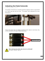
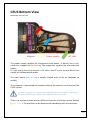
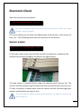
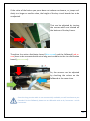
CEUS Service Manual Version 2.0 L. Bösendorfer Klavierfabrik GmbH Bösendorferstraße 12, A-1010 Wien [email protected], www.boesendorfer.com Telefon: +43 (1) 504 66 51-0, +43 (1) 505 35 18 Contents CEUS SERVICE BASICS ...................................................................................................................... 2 REMOVING THE HAMMER SENSOR RAIL .................................................................................. 3 REMOVING THE ACTION ................................................................................................................. 4 MOUNTING THE HAMMER SENSOR BAR ................................................................................... 5 ADJUSTING THE STOP-RAIL ......................................................................................................... 6 ADJUSTING THE SOLENOIDS ......................................................................................................... 7 ADJUSTING THE PEDAL SOLENOIDS........................................................................................... 9 CEUS BOTTOM VIEW ..................................................................................................................... 10 ELECTRONIC CHECK ...................................................................................................................... 11 THE MAIN BOARD .......................................................................................................................... 14 CALIBRATION .................................................................................................................................. 15 CHANGING THE SYSTEM BATTERY OF CEUS PC .................................................................. 20 BIOS SET UP OF CEUS PC.............................................................................................................. 21 1 Kapitel: CEUS Service Basics Please read the warning notices of the CEUS user manual (page 5-9) carefully. Before you start working with the CEUS, please be sure that the power switch is turned off! Switch the CEUS off and wait for approximately 30 seconds, before you start to disassemble the grand. The fallboard can be removed without using any tools, because the supply of electricity comes from the side attachment for the fallboard (yellow circle). The action is connected by only one cable to the CEUS system and can be removed (red circle). Never plug or unplug the cable whilst the system is switched on! If you have finished your work on the CEUS and the integrated display of the fallboard does not work, you may have forgot to plug in the connection cable. In this case, switch the CEUS off, wait for 30 seconds and plug the connection cable in. 2 Kapitel: CEUS Service Basics Removing the Hammer Sensor Rail Tool: Screwdriver PH 1x8o Make sure that the system is disconnected from power! Pull the action out of the grand carefully! After pulling out the action, you will see the Hammer Sensor Rail. On it there are the circuit boards with the soldered light sensors. The flags, which are mounted on the hammer shanks, have to pass the light sensor exactly in the middle. If the flag passes the sensor, the sensor light is blocked by the metal flag, set free and interrupted again. During this short time frame the hammer speed is measured. If the hammer sensor rail has to be removed, disconnect the two white cables of the circuit board in the bass section (red circle/picture, page 4). Pull the black interlock gently away from the connector. Now the cable can be removed. 3 Kapitel: Removing the Hammer Sensor Rail Remove the screws (yellow circle) with a PH 1x80 screw driver. Lift the unscrewed hammer sensor bar to the front of it and unhook it (green circle). Removing the Action In principle, the action can be simply removed like any other Bösendorfer action. The CEUS action is connected by two cables (blue circles) to the keyboard. Please unplug them first! When you put in the action again, please make sure that both ends of the cable, which connect the distribution circuit board of the action with the key sensor boards, are completely connected. One plug connects the distribution circuit board of the action to the key sensors. The smaller plug (Irda print), transfers the data information of the fallboard. 4 Kapitel: Mounting the Hammer Sensor Bar Tool: Screw driver PH 1x8o Re-hook the hammer sensor bar and screw it slightly into the hammer rail, and connect the circuit board of the bass with the other boards. Insert the cable parallel and fully into the plug connection! Risk of short-circuit! Correct Wrong! Check if the flags pass the sensors in the middle! Tighten the hammer sensor bar gently and make sure that all flags pass through the middle of the light sensors. After tightening the screws please make sure again that all the flags go through the center of the sensor. If the flags do not pass the sensor in the middle, loosen the screws slightly and move the hammer sensor bar a little. 5 Kapitel: Mounting the Hammer Sensor Bar Adjusting the Stop-rail Tool: Screw driver 3.o The stop-rail is mounted under the whippen rail of a CEUS action. It must be set so that there is a gap of 1mm between the upper edge of key and stop-rail, when the key is pushed down hard. If you have changed the key height or depth of touch, check the gap of the stop rail before and after the operation. Before a more extensive regulation of the action, it is recommended to screw in the stop rail. So any unwanted limit of the key movement can be prevented. There are 4 adjustment screws in every section. If the stop rail has to be adjusted over a bigger distance, please turn the screws in a little bit at a time, evenly and in sequence. 6 Kapitel: Adjusting the Stop-rail Adjusting the Solenoids Tool: Flat spanner (metric) 5.5 and 7 To ensure perfect reproduction, the gap between solenoid and key has to be as small as possible. Remove the protective covers to have free access to the Solenoids. If the back posts interfere with removing the cover, loosen the mounting screws and remove the back posts. Check the gap between magnet and key by tapping the core of the magnets. This step is like adjusting the capstan to the whippen of an upright. No gap but also no pressure on the key. Mark the keys which have a gap above the key, pull out the action and set the adjustment cap of the solenoids to the correct height. Use a metric flat spanner (5 and 7) to loosen the distance cap. Please loose the distance cap/nut of the solenoids carefully! The guide rod may bend! 7 Kapitel: Adjusting the Solenoids If solenoids are set too high, you will notice a slight movement of the keys when pushing the action in. An unequal Hammer Head line can also be caused by a high-set solenoid. As a control, pull the core of the magnet down and keep tabs on the key. If the solenoids are set too high the key will move up. Calibrate the system after adjusting the solenoids! See chapter „Calibrate“ 8 Kapitel: Adjusting the Pedal Solenoids Tool: Flat spanner (metric) 11 and 13 The pedals of the CEUS are moved by powerful magnets, which are connected by a steel rope with the lyre bars. The pedals can be adjusted like every Bösendorfer. Check if the steel ropes are slightly stretched. If the ropes are too loose, they can be stretched by turning the adjustment plate. Adjustment plate After adjusting the pedals, they have to be calibrated! See chapter „Calibrate“, page 18. 9 Kapitel: Adjusting the Pedal Solenoids CEUS Bottom View Model 280, without cover Magnets PC/HDD Power supply AC inlet The power supply supplies all components with power. A 48-volt line is connected to a copper bar (red arrow). The copper bar supplies the solenoids with power. A 5 volt line to the circuit boards, a 12-volt to the PC and a second 48-volt line supply the fallboard with power. The main board (blue arrow) is usually located next to the pc (depends on model). The computer is connected via network cable to the central circuit board of the CEUS system. The CEUS - computer is a conventional PC with SSD drive and a Windows 7 operating system. If PC problems occur, a monitor and a keyboard can be connected. There is a communication box for MIDI and Internet connection at the bottom (green arrow). The position can be determined individually with the customer. 10 Kapitel: CEUS Bottom View Electronic Check Open the service menu and go to: Value for keys/solenoids : yes? OK For more information about the service menu please see the CEUS User Guide (chapter "Service" page 42). This menu allows you to check the adjustments of the sensors, the function of keys, etc… The following menu items are relevant for the service: Sensor values Key: 21 Sensor value : 2252 In this menu, the sensor value of each key can be inspected. It measures the distance of the bottom edge of the keys to the light sensors. The light sensor is located directly under the capstan point of every key. The sensors send and receive light to determine the accurate position of every key. If a key is pressed, it moves away from the sensor and the reflected light gets weaker and therefore the value is less. The system does not differ between pedals and keys. The pedals are listed as key 109, 110 and 111. 11 Kapitel: Electronic Check If the value of the button you press does not reduce continuous, or jumps suddenly to a larger or smaller value, the height of the key circuit boards has to be readjusted. That can be adjusted by turning the screws which are located on the bottom of the key frame. Therefore the action distributor board (blue arrow) and the fallboard (red arrow) have to be connected with extra long service cables to the rim distribution board (green arrow). So, the sensors can be adjusted by checking the values on the fallboard at the same time. Since the long service cable is not commercially available, we will send one to you if needed. For the fallboard, please use an USB cable with an A / connector - mini B / connector. 12 Kapitel: Electronic Check Sensor Values, linear Key: 21 0 ms Time: xxxxxxxx This menu shows the key movement in 0 – 250 steps. If a key is pressed the value has to increase steadily going from 0 to max. 250. Each time you start the CEUS, the system sets this value automatically to 0. Small, climatic irregularities can be resolved. Hammer Head Sensors Head: 21 10456 _H_ HV 32 When the flag passes the sensor, the sensor light is blocked by the metal flag, set free and interrupted again. During this short time frame the hammer speed is measured. In this menu you can check the hammer head sensors. The value after the arrow is the internal velocity value, which changes after every stroke. The note „_H_“ does not necessarily appear on the display. If the sensor interrupted a „B“ appears next to the „H“ you can hear an alert. For example: Head: 46 35666 _HB HV 65 If a constant alert sounds while this menu is open, it means that a sensor is interrupted or is broken! 13 Kapitel: Electronic Check The Main Board The main board is the “heart” of the CEUS system. By using a jumper, sections, or the whole system can be reformatted. After a circuit board change, for example. Do a formatting only after consulting a Bösendorfer CEUS technician! Red circle : Jumper I = formatting all circuit boards, except main board Yellow circle : Jumper A = Service (keep service menu open) Pink circle : Jumper C = reset of the whole system Red arrow : Connection to pedal print/ Key drive unit. Blue arrow : MIDI. Orange arrow : Network to PC. Green arrow : 5V - Power inlet. 14 Kapitel: The Main Board Calibration CEUS has several steps to calibrate the system, which can be executed individually. You can start and stop the calibration process at any key, except during the “Balance keys” calibration. Please read the instructions carefully before starting the calibration! By pressing the GIS next to the grand sign, the service menu can be unlocked. More information about open the service menu is in the CEUS User Guide (chapter „Service“ on page 42). Overview: Calibrate keypress Calibrate keys • Define solenoid and keynumbers • Manual high calibration • Manual low - calibration • Manual key scanning • Manual calibration of the keys • Fine calibration of the keys • Rough calibration of the keys • Balance keys • Calibrate lost motion • Calibrate hammer vel.: loud • Calibrate hammer vel.: medium • Calibrate hammer vel.: soft • Calibrate hammer vel.: all The relevant calibration steps of a CEUS service are coloured black. 15 Kapitel: Calibration Velocity: If no extensive work has been carried out on the action, a calibration of the hammer velocity is sufficient. Open the menu: Calibrate keypress yes? OK You have the option to calibrate all 6 velocity steps at once (loud, medium and soft), or individually. In the private field, it is not essential to calibrate the hammer velocity “loud”. Choose the menu item by pushing the brass buttons sired menu item appears on the display. or , until the de- Calibrate hammer vel.: soft Push the brass button and choose the first key. Model 290 – Key 12 Model 225 – Key 17 Model 170-214 – Key 21 After pressing the button again, the system starts to calibrate the CEUS. Pease check the function of the hammer sensors, before calibrating the hammer velocity! (See Page 14) 16 Kapitel: Calibration Calibration steps after working on the Action If adjustments of the action or the solenoids have been done, the „Fine calibration of the keys“ (menu „Calibrate Keys“) and after that „Balance keys“ (menu „Calibrate keypress“) has to be execute. The pedals are calibrated automatically together with the keys (No.109/110/111) Open the menu: Calibrate keys Choose the menu item: Fine calibration of the keys Choose the first key and push the button. The system starts to calibrate. The „Fine calibration of the keys“ has to be executed before „Balance keys“. Then start to „Calibrate hammer vel.: xxxx“. Then go to: Calibrate keypress Choose the menu item: Balance keys During the calibration „Balance keys“, every solenoid pushes the key smoothly to level 10 of key movement. The number of the key which is calibrated, is shown on the Display. 17 Kapitel: Calibration Calibrating the Pedals If only the pedals have to readjusted, it is not necessary to do the fine calibration of all the keys. The Pedals can be calibrated separately. Therefor start the calibration process at key 109. Make sure that the steel ropes are in the guidance channel of the pulley! Please find more information about the service menu in the “CEUS User Guide”; chapter „Service“ Page 42. Go to the menu: Calibration of the keys Open the menu item: Fine calibration of the keys After pushing , the display shows: Select first key: 21 Choose the key number 109 by pushing the Select first key: Press brass button. 109 and the system start to calibrate the pedals. 18 Kapitel: Calibration Calibrating Lost Motion If any adjustments of the sustain pedal have been done, it is necessary to calibrate the lost motion of damper. Please go to the menu item: Calibrate keypress Push the button: Calibrate lost motion Press , the display shows: Move to lost motion ->OK w:xxx Push the sustain pedal till the dampers lift off. It is easier to press the pedal by hand to detect the point of the end of lost motion. Hold the position and press the The display shows: button: Calibrate lost motion The calibration is completed. 19 Kapitel: Calibration Change the System Battery of CEUS PC Tool: Screwdriver PH 1x8o If the display shows: ! System startup ! and it is frozen, an empty system battery could be the cause. Try to start the PC by hand (press the power button of the computer). If the system boots up after the manual start, the battery has to be changed. Disconnect the pc from the system (2 USB, 2 network cables, 1 power cable) and demount it. Loose the 6 screws and demount the cover. Change the battery (Type: CR2032) 20 Kapitel: Change the System Battery of CEUS PC BIOS Set Up of CEUS PC After changing the system battery the auto start function of the CEUS pc has to be set up again. Therefore please connect a monitor and a keyboard to the pc. Turn the pc on and press the “DEL” button to start the BIOS menu. Go to “Integrated Peripherals” and press „enter“. Go to “Super IO Device” and press ”enter”. Go to “PWRON After PWR-Fail”, press “enter”, set it to “On” and press „enter“. By pressing F10 the set up is stored. Set “Y” and press enter. 21 Kapitel: BIOS Set Up of CEUS PC