1
960 Technical Service Manual
CONTENTS
Introduction
How it Works
Relief Valve
Packing Box
Warranty
Parts Diagram
Pump Curves
1
1
2
3
4
5
6
INTRODUCTION
DANGER
Before starting pump, be sure all drive
equipment guards are in place.
Failure to properly mount guards may
result in serious injury or death.
This manual deals exclusively with the 960
series Pumps. Included in this manual are
most general issues pertaining to this
pump. For special applications not covered
in the manual, please refer to the factory or
authorized service personnel.
HOW IT PUMPS
Pumping: The pumps operate equally in
clockwise or counter clockwise rotation.
The rotational direction determines which
port is suction and which discharge. Figure
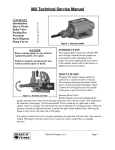
2 shows how the liquid travels the outside
of the gears to get from inlet to outlet.
Pressure Relief Valve:
BearCat Pumps are positive displacement
pumps and must have some sort of pressure protection. This may be a relief valve mounted to
the backside of the pump. The Pressure Relief Valve is made up of a plate that is held
against a port by a spring. The spring tension can be adjusted for varying pressures. When the
pressure exceeds the adjusted amount, it pushes the plate (Inner Poppet) back, allowing the
liquid to flow back to the inlet side of the pump.
If a pump is rotated in reverse of normal operation, the end plate with the relief valve must be
rotated 180 degrees. Pressure relief valves cannot be used to control flow or regulate
pressure.
BearCat Pumps, L.L.C.
Page 1
960 Technical Service Manual
Item
Description
1
RV Housing Box
2
Inner Poppet
3
Outer Spring
4
Inner Spring
5
Outer Poppet
6
Cap O-ring
7
Adjuster Cap
8
Bolt O-ring
9
Adjuster Lock Nut
10
Pressure Adjuster Bolt
11
Inlet Cap
RELIEF VALVE
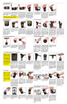
It may become necessary to
access the inside of the pressure
relief valve. If the Relief Plate is
removed for repairs, be sure to
replace it in the proper
orientation in relation to the
outlet port. (See Figure 6)
2.
3.
4.
5.
REMOVAL:
1. Measure the Pressure adjuster
bolt distance from back of the
Cap to the end of the Adjuster
Bolt before proceeding.
Release spring compression by loosening the Adjuster Lock Nut and Bolt.
Remove ½ bolts securing the Adjuster Cap. Remove items 2-6 (Fig 6). Clean and inspect.
Re-assemble in reverse order.
Set Adjuster Bolt to distance measurement established in step 1.
DANGER
Before servicing any BearCat Pump liquid chamber or Relief Valve ensure that:
• Pressure inside pump has been completely vented through appropriate openings or connections.
• The drive system has been locked out so that it cannot be started while work is being done.
• Sufficient time has expired for the liquid to cool sufficiently inside the pump. Observe any Material
Safety Data Sheets (MSDS) for the liquid to be sure these precautions are understood.
Failure to follow the above listed precautionary measures may result in injury or death.
BearCat Pumps, L.L.C.
Page 2
960 Technical Service Manual
Item
DANGER
Before servicing any BearCat Pump liquid
chamber or Relief Valve ensure that:
•
•
•
Pressure inside pump has been
completely vented through
appropriate openings or
connections.
The drive system has been locked
out so that it cannot be started while
work is being done on the pump.
Sufficient time has expired for the
liquid to cool sufficiently inside the
pump. Observe any Material Safety
Data Sheets (MSDS) for the liquid
to be sure these precautions are
understood.
Failure to follow the above listed
precautionary measures may result in injury
or death.
Description
1
½ Studs, Nuts
2
Gland Clips
3
Packing Gland
4
Packing Set
5
Packing Washer
6
Jacketed Shaft Plate
PACKING BOX
Periodic service of the packing seal can improve
pump performance as well as extend service life.
Packing Replacement:
1. Remove Clips and Gland.
2. Remove old packing. (Use a packing hook, or Thandle cork screw tool). Be sure to remove ALL
packing.
3. Install new packing one at a time. Stagger the split
of each ring at 180º intervals. Lubricate the rings
with oil or grease to aid in assembly. A length of
pipe or tubing will help in seating the packing
rings.
4. Install the Packing Gland and Nuts. The gland
must enter the stuffing box at least one-eighth of
an inch after tightening the Packing Gland Nuts.
Be sure the glands are tightened evenly. Tighten
Packing Nuts to about 1-1/2 turns past figure tight.
DO NOT over tighten; further adjustment should
be done while pump is operating.
BearCat Pumps, L.L.C.
Page 3
960 Technical Service Manual
MAINTENANCE
The 960 series pumps are designed for long, trouble free service under an extended variety of
applications with minimal maintenance, however, the following should be considered.
1. PACKING ADJUSTMENT: New packed pumps generally require some initial packing
adjustment to control leakage as packing is broken in. DO NOT over-tighten the packing
gland. After initial adjustment, occasionally inspect for further adjustment, and or packing
replacement.
2. PORT FLANGE: Re-tighten the port flanges after initial heat-up, as the gasket material
tends to soften and leaks can develop. Inspect connections frequently during first few days
of operation.
3. STORAGE: If the pump is to be stored for an extended length, a light coat of lubricating
and preservative oil should be applied to the internal parts.
DANGER
Before starting pump, be sure all drive
equipment guards are in place.
Failure to properly mount guards may
result in serious injury or death.
WARRANTY
BearCat Pumps warrants all products manufactured by it to be free from defects in workmanship or
material for a period of one year from date of shipment.
Due to the inconsistencies in blend formulas and operating methods, BearCat Pumps does not assume
responsibility for pump wear life. After material has entered a pump, all warranty claims will be
determined by factory-authorized personal.
BearCat Pumps assumes no liability for consequential damages of any kind and the purchaser, by
acceptance of delivery assumes all liability for the consequences of the use or misuse of BearCat
products by the purchaser, his employees or others. BearCat Pumps will assume no field expenses for
service or parts unless authorized by it in advance.
This is BearCat’s sole warranty and is in lieu of all other warranties, expressed or implied, which are
hereby excluded, including in particular all warranties of merchantability or fitness for a particular
purpose.
BearCat Pumps, L.L.C.
Page 4
960 Technical Service Manual
Item
Description
Part Number
Item
Description
Part Number
1
Gear Set
GER-83680
13
Castle Nut (2)
FAS-88678
2
Drive Shaft (short)
PTM-83643
14
Cap O-ring
RNG-83614
2B
Drive Shaft (long)
PTM-83644
15
Domed Bearing Cap (2)
HSG-83605
3
Idle Shaft
PTM-83640
16
Packing Housing
HSG-83611
4
Housing Body
HSG-83601
17
Blind Bearing Cap
HSG-83606
5
Port Gasket (2)
RNG-89071
18
Packing Washer
N/A
6
End Plate Gasket (2)
RNG-69993
19
Packing Set
SET-83695
7
End Plate (2)
HSG-83603
20
Packing Gland
BRK-83689
8
Piston Ring Bracket (4)
MSC-83666
21
Retainer Clip
BRK-83725
9
Piston Ring (4)
FAS-83614
22
½-13 x 1.5 Hex Bolt (16)
N/A
10
Bearing (4)
PTM-83612
23
3/8-16x1.75 SHCS (6)
N/A
11
Belleville Washer (2)
N/A
24
3/8-16x1.25 Hex Bolts (4)
N\A
12
Cotter Pin (2)
GER-64502
25
1/8 NPT Grease Zerk (4)
N/A
BearCat Pumps, L.L.C.
Page 5
960 Technical Service Manual
960 PUMP CURVES
BearCat Pumps, L.L.C.
Page 6