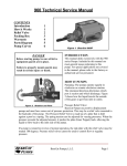
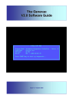
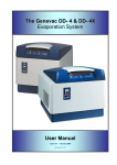
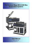
1
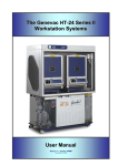
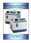
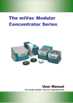
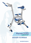
The Genevac DD- 4 & DD- 4X
Evaporation System
User Manual
Issue 2.7 – May 2008
Part Number 10-1471
Genevac DD4 Evaporating System
Contents
1
Introduction
Amendment Control Form
1.1
Safety symbols
3
4
4
2
System description and options
5
3
3.1
3.2
3.3
3.4
3.5
3.6
Scope of delivery and installation
Checking the delivery
Arranging commissioning
Training
Positioning the evaporator
Fitting a remote condenser
Fitting a vacuum pump
6
6
6
6
6
7
7
4
4.1
4.2
4.3
4.4
4.5
4.6
4.7
Safety
Rotor changing
To remove the rotor:
To fit the rotor:
Safe loading for swing rotors
Safe loading for fixed angle rotors
Maintenance of rotor, swings and holders
Lid operation
Sample traceability
Limitations of use
8
8
8
8
9
10
11
12
12
12
5
5.1
5.2
5.3
Getting started
How to switch on the pump
How to switch on the evaporator
Using the keypad
13
13
13
13
6
6.1
6.2
6.3
Options
Condenser defrost
Dri-Pure
Rotors
18
18
19
19
7
Technical data
20
8
EC Declaration of Conformity
22
9
Safety
22
10
Warranty Statement
22
11
Useful information
24
These instructions are subject to change without notice.
No part of these instructions may be reproduced in any form or
be processed, duplicated or distributed by electronic or optical
means without the written permission of Genevac Limited.
All rights reserved. © Genevac Limited
These operating instructions should be read before you use the
Genevac DD4 Evaporating System.
Keep them near the system for easy reference.
Your attention is drawn in particular to Section 4 Safety.
10-1471 Issue 2.7 – May 08
Page 2 of 24
Genevac DD4 Evaporating System
1
Introduction
The Genevac DD4 range of evaporation systems are
state-of-the art and represent a significant step
forward in evaporation technology for the R&D
laboratory.
Drawing on extensive experience in the drug
discovery field, the DD4 systems are designed to
provide very high performance coupled with ease of
use.
As you will discover, the system is simple to set up,
easy to operate and very flexible.
The status of the system is displayed and controlled
on a single keypad, display module indicating the run
time, the vacuum, rotor temperature and chamber
temperature on digital displays.
Simple to use up-down controls enable the run time,
rotor and chamber temperatures to be set in an
instant and single push buttons set the other
functions.
This manual will guide you through the start up
requirements, set up needs and operation of the
system to facilitate the most efficient procedure to
protect your product’s integrity and to ensure
optimum performance at all times.
10-1471 Issue 2.7 – May 08
Page 3 of 24
Genevac DD4 Evaporating System
Amendment Control Form
Revision
Number.
Issue and Reason for Change
Date Issued
2
3
4
5
Introduction of Amendment Control Form, Introduction of Genevac
ATEX statement – Page 22, Inclusion of DD-4X specifications.
Introduction of Genevac Combustible Solvents Statement - Page 22.
Changes to EC Declaration of Conformity, Introduction of Scroll Pump.
Introduction of Warranty Statement
Change to EC Declaration of Conformaty.
18 December 2003
01 March 2004
26 April 2004
21 September 2004
6
Add Maintenance of Rotor swings and Sample Holders
9 April 2008
1
1.1
01 October 2003
Safety symbols
The following safety symbols are used throughout
this manual.
The definitions and scope of each symbol is as
described below.
WARNING
THIS SYMBOL WILL INDICATE HAZARDS THAT
CAN LEAD TO SERIOUS MATERIAL DAMAGE OR
POTENTIAL SERIOUS INJURY.
Caution
This symbol will give information about hazards
that can be harmful to your health or lead to
material damage.
Note
This symbol will give information about technical
requirements which if not followed, can lead to
malfunctions, inefficiency and reduced productivity.
IMPORTANT
THIS SYSTEM MUST BE
EARTHED – SEE PAGE 21
10-1471 Issue 2.7 – May 08
Page 4 of 24
Genevac DD4 Evaporating System
2
System description and options
The basic DD4 Evaporation System is comprised of
an evaporation chamber and rotor.
System
Status
Run Time, Vacuum and Temperature Displays
The diagram below shows the fixed angle rotor
version, combined with the optional, in-built
cryopump-condenser unit.
Vacuum is provided by either the Scroll Pump or the
CVP vacuum vapour pump, although other types of
vacuum pumps can be used.
The control of chamber, bucket and sample
temperature, vacuum ramping rate, chamber
pressure, rotor speed and run time are all handled by
an onboard microprocessor.
The display-keypad enables the user to change the
parameters quickly and easily and displays the
status of the system in an uncomplicated and easily
assimilated manner.
Start/Stop
Controls
Run Time
Modes
Aquaspeed and other
functional controls
The DD4 incorporates the RotoGuard infrared
temperature detection system, which monitors and
controls the maximum temperature of the sample
rotor.
The system also incorporates the Aquaspeed control
system to increase the evaporation rates with water
and aqueous solvent mixtures.
When selected, Aquaspeed controls the system
pressure to prevent water from freezing and thus
increases evaporation rate.
Lid
Vacuum port
Coolheat lamps
Solid rotor
Keypad / display
Condenser inlet
Condenser
Lid release
switch
Rotor assembly
Chamber
Condenser and
chamber drains
ON / OFF switch
10-1471 Issue 2.7 – May 08
Page 5 of 24
Genevac DD4 Evaporating System
3
Scope of delivery and installation
You will have purchased your system with or without
the option of commissioning by Genevac personnel
and possibly, without the option of a Genevac
vacuum pump and integral condenser.
Reference will be made in the following notes to the
installation procedures required to cover these
options.
On delivery, it is advisable to unpack your system at
the point of receipt, to ease the movement of the
component parts to the point of use.
3.1
Checking the delivery
Check the contents of the delivery as soon as
possible against the delivery note and notify
Genevac Ltd immediately of any missing or
damaged parts. (Refer to section 10 for contact
details).
3.2
Arranging commissioning
If your system is to be delivered separately, Genevac
Ltd will contact you prior to the delivery, to agree a
date to commission your system.
3.3
Training
Commissioning will normally include training in the
basic operation of the System. Further in house
training is recommended to fully exploit the flexibility
of the system.
THE DD4 EVAPORATOR MUST NOT BE
OPERATED BY PERSONNEL WHO LACK THE
TRAINING OR PROFESSIONAL EXPERIENCE TO
COMPREHEND THE HAZARDS THAT CAN ARISE
WHEN USING THE SYSTEM.
Personnel without such training require thorough
instruction. These operating instructions should form
the basis of this instruction.
3.4
Positioning the evaporator
POSITION THE EVAPORATOR AT LEAST 300 MM
AWAY FROM THE EDGE OF A BENCH AND THE
SAME DISTANCE CLEAR OF BREAKABLE
OBJECTS OR AREAS WHERE ENTRAPMENT
COULD OCCUR.
10-1471 Issue 2.7 – May 08
Page 6 of 24
Genevac DD4 Evaporating System
IF THIS POSITIONING REQUIREMENT
IS
IMPRACTICAL
THEN
THE
EVAPORATOR SHOULD BE BOLTED
TO THE BENCH OR TROLLEY, BY ITS
FIVE MOUNTING FEET, USING M10
X150 HEX H.T. BOLTS ZINC (SC1130).
GENEVAC SHOULD BE CONSULTED
FOR ADVISE ON ANY OTHER
POSITIONAL REQUIREMENTS.
Chamber
Condenser
Pump
3.5
Fitting a remote condenser
The connecting relationship of the
chamber, condenser and vacuum pump
is as shown.
The connection for your remote
condenser is located at the rear of the
evaporator.
Connect your condenser to the
evaporator chamber using a suitable
Kline flange fitting.
It is recommended that a heated inlet
tube is used to connect the chamber to
the evaporator, to prevent solvent from
condensing in the tube.
Please consult Genevac Sales for
details of the range of heated inlet tubes
available.
3.6
Fitting a vacuum pump
If your evaporator has an integral
condenser, the connection for your
vacuum pump is located at the rear of
the evaporator.
Connect your vacuum pump to the
evaporator using a suitable connecting
pipe and Kline flange fitting.
If a Genevac pump has been supplied
with your evaporator, the connecting
pipe, fittings and power control lead will
also be included.
Connect the power and control lead
between the pump and the socket on the
rear of the chamber.
If a CVP pump has been supplied, it must have an adequate supply of cooling air and
the hot outlet must have at least 300 mm of space beyond the hot air grille in the pump
base. It should not be placed in a cupboard without special precautions to ensure
adequate cooling.
If a Scroll pump has been supplied then it must not be moved between systems as the Scroll pump
will only function correctly on a Genevac Evaporator that has been upgraded to work with the Scroll
pump.
Consult Genevac Service for advice in such cases.
10-1471 Issue 2.7 – May 08
Page 7 of 24
Genevac DD4 Evaporating System
4
Safety
BEFORE OPERATING THE SYSTEM, IT IS
IMPORTANT
THAT
THE
FOLLOWING
NOTES ARE READ TO ENSURE THAT THE
IMPLICATIONS TO THE SAFETY OF
PERSONNEL OPERATING THE SYSTEM
AND FOR THE PROTECTION OF SAMPLE
INTEGRITY ARE UNDERSTOOD.
•
There are important safety and
operational considerations to be
made when positioning the
system.
Samples in the chamber are subjected to
accelerations of up to 500G with a maximum
load capacity of 1.5 kg per swing.
•
Refer to Section 9 Technical Data
for recommended clearances
The following precautions should therefore
always be observed.
4.1 Rotor changing
The DD4 is designed to offer different rotors to
be fitted to optimise performance.
To remove the rotor:
1.
Remove samples and holders where
fitted.
2.
Undo the retaining nut, using Thandle until the rotor can be lifted out
3.
Lift using T-handle.
To fit the rotor:
1. Using T-handle lower rotor carefully
into the chamber.
2. Tighten the retaining nut using the Thandle.
Note that if retaining nut rotates freely, then
rotor has not engaged correctly
3. Lift 50mm (2”) using the T-handle.
4. Turn rotor and repeat 2 and 3 above.
5. Tighten the retaining nut securely.
6. Manually rotate the rotor to ensure that
it runs freely.
10-1471 Issue 2.7 – May 08
Page 8 of 24
Genevac DD4 Evaporating System
4.2 Safe loading for swing rotors
When using a swing rotor ensure that “FIXED
ROTOR” option is deselected on control panel, if
this option is available.
Before loading samples,
retaining nut is secure.
1.5 kg MAX including tubes, solvent,
sample, sample holder and swing
check
that
rotor
Never exceed the maximum load capacity of 1.5 kg
per swing.
Balance pairs of sample holders that are loaded
opposite each other to within 10g (approximately).
Locate tubes correctly in tube holders.
Locate sample blocks correctly in sample swings.
Load two or four tube holders in opposite and
balanced configurations.
Distribute tubes in sample holders symmetrically.
Rotate the rotor by hand after loading and check that
all tube holders and plates are correctly located
before starting a run and before re-starting an
interrupted run.
Do not load tubes or vials into sample holders other
than those types that have been approved by
Genevac Ltd.
Do not use sample holders that have not been
supplied with system without consulting Genevac
Service.
Genevac Ltd will accept no
responsibility for any loss or damage
incurred by improperly or excessively
loaded rotors.
10-1471 Issue 2.7 – May 08
Page 9 of 24
Genevac DD4 Evaporating System
4.3 Safe loading for fixed angle rotors
Ensure that “FIXED ROTOR” option is selected
on control panel.
Before loading samples,
retaining nut is secure.
check
that
rotor
Interchangeable fixed angle rotors are available for
various tube diameters.
TUBE LENGTH SHOULD NOT EXCEED THE
MAXIMUM SPECIFIED ON THE LABEL.
The rotors are configured with concentric rings of
tube holders with the capacities specified on the
rotor label.
Use only the tubes specified on the label; the tube
should slide freely into the rotor.
Your system will operate with up to 85g of imbalance
and it is therefore important to load the solid rotors in
systematic manner to ensure that this level is not
exceeded.
Generally each tube should be balanced with a
similar tube diametrically opposite.
How critical the loading should be, will depend on the
size of tube and the volume and density of the
solvent being loaded.
For instance, a 150 x 24 mm tube loaded with 30 ml
of water, weighs approximately 72g.
Fixed rotor examples
The tube with the same volume of chloroform would
weigh 86g which, would be enough to imbalance the
rotor if loaded singly or in an unsymmetrical manner.
If a tube is loaded here.
Then also load a similar tube here.
Always load the rotor in a symmetrical and
balanced manner.
10-1471 Issue 2.7 – May 08
Page 10 of 24
Genevac DD4 Evaporating System
4.4 Maintenance of rotor, swings and sample
holders.
Regular inspection and maintenance of swings and
sample holders should be performed at least
monthly. The following inspection routine is
mandatory following any tube breakage or solvent
spillage. Never use wet swings, holders or rotors in
an evaporator.
Inspection:
Visually inspect holders each month. Debris should
be cleaned off, especially any in the sample holder
wells as this may lead to glassware breakage. The
number one cause of repeat glassware breakage is
glass fragments from a previously broken tube.
Sometimes the sample sticks the glass fragments to
the inside of a holder well, and can be difficult to
remove. Residual solvent / sample - should be
cleaned off.
Superficial surface damage (e.g. scratches) will not
affect the performance of a rotor, holder or swing. If
there is structural damage (a bend of deformation) of
any part of a rotor, swing or holder - do not use contact Genevac for evaluation.
Cleaning:
Loose dirt or debris can be removed using a brush
and / or airline. Adhered dirt / debris or sample /
solvent residue should be cleaned off using
methanol or acetone, soak swings or holders if
required. Swings / holders should then be washed in
clean water and fully dried before use.
10-1471 Issue 2.7 – May 08
Page 11 of 24
Genevac DD4 Evaporating System
4.5 Lid operation
The lid is secured by an electromechanical catch that
is activated automatically to lock the lid.
Press the button on the front panel of the evaporator
to release the catch.
Note that you will be unable to open the lid whilst the
rotor is rotating.
Lift the lid past 45 degrees to ensure that it remains
in the open position.
Note that when the lid is near its closed position, it is
designed to close under its own weight.
46 Sample traceability
Each fixed angle rotor has a label that indicates the
tube number in each ring.
Whilst this will aid loading, it is recommended that a
separate log is kept of sample position when
dissimilar products are loaded.
Alternatively, use a suitable label to identify the
samples.
Note that labels can affect performance.
4.7 Limitations of use
Example of rotor label
10-1471 Issue 2.7 – May 08
Your DD4 evaporating system is unsuitable for use
under the following circumstances:
•
With strong mineral acids such as HCl and HBr
at any concentrations.
•
EVAPORATING
DIETHYL
ETHER
AND
SIMILAR LOW AUTO-IGNITION SOLVENTS
WITHOUT A GENEVAC INERT GAS PURGE
SYSTEM FITTED TO THE EVAPORATOR AND
PUMP.
•
For use as a pressure vessel.
Page 12 of 24
Genevac DD4 Evaporating System
5
Getting started
The following notes describe the basic start up, set
up and run instructions for your DD4 evaporating
system.
If a Genevac vacuum pump is fitted, the chamber is
powered from the pump and so it is only necessary
to connect the pump to a suitable mains power
supply.
5.1 How to switch on the pump
Connect the pump to the mains and switch on the
mains.
Switch the pump mains switch on as shown.
The system will not be available for use until the
vacuum pump has reached the correct operating
temperature (about 25 – 30 minutes for the Scroll
pump. This only occurs when the system is first
switched on, (5 – 10 minutes for the CVP).
5.2 How to switch on the evaporator
Switch the mains switch on as shown.
ALL LEDs will light to check operation.
The READY light will be illuminated in red, to
indicate that there is power to the evaporator.
Press START to power up the evaporator.
The vacuum pump and the condenser will start after
a short delay.
The READY light will remain red until the pump and
condenser
have
reached
their
operating
temperature. The Run Time indicator will display the
time left for the Pump Warm Up Time in MM:SS.
Amber indicates that the pump has reached its
operating temperature but that the condenser has
not yet reached its operating temperature.
The system is ready for use when the READY light is
illuminated green.
On power up, the RUN TIME, VACUUM, ROTOR
TEMP and CHAMBER TEMP will be illuminated.
5.3 Using the keypad
The DD4 keyboard controls and displays have been
designed for ease and simplicity in use.
10-1471 Issue 2.7 – May 08
Page 13 of 24
Genevac DD4 Evaporating System
Using and setting the timer
During a run the RUN TIME can display either the
elapsed time, E or the remaining time, R.
Press the up and down keys simultaneously, to
toggle between the elapsed and remaining times.
The timer has three different modes that are
accessed by pressing the MODE key.
The selected mode will be illuminated.
Using the TIMED mode
The TIMED mode is used when a predetermined run
duration is required with Coolheat.
The duration can be modified at any time prior to or
during a run.
To set the run duration in TIMED mode use the up
and down keys to input the desired run time.
Coarse setting is achieved by holding down either
key.
Fine setting is achieved by pressing either key once.
A maximum time of 99 hours 59 minutes and a
minimum time of 1 minute can be set. Elapsed or
remaining time can be displayed in this mode.
Using the NON-STOP mode
The NON-STOP mode will run continually with the
Coolheat facility enabled, until the STOP key is
pressed.
This mode is particularly useful if the evaporation
time for a particular solvent or solvent mixture is not
known. Only elapsed time is displayed in this mode.
Using the 2 STAGE mode
The 2 STAGE mode is used when the Coolheat
facility is required for a predetermined period.
After this period has elapsed, the Coolheat facility
will be disabled and the system will continue to run at
full vacuum until the STOP key is pressed. Elapsed
or remaining time can be displayed during the first
stage of this mode, but only elapsed time during the
second stage.
10-1471 Issue 2.7 – May 08
Page 14 of 24
Genevac DD4 Evaporating System
This mode is particularly useful for lengthy
evaporation times, when it may be necessary to run
the system overnight.
Since the Coolheat facility will be disabled after
the predetermined period, sample temperature
may reach the temperature to which the chamber
has been set.
The VACUUM Display
The vacuum display indicates the absolute pressure
of the system in millibar (mbar).
As the vacuum pump evacuates the system, the
value will continually change, until the full vacuum
capability of the pump is reached.
The key below the vacuum display enables the
AQUASPEED function.
Using the AQUASPEED function
AQUASPEED has been developed to significantly
improve system performance when evaporating
water or water mixtures.
It limits the system
pressure to 8 mbar,
Press the AQUASPEED key to select this facility, the
lamp will illuminate.
This function can also be used simultaneously with
the optional DRI-PURE facility.
Using the Rotor temperature control
The maximum rotor temperature is monitored and
controlled by the RotoGuard infrared temperature
detection system.
The setting of this control determines the
temperature at which the Coolheat lamps are
disabled.
For instance, if the temperature is set at 30°C, the
Coolheat lamps will be turned off when RotoGuard
senses a temperature of 30°C.
Note that from power up, this control defaults to the
previous settings.
10-1471 Issue 2.7 – May 08
Page 15 of 24
Genevac DD4 Evaporating System
To change the setting, press both
simultaneously and the SET prompt will flash.
keys
Use the up and down keys to set the required rotor
temperature.
Hold the key down for coarse setting or press once
for fine setting.
The value will be accepted and the display will revert
to ACTUAL after a short period.
Press either key to display the set temperature at
any time.
The display will automatically revert to the actual
setting after a short period.
The temperature setting can be changed during a
run using the same procedure.
Using the Chamber temperature control
This control displays and controls the temperature of
the chamber.
If this is set above ambient, prior to a run, the run will
not start until the chamber temperature has
preheated to the set value.
Preheating will be indicated by the point between
hours and minutes on the RUN TIME display
flashing.
To change the setting, press both
simultaneously and the SET prompt will flash.
keys
Use the up and down keys to set the desired
chamber temperature.
Hold the key down for coarse setting or press once
for fine setting.
The value will be accepted and the display will revert
to ACTUAL after a short period.
Press either key to display the set temperature at
any time.
The temperature setting can be changed during a
run using the same procedure.
10-1471 Issue 2.7 – May 08
Page 16 of 24
Genevac DD4 Evaporating System
The STATUS indicators
The status of the system is indicated by the row of
lamps on the far left of the display.
When switched ON, the SYSTEM READY lamp will
be red and all other lamps will be off.
On pressing the START key, the displays will be
illuminated and the SYSTEM READY lamp will
remain red until the pump and condenser are ready.
Note that from cold, the Genevac vacuum pump will
take approximately 10 minutes to reach operating
temperature.
When the run commences (after preheat if required),
the ROTOR SPINNING lamp will be illuminated
green.
Note that the lid will not open whilst the rotor is
rotating.
If an excessive out of balance is detected by the
system, the green IMBALANCE lamp will be
illuminated and the run terminated.
In such cases, press the STOP button after the rotor
stops, this shuts down the evaporator.
Correct the source of the imbalance.
The Coolheat indicator lamp will be illuminated when
the lamps are on.
10-1471 Issue 2.7 – May 08
Page 17 of 24
Genevac DD4 Evaporating System
6
Options
There are a number of options available at purchase.
Four additional buttons on the control panel have
been provided for those options that can be selected
by the operator.
These currently are:
Using Condenser
•
Condenser defrost
•
Dri-Pure
•
Fixed Rotor
6.1 Condenser defrost
Where fitted the internal condenser requires minimal
maintenance.
Note: The condenser has a 2 litre capacity.
In most cases, for best evaporation performance the
condenser should be drained between each run.
However under certain circumstances it may be
more practical to be carried out every alternate run.
Note: Do not defrost if solvent does not freeze.
If high boiling point solvents are used e.g. DMF,
DMSO, it will be necessary to defrost the condenser
prior to draining.
Press the DEFROST key (to initiate the defrost
cycle). The lamp will illuminate red. On completion
of defrost cycle the lamp will turn green
If the “Condenser Core Temperature” option has
been purchased, the lamp turns green when the
temperature in the pot indicates that all solvents are
liquid. The condenser will remain at this temperature
until DEFROST is deselected and drained.
If the “Condenser Core Temperature” option is not
fitted the green lamp indicates 2 hours duration
complete. This is just an indication, the defrost
continues to heat the solvent, drain at the first
opportunity.
Without the “Condenser Core Temperature”
option fitted, the defrost is constantly ON when
selected. This may cause a build up of vapour in
the chamber which may be harmful when
opening the lid.
Before operating the drain valve plunger, ensure
that the chamber drain is connected to a suitable
container.
To drain, open the lid and lift the drain valve plunger
which opens the drain valve.
10-1471 Issue 2.7 – May 08
Page 18 of 24
Genevac DD4 Evaporating System
Using the DRI-PURE feature
6.2 Dri-Pure
DRI-PURE
reduces
the
vacuum
over
a
predetermined period, at the end of which the full
vacuum capability of the vacuum pump comes into
effect.
This feature is particularly useful in preventing
bumping, (the violent boiling of solvents), resulting in
solvents being expelled, which is a source of cross
contamination of samples.
Bumping can also cause products to be deposited on
the glass lenses of the Coolheat lamps, which
eventually results in breakages.
To select this feature press the DRI-PURE key, the
lamp will illuminate.
Note that during the DRI-PURE cycle, which is
approximately 40 minutes, the Coolheat function will
be disabled.
Rotors
6.3 Rotors
There are 2 types of rotor currently available, these
are:
•
Fixed angle
•
Swing
The “Fixed angle rotor” is fabricated with
individually angled holders to take test tubes and
vials.
Fixed angle rotor
The “Swing rotor” has pivoting buckets that take the
sample holders.
During the run as the rotor speed increases the
buckets swing up through 90°, returning to the
horizontal position as rotor speed decreases to stop.
For loading and changing rotors refer to previous
section.
Swing rotor
10-1471 Issue 2.7 – May 08
Page 19 of 24
Genevac DD4 Evaporating System
7
Technical data
Controls
Temperature control range
Temperature Accuracy
Temperature control resolution
Temperature control
Temperature control range
Chamber temperature range
End of run
Ambient to 60°C
+/- 2.5°C
1°C
Infrared pyrometer
0°C to + 60°C
Ambient to 45°C
Run timer/continuous
Mechanical data
Max rotor speed
Max rotor speed
Max Force
Drive system
Operation imbalance
Max load (swing rotor)
IR lamps number
Weight
1300 standard
1800 Dri-Pure
300-500G
Direct
85g
4 x 1.5 kg @ 500G
2
95 kg (DD-4)
103 kg (DD-4X)
Vacuum system
Pressure display/resolution
Pressure control (Aquaspeed)
Dri-Pure
System ultimate vacuum
Auto vacuum vent valve
Vacuum chamber
Inert gas purge
0 -1200 mbar/1.0 mbar
8 mbar
Option
0.4 mbar
Yes
Cast aluminium with corrosion proof coating
External option
Vacuum pump - Scroll
Weight
Maximum vacuum
Flow rate
28 Kg
0.15 mbar (50Hz)
0.12 mbar (60Hz)
3.6 m3h-1
Vacuum pump - CVP
Weight
Maximum vacuum
Flow rate
52 Kg
0.15 mbar
3.6 m3h-1
Condenser data
Condenser temperature
Minimum
Maximum
Vacuum condenser capacity
Condenser chamber
Condenser drain valve
10-1471 Issue 2.7 – May 08
-40°C (DD-4)
-50°C (DD-4X)
+60°C
2.0 litres (DD-4)
2.3 litres (DD-4X)
316 Stainless steel
Stainless steel/PTFE
Page 20 of 24
Genevac DD4 Evaporating System
7
Technical data (continued)
Dimensions
Evaporator (W x D x H) (lid closed)
H (lid open)
Chamber diameter
535 x 642 x 583 mm (DD-4)
585 x 642 x 583 mm (DD-4X)
950 mm
458 mm
Condenser (W x D x H)
515 x 590 x 425 mm
Scroll Pump (W x D x H)
530 x 305 x 398 mm
CVP Pump (W x D x H)
540 x 290 x 405 mm
Electrical
Power supply
230V, 50Hz, single phase, 9A
208V, 60 Hz, single phase, 9A
Environment
The following figures apply:
Operating
Ambient Temperature:
Relative Humidity:
Altitude:
15°C to 30°C
10 – 60%
Sea Level to 1,600m
Storage
Ambient Temperature:
Relative Humidity:
Altitude:
10-1471 Issue 2.7 – May 08
-10°C to 60°C
10 – 80%
Sea Level to 12,000m
Page 21 of 24
Genevac DD4 Evaporating System
8
EC Declaration of Conformity
9
Safety
We Genevac Limited
Declare that this product:
Series II Evaporating System
Complies with the relevant Essential Health and
Safety Requirements of the European Machinery
Directive (89/392/EEC as amended by 91/368 EEC
and 93/44/EEC). The EMC Directive 89/336/EEC
and the Low voltage Directive 73/23/EEC.
Conformity is demonstrated by compliance with the
following specifications:EN 60204-1:1998, Safety of machinery– Electrical
equipment of machines-Pt 1 General Requirements
EN 249: 1992, Safety of machinery– Safety
distances to prevent danger zones being reached by
upper limbs.
EN 1088: 1996, Safety of machinery. Interlocking
devices associated with guards. Principles of design
and selection.
BS EN ISO 12100 pts 1 & 2:2003, Safety of
Machinery - Basic concepts, general principles for
design.
BS
EN
50082-1:
1998,
Electromagnetic
compatibility-Generic immunity standard.
BS EN 61010-2-020: 1995, Safety requirements for
electrical equipment for measurement, control and
laboratory use. Particular requirements for laboratory
centrifuges.
WARNING!
THIS SYSTEM MUST BE EARTHED
THIS EVAPORATOR IS A SAFETY CLASS 1
PRODUCT
ACCORDING
TO
IEC
CLASSIFICATION. IT MUST NEVER BE USED
WITH ANY INTERRUPTION TO THE SAFETY
EARTH CONDUCTOR. IT IS AN INSTALLATION
CATEGORY II PRODUCT AND IS INTENDED TO
OPERATE FROM A NORMAL SINGLE-PHASE
SUPPLY.
THIS EVAPORATOR HAS BEEN DESIGNED TO
BE USED IN A POLLUTION DEGREE 1
ENVIRONMENT (NO POLLUTION, OR ONLY DRY
NON-CONDUCTIVE POLLUTION).
ANY MAINTENANCE OR REPAIR OF THIS
PRODUCT SHALL BE CARRIED OUT BY
GENEVAC
PERSONNEL
(OR
APPROVED
REPRESENTATIVES OF GENEVAC) USING ONLY
APPROVED SPARE PARTS
Genevac and the ATEX Directive:
Please note that it remains the responsibility of the
user to consider any solvents being evaporated
within the context of the ATEX directive. If further
information is required, please contact your Sales
Representative or visit http://www.genevac.com/
Genevac Evaporators and Combustible Solvents
Please note it remains the responsibility of the user
to consider safety when evaporating any combustible
solvents and ensure the system is placed in a well
ventilated environment.
Genevac's position
regarding evaporation of such solvents, particularly
with respect to the European ATEX directive, is
available on our website or from your local sales
representative.
10-1471 Issue 2.7 – May 08
Page 22 of 24
Genevac DD4 Evaporating System
10 Warranty Statement
This product is guaranteed for period of 12 months from the date of delivery to site. In the unlikely event of any
defect arising due to faulty materials or construction resulting in system failure, the unit will be repaired free of
charge. This to include all labour and component costs incurred.
This warranty is subject to the following provisions:
1. System must be sited, installed and operated in accordance with operator instruction manual.
2. Unit only used for purpose it was sold, and in accordance with Genevac published compatible solvent
list.
3. Regular cleaning and preventative maintenance schedule to be adhered to as detailed in operator’s
manual.
4. Warranty does not cover accidental damage, misuse, modifications or inappropriate repair by untrained
personnel.
5. Warranty does not cover consumable items*
Failure to adhere to the above would result in the costs of repairs being charged.
* Consumable Items:
10-1471 Issue 2.7 – May 08
Sample Guard thermocouple probes
Cole Vacuum Pump oil
Control fuses
Page 23 of 24
Genevac DD4 Evaporating System
11 Useful information
Genevac Limited
The Sovereign Centre
Farthing Road
Ipswich
IP1 5AP
United Kingdom
Sales and Service Hotlines
Service Hotline: +44 (0) 1473 243000
If you need to contact Genevac for assistance, use
either the telephone or fax Hotlines given.
It will always help Genevac Service if you have the
serial numbers at hand for the components of your
system
If you need to contact Genevac Sales for information
on Service Contracts or products, use the telephone
or fax Hotlines given.
Alternatively, Email or visit our web site.
Sales Hotline: +44 (0) 1473 240000
Fax: +44 (0) 1473 461176
Email: [email protected]
Web site: http://www.genevac.com
Genevac Inc
711 Executive Boulevard
Suite H
Valley Cottage
New York
10989
United States of America
Sales and Service Hotline
(1) 845 267 2211
Fax (1) 845 267 2212
Email: [email protected]
10-1471 Issue 2.7 – May 08
Page 24 of 24