1
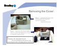
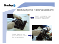
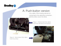
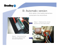
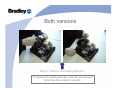
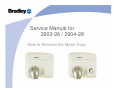
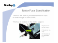
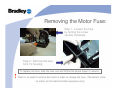
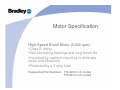
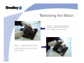
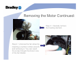
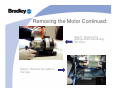
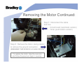
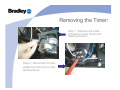
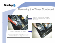
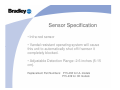
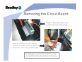
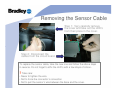
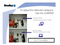
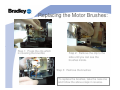
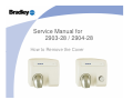
Service Manual for
2903-28 / 2904-28
How to Remove the Cover
Cover Specification
Cast Iron – White Porcelain
• 2903-28, Sensor Activation
(replacement P/N: P15-420)
• 2904-28, Push Button Activation
(replacement P/N: P15-421)
Reminder!
Disconnect power to the unit before
removing the cover
Removing the Cover:
Step 1: Unscrew the two lock
screws with the security
wrench provided.
(Part # P15-419)
Step 2: Remove the cover taking
care to avoid damaging the cover
or internal components.
!
Caution: For Automatic Dryers
Be sure to disconnect the sensor cord
connecting the cover to the base before removing!
Service Manual for
2903-28 / 2904-28
How to Remove the Heating Element
Heating Element Specification
• Undulated heating element
• Material: Winding in NICROM; Body in MICA
• Automatic resetting circuit breaker protects
against overheating.
Replacement Part Numbers: P15-424 for UL Models
P15-425 for CE Models
Reminder!
Disconnect power to the unit before
removing the cover
Removing the Heating Element:
Step 1: Unscrew the three
screws which connect the
two halves of the scroll.
Step 2: Separate both
parts of the scroll so that
you can work inside.
A: Push-button version
One cable of the heating element is
connected to the electrical connection,
and the other one to the timer.
Step 1: Disconnect the cable
from the electrical connection.
Step 2: Disconnect the cable
from the timer.
B: Automatic version
Both cables of the heating element are
connected to the circuit board.
Step 1: Remove the circuit
board from the base plate.
Step 2: Disconnect the
two white cables from
the terminal block.
Both versions
Step 3: Remove the heating element.
To replace the heating element, take the new one and
follow the above steps in reverse.
Service Manual for
2903-28 / 2904-28
How to Remove the Motor Fuse
Motor Fuse Specification
The fuse will blow to protect the motor in case
of over-voltage or short-circuit.
The fuse is located on the motor support.
Replacement
Part Number:
P15-432 for UL
only.
CE models do
not require a
fuse.
Reminder!
Disconnect power to the unit before
removing the cover
Removing the Motor Fuse:
Step 1: Loosen the fuse
by turning the screw
counter clockwise.
Step 2: Remove the fuse
from it’s housing.
!
To replace the fuse, take the new one and follow the above steps in reverse.
There is no need to remove the motor in order to change the fuse. (The photos show
no motor, but for demonstration purposes only).
Service Manual for
2903-28 / 2904-28
How to Remove the Motor
Motor Specification
High-Speed Brush Motor (5,500 rpm)
•Class B rating
•Self-lubricating bearings and long brush life
•Insulated by resilient mounting to eliminate
noise and vibrations
•Protected by a 2 amp fuse
Replacement Part Numbers: P15-422 for UL models
P15-423 for CE models
Reminder!
Disconnect power to the unit before
removing the cover
Removing the Motor:
Step 1: Unscrew the three
screws which connect the
two halves of the scroll.
Step 2: Separate both parts
of the scroll so that you can
work inside.
Removing the Motor Continued:
Step 3: Carefully remove
the heating element.
Step 4: Unscrew the fan wheel by
inserting a number 4 Allen wrench
and removing it. You can reach
the screw through the hole in one
of the fan blades.
Removing the Motor Continued:
Step 5: Remove the
springs which are binding
the motor.
Step 6: Remove the cable to
the fuse.
Removing the Motor Continued:
Step 7: Disconnect the cable
from the
• Circuit board (automatic version)
• Timer (push button version)
Step 8: Remove the motor, being careful
to remove the ground connection.
(REMEMBER THIS DRYER IS A CLASS I DEVICE)
To replace the motor, take the new one
and follow the previous steps in reverse.
Service Manual for
2903-28 / 2904-28
How to Remove the Push-Button Timer
Push-button Timer Specification
• Electro-mechanical timer
• 34 second timer
• The dryer turns off automatically after use.
Replacement Part Numbers: P15-426 for UL models
P15-427 for CE models
Reminder!
Disconnect power to the unit before
removing the cover
Removing the Timer:
Step 1: Remove the cable
connectors to the motor and
heating element.
Step 2: Disconnect the two
cables from the timer to the
terminal block.
Removing the Timer Continued:
Step 3: Loosen the screws
which are holding the timer to
the base.
Step 4: Remove the timer.
To replace the timer, take the new one
and follow the above steps in reverse.
Service Manual for
2903-28 / 2904-28
How to Remove the Sensor
How to Remove the Sensor Cable
How to Adjust the Detection Distance
Sensor Specification
• Infra-red sensor
• Vandal resistant operating system will cause
this unit to automatically shut off if sensor it
completely blocked.
• Adjustable Detection Range: 2-6 inches (5-15
cm).
Replacement Part Numbers: P15-438 for UL models
P15-439 for CE models
Reminder!
Disconnect power to the unit before
removing the cover
Removing the Circuit Board:
Step 1: Remove the circuit
board from the base plate.
Step 2: Disconnect the cables
coming from the heating element
and motor from the circuit board.
To replace the circuit board, take the new
one and follow the above steps in reverse.
Removing the Sensor Cable
Step 1: Very carefully remove
the cover and take out the LED’s
from their place in the cover.
Step 2: Disconnect the
cables from the circuit board.
To replace the sensor cable, take the new one and follow the above steps
in reverse. Do not forget to affix the LED’s with a few drops of silicon.
! Take care:
• Never to tighten the wire
• Not to force the connector’s connection
• Not to pull the sensor’s wire between the base and the cover.
To adjust the detection distance:
Use the JUMPER
A: High setting
Detection distance 8-10 inches
B: Low setting
Detection distance 4-6 inches
***The hand dryers are supplied with the
jumper on Low Setting.
Service Manual for
2903-28 / 2904-28
How to Replace the Motor Brushes
Motor Brushes Specification
The brushes have a theoretical life of 3000
hours. They are installed on the side of the
motor.
Brushes must be
changed if they are
shorter than 0.2 inches
Replacement Part Number:
P15-430
Reminder!
Disconnect power to the unit before
removing the cover
Replacing the Motor Brushes:
Step 1: Press the clip which
is covering the brushes
Step 2: Remove the clip to the
side until you can see the
brushes inside.
Step 3: Remove the brushes
To replace the brushes, take the new one
and follow the above steps in reverse.