1
1
111 Canfield Avenue • Randolph, New Jersey 07869 • 1-800-LANDICE • FAX 973-927-0630
L-Series
Home and Commercial Treadmill
Diagnostic and Service Manual
2003
Version C/D.2
For Technical Service Call 1-(800)-LANDICE
2
Service Manual Version C/D.2
Page 2-3
Table of Contents
SECTION 1- Introduction
Page 4
How to Use this Manual
Page 5-14
Replica Landice Warranty Cards and Warranty Policy
Page 15
Service Authorization Form
Page 16
Time Allotted for Repairs
Page 17-18
Tools Needed for Repairs
SECTION 2- Installation
Page 19-21
Safety Warnings
Page 22
Electrical Requirements for L-Series Treadmills
Page 23-25
Treadmill Assembly and Installation Instructions
Page 26
Treadmill’s General Dimensions
SECTION 3- - Parts Identification
Exploded View of L7 & L8/L9
Page 27
L8/L9 Bed
Page 28
L7 Bed
Page 29
L-Series Upright
Page 30
L-Series Motor Pan and Elevation Assembly
Page 31-34
Parts Listing
Page 35
Commercial Motor Pan Picture
Page 36-37
Commercial Motor Pan Wire Schematics
Page 38-39
LED lights on SCR
Page 40
SCR Upper Wire Harness Wiring Diagram
Page 41
Home Motor Pan Picture
Page 42
Home Motor Pan Wire Schematic
Page 43
PWM Voltage Readings and Paths
Page 44
LED Lights on PWM
Page 45
Relay Board Voltage Readings and Paths
Page 46
LED Lights on Relay Board
Page 47
Home Motor Pan Wire Schematic (PWM/Relay Assembly)
Page 48
Picture of PWM with Relay Assembly
Page 49
PWM Upper Wire Harness Wiring Diagram
Page 50
Executive Trainer LCD Wire Schematic
Page 51-54
L-Series Display Control Panels & Features
Page 55
Cardio Trainer / Executive Trainer Addendum
Page 56
Accessing Diagnostic Features on L-Series Treadmills
3
SECTION 4 –Servicing Landice Treadmills
Page 57-59
Definitions of Components
Page 60-62
Testing Components
Page 63-64
Membrane Panel Bypass Test
Page 65-68
Common Symptoms
Page 69-87
Removal and Replacement of Components
Page 88-91
Noises
Page 92
Voltage Tests
Page 93-94
Diagnostics and Error Codes
Page 95-98
Executive Trainer Error Codes
Page 99-103
L7, L8, & L9 Commercial Diagnostic Flow Charts
Page 104-108
L7 & L8 Home Diagnostic Flow Charts
Page 109-116
L7 & L8 Road Runner Diagnostic Addendum
Page 117-118
Page 119-121
Page 122-128
Page 129-130
Tracking and Tensioning Treadbelt and Drive Belt
Maintenance for Home and Commercial Treadmills
L-Series Dealer Parts List
Sport Trainer/Pro Trainer Upper Display Board Combinations
Page 131
Page 132
Page 133
Page 134-135
Page 136-137
Page 138-142
Page 143-150
Appendix A
L-Series CRT Display Control Panel & Features
L-Series CRT Wiring Diagram
Isolation Leakage
L-Series English/Metric Conversion
L-Series ESI PWM Diagnostic Addendum
Index
4
How to Use this Manual
This manual is designed to help service technicians in the installation, maintenance, or repair of
Landice L7 and L8 model treadmills. It covers terminology, installation, tools needed, diagnostics,
removal and replacement of parts, estimated time of repairs, warranty forms, Service Authorization
forms, wiring schematics, and recommended maintenance. We are including an Index to further
aid you in quickly finding what you need.
If you find a problem not covered in this manual please call 1-800-LANDICE to talk to a Landice
Service Technician.
5
6
111 Canfield Avenue • Randolph, New Jersey 07869 • 800-LANDICE •
FAX 973-927-0630
Assignable Lifetime Home Treadmill Warranty
Landice, Inc. warrants all HOME treadmills sold into residential settings after June 1, 2002, as follows:
TREADMILL FRAME
TREADMILL PARTS
WEAR ITEMS
SERVICE LABOR
LIFETIME
LIFETIME
LIFETIME
1 YEAR
To ensure the quality of our service and meet the requirements of this commitment, this warranty is contingent on the following
conditions. Failure to meet these conditions without Landice’s expressed written consent shall void the factory
warranty.
CONDITIONS
•
•
•
•
All home treadmills must be dealer-installed within a 60-mile driving radius of the selling dealer’s nearest retail store. In
cases of uncertainty, Internet-based driving directions will be used to determine mileage.
Prepaid postage “Warranty Registration Card” must be mailed by purchaser within 30 days of purchase.
Warranty applies to original owner only except in cases where a spouse, child, or domestic partner, is named as a
“Beneficiary” on the “Warranty Registration Card” within 30 days of initial installation.
Floor models and demonstration units over one-year old shall carry a 5-year parts only warranty.
TREADMILL PARTS
This warranty does not cover cosmetic damage, damage due to acts of God, accident, misuse, abuse, improper maintenance, or
negligence to the product. This warranty does cover normal wear and tear. Worn or defective parts must be returned to
Landice within 30 days of repair for analysis. This warranty is valid only in the United States and Canada.
SERVICE LABOR
For a period of 1 year, Landice will reimburse the selling dealer according to the terms, rates and conditions in effect at the time
of service. A service authorization number must be obtained prior to performing service in order to qualify for service
reimbursement. This service warranty does not cover customer instruction, installation, setup, or adjustments. Note that
treadbelt tensioning and tracking is the responsibility of the user and is not covered by this warranty. Instructions for treadbelt
tensioning and tracking are
located in the owner's manual.
Home Treadmill Warranty Registration Card
This warranty is valid only in
the United States and
Model #_____________ Serial #______________ Date Purchased _________
Canada.
Registration card
must be mailed
within 30 days of
purchase in order
to register your
warranty.
Landice will send
you a
complimentary
Landice T-Shirt
upon receipt of
your registration
card.
CUSTOMER INFORMATION
Name____________________________________________________________
Occupation_______________________________________________________
Address__________________________________________________________
City & State______________________________________ZIP______________
Phone___________________________Fax _____________________________
Do you understand the owner's manual & safety precautions outlined?________
Does this product perform to your satisfaction? __________________________
Product comments ________________________________________________
FITNESS LEGACY
In the event of my death, I hereby transfer my rights as stated in the terms and conditions of
Landice’s “Assignable Lifetime Home Treadmill Warranty” to:
_______________________________________________________________
Beneficiary:
Spouse, Children (list names), or Domestic partner
7
111 Canfield Avenue • Randolph, New Jersey 07869 • 800-LANDICE •
FAX 973-927-0630
5 YEAR / 5,000 Hour
Limited Institutional Warranty
Effective August 1, 2002, Landice is pleased to offer an unprecedented 5-year / 5,000 hour warranty on our
LTD series treadmills. To receive this warranty the treadmill must be registered with the factory and placed
in the application for which it has been intended. LTD series treadmills are intended for light commercial
environments where usage is less than five hours per day. “Heavy use” and “pay-for-membership”
facilities such as health clubs, gyms, and YMCAs are not eligible for this warranty program.
TREADMILL PARTS
All defective parts must be delivered prepaid to Landice where they will be replaced for a period of five years or
5,000 hours, whichever comes first. This warranty does not cover cosmetic damage, damage due to acts of God,
accident, misuse, abuse, or negligence to the product. Treadmills must be lubricated and maintained on a monthly
basis (see owner's manual) in order to be eligible for this warranty program. Wear items, specifically belts and decks,
are pro-rated over the five-year period. This warranty is valid only in the United States and Canada.
SERVICE LABOR
The authorized selling dealer shall provide warranty labor for a period of 1-year.
For a period of 1 year, the selling dealer will be reimbursed by Landice according to the terms, rates, and conditions
in effect at the time of service. A service authorization number must be obtained by an authorized dealer prior to
performing service in order to qualify for service reimbursement. This service warranty does not cover customer
instruction, installation, setup, or adjustments. Note that treadbelt tensioning and tracking is the responsibility of the
user and is not covered by this warranty. Instructions for treadbelt tensioning and tracking are located in the owner’s
manual. This warranty is valid only in the United States and Canada
Warranty
registration card
must be filled out
and mailed to
Landice in order to
qualify for this
warranty
program.
Landice
will
send you a
complimentary
Landice T-Shirt
upon receipt of
the Warranty
Registration Card
5 Year / 5,000 Hour LTD Warranty Registration Card
Model #_______________
Serial #______________ Date Purchased __________
CUSTOMER INFORMATION
Facility______________________________________________________________
Contact______________________________________________________________
Address______________________________________________________________
City & State_________________________________________ZIP______________
Phone_______________________________ Fax _____________________________
Do you understand the owner's manual & safety precautions outlined? ____________
How did you hear about Landice? _________________________________________
What factors most influenced your decision to purchase a Landice treadmill?
_____________________________________________________________________
DEALER INFORMATION
Dealer Name__________________________________________________________
City & State__________________________________________________________
Price______________ Were you satisfied with your dealer?____________________
8
111 Canfield Avenue • Randolph, New Jersey 07869 • 800-LANDICE •
FAX 973-927-0630
5-Year Club Treadmill Warranty
Effective January 1, 2003, Landice warrants all CLUB series treadmills as follows:
TREADMILL PARTS:
5-YEARS
All defective parts must be delivered prepaid to Landice where they will be replaced for a period of 5-years.
This warranty does not cover cosmetic damage, damage due to acts of God, accident, misuse, abuse, or
negligence to the product. This warranty is valid only in the United States and Canada.
SERVICE LABOR:
1-YEAR
For a period of 1-year, the selling dealer will be reimbursed by Landice according to the terms, rates, and
conditions in effect at the time of service. A service authorization number must be obtained by an
authorized dealer prior to performing service in order to qualify for service reimbursement. This service
warranty does not cover customer instruction, installation, setup, or adjustments. Note that treadbelt
tensioning and tracking is the responsibility of the user and is not covered by this warranty. Instructions for
treadbelt tensioning and tracking are located in the owner’s manual. This warranty is valid only in the
United States and Canada.
CONDITIONS
Underside of treadbelt must be cleaned and lubricated per owner’s manual on a monthly basis. A one-year
supply of Landice SlipCoat is included with the treadmill. Bearing damage due to over-tightened drive belts
or treadbelts are not covered by this warranty. Wear items, specifically belts, decks, and motor-brushes
are pro-rated over the five- year period.
Registration card
must be mailed
within 30 days of
purchase in order
to register your
warranty.
Landice will send
you a
complimentary
Landice T-Shirt
upon receipt of
your registration
card.
5-Year Club Treadmill Warranty Registration Card
Model #_____________ Serial #______________ Date Purchased _________
CUSTOMER INFORMATION
Facility___________________________________________________________
Contact__________________________________________________________
Address__________________________________________________________
City & State______________________________________ZIP______________
Phone___________________________Fax _____________________________
Do you understand the owner's manual & safety precautions outlined?________
How did you learn about Landice? ____________________________________
What factors most influenced your decision to purchase a Landice treadmill?
_________________________________________________________________
DEALER INFORMATION
Dealer Name______________________________________________________
City & State_____________________________ Price Paid_________________
Dealer Comments__________________________________________________
9
LANDICE WARRANTY AND POLICIES
The Service Warranty covers installation of parts shown to be defective in material or
workmanship. The selling dealer is responsible for labor for treadmills needing repairs. A Service
Authorization (SA) number must accompany any service reimbursement request. Service
Authorization numbers are given when the selling dealer or the service technician calls Landice
prior to beginning work on the treadmill. This allows Landice to verify that the treadmill is within the
labor warranty and also aids us in helping the technician troubleshoot the treadmill. Landice
welcomes technicians to call us from the field and gives these calls the highest priority.
This Service Warranty does not cover customer instruction, installation, setup, maintenance,
or adjustments to treadbelt or drivebelt. Line Cords (power cords) are also not covered by this
warranty as these can only be damaged by misuse or abuse.
WEAR ITEM WARRANTY
Light institutional treadmills (LTD’s) are covered under parts warranty for 5 years or 5000
hours. (see standard warranty policy) LTD treadmills are designed for commercial applications in
which use is 5 hours a day or less. CLUB Treadmills are covered under parts warranty for 5 years
with unlimited hours. CLUB treadmills are designed for heavy-duty commercial applications and
any pay-for-membership facilities.
This warranty does not cover cosmetic damage, damage due to acts of God, accident,
misuse, abuse, or negligence of the product. Wear items, specifically treadbelts, and decks, are
covered in full during the first six months of the warranty, treadbelts and decks are pro-rated after
the first six months of the warranty if they need replacement due to wear. The part will be covered
in full only if it exhibits evidence of a manufacturing or material defect during the warranty period.
Please keep in mind, “negligence of the product” includes damage inflicted by using the treadmill
with an improperly tracked treadbelt. This causes irreversible damage to the treadbelt edges
and is not considered a warranty issue.
10
PRO-RATE SCALE FOR WEAR ITEMS
The following pro-rate scale applies to all wear items on Landice L-Series Commercial Treadmills.
WEAR PERIOD
CHARGE
L7
L7
L8/L9
L8/L9
TREADBELT
DECK
TREADBELT
DECK
DEALER PRICE DEALER PRICE DEALER PRICE DEALER PRICE
$204.00
$140.00
$259.00
$162.00
RETAIL PRICE RETAIL PRICE RETAIL PRICE RETAIL PRICE
$340.00
$234.00
$432.00
$271.00
L-Series LTD Treadmills sold PRIOR to August 1, 2002 and ALL CLUB Treadmills carry a 3-year parts
Warranty. Wear Items are pro-rated as follows:
0-6 MONTHS
6-12 MONTHS
DEALER
6-12 MONTHS
RETAIL
YEAR 2 DEALER
YEAR 2 RETAIL
YEAR 3 DEALER
YEAR 3 RETAIL
NO
CHARGE
75% OFF
NO CHARGE
NO CHARGE
NO CHARGE
NO CHARGE
$51.00
$35.00
$64.75
$40.50
75% OFF
$85.00
$58.50
$108.00
$67.75
50% OFF
50% OFF
33% OFF
33% OFF
$102.00
$170.00
$136.68
$227.80
$70.00
$117.00
$93.80
$156.78
$129.50
$216.00
$173.53
$289.44
$81.00
$135.50
$108.54
$181.57
L-Series LTD Treadmills sold after August 1, 2002 carry a 5-year parts warranty. Wear Items are
pro-rated as follows:
0-6 MONTHS
6-12 MONTHS
DEALER
6-12 MONTHS
RETAIL
YEAR 2 DEALER
YEAR 2 RETAIL
YEAR 3 DEALER
YEAR 3 RETAIL
YEAR 4 DEALER
YEAR 4 RETAIL
YEAR 5 DEALER
YEAR 5 RETAIL
NO
CHARGE
80% OFF
NO CHARGE
NO CHARGE
NO CHARGE
NO CHARGE
$40.80
$28.00
$51.80
$32.40
80% OFF
$68.00
$46.80
$86.40
$54.20
60% OFF
60% OFF
50% OFF
50% OFF
40% OFF
40% OFF
30% OFF
30% OFF
$81.60
$136.00
$102.00
$170.00
$122.40
$204.00
$142.80
$238.00
$56.00
$93.60
$70.00
$117.00
$84.00
$140.40
$98.00
$163.80
$103.60
$172.80
$129.50
$216.00
$155.40
$259.20
$181.30
$302.40
$64.80
$108.40
$81.00
$135.50
$97.20
$162.60
$113.40
$189.70
11
PRO-RATE SCALE FOR WEAR ITEMS
The following pro-rate scale applies to all wear items on Landice L-Series Commercial Treadmills.
L-Series LTD Treadmills sold after August 1, 2002 carry a 5-year parts warranty. Wear Items are
pro-rated as follows:
Up to 6 months –
6-12 months –
Year 2 –
Year 3 –
Year 4 –
Year 5 –
No Charge
80% off
60% off
50% off
40% off
30% off
L-Series LTD Treadmills sold prior to August 1, 2002 and all CLUB Treadmills carry a 3-year parts
warranty. Wear Items are pro-rated as follows:
Up to 6 months –
6-12 months –
Year 2 –
Year 3 –
No Charge
75% off
50% off
33% off
12
SERVICE REIMBURSEMENT POLICY:
This is offered to all Landice dealers as well as all authorized Landice service providers.
Landice covers our treadmills with a 1-year labor reimbursement policy. That means we will pay to
fix our treadmill as long as it’s within one year from the date the treadmill was purchased.
OUR POLICY:
Landice will reimburse the selling dealer according to our flat rate labor schedule. If you are
a service provider for Landice and do not sell our product, you have the option of billing us direct or
you can bill the dealer that you’re providing service for. Generally, if our capped rate does not
cover your labor charge you would bill the selling dealer. The current rate is $30.00 per hour and
is capped at a maximum of one hour labor and one hour travel per treadmill failure. Diagnostic
and return trips are not covered. Note that treadbelt tracking, treadbelt / drive belt tensioning,
blown fuses, and set-up procedures are not covered by this warranty.
Set-Up Includes: Assembly, adjusting treadbelt and drive belt (if needed), walking the
treadbelt and deck wax in, and performing any additional adjustments that may have been upset
during shipping.
The dealer must call for a service authorization number prior to performing any service to
verify the treadmill is under labor warranty. It is advisable to call Landice from the treadmill
location to successfully diagnose the problem. This will insure that the correct part will be shipped
out the first time. Labor claim forms must be submitted within three months from the date service
was performed. Labor claim forms must be completely filled out and have the Landice Service
Authorization number at the top. Generally service claims are paid out upon the return of defective
parts and/or crediting of the warranty invoice. If parts are outstanding for a period of more than 90
days previously submitted service claims will be returned unpaid.
FLOOR MODELS AND DEALER STOCK
If the dealer sells a treadmill to a customer within one year of its purchase from Landice, the
warranty period will be extended to start from the date of sale to the customer. If a home treadmill
is over 1 year old when sold to a customer, the treadmill will carry a 5 year parts warranty and
there will be NO labor warranty. If a commercial unit is over 1 year old when sold to a customer,
the treadmill will carry the remainder of the parts warranty from the date of shipment with NO labor
warranty.
13
PARTS POLICY
Our policy requires that all defective parts be returned to Landice. All warranty parts will be billed
to the dealer at dealer cost. Landice will credit this invoice upon receipt of defective parts. It is the
dealer's responsibility to return the defective parts to Landice with a copy of the invoice or packing
slip. If the defective parts are not returned within 30 days, payment of invoice is expected in full.
WARRANTY PART ORDERING:
When ordering parts under warranty please have the following information available. Warranty
orders can not be processed without this information:
1) Customer's name, address and phone number
2) Treadmill serial number
3) Detailed description of failure
PURCHASE PART ORDERING:
Serial numbers are recommended to help ensure the correct part is shipped. Purchased parts are
covered by a 90 day replacement part warranty from the date the order shipped.
14
WARRANTY TIMETABLE
DATE
Prior to 1994
January 1, 1994
July 15, 1996
July 15, 1998
September 1, 2001
June 1, 2002
FRAME
PARTS
Home Treadmills
5 Years
1 Year
5 Years
2 Years
Lifetime
3 Years
Lifetime
5 Years
Lifetime
Lifetime
Legacy
Program
LABOR
1 Year
1 Year
1 Year
1 Year
1 Year
Introduced
LTD Treadmills (less than 5 hours use per day)
Before September 1, 1996
1 Year
1 Year
After September 1, 1996
3 Years
3 Years
August 1, 2002
5 Years
5 Years
1 Year
1 Year
1 Year
CLUB Treadmills (pay for membership facilities)
Before November 15, 1996
1 Year
1 Year
After November 15, 1996
3 Years
3 Years
January 1, 2003
5 years
5 Years
1 Year
1 Year
1 Year
Before November 1, 2001
After November 1, 2001
International Treadmills ***
13 Months
13 Months
3 Years
3 Years
0
0
*** For information on International Warranties please contact LANDICE at 1-800-LANDICE
15
0
111 Canfield Avenue • Randolph, New Jersey 07869 • 1-800-LANDICE • FAX 973-927-0630
SERVICE CLAIM FORM
SA#
DEALER INFORMATION:
Service Dealer / Dealer Name:
Address
City
Phone(
Contact
State
Zip
State
Contact
Zip
)
CUSTOMER INFORMATION
Name
Address
City
Phone(
)
TREADMILL INFORMATION
Model Type:
Frame Serial #
DCP Serial # (if applicable)
Out of box problem
Yes
Date of Service
Date of Purchase
No
CUSTOMER COMPLAINT
SERVICES PREFORMED/PARTS REPLACED
TRAVEL / LABOR: Travel Time:
VALIDATION SIGNATURES
Service Rep. Signature
Labor Time:
_________
TOTAL TIME:
Customer Signature
PLEASE SUBMIT SERVICE CLAIMS VIA U.S. MAIL OR BY FAX.
DO NOT INCLUDE SERVICE CLAIMS WITH RETURNED WARRANTY PARTS.
DO NOT SUBMIT SERVICE CLAIMS WITHOUT SERVICE AUTHORIZATION NUMBER
Date
16
TIME ALLOTTED FOR REPAIRS
L-Series Treadmills
WORK PERFORMED
TIME ALLOTTED
Diagnosis at the time of repair
30 min
Remove and Replace Drive Motor
30 min
Remove and Replace Drive Belt
20 min
Remove and Replace Elevation Motor
(Includes Pot Calibration)
40 min
Remove and Replace Upper Board
15 min
Remove and Replace Membrane
15 min
Remove and Replace PWM
15 min
Remove and Replace SCR
15 min
Remove and Replace Treadbelt
40 min
Remove and Replace Deck
40 min
Replace Belt and Deck
40 min
Remove and Replace Front Roller
20 min
Remove and Replace Rear Roller
30 min
17
RECOMMENDED TOOLS FOR SERVICING LANDICE TREADMILLS
1.
Deep socket set 3/8 drive with ratchet and extension: Must have 3/8, 7/16, 1 /2, 5/16,
9/16 socket.
2.
Combination wrench set: Must have 3/8, 7/16, 1 /2, 5/16, 9/16
3.
#1, 2, and 3 Philips head screwdriver (or electric screwdriver)
4.
#1, 2, and 3 flat head screwdriver (or electric screwdriver)
5.
Socket head cap screw wrench set/ multi Allen Wrench
6.
Rubber mallet
7.
Diagonal cutter/ dykes
8.
Wire stripper
9.
Wire crimper
10.
Digital voltmeter (We recommend Radioshack Pocket Digital Voltmeter).
Analog voltmeters are not recommended.
11.
Utility knife
12.
Pulsemeter tester
13.
AC Amp Meter
18
DIGITAL MULTIMETER
VDC - Direct Current flows i n one
dire cti on. You must observe circuit
polarity when measuring DC vo ltage.
La ndice uti lizes DC technology in our
dri ve motors and circuit boards.
KΩ (Kilo-Ohms) - The electrical
resistance of a component or conductor
measured in ohms. You can check the
conditi on of a potentiometer (a variable
resistor) by measuri ng the ohms .
CONT - Electrical Continuity
the continuous flow of electricity,
uninterrupted and unbroken. Use
CONT to check: Fuses and wi re
harnesses
VDC
VAC
Mu ltimeter use:
A mul timeter is a devi ce used to measure a vari ety of
electrical functions. The multi meter best s uited for
diagnosing a treadmill wil l be able to measure:
AC voltage, DC vo ltage, Ohms and electrical continuity.
VAC - Alternating C urrent reverses polarity
periodically from plus (+) to minus (-). AC voltage is
found in both residential and commerci al dwelli ngs.
Landice treadmills come in both 110VAC and 220VAC
versions.
19
Section 2 – Installation
IMPORTANT OPERATING SAFETY INSTRUCTIONS
WARNING:
Failure to observe the following operating instructions can result in serious
injury!
1
If you are suffering from any illness, condition, or disability which affects your ability to run,
walk or exercise, do not use this product without consulting your doctor first.
2
If you are suffering from any illness, condition, or disability which affects your ability to run,
walk or exercise, do not use this product without supervision present. Failure to do so can
result in serious injury should you fall while the treadbelt is moving.
3
Failure to leave ample clearance around the treadmill could result in the user becoming
trapped between the treadmill and a wall, resulting in burns or other serious injury from the
moving treadbelt.
Allow a minimum clearance of 18 inches on each side of the treadmill.
Allow a minimum clearance of 4 feet at the rear of the treadmill.
4
Never stand on the treadbelt when starting the treadmill. A sudden start could cause you to
lose your balance. Always stand with one foot on each side rail until the belt starts moving.
5
Always wear the emergency stop safety strap securely around your wrist while exercising.
Failure to do so can result in severe injuries should you accidentally fall while exercising.
6
Test the emergency stop safety key on a regular basis by pulling on the cord and ensuring
that the treadbelt comes to a complete stop.
7
Always remove the safety key from the treadmill when you are through exercising, especially
if children are present. This will prevent them from accidentally starting the treadmill.
8
Be sure to familiarize yourself with the owner manual. Look it over carefully. Be sure you
understand the control panel operation before using the treadmill.
20
DANGER
To reduce the risk of electric shock, always unplug the treadmill from the electrical outlet
immediately after using. Always unplug the treadmill before cleaning or removing the motor
cover.
WARNING
To reduce the risk of burns, fire, electric shock, or injury to persons:
1
Treadmill should never be left unattended when plugged in. Unplug from outlet when not in
use.
2
Close supervision is necessary when this unit is used by or near children or disabled persons.
3
Use this treadmill only for its intended use as described in this manual.
4
Do not operate this treadmill if it has a damaged cord or plug, if it is not working properly or if it
has been damaged. Call your selling dealer immediately for examination and repair.
5
Keep the power cord away from heated surfaces. Be sure the line cord has plenty of slack
and does not get pinched underneath the treadmill when it elevates and lowers. If an
extension cord must be used do not use one longer than 6 feet with 12 gauge wire.
6
Never operate the treadmill with the air openings blocked. Keep the air openings free of lint,
hair, and the like.
7
Never drop or insert any object into any opening. Be sure no objects are near or underneath
the moving treadbelt when using the treadmill.
8
Do not use outdoors.
9
Do not operate where aerosol spray products are being used or where oxygen is being
administered.
10 Connect this appliance to a properly grounded outlet only. Do not use a GFI outlet.
11 To disconnect, press the OFF button, remove the SAFETY LANYARD, and unplug the unit
from the wall outlet.
GROUNDING INSTRUCTIONS
This product must be grounded. If it should malfunction or break down, grounding provides a path
of least resistance for electric current to reduce risk of electric shock. This product is equipped
with a cord having an equipment-grounding conductor and a grounding plug. The plug must be
plugged into an outlet that is properly installed and grounded in accordance with all local codes
and ordinances. We do not recommend using a GFI outlet.
120 Volt Treadmills (15 Amp dedicated line)
Treadmills marked 120 VAC are intended for use in a nominal 120-volt circuit with a grounding
plug. Make sure the product is connected to an outlet having the same configuration as the plug.
No adapter should be used with this product.
220 Volt Treadmills (15 Amp dedicated line)
Treadmills marked 200-250 VAC are intended for use on a circuit having a nominal rating more
than 120V and are factory-equipped with a specific cord and plug to permit connection to a proper
electric circuit. Make sure the product is connected to an outlet having the same configuration as
the plug. No adapter should be used with this product. If the product must be reconnected for use
on a different type of electric circuit, the reconnection should be made by qualified service
personnel.
21
DANGER! Improper connection of the equipment-grounding connector can result in a risk of
electric shock. Check with a qualified electrician or serviceman if you are in doubt as to whether
the product is properly grounded. Do not modify the plug provided with the product. If it will not fit
in the outlet, have a proper outlet installed by a qualified electrician.
ELECTRICAL REQUIREMENTS FOR L-SERIES TREADMILLS 22
220 VAC CLUB TREADMILL
220V CLUB ELECTRICAL REQUIREMENTS:
220VAC , 60 Hz , 15 AMP - DEDICATED CIRCUIT & GROUND
PLUG - NEMA 6-15P (PLUG)
RECEPTACLE - NEMA 6-15R (RECEPTACLE)
ABOVE IS DIAGRAM OF PLUG CONFIGURATION.
110 VAC HOME, LTD, & CLUB TREADMILL
HOME, LTD, & 110V CLUB ELECTRICAL REQUIREMENTS:
110 VAC , 60 Hz , 15 AMP - DEDICATED CIRCUIT & GROUND
PLUG - NEMA 5-15P (PLUG)
RECEPTACLE - NEMA 5-15R (RECEPTACLE)
ABOVE IS DIAGRAM OF PLUG CONFIGURATION
FOR 220V & 110V MACHINES USING 3 PHASE VOLTAGE: Each treadmill must have its own circuit
breaker and be run on the same phase same power leg). If 220v power is required then all
treadmills must run on the same two phases (power legs) and on their own circuit breakers.
23
How to Install
ASSEMBLY INSTRUCTIONS
STEP 1
Lay the treadmill on the ground.
Using a razor blade knife cut the box just
above the brass staples along all sides of the
box.
DO NOT cut through the center of the box, as
you could hit the treadmill.
STEP 2
Remove the box and discard.
The treadmill components are held together
with plastic strapping.
Carefully cut and remove the strapping and
remove the treadmill from the pallet.
STEP 3 Mount the upright
Carefully remove the upright side cover from
the upright assembly.
Slide the upright down onto the 8 side frame
bolts. Be sure the washers are located on the
outside of the upright and against the head of
the bolt. Tighten bolts with a 3/8” extended
socket.
• For L8 models insert and tighten the top
frame bolts. (These bolts can be found in the
hardware kit)
STEP 4 Snap side cover into
place
Carefully align the side frame cover. Working
from top to bottom, snap the upright side
cover into place.
24
STEP 5
ASSEMBLY INSTRUCTIONS
Align the side frame cover beneath the end
Install side cover screw
cap and install the Phillips head screw.
Tighten the Phillips head screw until side
cover aligns with endcap.
STEP 6
Check drive belt tension
Check the tension on the drive belt by placing
the drive belt between your thumb and
forefinger and twisting.
The proper twist is 45°. If the belt needs to be
adjusted use a 7/16” socket and turn the bolt
underneath the motor pan attached to the
hook screw.
STEP 7
Route the wire harness
HOME:
Route the wire harness UNDERNEATH the
elevation motor and secure with tie-wrap
provided. Plug connector into circuit board
until it snaps into place.
COMMERCIAL:
Route the wire harness AROUND the
elevation motor and secure with tie-wrap
provided. Plug connector into circuit board
until it snaps into place.
STEP 8
Install motor cover
Attach motor cover with Phillips head screws
provided. Plug treadmill into a dedicated 15A
outlet.
25
READING RACK INSTALLATION GUIDE
1. Begin by completely assembling the treadmill per the
instructions in owners manual.
2. Place upright on bed per main assembly instructions.
3. Check that the membrane is seated correctly, it may have
shifted in shipping.
4. Do not install plastic end caps on treadmill yet.
Step 5
Step 6
Step 7
5. Remove the two screws
on the back of the control
panel using 5/32 allen
wrench.
6. Place the reading rack in
position on the back of the
control panel. Be sure
that the front edge of the
reading rack overlaps the
display panel.
7. If working alone, hold
reading rack in correct
position and insert screw
on one side and tighten
fully. Insert and tighten
second screw. Verify
proper alignment per step
3. If working with a
second person, one
should hold the rack and
maintain proper alignment
per step 3, while the other
person attaches reading
rack with screws provided.
8. Place plastic end caps on
treadmill.
9. Test.
26
L-SERIES TREADMILLS GENERAL DIMENSIONS
Weight,
L7 = approx. 280 pounds
L8 = approx. 380 pounds
L9 = approx. 380 pounds
Recommended clearance around unit for safe and functional operation in a home
ALLOW A MINIMUM CLEARANCE OF 18 INCHES ON EACH SIDE OF THE TREADMILL.
ALLOW A MINIMUM CLEARANCE OF 4 FEET AT THE REAR OF THE TREADMILL.
27
Section 3- Parts Identification
L8/L9 BED EXPLODED VIEW
18
28
L7 BED EXPLODED VIEW
L Series Upright
29
L-SERIES UPRIGHT EXPLODED VIEW
112
30
L SERIES MOTOR PAN EXPLODED VIEW
111
31
PARTS LIST FOR EXPLODED VIEW L7 & L8 TREADMILLS
Note: Always get Version number for electronic components to insure compatibility.
#
1
MODEL
L8/L9
2
L8/L9
3
L8
4
5
6
7
8
9
10
11
12
13
14
15
16
17
18
19
20
L7/L8/L9
L7/L8
L7/L8/L9
L8/L9
L8/L9
L7/L8/L9
L8/L9
L7/L8/L9
L7/L8/L9
L8/L9
L7/L8/L9
L8/L9
L7/L8/L9
L8/L9
L7/L8/L9
L8/L9
L7
L8/L9
21
22
L7/L8/L9
L7/L8/L9
23
24
26
27
L8/L9
L7
L8/L9
L7/L8/L9
L7/L8/L9
L7/L8/L9
L7
28
29
L8/L9
L7/L8/L9
L7/L8/L9
25
DESCRIPTION
SIDE FRAME (R)
SIDE FRAME (L)
SIDE FRAME COVER(R)
SIDE FRAME COVER(L)
BED ENDCAP (R)
BED ENDCAP (L)
TAKE-UP ROLLER BOLT
FOOT
FOOTBOLT
TREADSTRIP
TREADBELT
SAFETYBRACKETNUT
VFX DECK
¼ NUT
SAFETYBRACKET
TAKE UPROLLER
VFX DECK LOAD WASHER
VFX DECK SPACER (PVC)
VFX DECK IMPACT ABSORBER
VFX DECK POST
VFX DECK SLAT
DRIVE ROLLER
ELEVATION LEG ASSEMBLY
ELEVATION LEG ASSEMBLY, WIDE
ELEVATION LEG ASSEMBLY
ELEVATION LEG ASSEMBLY, WIDE
MOTOR PAN
BEARING BLOCK, WIDE (SINGLE PIECE)
BEARING BLOCK (TWO PIECES)
DRIVE ROLLER SHEAVE
DRIVEBELT
DRIVEBELT
DRIVE MOTOR (110V)
DRIVE MOTOR (220V)
FLYWHEEL
MOTOR COVER, WIDE
MOTOR COVER
MOTORCOVER
MOTOR BRACKET
TENSION SCREW
PART NUMBER
70284
70285
70286
70287
70294
70295
3023
70008
¼-20_3/4_TTZ
70293
70292
½-2_MSZ
70296
¼-20 _WELD_NUT
70204
70289
70217
70298
70221
70297
70240
70288
70241
70367
70299
70374
70242
70373
70034
70290
220J10
70222
70014
70125
70010
70379
70257
70300
70043
70071
32
30
L7/L8/L9
31
32
33
L7/L8/L9
L7/L8/L9
L7/L8/L9
34
L7/L8/L9
35
36
37
38
39
40
41
L7/L8
L7/L8/L9
L7/L8/L9
L7/L8/L9
L7/L8/L9
L7/L8/L9
L7/L8/L9
42
43
44
46
47
48
49
50
L7/L8/L9
L7
L7/L8
L7/L8
L7/L8
L7/L8/L9
L7/L8/L9
L7/L8/L9
51
L7/L8/L9
52
53
L7/L8/L9
L7/L8/L9
54
55
L7/L8/L9
L7
56
L7
57
L7
ELEVATION MOTOR (110V)
ELEVATION MOTOR (220V)
ELEVATION CLEVIS
READING RACK ASSEMBLY
MEMBRANE PANEL(ET)
MEMBRANE PANEL(CT)
MEMBRANE PANEL(PT)
MEMBRANE PANEL(ST)
DISPLAY BOARD(ET)
DISPLAY BOARD(CT)
DISPLAY BOARD(PT)
DISPLAY BOARD(ST)
DISPLAY BOARD(CRT)
SIDE U-RAIL ASSEMBLY
MAGNETIC FLUX GUIDE
CONTROL PANEL FRAME
CROSSBAR
TREE-LOK FASTENER
SAFETY LANYARD
LEFT UPRIGHT
RIGHT UPRIGHT
UPRIGHT COVER SCREW
DECK SCREW
U-RAIL SPACER
LOCKWASHER
RAIL BOLTS (3”)
UPRIGHT MOUNTING BOLTS
END CAP SCREW
UPRIGHT COVER (L)
UPRIGHT COVER (R)
CONTROL PANEL END CAP BRACKET ASSBLY
(L)
CONTROL PANEL END CAP BRACKET ASSBLY
(R)
END CAP NUT
CONTROL PANEL END CAP(L)
CONTROL PANEL END CAP(R)
READING RACK SCREW
SIDE FRAME (R)
SIDE FRAME (L)
END CAP (R)
END CAP (L)
SIDE FRAME COVER
70088
70126
70049
70346
70248
70310
70279
70282
70252
70308
70281
70329
70336
71063
70340
70227
70304
71048
71011
70229
70228
6-32_1/2_PFM
¼-20_1.75_TT
70347
5/16_LW
5/16-18x3_HHMS
¼-20x3/4_TT
8-32_1/2_MSZ
70231
70230
70316
70315
8-32_NUT
70247
70246
¼-20_5/8_WHT
70232
70233
70238
70239
70258
33
58
L7
59
60
61
62
63
64
65
70
71
72
73
74
75
76
77
78
79
80
81
82
83
84
85
86
L7
L7
L7
L7
L7
L7
L7
L7/L8/L9
L7/L8/L9
L7/L8/L9
L7/L8/L9
L8/L9
L7/L8/L9
L7/L8/L9
L7/L8/L9
L7/L8/L9
L7/L8/L9
L7/L8/L9
L7/L8/L9
L7
L7
L7
L8/L9
L7/L8/L9
87
L7/L8/L9
88
L7/L8/L9
89
90
91
92
93
94
95
96
97
98
99
100
101
102
L7/L8/L9
L7/L8/L9
L7/L8/L9
L7/L8/L9
L7/L8/L9
L7/L8/L9
L7/L8/L9
L7/L8/L9
L7/L8/L9
L7/L8/L9
L7/L8/L9
L7/L8/L9
L7/L8/L9
L7/L8/L9
TRACTION STRIP
TRACTION STRIP, WIDE (R)
TRACTION STRIP, WIDE (L)
DECK SPACER
TREADBELT
VFX DECK
TAKE UP ROLLER
VFX DECK POST
DRIVE ROLLER
DRIVE ROLLER SHEAVE
BED END CAP SCREW
#8 ZINC LOCK WASHER
TAKE UP ROLLER BOLT WASHER
DECK SLAT SCREWS AND L8 FRAME SCREWS
DRIVE ROLLER SCREW
STAR WASHER
UPRIGHT HEX HEAD BOLT
RUBBER MOTOR COVER GROMMET
MOTOR COVER FINISHING WASHER
MOTOR COVER SCREW
FELT WASHER
BELT GUIDE SCREW
BELT GUIDE
DRIVE ROLLER SCREW
VFX POST SCREW
BELT GUIDE
WHEEL (ELEVATION LEGS)
WHEEL, WIDE (ELEVATION LEGS)
HITCH PIN FOR AXLE
HITCH PIN FOR AXLE, WIDE
WHEEL AXLE
WHEEL AXLE, WIDE
WASHER, WIDE
BEARING BLOCK BOLT
BEARING BLOCK SPACER, WIDE
ELEVATION PINS
ELEVATION PIN SCREWS
CLEVIS BOLT HARDWARE
HITCH PIN (MOTOR BRACKET AND CLEVIS)
ELEVATION LEG RUBBER BUMPER
MOTOR MOUNT SPACER, RUBBER
MOTOR MOUNT SPACER, METAL
TENSION SCREW NUT
TENSION SCREW FLAT WASHER
FOAM BLOCK
CLEVIS PIN
70005
70371
70372
70219
70235
70234
70237
70216
70236
CV-18-2
8-32x3/4_PPHTTW
8_LW
3/8_FW_BL_OX
¼-20_3/4_TTZ
5/16-18_1_HFZ
¼_LW_EXT
¼-20x3/4-TT
1259
10_finishing_w
8-32_3/4_TTB
70220
8x1_A_PPSTS_ZN
70208
¼-20x3/4_HWFL
¼-20_9/16_MSZN
70351
4851
70358
221
213
70065
70359
70402
¼-20_2_MSZ
70403
70032
¼-20_9/16
70345
233
2215
70090
70089
¼-20_NUT
¼_SHOULDER_W
70103
70063
34
103
104
105
106
L7/L8/L9
L7/L8/L9
L7/L8/L9
L7/L8/L9
ELEVATION POTENTIOMETER
ELEVATION NUT
MOTOR BRUSH CAP
MOTOR BRUSH, 110V
71013
MISC
MISC
70222
107
108
109
110
111
112
L7/L8/L9
L7/L8/L9
L7/L8/L9
L7/L8/L9
L7/L8/L9
L7/L8
MOTOR BRUSH, 220V
MOTOR BRUSH HOLDER
SPEED SENSOR BRACKET
SPEED SENSOR
FLYWHEEL FLAT WASHER
ELEVATION CLEVIS
RAM CONNECTOR 1-1/4” DIA. (SIDE RAIL)
70223
MISC
70067
71007
1/4x1_FLAT_WASHER
70049
71038
35
COMMERCIAL MOTOR PAN (SCR MOTOR CONTROL BOARD)
36
L-SERIES 110V COMMERCIAL LOWER WIRE SCHEMATIC
37
L-SERIES 220V COMMERCIAL LOWER WIRE SCHEMATIC
38
LED CONFIGURATIONS: SCR LOWER BOARD
The SCR lower board is designed with diagnostic LED lights. The LED’s are color coded according to their
specific function. Green indicates a properly operating treadmill; the green lights should always be ON
when power is supplied to the treadmill. Yellow indicates a treadmill function. Red indicates a treadmill
malfunction. Here is a list of each LED and what it signifies:
MOTOR (yellow) – The MOTOR LED illuminates when dc (direct current) voltage is sent to the drive
motor. The LED gets brighter when the dc output is increased.
RLC (yellow) – The RLC (R = Reactance / L = Inductance / C = Capacitance) LED illuminates when the
filtering system is properly working. The filtering system includes the capacitor and filter choke. If there is a
short in either component then the RLC light will not come on.
DN & UP (yellow) – The DN and UP LED lights tell us if the elevation DN and UP relays are functioning
properly. When the LED lights, it tells us that the relay has energized and is sending high voltage (110vac
or 220vac) to the elevation motor.
AC PWR (green) – The AC PWR (Alternating Current Power) illuminates when AC line voltage is delivered
to the treadmill. It then passes through the in-line fuse (110)/s(220) and lights the AC PWR LED.
+12V (green) – When the proper AC voltage is delivered to the treadmill, passes through the in-line fuse/s,
through the full wave bridge rectifier (changes AC to DC), through the transformer (steps down DC to
+12vdc) then the +12V LED lights.
C. LIM (red) – The C.LIM or Current Limit LED should NEVER come on. This diagnostic light is used to
determine the condition of the treadbelt and deck. The SCR board has a built-in amp meter. When the
treadbelt belt and deck system wears, the amperage will increase. When this amperage reaches its max
limit, the lower board will shut down its power (treadbelt will slow down / low torque) to the drive motor and
the C.LIM LED will illuminate.
39
SPD (yellow) – The SPD LED flashes on and off (relative to speed) when the speed sensor is
operating properly.
GRD (red) – The GRD (GRADE) LED should NEVER come on. It illuminates only when the elevation
potentiometer becomes out of calibration.
SERIAL (red) – The SERIAL LED should NEVER come on. It illuminates only when there is an interruption
of the flow of data between the upper and lower boards. This could be a loose or pushed pin on the main
wire harness.
+5V (green) – The +5V light comes on when there is power going to the Upper Display. If the light is not
on check wire harness for connections. If it is not the wire harness then the MCB is defective.
40
L-SERIES SCR UPPER WIRE HARNESS WIRING DIAGRAM
FLYWHEEL
SPEED SENSOR
SPARE FUSE
DRIVE MOTOR
PWM LOWER BOARD
LINE CORD
RELAY BOARD
1 2V DC TRANSFORMER
ELEVAT ION NUT
ELEVATION MOTOR
ELEVAT ION POTENIOMET ER
41
L-SERIES PWM MOTOR PAN (PWM MOTOR CONTROL BOARD)
42
L-SERIES HOME MOTOR PAN WIRING SCHEMATIC
IR M AX MIN
A+ A- L1 L2
V+ P1 P2
AC VOLTAGE INPUT
L1/L2 = Li ne Voltage (110/220)
DC VOLTAGE OUTPUT
A+/A- = DC Voltage out.
The PWM motor control board is what we use to run o ur drive motors. Since our drive motors are DC, we need to convert t he AC voltage from the
wall outlet, to DC voltage to drive t he motor. The PWM is the “doorway” which AC changes to DC when it passes t hrough. We vary the DC voltage
output to vary t he drive moto r speed. The L1 and L2 termi nals is where t he AC voltage from wall outlet comes in. The A+ and A– terminals is where
DC voltage goes out to the drive motor. The V+, P1 and P2 termi nals is where we control t he output of the PWM board.
P2 to P1:
Variable from 0 to 7 VDC
V+ to P1:
Continuous 6.5 to 7.0 VDC
Speed Calibr ation Poteniometers
Used to calibrate speed.
-MAX: Used to calibrate top speed
-M IN: Used to calibr ate low speeds
-IR: Used to regulate drive motor
and treadbelt surging.
43
PWM VOLTAGE READINGS AND PATHS
44
LED CONFIGURATIONS: PWM LOWER BOARD
The PWM lower board is designed with two diagnostic LED lights. The LED’s are color coded according to
their specific function.
LED 1 (red) – This indicates a high current draw similar to the C.LIM LED on our SCR lower control board.
LED 1 will only light if there is high current being used due to a possible worn out treadbelt and deck
system or it can also light if the IR pot is out of adjustment. The IR pot controls how the PWM board reacts
to varying loads (users’ weights). If the IR pot is out of adjustment you will notice the treadbelt will surge
and the red LED 1 will flash in unison with the belt surge.
LED 2 (green) – This indicates proper line voltage is being supplied to the PWM board. This line voltage is
delivered to the PWM via the belt relay located on the relay board. When the belt relay energizes 110VAC
or 220VAC is sent to the input terminals (L1 & L2) on the PWM board and LED 1 illuminates.
AC VOLTAGE OUTPUT TO
MOTOR CONTROL BOARD
L2 / L1 = Line voltage 110VAC
AC VOLTAGE OUTPU T TO DC
TRANSFORMER
NEUT / HOT = Line voltage 110VAC
AC VOLTAGE INPUT
HOT / NEUT = Line voltage 110VAC
Notice: Only the HOT leg is fused on
110 volt treadmills.
12 VDC INPUT FROM DC
TRANSFORMER
+VDC = +12vdc
SGND = Ground
LOW DC VOLTAGE OUTPUT TO MOTOR CONTROL BOARD. CONTROLS SPEED OF TREADMILL.
P3 TO P1 = CONTINUOUS 6.5-7.0VDC
P1 TO P2 = VARIABLE FROM 0-7VDC
45
RELAY BOARD VOLTAGE READINGS AND PATHS
46
LED CONFIGURATIONS: RELAY BOARD
The RELAY board is designed with diagnostic LED lights. The LED’s are color coded according to their
specific function. Green indicates a properly operating treadmill; the green lights should always be ON
when power is supplied to the treadmill. Yellow indicates a treadmill function. Red indicates a treadmill
malfunction. Here is a list of each LED and what it signifies:
AC PWR (green) - The AC PWR (Alternating Current Power) illuminates when AC line voltage is delivered
to the treadmill. It then passes through the in-line fuse (110)/s(220) and lights the AC PWR LED.
VDC (green) – The VDC LED will light when it receives DC voltage from the DC power supply.
DN & UP (yellow) – The DN and UP LED lights tell us if the elevation DN and UP relays are functioning
properly. When the LED lights, it tells us that the relay has energized and is sending high voltage (110vac
or 220vac) to the elevation motor.
UPSW (green) – This LED will illuminate when the low voltage dc is delivered from the upper display board
to the elevation UP relay. This low voltage dc is what energizes the coil of the relay.
DNSW (green) - This LED will illuminate when the low voltage dc is delivered from the upper display board
to the elevation DOWN relay. This low voltage dc is what energizes the coil of the relay.
BELTSW (green) - This LED will illuminate when the low voltage dc is delivered from the upper display
board to the belt (motor start) relay. This low voltage dc is what energizes the coil of the relay.
SPD (yellow) – The SPD LED flashes on and off (relative to speed) when the speed sensor is operating
properly.
PWM (yellow) – This LED will light when the upper board is sending a speed signal to the PWM. Both the
PWM LED and BELTSW LED must be lit for belt movement.
47
L-SERIES HOME MOTOR PAN WIRING SCHEMATIC
(PWM MOTOR CONTROL BOARD W/ RELAY ASSEMBLY)
48
PWM MOTOR CONTROL BOARD W/ RELAY ASSEMBLY
49
L-SERIES PWM UPPER WIRE HARNESS WIRING DIAGRAM
50
EXECUTIVE TRAINER LCD WIRING SCHEMATIC
51
L-SERIES DISPLAY CONTROL PANELS & FEATURES PART 1
L-Series Sport Trainer Membrane
Models That Use This Membrane:
L7-ST, L8-ST, L7-LTD-ST, L8-LTD-ST, L7-CLUB-ST, L8-CLUB-ST.
(All L7’s before L7-03229 and all L8’s before L8-01478)
Production Time Frame: 1999
Electronics: : PWM motor pan on all Home Units, 110V SCR commercial motor pan for LTD’s and
110V CLUB’s, 220V SCR commercial motor pan for 220V CLUB units. See Wiring Diagrams.
NOTE: this Unit Used a Pro Trainer Display Board, Part#: 70281
Settings Used In: Home and Commercial (LTD’s and CLUB’s)
Key Features: Closed Loop Treadmill (w/ speed sensor), Safety Lanyard, 0.5-12MPH Push Button
Speed and Elevation Control (11MPH on LTD’s and CLUB’s)
L-Series Sport Trainer Faceplate
Models That Use This Faceplate:
L7-ST, L8-ST, L7-LTD-ST, L8-LTD-ST, L7-CLUB-ST, L8-CLUB-ST.
Production Time Frame: 1999-Present
Electronics: : PWM motor pan on all Home Units, 110V SCR commercial motor pan for LTD’s and
110V CLUB’s, 220V SCR commercial motor pan for 220V CLUB units. See Wiring Diagrams.
Settings Used In: Home and Commercial (LTD’s and CLUB’s)
Key Features: Closed Loop Treadmill (w/ speed sensor), Safety Lanyard, 0.5-12MPH Push Button
Speed and Elevation Control (11MPH on LTD’s and CLUB’s)
52
L-SERIES DISPLAY CONTROL PANELS & FEATURES PART 2
L-Series Pro Sports Trainer Faceplate
Models That Use This Faceplate:
L7-PST, L8-PST, L7-LTD-PST, L8-LTD-PST, L7-CLUB-PST, L8-CLUB-PST,
L9-CLUB-PST(110V) & L9-CLUB-PST(220V)
Production Time Frame: 2001-Present
Electronics: : PWM motor pan on all Home Units, 110V SCR commercial motor pan for LTD’s and
110V CLUB’s, 220V SCR commercial motor pan for 220V CLUB units. See Wiring Diagrams.
Settings Used In: Home and Commercial (LTD’s and CLUB’s)
Key Features: Closed Loop Treadmill (w/ speed sensor), Safety Lanyard, 0.5-12MPH Push Button
Speed and Elevation Control (11MPH on LTD’s and CLUB’s), 4 Built in Programs, 2 User Defined
Programs.
L-Series Pro Trainer Membrane
Models That Use This Membrane:
L7-PT, L8-PT, L7-LTD-PT, L8-LTD-PT, L7-CLUB-PT, L8-CLUB-PT.
Production Time Frame: 1999-Present
Electronics: : PWM motor pan on all Home Units, 110V SCR commercial motor pan for LTD’s and
110V CLUB’s, 220V SCR commercial motor pan for 220V CLUB units. See Wiring Diagrams.
Settings Used In: Home and Commercial (LTD’s and CLUB’s)
Key Features: Closed Loop Treadmill (w/ speed sensor), Safety Lanyard, 0.5-12MPH Push Button
Speed and Elevation Control (11MPH on LTD’s and CLUB’s), 5 Built in Programs, 5 User Defined
Programs, Optional Wireless Heart-Rate Control.
53
L-SERIES DISPLAY CONTROL PANELS & FEATURES PART 3
L-Series Cardio Trainer Membrane
Models That Use This Membrane:
L7-CT, L8-CT, L7-LTD-CT, L8-LTD-CT, L7-CLUB-CT, L8-CLUB-CT,
L9-CLUB-CT(110V) & L9-CLUB-CT(220V).
Production Time Frame: 1999-Present
Electronics: PWM motor pan on all Home Units, 110V SCR commercial motor pan for LTD’s and
110V CLUB’s, 220V SCR commercial motor pan for 220V CLUB units. See Wiring Diagrams.
Settings Used In: Home and Commercial (LTD’s and CLUB’s)
Key Features: Closed Loop Treadmill (w/ speed sensor), Safety Lanyard, 0.5-12MPH Push Button
Speed and Elevation Control (11MPH on LTD’s and CLUB’s), 5 Built in Programs, 5 User Defined
Programs, Standard Wireless Heart-Rate Control.
L-Series Executive Trainer Membrane
Models That Use This Membrane:
L7-ET, L8-ET, L7-LTD-ET, L8-LTD-ET, L7-CLUB-ET, L8-CLUB-ET,
L9-CLUB-ET(110V) & L9-CLUB-ET(220V)
Production Time Frame: 1999-Present
Electronics: PWM motor pan on all Home Units, 110V SCR commercial motor pan for LTD’s and
110V CLUB’s, 220V SCR commercial motor pan for 220V CLUB units. See Wiring Diagrams.
Settings Used In: Home and Commercial (LTD’s and CLUB’s)
Key Features: Closed Loop Treadmill (w/ speed sensor), Safety Lanyard, 0.5-12MPH Push Button
Speed and Elevation Control (11MPH on LTD’s and CLUB’s), 5 Built in Programs, 5 User Defined
Programs, Standard Wireless Heart-Rate Control, LCD Graphic Display.
54
L-SERIES DISPLAY CONTROL PANELS & FEATURES PART 4
L-Series Road Runner Membrane
Models That Use This Membrane:
L7-RR, L8-RR
Production Time Frame: Estimated to begin in December, 2001
Electronics: PWM motor pan on all Home Units, See Wiring Diagrams.
Settings Used in: Home
Key Features: Closed Loop Treadmill (w/ speed sensor), Safety Lanyard, 0.5-12MPH Shifter
Knob Speed and Elevation Control, 3 Built in Programs, 1 User Defined Program, Standard
Wireless Heart-Rate Control, Dot-matrix LED Graphic Display. 6-Disc CD changer, w/ high tech
Kenwood Full Range Sound Speakers, Specially Designed Ignition Style Start-Up, Pause, and
Stop Feature w/ Removable Key.
55
CARDIO TRAINER / EXECUTIVE TRAINER ADDENDUM
ACCUTRACK Contact Heart Rate Monitoring System™
The AccuTrack Contact Heart Rate Monitoring System™ can be used in place of the wireless
chest strap to perform any of the following functions:
• Monitor your Time in Zone
• Control HRC programs
• Help you maintain your target heart rate
1.
2.
3.
4.
Use the Display buttons to switch to the PULSE display.
Grab on to the pulse grips.
As soon as you put your hands on the grips a heart will appear on the display. This
indicates that the system has been activated.
The heart will “beat” briefly and then display your heart rate. Your heart rate will be
continuously monitored while your hands remain on the grips.
• NOTE: If you are wearing the wireless chest strap, the AccuTrack system is automatically
disabled.
• NOTE: You do not have to be viewing the PULSE display for the AccuTrack system to function.
The HRC programs will continue to make speed and elevation adjustments to keep you at
your target heart rate while your hands remain on the grips. If you remove your hands the
HRC programs will not make any speed or elevation changes until you place your hands on
the grips again.
The AccuTrack system is designed to be used at walking speeds. A natural running motion
involves using your arms to maintain balance. Since contact heart rate systems require your arms
to remain stationary, we recommend using the system only at speeds of less than approximately 4
mph (6.4 km/h) or the fastest speed at which you are comfortable walking.
56
ACCESSING DIAGNOSTIC FEATURES ON L-SERIES TREADMILLS
NOTE: The following information is for diagnostic and troubleshooting purposes and is meant to
be used by authorized Landice service technicians ONLY and should not be made available to the
general public.
EXECUTIVE TRAINER
1PREV/3RD GREY CIRCLE BUTTON ON THE LEFT SIDE OF THE LCD SCREEN/START
Reboots ET’s manufactured before December 2001
DOWN/PAUSE/START
Reboots ET’s manufactured from December 2001 on.
2UP/DOWN/START Toggles 12% and 15% elevation selection
3MENU/START
Accesses Diagnostic Mode and Open Loop Speed Mode.
NOTE: There is now a display for total miles and total hours for commercial ET’s only.
CARDIO TRAINER
1PAUSE/START
Displays software version.
2DOWN/PAUSE/START
Reboots.
3MANUAL/START
Accesses Diagnostic Mode on CT’s built prior to October 2001.
DISPLAY UP/START
Accesses Diagnostic Mode on CT’s built after October 2001.
4UP/DOWN/START Toggles 12% and 15% elevation selection.
5FAST/START
Open Loop Speed Mode.
PRO TRAINER
1PAUSE/START
2DOWN/PAUSE/START
3DISPLAY UP/START
4FAST/START
Displays software version.
Reboots.
Accesses Diagnostic Mode.
Open Loop Speed Mode.
PRO SPORTS TRAINER
1PAUSE/START
Displays software version.
2DOWN/PAUSE/START
Reboots.
3UP/DOWN/START Toggles 12% and 15% elevation selection
4DISPLAY/START
Accesses Diagnostic Mode.
5FAST/START
Open Loop Speed Mode.
SPORT TRAINER
1PAUSE/START
2DOWN/PAUSE/START
4DISPLAY/START
5FAST/START
Displays software version.
Reboots.
Accesses Diagnostic Mode.
Open Loop Speed Mode.
ROAD RUNNER
1UP/PAUSE
2DOWN/PAUSE
3SLOW/PAUSE
4FAST/PAUSE
Displays software version.
Reboots.
Accesses Diagnostic Mode.
Accesses Speed and Grade diagnostics.
57
Section 4- Servicing Landice Treadmills
DEFINITIONS
12 VDC POWER SUPPLY (Transformer)
This transformer converts AC power to DC power. It provides low voltage current for the Upper Display
Board. This component is found on treadmills with PWM Motor Control Boards. It is incorporated into the
SCR Motor Control Boards.
CAPACITOR
Stores energy to smooth out voltage to Drive Motor. Used with SCR Motor Control Boards.
CHOKE (Inductor)
Acts like a filter to smooth out voltage to Drive Motor. Used with SCR Motor Control Boards.
DCP (DISPLAY CONTROL PACKAGE)
Package containing all components relative to the Upper Display Console. This includes the
membrane/faceplate, upper display board, & wire harness. DCP’s also include owner’s manuals warranty
card’s, and cardio pulse transmitter strap (if applicable). DCP’s are for HOME TREADMILLS ONLY, that
are shipped without upper electronics.
DECK
Wooden board 1” thick with a phenolic coating. Treadbelt rides over it. Reversible.
DRIVE BELT
This connects Drive Motor to Sheave (Pulley) on Drive Roller.
DRIVE MOTOR
Provides power to Drive Belt to turn Pulley on Drive Roller to move Treadbelt. This gets its power from the
PWM or SCR. Landice Drive motors are either 110v for 220v.
DRIVE ROLLER W/ SHEAVE
This is the Roller at the front of the Treadmill. The Sheave (pulley) is pressed onto the roller and allows
transfer of movement from Drive Belt to Treadbelt.
ELEVATION LEG ASSEMBLY
Connects to Elevation Motor to allow movement of front of treadmill up or down.
ELEVATION MOTOR
This motor works through the elevation leg assembly to raise or lower the front of the treadmill. It gets its
power from the Relay Board on Home models and from the SCR on LTD and Club models.
ELEVATION POTENTIOMETER
Attaches to Elevation Motor and gives feedback to Upper Display as to what incline the treadmill is at.
Needs to be calibrated whenever elevation motor is replaced. A Potentiometer should be checked
whenever there is a problem with elevation or when Error Code PO comes up.
58
FACE PLATE
This overlay is found on our Sports Trainer, Pro Sports Trainer, and CRT models and is screwed onto the
Upper Display Board.
FRAMES (SIDE)
One on either side, these connect with the Deck Slats and Motor Pan to form the frame of the machine.
FRAME COVERS (SIDE)
These sit on top of the Frame Rails and keep Deck in place. They also form the base for the Traction Strip.
IR POTENTIOMETER
The IR Pot is located on the PWM Motor Control Board and is used to adjust the time it takes the PWM to
react to a load or amperage spike. It normally requires adjustment if the motor feels like its surging.
MEMBRANE PANEL
This takes information from the display membrane keys and transmits it to Upper Display Board via the
ribbon cable. It is found on the PT, CT, and ET models.
PWM (Pulse Width Modulation) Motor Control Boards- Used mostly in home models but occasionally in
commercial units. This circuit board is designed to run the drive motor. It takes the AC voltage from the
wall outlet and changes it to DC voltage to run the drive motor. The AC voltage comes in on the L1 line
and L2 line terminals on the PWM where it’s rectified (change from AC to DC) and comes out as DC on
terminals A+ and A- (Armature + and Armature -). Since the PWM motor control switches at such a high
frequency, the DC voltage produced is “clean” and relatively free of electrical noise or static. In other
words, it needs no external Capacitor or Choke (Inductor) to run the drive motor. It receives its commands
from the Upper Display Board via the Relay Board. Generally these need the voltage coming out of the
outlet to be + or – 8 % of the PWM rating. For example a 115v PWM should have outlet voltage of at least
106v with a maximum of 124v.
RELAY BOARDS
This circuit board controls the elevation relays, belt relays, DC transformer (for Upper Display Power), and
diagnostic lights. It is only found on mills with PWM Motor Control Boards.
SAFETY LANYARD
This is a safety feature that completes a switch in the Display Board . If it is not connected the treadmill will
not run.
SCR (Silicon Controlled Rectifier) Motor Control Boards-Used in LTD (110v) and Club Models (220v)
This circuit board is designed to run the drive motor, elevation relays, the belt relay, DC transformer for
power to Upper Display Board, and on board diagnostic lights. The SCR requires a Capacitor and Choke to
provide “clean” power to the Drive Motor. It receives its commands from the Upper Display Board and
eliminates the need for a Relay Board. These require outlet voltage of + or – 10% of the SCR rating.
59
SLIPCOAT LUBRICANT
Recommended Treadbelt lubricant for Landice Commercial Treadmills
SPEED SENSOR
Landice uses a magnetic speed sensor to receive accurate speed readings. Readings are taken directly
from the flywheel on the motor and sent to the Relay Board or SCR. Distance between the sensor and the
flywheel is critical but the sensor is unaffected by dirt or dust build-up (unlike optical sensors).
TAKE UP ROLLER
This is the Roller at the rear of the treadmill. It completes the loop for Treadbelt movement and allows
tracking and tension adjustment of Treadbelt.
TREADBELT
This is the surface the user walks on. It rides over the deck and rollers.
UPPER DISPLAY BOARD
This controls information from the Membrane panel and Face Plate. It then transmits it to the relay board
on Home models and the SCR on Club or LTD models.
UPRIGHTS
One on either side, they house the wire harness, the upper display, the cross member and the handrails.
UPPER WIRE HARNESS
Transmits data from lower electronics to upper electronics.
VFX SYSTEM
Shock-absorbing Deck. Consists of wood Deck, VFX Deck Post, Deck Spacer, Deck Load Washer, Deck
Felt Washer, and Deck Impact Absorber.
60
TESTING COMPONENTS
1. MOTOR COMPONENTS
DRIVE MOTOR:
Generation Test – all Landice drive motors (110 & 220) are direct current or DC. A DC drive motor
can produce (generate) a DC voltage when it’s manually rotated. The DC output is linear to the
speed the motor is rotated. To perform the “Generation Test” follow these steps:
1. Un-plug treadmill from wall outlet.
2. Disconnect drive motor from motor control board.
3. Connect DMM (Digital Multi-Meter) to the drive motor wires.
Note: Your DMM should be set on Volts DC (VDC)
Motor plus (+)
= Red test lead from DMM
Motor minus (-)
= Black test lead DMM
4. Position your DMM so you can read it while standing on the treadbelt.
5. Start to manual push / run on the treadbelt.
Note: You are spinning the drive motor manually. The faster you spin the motor, the higher
the output of DC voltage will register on your DMM.
110 VAC treadmills use a 90 VDC drive motor. For every mile per hour you spin the drive motor
you will generate approximately 10 VDC output. So, at 1 mph you will measure 10VDC +/- and at
9mph you will measure 90VDC +/-.
220 VAC treadmills use a 180 VDC drive motor (double the input voltage, double the size of the
drive motor). For every mile per hour (mph) you spin the drive motor you will generate
approximately 20 VDC output. So, at 1.0mph you will measure 20 VDC +/- and at 9.0mph you will
measure 180 VDC +/-.
If you measure very low DC voltage or zero DC voltage, first check the drive motor brushes for
condition. Motor brushes are the leading cause for drive motor failure. If the motor brushes are
worn below 3/8” in length, replace them. (90VDC Motor Brush part#70222, 180 VDC Motor Brush
part#70223
Alternate Test 1: Attach 9 volt battery to motor leads. There should be motor movement.
Alternate Test 2: Unplug Treadmill. Disconnect Drive Motor wires. Disconnect Drive Belt. Hold
black and white wires together. Spin flywheel. There should be resistance when wires are
connected.
ELEVATION MOTOR
Using your voltmeter measure the input voltage (AC) to the elevation motor. Secure the black
(negative) meter probe to a good chassis ground. Place the red meter probe on the RED wire in
the elevation harness. Press the elevation DOWN key and you should get 120 /220VAC. Place the
red meter probe on the BLACK wire in the elevation harness. Press the elevation UP key and you
should get 120/220VAC. If the elevation motor is getting the proper AC voltage in but does not
turn, replace it.
61
ELEVATION POTENTIOMETER
Remove the elevation pot from elevation motor but do not disconnect the brown, orange and blue
wires. Using a digital voltmeter set to ohms (Ω), place meter probes on the pot prongs with the
(orange) and (brown) wires. You are measuring resistance so you do not need to observe polarity.
- Turn pot shaft completely clockwise (0-1000Ω).
- Turn pot shaft completely counterclockwise (1000-0Ω).
Now place meter probes on prongs (orange) and (blue) wires.
- Turn shaft of the potentiometer completely clockwise (1000-0Ω).
- Turn the shaft in completely counterclockwise (0-1000Ω)
If the elevation potentiometer does not indicate the proper resistance readings, it is must be
replaced. Note: Potentiometer should fit snugly into motor. Check for tight fit. Also check that nut
on Potentiometer is tight.
2. MOTOR CONTROL COMPONENTS
PWM MOTOR CONTROL
The PWM board runs on AC voltage. The AC voltage is delivered to the PWM board across two
input terminals marked L1 and L2. Confirm AC voltage into the PWM by measuring across these
terminals with your voltmeter. You should measure 120/220VAC input. The DC voltage comes out
of the PWM board (going to the drive motor) across two output terminals marked A+ and A-.
Confirm DC voltage out by measuring across these two terminals with your voltmeter. You should
measure 90/180VDC output. If the PWM board is getting the proper AC voltage in but does not
supply any DC voltage out, it must be replaced. (This holds true as long as proper speed
reference voltage is being supplied from relay board to PWM across the V+, P1, & P2
terminals. SEE PAGE 92)
SCR MOTOR CONTROL
The SCR board runs on AC voltage. The AC voltage is delivered to the SCR board across two
input terminals marked HOT and NEUT. Power up treadmill in OLS mode (see Page 56) and bring
displayed speed to the max. Confirm AC voltage into the SCR board by measuring across these
terminals with your voltmeter. You should measure 120/220VAC across these terminals. The DC
voltage comes out of the SCR board (going to the drive motor) across two output terminals marked
MTR+ and MTR-. Confirm DC voltage out by measuring across these two terminals with your
voltmeter. You should measure 90/180VDC output. If the SCR board is getting the proper AC
voltage in but does not supply any DC voltage out, it must be replaced.
RELAY BOARD
The relay board runs on AC voltage. The AC voltage is delivered to the relay board across two
input terminals marked HOT and NEUT. The AC voltage then passes through one fuse or two (220
models) and lights the AC PWR led light. If this LED light is not on, first check the fuse/s. If the
fuse/s are good measure across the input terminals HOT and NEUT to confirm proper AC voltage
in (110/220VAC). If the relay board is receiving the proper AC voltage in but does not function
properly, it must be replaced.
62
SPEED SENSOR
The speed sensor can be checked for proper operation by entering the Open Loop Speed Mode.
(See page 56) There is a yellow SPD LED mounted to either the relay board (HOME PWM
models) or the SCR board (LTD and CLUB models). The light will flash ON and OFF when you
rotate the drive motor flywheel slowly by hand. This indicates the proper operation of the speed
sensor. If you do not get this flashing to occur, then check for proper speed sensor alignment. If
this does not help, replace the speed sensor.
3. DISPLAY COMPONENTS
12 VDC POWER SUPPLY
Measure across the input terminals for AC line voltage (120/220VAC). Measure across the output
wires for DC voltage (12.0VDC to 17.0VDC is acceptable). If you confirm proper input voltage (AC)
and have no output voltage (DC) the DC power supply must be replaced.
UPPER DISPLAY BOARD
The upper display board is powered by DC voltage. On HOME treadmills this DC voltage is
supplied by the DC power supply. On LTD/CLUB treadmills the SCR board supplies this DC
voltage. Confirm the upper display is getting DC voltage delivered to it. If the display board has the
proper DC voltage supplied and does not light, it must be replaced.
FACEPLATE
The faceplate has no mechanical or electrical components that can fail. However, if you press a
key and it fails to respond check for proper display board spacing. The faceplate is designed as a
passive panel. When the user presses a key (pushes through the faceplate) they activate a switch
mounted on the upper display board. If the display board to face plate distance is too great, the
display board switch will not be fully activated and result in a dead response. Small washers are
placed between the display board and mounting studs to adjust this distance. This is performed at
the factory but can be upset if disassembled in the field.
MEMBRANE PANEL
The membrane panel has small micro switches laminated inside that transmit the user’s
commands into treadmill functions. Enter “Diagnostic Mode” to confirm proper operation of the
membrane panel. In this test mode you will be able to check each key on the membrane panel. By
pressing a key, you will hear an audible beep and also see a numeric code appear in the speed
window. There is a numeric code assigned to each key on the panel (except the OFF key). For a
complete list of these codes, see the chart on opposite page. If you do not hear a “BEEP” or see
the proper code appear the key is bad and the membrane panel must be replaced.
63
CODE
#
1
2
3
4
5
6
7
8
9
10
11
12
13
14
15
16
17
Executive
Trainer
LEFT 1 (TOP)
LEFT 2
LEFT 3
LEFT 4 (BOTTOM)
RIGHT 1 (TOP)
RIGHT 2
RIGHT 3
RIGHT 4 (BOTTOM)
PREV
MENU
NEXT
START
PAUSE
FAST
SLOW
UP
DOWN
MEMBRANE PANEL BUTTON CODES
Cardio
Pro
Pro Sports
Trainer
Trainer
Trainer
MANUAL
START
START
PROGRAMS
N/A
PAUSE
CARDIO
PAUSE
DISPLAY
UP
DISPLAY UP
PROGRAM SELECT
DOWN
DISPLAY DOWN
FAST
DISPLAY UP
FAST
SLOW
DISPLAY DOWN
SLOW
UP
FAST
UP
DOWN
SLOW
DOWN
START
FAT BURN
PAUSE
INTERMED
ADVANCED
INTERVALS
HRC
Sport
Trainer
START
PAUSE
DISPLAY
FAST
SLOW
UP
DOWN
Conducting a membrane bypass test can also test the functionality of a membrane panel.
Membrane Panel Bypass Test
When a treadmill with a membrane experiences a loss in power to the upper display, such as when a
customer presses the START button and nothing happens, a possible cause of this is a bad membrane
panel. A membrane panel bypass test can verify this. A membrane panel bypass test is conducted by
literally taking the membrane and bypassing its functions. The membrane panel has small micro switches
laminated inside that transmit the user’s commands into treadmill functions. These functions can be
simulated by means of a membrane bypass:
1. Disconnect the silver foil ribbon cable from the membrane panel.
2. Remove the membrane panel completely from the upper display board.
3. Use a DRY towel or a terry-cloth to wrap over the open area of the control panel frame. Place the
upper display board with wire harness still attached on top of the towel to prevent it from touching any
metal.
4. Look at the pins where the silver membrane ribbon cable connected to the display board. You should
note that printed on the green circuit board behind each pin is it’s specific function.
5. Using a jumper (i.e. a jumper wire with two copper ends, a paper clip, or a voltmeter set to continuity)
bypass the start button by touching one end of the jumper to the pin labeled GND or GROUND, and the
other end of the jumper to the pin labeled START or ON. (Note on page 2 where to locate these pins
on various Landice display boards) If the membrane is bad the treadmill will turn on and read “SAFE.”
6. If it is necessary, replace the damaged membrane panel.
64
JUMP
EXECUTIVE TRAINER
JUMP
START
STOP
PAUSE
DISP+
DISPFAST
SLOW
UP
DOWN
MAN
PROG
CARDIO
SPARE
COM
SHIELD
(GROUND)
CARDIO TRAINER
ENGLISH
METRIC
PRO TRAINER
ENGLISH
METRIC
ON
OFF
PAUSE
DISP+
DISPFAST
SLOW
UP
DOWN
P1
P2
P3
P4
P5
GROUND
STATIC
JUMP
65
COMMON SYMPTOMS
Symptom: Treadbelt feels like it’s slipping or grabbing when walked on.
Possible Cause: Loose drive belt or treadbelt. Adjust as per manual. Remember to adjust only till
slipping stops. DO NOT OVERTIGHTEN
Possible Cause: Worn treadbelt and/or deck. If treadbelt or deck is worn it will cause excessive
friction and the user will feel like belt is slipping or grabbing.
1. Reach hand under front of treadbelt and see if deck feels rough, grooved, or if you see bare
wood. These are signs the belt needs to replaced and the deck needs to be reversed or
replaced if it has already been reversed.
2. Compare the outer edge of the treadbelt to the middle of the treadbelt. The outer edge wears
less since the user walks near the center of the belt. You will be able to see the cross weave of
fabric on a good treadbelt. This cross weave design traps air inside tiny pockets. The treadbelt
glides on this trapped air. When a belt wears, the cross weave becomes flat and smooth. This
is not good because there are no more pockets to catch the air. If the center of the treadbelt is
smooth (glazed) and exhibits black streaks it’s time to replace.
3. If amp draw is high (8 amps or more on home) it is advisable to check belt and deck for
wear. Tip: If Red Current Lamp is lit then Amp Draw is high.
TREADBELTS AND DECK SURFACE SHOULD ALWAYS BE REPLACED TOGETHER IF
EITHER IS WORN OUT.
Symptom: Treadmill slows down when user steps onto treadbelt.
Possible Cause: Worn out treadbelt or deck. See above.
Possible Cause: Worn or defective motor brushes and/or scorched commutator on drive motor.
Dress out commutator and replace brushes.
Possible Cause: Demagnetized stator magnets on drive motor.
Make sure that treadmill is unplugged! Disconnect drive motor from lower circuit board. Hold
the two motor wires, Black A+ and White A-, together and rotate the motor flywheel by hand. Get a
good feel for the rotational friction of the drive motor. Then disconnect the two motor wires and
rotate the drive motor by hand. If the drive motor begins to spin much easier, then your motor is
not the problem. If you notice no difference, then replace the drive motor. NOTE: A good drive
motor will spin freely with little friction when disconnected from the lower circuit board. If the two
motor wires are connected together, the drive motor will become much harder to rotate. Also see:
Component Testing –Drive Motor
66
Symptom: Treadbelt is moving diagonally.
If a belt is moving diagonally on the treadmill it can be corrected with the following steps:
1.
2.
3.
4.
Loosen the take up roller (both sides)
Take off the motor cover.
Loosen the drive roller adjustment bolt on the right side (opposite the sheave pulley).
Using a large screw driver or pry bar move the drive roller forward if the belt is angled right to
left or backward if its angled left to right.
5. Tighten drive roller until star washer bites into aluminum frame, start treadmill, and adjust
tracking. If belt is straight then put on motor cover. If belt is still not straight, go to #6.
6. If there is improvement and there is still room to move drive roller adjustment bolt, continue to
adjust until fixed.
7. If there is no more adjustment on right side adjustment bolt, go to left side adjustment bolt (
make sure to loosen the drive belt via the drive belt tension adjustment bolt and re-tension
when done).
Landice has adjustment on the front roller to correct for this type of problem. The front roller will not
be damaged by the adjustment providing these steps are followed. If this doesn’t correct problem
please call 1-800-LANDICE.
Symptom: Treadmill speed is erratic and/or surges.
Possible Cause: Defective drive motor
See Component Testing -drive motor:
Possible Cause: Loose drive belt or treadbelt.
Check for proper drive belt and treadbelt tension. If one of these belts are not tight enough, they
will slip and create a treadbelt skip or surge. This will usually be more apparent with heavier users.
(See belt-tensioning procedures)
Possible Cause: High drive motor current due to excessive treadbelt friction.
Check for treadbelt and tread deck for wear. Check that Red Lamp marked Current is not on.
Possible Cause: Worn or defective motor brushes and /or commutator.
Check Motor brushes move freely in holder. Brushes should be at least ¼ inch long, approximately
the same length, and free of cracks, splits, and fraying.
Possible Cause: Line voltage surging.
Use voltmeter, monitor line voltage supply. Make sure customer has the treadmill plugged into a
circuit that meets our electrical requirements. (Home & LTD Treadmills = 120V / 20 amp dedicated
circuit), (Club Treadmills = 220V / 15 amp dedicated circuit)
NO extension cord should exceed 6 feet in length and must be 12Awg, same as linecord.
NO surge suppressors or GFI outlets.
Possible Cause: (PWM boards ONLY Home Mills) IR potentiometer out of adjustment.
Adjust the IR “pot” on the lower motor control board until the surge subsides.
67
IR POTENTIOMETER ADJUSTMENTS, PWM ONLY:
IR = I (amperage) R (resistance)
The IR potentiometer that is located next to the MAX speed potentiometer on the PWM motor control board
is used to adjust the time it takes the PWM to react to a load or amperage spike. When the user steps onto
the treadbelt a load is introduced to the system which creates an amperage spike. The PWM board senses
this amperage spike and reacts by feeding more power to the drive motor. This “more power” compensates
the amperage spike (load) and the treadmill does not slow down. If the IR was adjusted to react slowly the
user would notice a lag in belt movement when stepping onto the treadbelt. If the IR was adjusted to react
too quickly the user would notice a quick surge when stepping onto the treadbelt. Either way, the treadmill
will surge considerably when this occurs. There have also been isolated cases where the treadmill will
surge without a user walking on it. When this occurs, the red light on the PWM (LED1) will flash in
sequence with the belt surge.
To adjust the IR potentiometer:
No load / belt surging / LED1 flashing = use a small screwdriver to rotate IR pot. Make this adjustment
while the treadmill is running (surging). Rotate the pot in small increments until the treadmill surge subsides
and runs smoothly.
NOTE: the IR pot can be rotated Clockwise or Counter Clockwise to achieve smooth operation.
With load / belt surging / LED1 may be flashing = use a small screwdriver to rotate IR pot. Make this
adjustment while the user is walking on the treadmill. Rotate the pot in small increments until the treadmill
surge subsides and runs smoothly. Keep speed setting under 2.0mph for safety.
NOTE: the IR pot can be rotated CW or CCW to achieve smooth operation.
Possible Cause: Damaged motor control board.
Disconnect the drive motor from the motor control board. Enter OLS (Open Loop Speed) mode and bring
displayed speed to max. Measure with a voltmeter across the lower motor control board output terminals
A+ and A-. Monitor the DC voltage on your meter. If the DC voltage is surging, the motor control board is
defective. Replace the motor control board.
Symptom: Display reads “SAFE”
Possible Cause: Safety Lanyard is missing.
Solution: Replace Safety Lanyard.
Possible Cause: Defective Display Board.
Solution: Replace Display Board.
Symptom: Speed shown is not actual speed.
Possible Cause: Speed needs to be calibrated. The following page illustrates how to calibrate.
68
SPEED CALIBRATION: L-SERIES PWM TREADMILLS
1. Enter the O.L.S. Mode (Open Loop Speed) by pressing “MENU” and “START” simultaneously
for Executive Trainers and “FAST” and “START” for all other models.
2. Adjust the max speed first. Bring the set speed to 12mph. Let actual speed stabilize.
3. Adjust the MAX potentiometer on the PWM motor control board accordingly. (See Picture on
page 43)
CW = increase speed / CCW = decrease speed.
The actual speed will be displayed in the center display window.
4. Decrease set speed to 2.0mph. Let actual speed stabilize. Adjust the MIN pot
accordingly. (1.9 to 2.1mph is acceptable)
5. Before turning treadmill off, check the MAX speed one more time for accuracy. If speed
calibration does not fix problem suspect relay board failure.
69
REMOVAL AND REPLACEMENT OF COMPONENTS
1. Before beginning any removal or replacement of components unplug power cord from wall.
2. Make a note of serial number, model (L7, L8, Home, LTD, or Club) and type (Sport, Pro,
Cardio, CRT, or Executive). Landice tracks all information from this serial number and it must
be given when requesting parts or technical assistance.
3. Always remove one component at a time to test for problems and to simplify replacement.
POWER CORD (LINE CORD)
1. Unplug from wall. Remove motor cover screws and motor cover. Follow cord to where it enters
frame. Remove screw holding Green wire to frame and remove Green wire. Remove Blue wire
and Brown wire from motor control board. Remove old cord. Remove strain relief (have a spare
in case it’s damaged in removal). Push new cord through motor pan. Replace Strain Relief.
Replace green ground wire to frame and Blue (Neutral) and Brown (Hot) wire to motor control
board.
PWM or MOTOR CONTROL BOARD (MCB) – Cut plastic wire ties as needed but remember to
replace them when done!
1. Remove Blue wire from L1. This wire connects MCB to Relay Board.
2. Remove White wire from L2. This wire connects MCB to Relay Board.
3. Remove White wire from A-. This wire connects MCB to Drive Motor.
4. Remove Black wire from A+. This wire connects MCB to Drive Motor.
5. Remove Orange wire from P1. This wire connects MCB to Relay Board.
6. Remove Brown wire from P2. This wire connects MCB to Relay Board.
7. Remove Purple wire from V+- This wire connects MCB to Relay Board.
8. Remove four screws attaching board to frame and remove MCB.
9. Reverse to install new MCB.
SCR – LTD and Club ONLY
1. Remove Clip with Blue, Orange, Brown, Red, Black , and White wires. These
wires connect SCR to Elevation Motor.
2. Remove Clip with Red, Green, and Black wires. These wires connect SCR to Speed Sensor on
Drive Motor.
3. Remove Black and White wires from connections marked MTR. These connect SCR to Drive
Motor.
4. Remove Red wire. This connects SCR to Choke.
5. Remove Green wire. This connects SCR to Ground on Frame.
6. Remove Black wire. This connects SCR to Capacitor.
7. Remove White wire. This connects SCR to Capacitor.
8. Remove Clip with Green and Black wires. This SCR to Upper Display.
9. Remove Clip with Red, Blue, White, and Orange wires. This connects SCR to Control Panel.
10. Reverse to install.
70
CHOKE- LTD and Club ONLY
1. Remove Red wire. This connects Choke to SCR.
2. Remove Purple wire. This connects Choke to SCR.
3. Reverse to install.
CAPACITOR- LTD and Club ONLY
1. Remove White wire. This connects Capacitor to SCR.
2. Remove Black wire. This connects Capacitor to SCR.
3. Remove Purple wire. This connects Capacitor to Choke.
4. Remove Resistor. This connects both Poles of the Capacitor.
5. Reverse to install.
12 VDC TRANSFORMER REPLACEMENT
Observe the proper polarity when installing a new DC power transformer. Catastrophic damage
can occur to the upper display board electronics if the DC polarity is reversed.
1. If your DC transformer has color coded fast-on (push on) connectors:
Blue - negative (-)
Red - positive (+)
2. If your DC transformer has fast-on (push on) connectors:
Black Wire (smooth) - negative (-)
Black Wire (ribbed) - positive (+)
3. If your DC transformer has pin-type connectors:
Black Wire - negative (-)
Black Wire w/ White strip - positive (+)
4. If you are retrofitting a new style DC transformer (Fast-On) connectors to a treadmill equipped
with (Pin - Type) connectors follow these instructions.
a. Snip the DC output wires six inches from the harness plug with a pair of diagonal cutters.
b. Snip the FAST-ON connectors from the new DC transformer.
c. Use solder-less butt-type connectors to splice the wires together.
d. Use the information listed above to make sure the proper polarity is observed.
RELAY BOARD
1. Remove Orange wire from P1. This wire connects Relay Board to MCB.
2. Remove Brown wire from P2. This wire connects Relay Board to MCB.
3. Remove Purple wire from V+. This wire connects Relay to MCB.
4. Remove two (2), Black wires from DC Transformer. These wires connect Relay Board to DC
Transformer. Note: Wires coming from Transformer are hard wired.
5. Remove Clip for Red, Green, and Black wires. These wires connect Relay Board to Speed
Sensor mounted on Drive Motor.
6. Remove Clip for Blue, Orange, Brown, Red, Black, and White wires. These wires connect to
Elevation Motor.
7. Remove Clip with Red, Brown, Blue, Yellow, White, Black, and Green wires labeled Upper
Harness. This connects the Relay Board to the Upper Display.
8. Remove Four screws and remove board.
9. Reverse to install.
71
UPPER DISPLAY BOARD
1. Remove screws from upright on either side of display.
2. Remove Caps from Display.
3. Display is attached to upright with Velcro. Pull from top of display to remove.
4. Remove Membrane from Display.
5. Disconnect main wire harness clip. (See Diagram below) IMPORTANT:Remove the display
board from the membrane BEFORE removing the wire harness from the defective display
board. Please review the following to prevent breaking the connector: The wire harness
locks into place on the display board. Press firmly down on the clip to unlock and
slowly move the harness side to side until it is disconnected from the display board.
Press Down Here
6. Reverse to install.
MEMBRANE PANEL
1. Remove screws from upright on either side of Display panel.
2. Remove Caps from Display panel.
3. Display is attached to upright with Velcro. Pull from top of Display panel to remove.
4. Disconnect main wire harness clip.
5. Lay display on a clean towel on a workbench and carefully remove Display Board from
Membrane panel.
6. Reverse to install.
FACEPLATE (Replaces Membrane Panel on Sport Trainer and Pro Sports Trainer Models)
1. Remove screws from upright on either side of Faceplate.
2. Remove Caps from Faceplate.
3. Faceplate is attached to upright with Velcro. Pull from Top to remove.
4. Disconnect main wire harness clip.
5. Lay Faceplate on clean towel on workbench and carefully remove display board.
6. Reverse to install.
72
DRIVE MOTOR
1. Elevate treadmill to 15%. Unplug power cord.
2. Remove motor cover screws (4)
3. Disconnect white, green, and black wires from MCB.
4. If applicable remove green ground wire from frame.
5. Remove drive belt tension adjustment bolt by removing nut. Nut is located on bottom of motor
pan. Note: See section on Tracking and Tensioning
6. Remove drive belt from motor.
7. Locate Drive Motor hitch pins on bottom of motor pan. Remove hitch pins using needle nose
pliers. Note: When reinstalling hitch pins make sure to crimp ends to insure positive locking.
8. Remove Motor Spacers: The rubber and metal spacers mounted between the motor mount and
the motor pan are arranged in a specific manner. The reason for this is to reduce vibration. If
your standing on the treadmill, the following arrangement applies: On the right side you will
have (0) spacers on top of pan and (1) rubber, (1) metal followed by (1) retaining clip on bottom.
On the left side you will have (1) metal spacer on top of the pan and (1) rubber on the bottom
followed by (1) retaining clip.
9. Remove Drive motor. Be sure not to lose metal spacer from under right side.
10.
When re installing make sure to properly position foam block under motor.
11. Reverse to install
DRIVE MOTOR BRUSHES
1. Unplug Treadmill.
2. Remove Motor Brush caps (2) with large flat head screwdriver.
3. Remove Motor Brushes and inspect. They should be replaced if 1/4 inch or less. Inspect motor
Commutator for wear (Black-scoring present on copper segments) Try to dress out (clean up)
Commutator with a Commutator stone or emery cloth.
4. When you reinstall motor brushes make sure the brush does not bind up in its holder. The
motor brush must move freely the full length with zero resistance. If resistance is present you must
carefully dress out the brush until the correct tolerance is achieved.
Motor brushes should be checked every 6 months on institutional treadmills and after 5
years on home units.
ELEVATION MOTOR
1. Remove Elevation Motor.
A. Remove all weight from the elevation assembly by placing a suitably strong object under the
under motor pan (many technicians use their toolbox) so that the wheels are in the air.
B. Disconnect Elevation Motor wires. (Step 2F)
C. Disconnect the Elevation Motor nut from the elevation assembly. To do this, loosen the two
(2) ¼-20 screws and slide the two (2) ¼” dia. pins out. (Step 1C)
D. Remove the 3/8” dia. Elevation Motor mounting pin from the Clevis mount. (Step 1D)
E. Remove Elevation Motor.
73
2. Install new Elevation Motor.
A. Remove your toolbox and set the treadmill on the ground.
B. Align the Elevation Motor with the Clevis mount and install the 3/8” diameter mounting pin.
Insert the hitch pin.
C. Reconnect the Elevation Motor wires.
D. Enter diagnostic mode. (See page 56.) Press the UP key briefly and then hold the DOWN
key until the motor stops. NOTE: This process sets the elevation lower limit switch and
MUST be done to obtain maximum elevation range.
E. Hold the ¾” dia. elevation screw to prevent it from turning and turn the elevation nut to line it
up with the holes on the elevation assembly (or just short of them). * NOTE-Leave
approximately 2 threads open at end of elevation nut to insure proper alignment. Slide the
two (2) ¼” dia. pins through the elevation assembly and into the elevation nut, then secure
the pins with the two (2) ¼-20 screws.
Proceed with the instructions on the next page for calibrating the potentiometer.
74
ELEVATION POTENTIOMETER CALIBRATION
ELEVATION
POTENTIOMETER
P/N #71013
ELEVATION MOTOR
P/N #70088 110volt
P/N #70126 220volt
ADJUSTMENT
SHAFT
ELEVATION NUT
NOTE: ELONGATED BRACKET HOLES ARE FOR
POTENTIOMETER FINE ADJUSTMENT.
Enter Diagnostic Mode:
Press OFF to turn treadmill off.
L-Series ET’s – Hold MENU & START
All other L-Series Treadmills - Hold DISPLAY (or up arrow Δ) & START
(Some older CT’s, hold MANUAL & START)
Calibrate the elevation potentiometer:
1. Visually confirm treadmill is level. (0% grade). Press down arrow for
elevation till machine is level.
2. The potentiometer should read 0 (zero) for all models after 11/7/00.
Prior to 11/7/00, the potentiometer should be set to –0.4 to –0.6.
NOTE: Elevation window shows actual elevation. Display shows
potentiometer setting.
3. If the setting is incorrect, follow the steps below.
STEP 1: Turn the post of the potentiometer all the way CLOCKWISE
STEP 2: Slowly turn the potentiometer COUNTER CLOCKWISE until the
setting is correct. (NOTE: If the setting seems stuck at 25.5 check
that pot wires are seated in the correct order and that upper wire
harness connection is seated tightly.)
4. Carefully install potentiometer into the motor housing.
*NOTE: The setting may vary when inserting the potentiometer into
the motor. As long as the change is minimal, fine adjustment can
achieved after the potentiometer is secured into the motor housing.
5. Press OFF to turn treadmill off.
75
ELEVATION LEG ASSEMBLY
1. Remove motor cover screws (4 screws) and remove motor cover.
2. Remove set screws (2) holding elevation motor to elevation leg assembly.
3. Remove elevation pins from elevation gear nut.
4. Carefully turn treadmill onto its side to gain access to elevation leg mounting brackets.
5. Remove screws from mounting brackets (2 on each side) and remove leg assembly. Note: On
re-assembly be sure to lubricate brackets with Lubriplate.
6. Reverse to install.
TREADBELT AND DECK REMOVAL/DECK REVERSAL
L7
1. Remove Traction Strip from frame rail by lifting from end. Strip just snaps into place on grooves
of frame rail.
2. Unscrew Take up Roller end caps.
3. Loosen Take up Roller adjustment bolts till belt is loose. Do both sides equally. Note: See
section on Tracking and Tensioning
4. Remove frame rail cap from left & right sides (7 screws). Note: Felt washers under machined
screws (3). You may need to use rubber mallet to loosen rail.
5. Remove Drive Belt from Drive Roller by loosening tension screw on Drive Motor Bracket.
6. Remove Drive Roller by loosening mounting bolts on left and right side.
7. Lift Deck off of VFX mounting posts.
8. Reverse to install. Note: Be sure to lubricate the VFX post with Lubriplate when re-installing
Deck.
L8
1. Unscrew Take Up Roller End Caps (2 Philips Head Screws)
2. Loosen take up roller adjustment bolts (9/16) till treadbelt is loose. Do both sides equally. Note:
See section on Tracking and Tensioning
3. Remove frame rail cap from left side (4 Philips Screws) and rear (2 Philips Screws). You may
need to use a rubber mallet to loosen rail.
4. Lift Deck off of VFX mounting posts.
5. Reverse to install. Note: Be sure to lubricate the VFX post with Lubriplate when re-installing
Deck.
Take Up Roller/ Rear Roller
L7
1. Remove Traction Strip from left side Frame Rail Cap. Traction Strip just snaps into place on
grooves in Frame Rail Cap.
2. Remove Frame Rail Cap (7 screws). Note: Felt washers under (3) machined screws.
3. Remove End Caps (2 Screws)
4. Remove Roller bolts (2 Bolts). Note: See section on Tracking and Tensioning
5. Remove Metal Finger Guard (2 Screws)
6. Remove Roller.
7. Reverse to install
76
L8
1. Remove Frame Rail Cap from left side (4 Philips Head Screws) and rear (2 Philips Screws)
2. Remove End Caps ( 2 Philips Head Screws)
3. Remove 9/16 Roller Bolts (2 Bolts). Note: See section on Tracking and Tensioning
4. Remove Roller.
5. Reverse to install
Drive Roller/Front Roller
L7
1. Elevate treadmill to Maximum elevation.
2. Remove Motor Cover (4 Philips head screws)
3. Remove Traction Strip from left side Frame Rail Cap (7 Philips head screws). Note: Felt
washers, (3) under machine screws.
4. Loosen Take-up Roller bolts with 9/16 wrench so Treadbelt is loose. Note: See section on
Tracking and Tensioning
5. Loosen tension on Drive Belt adjustment screw. This nut (7/16 wrench) is located underneath
motor pan. Note: See section on Tracking and Tensioning
6. Tilt motor toward rear of treadmill so Drive Belt is loose enough to come off Drive Roller Pulley.
7. Remove Philips Head Screws (2) that hold Drive Roller in place.
8. Remove Drive Roller.
9. Reverse to install.
L8
10. Elevate treadmill to Maximum Elevation
11. Remove Motor Cover (4 Philips head screws)
12. Remove Frame Rail Cap from left side (4 Philips head screws) and rear (2 Philips head
screws).
13. Loosen Take-up Roller (9/16 wrench) so Treadbelt is loose. Note: See section on Tracking
and Tensioning
14. Loosen tension on Drive Belt adjustment screw. This nut (7/16 wrench) is located underneath
motor pan. Note: See section on Tracking and Tensioning
15. Tilt motor toward rear of treadmill so drive belt is loose enough to come off Drive Roller Pulley.
16. Remove Philips Head Screws (2) that hold Drive Roller in place.
17. Remove Drive Roller.
18. Reverse to install.
77
DISPLAY CONTROL PACKAGE (DCP) INSTALLATION
1. Attach Heart Rate Control (HRC) module and bracket
assembly to left upright leg. You will need to remove the
control panel attachment screw in order to mount bracket.
Next route the Pulse Bracket through the end cap bracket and reassemble it to the treadmill.
2. The HRC wire harness needs to be routed between the end cap
bracket and control panel frame. Remove the control panel end cap
bracket in order to properly route this harness. There is a notch in
control panel frame for harness to pass through.
Two bracket screws
3. Install the DCP control panel assembly into the control
panel frame.
4. Insert upper wire harness (located on the right hand side
upright) into the display board. The harness connection has a
locking clip designed to keep the harness connection tight.
Make sure this clip is locked into place.
Harness to display
J-CLIP #1
J-CLIP #2
5
Secure upper wire harness to upright leg. The harness
snaps intotwo “J-clips” mounted to the upright leg.
6.
Refer to your owner’s manual for remaining assembly instructions.
78
INSTALLATION OF HEART RATE CONTROL COMPONENTS
Step 1: UNPLUG the treadmill.
Step 2: Remove the left-hand control panel end cap.
Step 3: Remove the left-hand upright cover.
Step 4: Remove the membrane panel / display board assembly.
Step 5: Mount the heart rate receiver board & mounting bracket to the left-hand upright leg.
The receiver is already secured to the bracket. The bracket mounts to the upright leg
utilizing the existing frame screw.
Existing frame screw.
79
Step 6: Route the harness between the control panel end cap mounting bracket and the upright
leg.
Harness passes under
end cap bracket.
Step 7: Attach the HRC harness to the upper display circuit board.
Harness connects
to upper circuit
board.
Step 8: Re-secure the membrane panel / display board assembly to the upper control panel
frame.
NOTE: Before assembling the rest of the treadmill, check the operation of the HRC function
80
HRC TROUBLESHOOTING
The heart rate receiving hardware consists of two components, the receiver or pulse
PCB (part #70283) and the pulse cable (part #70313). The pulse cable connects the pulse
receiver to the upper display board.
Before attempting to troubleshoot the “receiving portion” of the HRC feature, CONFIRM
THE TRAMSITTER BELT IS WORKING PROPERLY. You can test the user’s transmitter belt
on another Landice treadmill or a Polar® wristwatch. If the transmitter is faulty, replace
battery or return to Landice for replacement (if treadmill is under warranty).
If the transmitter belt is functioning properly, proceed with the following steps.
1. UNPLUG THE TREADMILL!
2. Remove the right hand upright cover to gain access to the heart rate components.
3. Confirm the heart rate components are present and in good visual condition.
4. Remove pulse cable from PCB board. Check for loose wires or bent/faulty pins. If all
looks good, reconnect pulse cable to PCB card.
5. Remove pulse cable from Upper Display board (you will have to open control panel
to gain access). Check for loose wires or bent/faulty pins. If all looks good, reconnect
pulse cable to Upper Display board.
6. Test the HRC feature for proper operation.
7. If the HRC does not work replace the pulse cable (part#70313) and pulse PCB
(part#70283)
81
L7 MEDICAL RAIL FIELD INSTALLATION PROCEDURES
Tools needed for this installation:
Electric / Battery powered drill
Drill bit size 5/16” & 1/4”
Open end / combination wrench size – 7/16th
Allen wrench size – 3/16th (should be included with hardware kit)
1.
2.
3.
4.
5.
Turn treadmill ON and elevate to 15% grade.
Turn treadmill OFF and UNPLUG from power source.
Remove the left and right upright cover.
Remove existing u-shape handrail assemblies.
Install new medical rail to upright as shown in assembly drawing A.
Drill Upright Mounting Holes:
A. Measure 5 5/16” down from the line where each endcap meets the upright leg.
B. Measure 1 5/16” from inside of upright leg. Using the 5/16” drill bit punch and drill the new holes at
the marked points directly below the original top mounting points of the U-shaped handles.
C. Use the white/black plugs to fill the bottom holes left by the U-shaped handles. The new medical
rails will conceal the top holes.
D. Install the handrails to the upright legs. This will allow you to mark the frame for lower mounting of
the medical rail.
Drill Bed Mounting Holes:
6. Tighten medical rail to upright frame. You will need to drill a 1/4” hole in the treadmill frame in order to
mount the lower medical rail. Use the hole in the lower medical rail as your template for drilling the
mounting hole.
7. Install the lower medical rail mounting hardware as shown in assembly drawing B.
Assembly Drawing – A
Assembly Drawing – B
82
L8 MEDICAL RAIL INSTALLATION INSTRUCTIONS
1. Insert the side rail into the upper rail clamp
and tighten the bolts using a 3/16” allen wrench.
2. Fit the side rail to the bottom rail clamp.
3. Use a soft mallet to firmly set the rails inside
the clamp.
83
L8 MEDICAL RAIL INSTALLATION INSTRUCTIONS PART 2
4. Again, use a 3/16” allen wrench to tighten
the rail clamp bolts.
5. Line up the upright side covers and firmly
snap them into place.
6. Place the plastic endcaps on the top
corners of the control panel. Use the two small
philips head screws stapled to the owner’s
manual to secure the endcaps.
84
L9 HAND RAIL INSTALLATION INSTRUCTIONS
1. Remove upright side covers.
2. Slide upright legs onto the three bolts on
either side of the frame.
85
L9 Hand Rail Installation Instructions PART 2
3. Insert the fourth bolt (taped inside one of
the upright legs) on either side of the frame.
4. Tighten the four bolts on each side using a
7/16” socket wrench.
5. NOTE: The two bottom holes on either side
are unused on L9 models.
86
L9 Hand Rail Installation Instructions PART 3
6. Insert the side rail into the upper rail clamp
and tighten the bolts using a 3/16” allen wrench.
7. Fit the side rail to the bottom rail clamp.
8. Use a soft mallet to firmly set the rails inside
the clamp.
87
L9 Hand Rail Installation Instructions PART 4
9. Again, use a 3/16” allen wrench to tighten
the rail clamp bolts.
10. Line up the upright leg side covers and
firmly snap them into place.
11. Place the plastic endcaps on the top
corners of the control panel. Use the two small
philips head screws stapled to the owner’s
manual to secure the endcaps.
88
NOISES
Many times a treadmill will tell you what’s wrong with it by the noises it makes. We strongly
recommend the use of an automotive stethoscope.
Service Tip: Treadmill making noise but can’t tell from where.
Solution: Must isolate all moving parts.
1) Unplug treadmill.
2) Disconnect Drive Belt.
3) Turn treadmill on, listen for noise.
a)If noise is not present proceed to next step.
b)If noise is present, drive motor must be source.
4) *Reconnect the Drive Belt and loosen the Treadbelt completely.
5) Turn treadmill on, listen for noise.
a)If noise is not present, Rear Roller must be source. (bearings)
b)If noise is present, Drive Roller must be source. (bearings)
6) With Treadmill off, bounce or jog in place on Deck. If noise is present then deck or frame is
making the noise.
* The Treadbelt must be loose enough that when the treadmill is powered up the Treadbelt
does not move.
Rollers (Drive and Take up)- Rollers only have two moving parts, i.e. the bearings located on
either end of the roller. The place to check for noise is on the shaft coming out of the roller since it
is close to the bearings and doesn’t move. Many technicians will hold the blade end of screwdriver
onto the shaft and their ear next to the handle end to be sure they are identifying the location of the
noise. The most common sound is a clicking that comes from a bearing that is no longer round.
Other noises can be a rumbling (like rolling something around in a metal drum) and in worse cases
a grinding metallic noise.
Treadbelt noises
Questions to ask:
1. Has the belt been broken in correctly? Treadbelts need to be walked on to have wax penetrate
them. Starting at the back walk from side to side and up and down for at least 20-30 minutes to
break in belt.
2. Is treadbelt tracked correctly? If belt is off to one side it may be rubbing, making noise. Track
using bolts on rear roller.
3. Is treadbelt over-tightened? This is the most common cause of groaning type noises. First,
loosen treadbelt and see if noise goes away. If noise goes away, tighten belt only until there is
no slippage when walking.
89
4. On L7 models check that end cap is not mis-aligned. Re-align end caps so they are flush
with side frame covers. If that doesn’t solve problem replace rear roller bolts.
5. Is belt rubbing on cross brace underneath treadmill? Sometimes these get bent during shipping.
Bend back so belt will not rub.
6. Is there excess wax build up on deck, belt, and rear roller? Remove belt and wipe down deck
and rear rollers.
7. Is there excess Slip Cote? If you see Slip Cote oozing from sides of belt or off end of deck
remove belt and wipe down deck, belt, and rollers.
8. Is it a commercial treadmill? Landice uses a stiffer belt on Club models to increase treadbelt
life. These stiffer belts make more noise and are considered normal.
9. On older machines check that the treadbelt and deck are not worn excessively and making
noise. We recommend the replacement of both deck and belt if either is worn.
10. Does noise occur when seam passes over roller? A slight amount of noise is normal. If it is
excessive check the seam for damage or for wax buildup on roller.
11. If noise occurs when walking, check that customer is not walking too far to the rear causing
the belt to drag over the rear of the deck.
12. Noises can travel. Make sure noises are not coming from rollers, drive belt, drive motor, rear
roller touching frame, mis-aligned end caps, or deck. Use automotive stethoscope and or
process of elimination to be sure where noise is coming from.
13. Check that Drive roller is parallel to Take Up roller. If its not, the belt will be tensioned
unevenly. Some adjustment is possible on front roller (try side opposite motor and pulley first)
and should be enough to bring Drive and Take Up roller into correct alignment.
14. Check that frame is square. Sometimes mills can be jarred out of square and this can
causetracking and noise problems. Check frame corners with square.
Note: Always make sure you have a new deck surface when replacing treadbelt. Also if deck
appears higher than usual so that it seems to be rubbing against frame, try installing additional felt
washers between the frame and rear of the deck.
Special Note: Most Treadmills built between July of 2001 and January 2002 had a “floating”
Take up roller design in which the roller would rest solely on the tension bolts.
Occasionally if a customer stepped on the rear roller as they got off the machine they would
bend the roller down. This caused a variety of problems including sheared holes in the bed
end caps, and treadbelt rubbing noises because of the belt being bent down and catching
the safety brackets on the back of the deck as it rolls. The solution to this problem was a
new Take up roller with a “wing tipped” shaft that rested against the inside of the treadmill
frame. This way there is no play and customer cannot bend the take-up roller down
anymore.
90
Decks and VFX - Decks are solid pieces of wood with a phenolic coating that rest on the VFX
cushioning system.
1. The deck can make a squeaking noise when the VFX hardware is not properly tightened or
lubricated. You can test for this by bouncing on the deck when the machine is not running.
2. Sometimes the deck will need to be lubricated on the sides that go into the frame rails. Use
Lubriplate grease sparingly.
3. If a part on the VFX system is broken the deck will make a clunky noise when it bounces
against the damaged part.
4. A deck can also make a scraping noise when it is worn out.
Drive Belts- Drive belts make a high pitched squeal when they are worn or improperly tensioned.
It can also happen when the drive pulley and Drive roller are mis-aligned.
Elevation Motor- Elevation Motors consist of an electric motor and screw shaft.
1. Elevation Motor makes a crunchy noise when the main screw gear is dirty or corroded.
2. It may make a grinding noise if the gearbox is damaged.
3. Always check that the motor itself is not damaged and making noises because of broken
mounts, etc.
Drive Motor- The Drive Motor is an electric motor with a flywheel and pulley attached. The only
serviceable parts are the Drive Motor Brushes.
1. Drive Motors can make a clicking noise if the bearings in the motor shaft are no longer round.
2. Grinding noise if the bearings are shot.
3. Thumping, clunky noise if the drive shaft is bent or broken.
4. Tinny or clicking sound if the fan is rubbing against the fan cover.
5. Metallic grinding noise if the motor brushes are very worn.
6. Buzzing noise if the brushes are hung up in the brush holder.
7. Whining noise from bearings or internal problems.
8. Humming noises could be a faulty Capacitor, Choke Filter, or lower board affecting motor.
Visual CluesTo paraphrase Yogi Berra, sometimes you can see a lot just by looking. The following is a
breakdown of things to look for when troubleshooting these components.
Decks- Check for wood showing through black phenolic. Check for ridges or cupping of deck
especially in front middle of deck. Both of these indicate that deck should be replaced or reversed
if other side is unused.
91
Drive Motors1. Motor Brushesa. Are they worn so that less than 3/8 of an inch is left? Replace Brushes.
b. Are they wearing on an angle? Check that brushes are seated correctly and that
motor brush holder and spring are installed properly.
2. Commutatora. Is it burnt, scratched, or scored? Use commutator stone to clean. If it is too badly
damaged motor must be replaced.
3. Motor Shafta. Does it seem to wobble? Check that flywheel and pulley are tight and in line.
b. Is shaft visibly bent? Replace motor.
Electronic Boards1. Any burn marks? Check for correct voltage coming in and out of board. If voltage is
incorrect replace board.
2. Loose or detached components? Reattach if possible or replace if not.
Elevation Motor1. Check for fractured housing or broken motor mounts- Replace if necessary
Treadbelts1. Check for fraying on sides of belt. Likely cause is improper tracking. Check if tracked
correctly. If minor, cut frayed ends off. If major, replace belt.
2. Lines or wear or top of belt one or two inches in from sides. Caused by user standing on
side rails and letting heel of shoe rub on belt. Instruct user on proper use of treadmill.
3. Running on diagonal. Check the belt is tracked correctly. Check that front roller is
properly aligned. Rarely, treadmill frame may be out of square.
4. Underneath belt- If belt is glazed, has black lines running through it, or is worn through
backing, replace belt and use new deck surface.
Treadmill- Does it appear to be off level? Check that wheels in front are not broken. Check that
feet in back are installed properly. Check that mill is on level surface and shim accordingly.
92
VOLTAGE TESTS
Variance in voltage affects treadmill performance
1. Confirm incoming line voltage: 120/220VAC –
PWM Units:
Measuring between Hot and Neutral on relay board.
Measuring between L1 and L2 wires on PWM board.
SCR Units:
Measuring between Hot and Neutral on SCR board.
For 115V and 230V rated PWM’s acceptable variance is + or - 8%. For SCR’s acceptable variance
is + or - 10%.
2. Confirm 12-17 VDC (plug into outlet) output voltage from DC (Transformer) pack.
3. Confirm 10 VDC (for 110V) and 20 VDC (for 220V) out of Motor Control Board per mile per
hour. See example
Example:
SCR: Measure between MTR+ and MTRPWM: Measure between A+ and AIn both of these examples we have should have a voltage reading of 30VDC for 110V and 60VDC
for 220V @3mph.
4. Confirm 12-17 VDC between Black and Green wires on main wire harness. This is power being
delivered to the upper display board.
5. Confirm incoming voltage: 6-7 VDC between V+ and P1, 0-7VDC between P1and P2 (will vary
in relation to speed indicated)
93
DIAGNOSTIC GUIDE
To Enter Diagnostics
L7 and L8- Press and hold Display Key then press Start Key.
L7 and L8 Executive model only- Press and hold Menu Key, then press Start Key.
Error Codes shown on Display
LS (can look like L5)- Loss of signal. See Flowchart for LS pages 63,64,69,70
OS (can look like O5)An OS or 05 error indicates a treadmill Over Speed condition. This occurs when the actual
treadbelt speed is faster than the desired selected speed. There is a potential for this to occur
under the following circumstances:
1. User weight is over 200 lbs., treadmill elevation is set between 10% and 15% grade, and
selected speed is set between .5mph and 3.0mph.
2. If user pushes against treadbelt causing it to go faster than speed set.
3. Defective MCB or mis-aligned speed sensor.
Gravitational force will enable the user’s weight to move the treadbelt faster. The speed sensor will
pick up this increase in flywheel speed and send this up to the display board electronics. The
microprocessor will then compare the actual speed to the displayed speed, determine a runaway
speed condition and shut the treadmill down. An OS or 05 will be displayed in the two-digit
selectable display window. This is a safety feature built into all treadmills that utilize our closed
loop speed circuitry (ALL current production treadmills).
The only way to remedy an over speed condition due to gravity is to have the user decrease the
treadmill elevation under 10% grade or increase the speed.
If user is holding onto handrails and pushing the treadbelt (using it like a manual treadmill rather
than a motorized one) it will cause an O5 error. Solution: Don’t push on the treadbelt.
It’s possible a blown Motor Control Board is the problem. This occurs more frequently with PWM
drives than SCR drives. However, this problem is becoming rare due to the PWM circuitry which
senses this condition and shuts itself down before the Drive Motor receives any DC voltage at all.
This means you’ll get an LS or L5 error if your PWM is blown, not an OS or 05 error. This is a
safety feature on all Landice Home treadmills with PWM Motor Control Boards. The SCR Motor
Control Boards also have internal protection to prevent an over speed condition from occurring due
to an internal component failure.
OS can also be caused by a maladjusted Speed Pot. Go into OLS and check speed. Adjust pots
as necessary to bring up correct speed.
94
Finally, in the rarest of cases, on home treadmills, a faulty relay board can cause an OS. To
verify this, using a digital voltmeter, and with the treadmill turned on, measure the DC voltage
between V+ and P1 on the PWM board. The reading should be between 6-7VDC. Also measure
the DC voltage between P1 and P2 on the PWM. The reading should be between 0.5VDC and 67VDC. If either of these voltages measure zero the relay board needs to be replaced.
PO- Elevation Potentiometer is out of range. See Flowchart for PO
The following codes apply only to mills with SCR Control boards
CE- Communication Error resulting from upper/lower board failure or harness connection problem.
When in Diagnostic mode and an error is detected the following codes will appear:
ERR 1- Upper board Ram error. Replace board.
ERR 2- Upper board ROM error (try replacing E Prom)
ERR 4- Upper Board NVRAM error. Replace board
ERR 8- Upper board serial port pin error (check harness connections)
ERR 16- Communication Error
Note: If two or more errors are detected, the code will be the sum of the individual error
codes. Example: Err 12= Err 8 + Err 4
95
L-SERIES EXECUTIVE TRAINER ERROR CODES:
The Executive Trainer software is designed with special error codes to display when experiencing
a system failure. Here is a list of error codes, their meanings and diagnostics.
Error Code: SAFETY SHUTDOWN / Loss of signal (WITH belt movement)
Meaning: upper display is not receiving signal from speed sensor.
Diagnostics: Refer to diagnostic guide: LS error, treadbelt movement.
Error Code: SAFETY SHUTDOWN / Loss of signal (NO belt movement)
Meaning: upper display is not receiving signal from speed sensor because the drive motor is not
moving.
Diagnostics: refer to diagnostic guide: LS error, treadbelt does NOT move.
LS will appear in the two-digit
displayed speed window
Error Code: SAFETY SHUTDOWN / Error detected in elevation controller
Meaning: Elevation potentiometer is out of calibration and/or system failure.
Diagnostic: Refer to diagnostic guide: Elevation system failure, “PO”
PO will appear in two-digit
speed window.
NOTE: Regular start up: pressing the OK button will over ride the error and allow the treadmill to
run.
96
This screen will be displayed
in diagnostic mode after OK
button is pressed.
Diagnostic Mode: you must press the OK button in order to proceed with troubleshooting the
elevation system failure.
Error Code: SAFETY SHUTDOWN / Over Speed
Meaning: The actual belt speed is exceeding the user’s set speed.
Example: User sets speed to 1.0mph, the actual belt speed registers 2.0mph.
The treadmill will shut down and display an error in both upper displays.
Diagnostics: Refer to diagnostic guide and proceed with checking the speed calibration.
OS will appear in the two-digit
speed window
Error Code: SAFETY SHUTDOWN / Replace Safety Key
Meaning: The display board does not sense the presence of the safety key.
Diagnostics: Make sure the safety key is installed in the proper location.
97
Instructions for Rebooting Executive Trainer Software
Executive Trainers with Version 2.0 Software or older (circa 12/2001).
While the treadmill is off, you must hold down three (3) buttons simultaneously:
1.
PREV
2.
The third circular gray button down on the left side of the LCD screen.
3.
START
Release the buttons after you see “Booting” show on the LCD screen.
This will reset the on board computer and all saved programs will be lost.
Executive Trainers with Version 2.1 Software and after (after 12/2001).
Follow the same procedure listed above but replace with these three buttons.
1.
DOWN
2.
PAUSE
3.
START
98
Symptom: Executive Trainer LCD is too dim or too bright
Possible Cause: Needs to be adjusted
Follow setup menu to adjust contrast of LCD. If display is still bad (too bright / too dim), continue to
step 1
STEP 1:
A.
B.
STEP 2:
A.
B.
STEP 3:
A.
STEP 4:
A.
Make sure that the power connector is securely connected from the LCD Screen to
the display board.
The notches on the display board meet with the notches on the LCD cable connector
(yellow wires should come out away from membrane).
Top yellow LCD extension cable should be aligned with the top white LCD cable.
Bottom yellow LCD extension cable should be aligned with the bottom white LCD
cable.
The ribbon cable connector should be placed on the LCD leaving the last two pins to
the right open.
Disconnect the brown LCD connector from the black LCD extension
cable connector.
B.
Using a volt meter set to AC Voltage, check the voltage between the two yellow LCD
extension cables ( can be tested on the two exposed prongs on black connector.
C.
It should be 130 Volts AC
***If 130 volts, replace LCD; not 130 volts, replace display board.
99
111 Canfield Avenue • Randolph, New Jersey 07869 • 800-LANDICE • FAX 973-927-0630
L – Series Commercial
Diagnostic Flow Charts
L7, L8, & L9
EXECUTIVE TRAINER
CARDIO TRAINER
PRO TRAINER
PRO SPORTS TRAINER
SPORT TRAINER
TECHNICAL SUPPORT CALL 1-800-LANDICE
100
Upper display fails to light when START is pressed.
4.1
4.2
Plug Treadmill into wall outlet.
Is green +12V lamp on
the SCR lit?
NO
1. No power from outlet.
2. Loose wire from line cord to SCR.
3. Blown SLOW-BLOW fuse on SCR.
P/N MDA-20 (110V)
4. Failed SCR.
YES
4.3
4.4
Press START button on membrane
Is green +5V lamp on the SCR lit?
NO
YES
4.5
Is red SERIAL lamp on the SCR lit?
YES
NO
1. Check connections to wire harness.
P/N 70251
2. Check mounting between Faceplate and
Display Board. Reseat if necessary. If
buttons are concave or Display Board will
not stay mounted replace Faceplate. (ST’s
& PST’s ONLY)
3. Conduct Membrane bypass test
(see pages 62-64) If treadmill starts up
Replace Membrane Panel. (PT’s, CT’s &
ET’s)
4. Replace SCR.
P/N 70080 (110V) P/N 70081 (220V)
Replace SCR.
P/N 70080 (110V) P/N 70081 (220V)
Replace display board
P/N 70252 Executive
P/N 70308 Cardio
P/N 70281 Pro
P/N 70424 Pro Sports
P/N 70329 Sport
101
Display lights up; treadbelt does not move; L5 error.
5.1
Plug Treadmill into wall outlet and
press START. Is "SAFE" displayed?
1. Red Saftey Lanyard is not in the correct
position.
2. Replace display board.
YES
NO
5.2 Is red SERIAL lamp on the SCR lit?
YES
1. Check wiring harness connection between
Upper display and SCR.
2. Replace display board.
NO
5.3 Place the treadmill in Speed Override Mode:
WARNING: DO NOT STAND ON THE TREADBELT IN THIS MODE.
1. L7 & L8 ET - Press MENU and START simultaneously.
2. All other L7 & L8 - Press FAST and START simultaneously.
3. Hold the fast button until the display reads 11.
5.4 Is the yellow RLC lamp on the SCR
lit?
NO
1. Unplug the treadmill from its outlet.
2. Walk on the belt manually. (push)
3. Does the yellow MOTOR lamp light ?
NO
YES
Go back into Speed
Override Mode.
YES
Bypass Capacitor by removing PURPLE and BLACK wires off
of Possitive (+) side of Cap. Tape wires and start treadmill.
Does Treadmill Start? YES = Bad Capacitor,
NO = Perform Generation Test on drive motor (See page
60) PASS = bad SCR, FAIL = bad Drive Motor.
5.5
Is yellow MOTOR lamp on the
SCR lit?
YES
Bypass Filter Choke by pulling
PURPLE and RED wires off of
choke. Jump wires and start
treadmill. Does Treadmill Start?
YES
NO
Failed Filter Choke.
1. Loose wire connection to motor, capacitor, or choke.
2. Loose brush holder screw on motor. (Check both)
3. Failed drive motor.
NO
5.6
1.
2.
3.
4.
Unscrew motor control board.
Take red IND wire out of terminal block.
Take MTR+ wire out and put it in the IND terminal.
Press START. Does the treadmill run?
YES
5.7 1. SCR is Bad. Replace SCR.
NO
Failed drive motor.
102
Display lights up; treadbelt moves; speed does not increase; L5 error.
6.1
Press START button.
1. Disconnect the speed sensor from the SCR.
6.2
Is yellow SPD lamp on the SCR lit?
YES
2. Is the yellow SPD lamp on the SCR lit?
YES
NO
NO
6.3
Replace speed sensor.
Replace SCR.
Is speed sensor aligned squarely and
within a credit card's thickness from
the flywheel?
YES
6.4 1. Check speed sensor wires.
2. Replace speed sensor.
NO
Realign sensor.
103
Elevation system failure; "PO" error.
Place the treadmill in Diagnostic Mode:
7.1 1. Turn OFF the treadmill.
2. L7 & L8 Executive Trainer -Press MENU and START
simultaneously.
3. For all other L7 & L8's - Press DISPLAY (or UP ARROW - Δ )
and START simultaneously.
Grade pot out of
calibration or failed.
YES
Recalibrate pot.
(See Page 74)
Is the red GRADE lamp on the SCR lit?
NO
7.2
Does the treamill go up when UP is pressed and
down when DOWN is pressed in this mode?
YES
Grade pot out of
calibration or failed.
Recalibrate pot.
(See Page 74)
NO
7.3
Remove the 6 pin elevation connection from the
SCR control board. Is either the yellow DOWN lamp
or the yellow UP lamp on the SCR lit?
Replace SCR.
YES
NO
7.4
Does the yellow UP lamp on the SCR
light when UP is pressed?
Replace SCR.
NO
YES
7.5
Does the yellow DOWN lamp on the motor control
board light when DOWN is pressed?
YES
Replace elevation motor.
Replace SCR.
NO
104
111 Canfield Avenue • Randolph, New Jersey 07869 • 800-LANDICE • FAX 973-927-0630
L - Series Home Treadmill
Diagnostic Flow Charts
L7 & L8
EXECUTIVE TRAINER
CARDIO TRAINER
PRO TRAINER
PRO SPORTS TRAINER
SPORT TRAINER
TECHNICAL SUPPORT CALL 1-800-LANDICE
105
Upper display fails to light when START is pressed.
Is the green AC PW R
light on the relay board
lit?
4.1
NO
YES
4.2
Is the green VDC
light on the relay
board lit?
NO
YES
4.3
1. Plug a lamp into the wall outlet to confirm it
it is live.
2. Check line cord condition and connection.
3. Unplug treadmill and use a multimeter to
check the fuse. If it is bad, swap with a
spare MDA-20 fuse.
4. Plug in treadmill and use a multimeter to
check for 120VAC across HOT and NEUT
terminals of relay board.
1. Check all connections to black 12VDC
power supply.
2. Confirm the wire with a dashed white line
(or ribbed black) is plugged into +VDC
terminal on the relay board.
3. Confirm the solid black wire is plugged into
SGND terminal on the relay board.
4. Replace 12VDC power supply.
1. Unplug the 9 wire connector from the relay board and inspect all wires for a loose
or pushed pin. Be sure harness is routed under the elevation motor and secured
with a plastic zip-tie.
2. Unplug the 12 wire connector from the upper display board and inspect all wires for
a loose fit or pushed pin. Check for 12 to 15VDC across the Black (+) wire and the
Green (-) wire.
Are harness wire connections intact?
YES
1. On PST’s and ST’s only, remove
Faceplate from the display board and
press START button on display board. If
4.4
treadmill starts use a phillips head
screwdriver or x-acto knife to spread
fastener pins. If display board will not stay
mounted or any buttons are concave
replace the faceplate.
2. On PT’s, CT’s & ET’s conduct
Membrane bypass test (See pages 63,64)
If treadmill starts replace Membrane Panel.
If not replace the upper display board.
NO
Repair upper harness or replace
upper harness.
106
Upper display lights up; treadbelt moves; speed will not increase; L5 error.
5.1 Check speed sensor alignment.
It should be within 1/16" of the flywheel
and parallel to the flywheel.
Is it out of position?
YES
Adjust speed sensor:
1. Use 1/2" wrench and loosen
the two lock nuts securing
sensor to it's bracket.
2. Adjust sensor gap to 1/16".
3. Tighten lock nuts.
NO
5.2 Unplug 3 wire speed sensor connector
from relay board. Check for pushed pins
or Loose wires.
Any found?
YES
Repair or replace
speed sensor /
harness assembly.
NO
5.3 Unplug 9 wire upper harness connector
from relay board. Check for pushed pins
or loose wires. Specifically look at 5
(Brown) and 9 (Green).
Any found?
YES
Repair or replace
upper harness
NO
5.4 Is speed control wiring OK?
Purple wire from V+ on pwm board to P3 on relay board.
Orange wire from P1 on pwm board to P1 on relay board. NO
Brown wire from P2 on pwm board to P2 on relay board.
P3 on pwm board has no connection.
Correct speed
control wiring.
YES
Replace the speed sensor.
107
Upper display lights up but treadbelt doesn’t move: L5 Error
6.1
1. Enter Open Loop Speed Mode.
(See Page 56)
2. Press FAST until 12.0mph is displayed.
Does four digit display window read SAFE?
YES
Attach safety lanyard.
NO
6.2 Is the green LED2 light on the PWM lit?
NO
Is the green BELTSW light
on the relay board lit?
NO
YES
YES
1. Verify 110VAC from blue (L1) and
white (L2) wire from relay board to
PWM.
2. Replace relay board.
1. Check RED wire on 9 pin harness
for loose connection or pushed pin.
2. Replace upper display board.
6.3 Is speed control wiring OK?
Purple wire from V+ on pwm board to P3 on relay board.
Orange wire from P1 on pwm board to P1 on relay board.
Brown wire from P2 on pwm board to P2 on relay board.
P3 on pwm board has no connection.
NO
Correct speed
control wiring.
YES
6.4 Is the motor wiring OK?
Check the wires from motor to A+ & A-
NO
Correct motor
control wiring.
YES
6.5 Are the motor brushes OK?
UNPLUG treadmill and unscrew brush caps. Verify
brushes are at least 3/8" long and slide freely, Verify
brushes are curved and have no burns or cracks. Check
springs, verify copper wire is not broken or burned.
NO
Replace motor
brushes.
(2 required)
YES
6.6 Spin the motor shaft by hand.
Is the motor seized or is the shaft broken?
YES
Replace motor/flywheel
NO
Verify at least 90VDC from
Black (A+) wire and White
(A-) wire from PWM to Drive
Motor.
Replace PWM.
108
Elevation system not functioning or PO (Pot Out) error code displayed in the
two digit speed window.
7.1
Enter the DIAGNOSTIC MODE.
Does elevation system work properly?
YES
Proceed with re-calibrating
elevation potentiometer. (Pg. 74)
NO
7.2
Unplug 6 pin elevation motor connector from Relay.
Which button or direction has the problem?
UP
7.3
DOWN
Hold the DOWN button on the Display.
Is DNSW light on relay board lit?
Hold the UP button on the Display.
Is UPSW light on relay board lit?
YES
YES
NO
NO
1. Inspect the ORANGE (UP) wire and the PURPLE (DOWN) wire on both the
wire connector on the relay board and the wire connector on the upper display
board for loose connections or pushed pins.
2. If all harness connections are intact, then replace Upper Display Board.
7.4
Hold the UP button on the
treadmill. Is the yellow UP
light on the relay board lit?
NO
Hold the DOWN button on
the treadmill. Is the yellow DN
light on the relay board lit?
YES
YES
7.5
Do both the UP & DN light
YES
on the relay board light?
Replace relay bd.
YES
Do both the UP & DN light
on the relay board light?
NO
7.6 1. Inspect the Black wire (UP) and the Red wire (DOWN), on the 6 pin connector, for
on the relay board light?
2. If all harness connections are intact then replace the Elevation Motor.
109
111 Canfield Avenue • Randolph, New Jersey 07869 • 800-LANDICE • FAX 973-927-0630
L - Series Home Treadmill
Road Runner
Diagnostic Addendum
L7 & L8
Road Runner
TECHNICAL SUPPORT CALL 1-800-LANDICE
110
L-SERIES ROAD RUNNER LOWER WIRING DIAGRAM
111
L-SERIES ROAD RUNNER UPPER WIRING SCHEMATIC
112
ROAD RUNNER SUPPLEMENTAL ASSEMBLY INSTRUCTIONS
(Follow these instructions in conjunction with Step 10 on page 3 of your manual.)
On the Road Runner, there are three wire harnesses that must be connected after the
upright assembly is mounted to the frame of the treadmill.
1.
The main harness (9 multicolored wires in a gray sheath) should be routed under the
elevation motor and secured with the supplied harness restraint clip or wire tie. It is plugged
into the circuit board partially hidden by the CD changer.
______________________________________________________________________________
2.
Snap the DC power supply harness (two black wires with a large snap-on connector) into the
mating connector on the DC power supply.
113
3.
Route the CD changer harness behind the elevation motor, then around the back of the CD
changer.
4.
Insert the connector into the side of the changer. It will snap when properly connected.
Examine all wires around the elevation motor and drive motor to be sure they will not contact
any moving parts.
114
ROAD RUNNER DIAGNOSTIC ADDENDUM
The following information should be used IN ADDITION TO standard PWM diagnostic information
when diagnosing the Road Runner.
Software version display:
-Hold elevation lever in UP position and turn key from OFF to PAUSE. Version is displayed in
main window.
Reboot display:
-Hold elevation lever in the DOWN position and turn key from OFF to PAUSE. Display reads
BOOTING and user weight and user program are restored to factory defaults.
General Diagnostics:
-Hold speed lever in the SLOW position and turn key from OFF to PAUSE. All LED’s light up while
the microprocessor performs a self-check. Any error codes (in the format of “Err ##”) indicate an
upper board failure.
-Then you can begin the switch test. Activating the following switches displays a corresponding
error code:
BUTTON/DIAL/LEVER/KEY
DISPLAY
Off
Turns unit off
PAUSE
PAUSE
RUN
RUN
Button 1 (Time)
1
Button 2 (Distance)
2
Button 3 (Calories)
3
Button 4 (Pace)
4
Button 5 (Pulse)
5
Scan
6
Program
7
CD/Track (clockwise)
TRUP
CD/Track (counter clockwise)
TRDN
Volume (clockwise)
VOUP
Volume (counterclockwise)
VODN
Grade UP
GRUP
Grade DOWN
GRDN
Speed FASTER
SPUP
Speed SLOWER
SPDN
Remove Safety Key
SAFE
115
Speed and Grade Diagnostics:
-Hold speed lever in the FAST position and turn key from OFF to PAUSE.
-Belt begins moving at minimum open loop speed.
-Speed and elevation levers function.
-Press TIME to view commanded grade (displays either UP or DOWN).
-Press DISTANCE to view actual grade. * This is what you view to calibrate the elevation pot.
-Press PACE to view actual open loop speed.
-Press PULSE to view commanded speed.
* Elevation potentiometer setting should read 0.0 @ zero percent grade.
DC VOLTAGE CHECK:
The RoadRunner utilizes a 12V 5A DC transformer instead of the standard 12V 1A model. The
additional amperage requires more substantial connector pins, therefore the transformer has a
separate wire harness. The DC output harness has a Molex connector in the motor pan area. To
verify DC output, check voltage across the pins of the Molex connector. It should be 12V +/- 0.5V.
TREADMILL DOESN’T TURN ON WHEN THE KEY IS TURNED TO PAUSE OR RUN.
Check DC voltage from the transformer as explained above. If good, remove shifter knobs and
display electronics. Check key switch harness for damage. When the key is set to OFF, there
should be continuity across the green and white wires only. When set to PAUSE, there should not
be any continuity across any wires. When set to RUN, there should be continuity across the green
and red wires only. If the key switch and harness check good, the display is bad.
Voltage readings: Switched to PAUSE:
Switched to RUN
GREEN with respect to WHITE = 3.7vdc
GREEN with respect to RED = 5.0vdc
GREEN with respect to WHITE = 3.7vdc
GREEN with respect to RED = 0vdc
PHYSICAL SPEED OR ELEVATION DOES NOT INCREASE OR DECREASE.
Verify lever function in General Diagnostic Mode. If the proper codes are displayed, troubleshoot
as usual. If the proper codes are not displayed, remove shifter knobs and the display electronics
from the control panel. Verify the shifter magnet is at the far end of its mounting bolt. It should be
less than 3/15” away from the edge of the gauge board when it’s installed.
SPEED OR ELEVATION GAUGES DO NOT MOVE BUT TREADMILL WORKS CORRECTLY.
Replace both the gauge and gauge board.
SPEED OR ELEVATION CHANGES ON IT’S OWN.
-Enter General Diagnostic Mode to see if the display is being commanded by the levers to change
speed or elevation. If it’s not, proceed with normal diagnosis. If it is, there is probably a problem
with the shifter mechanism.
-Remove display and examine the shifter apparatus. If it does not automatically recenter, there
may be a foreign object inhibiting its movement or the spring may have failed. There should be
very little slack in its centered position. Also check that there are no foreign metal objects stuck on
the shifter magnet which could alter the magnetic field.
116
SOUND ONLY COMES FROM ONE OF THE TWO SPEAKERS
Check speaker harness connections on the back of the display board. Swap the left and right
connections. If the same speaker doesn’t play, the speaker is bad. If the other speaker doesn’t
play, the display board is bad.
MUSIC DOESN’T SEEM TO PLAY AT ALL.
-The display will show “CDERR” if it cannot communicate with the changer. If you see that error,
try to eject the CD cartridge. If it does not eject, check and reset the changer harness connections.
If the harness looks good, the most likely part to replace is the changer itself. If that doesn’t work,
replace the display board.
-Turn the volume knob clockwise, volumes below 8-12 may be inaudible depending on ambient
noise.
-Turn the CD/TRACK knob to see if its possible to change tracks. If you can change tracks but no
music plays, the display board audio amp may be blown so replace the display board.
-If the display shows “–LOAD” after you turn the CD/TRACK knob, it is still looking for a CD. It
searches the cartridge in order from slot 1 to slot 6, so if you only have a CD in slot 6, it will take a
while to get there before it begins to play.
-Try another CD, this one may be scratched.
-Some, but not all CD copies (CDR, CDRW) will play in the changer. If a copied CD is not playing,
try an original CD.
HOW TO REMOVE CD CHANGER: To gain access to relay board and pwm motor control.
1. Unplug treadmill from wall.
2. Remove motor cover.
3. Unplug AC power cord going to DC power pack.
4. Remove (3) Philips head screws securing CD mounting rack to motor pan.
5. Carefully lift CD changer and mount, as an assembly, and rotate out of the way.
NOTE: Be very careful not to damage the wires running though the access port on the
CD mount.
NOTE: When installing, make sure not to crimp any of these wires between the CD
mount and motor pan.
HOW TO REMOVE MEMBRANE PANEL ASSEMBLY:
1. Unplug treadmill from wall.
2. Remove speed and elevation control knobs (grip and turn in a ccw direction).
3. Remove control panel end caps.
4. Remove membrane panel assembly by lightly pulling towards you to release Velcro.
NOTE: Be very careful not to damage any wires.
NOTE: When installing the speed and elevation knobs, elevation is black and speed is
red.
117
TRACKING AND TENSIONING
Proper tensioning of the Treadbelt and Drive Belt are necessary to insure smooth operation
and long life for your treadmill. As these components may stretch as part of their normal break
in period it is one of the few things we ask our customers to do in maintenance of their
treadmills. The following illustrates how to tension the Treadbelt and Drive Belt.
Check Drive Belt tension
Drive Belts are pretensioned before the treadmill leaves the factory. Adjustments are ONLY
necessary when Drive Belt is slipping during use.
To test for tightness:
1. Remove motor cover.
2. With mill running at 2mph walk on treadbelt.
3. If Drive Belt is moving front roller with no slippage then drive belt is correctly tensioned.
Check the tension on the Drive Belt by placing the Drive Belt between your thumb and forefinger
and twisting.
The proper twist is 45°. If the belt needs to be adjusted use a 7/16” socket and turn the bolt
underneath the motor pan attached to the hook screw.
CAUTION: NEVER OVERTENSION THE DRIVE BELT. TIGHTEN ONLY TILL SLIPPING
STOPS. OVER TIGHTENING MAY CAUSE SERIOUS DAMAGE TO THE DRIVE MOTOR AND
WILL VOID THE MOTOR’S WARRANTY.
118
TREADBELT TRACKING
The Treadbelt is TRACKED by means of two adjustment bolts (9/16" wrench) located at rear of
treadmill. By tightening the side the belt is closest to and loosening the opposite side by the same
amount, you change the alignment of the rear roller without changing overall tension. Adjustments
should be made with treadmill running, and should be made in 1/4-turn increments. Allow at least
30 seconds for treadbelt to stabilize between each adjustment. Perform the adjustments at slower
speeds (2-3 mph) until you are comfortable making adjustments. Faster speeds will cause the
adjustments to take effect quicker (5-6 mph).
Example: Treadbelt tracks to the right:
a. Turn treadmill on, and bring speed up to 4.0 mph.
b. Using a 9/16" wrench, tighten the right-hand adjustment bolt 1/4" turn.
c. Loosen the left-hand adjustment bolt 1/4" turn.
d. Let Treadbelt stabilize (rotate for 30 seconds) and readjust if necessary.
TREADBELT TENSIONING
Treadbelts are tensioned at the factory and normally need no adjustment. To determine if treadbelt
needs to be adjusted perform the following test:
1. Remove motor cover.
2. Set treadmill speed to 2mph.
3. Walk on treadbelt and see if drive roller is turning but belt is not moving. If belt is not moving
then tension treadbelt ONLY until belt ceases to slip.
The same adjustment bolts used for tracking TENSION the Treadbelt. To tighten Treadbelt, turn
both adjustment bolts (clockwise) exactly the same amount. Failure to turn them equally will affect
belt tracking. You are moving the Take Up Roller closer or further away from the deck to tension
the Treadbelt.
DO NOT OVER TIGHTEN TREADBELT / DRIVE BELT! If you can't reach the palm of your hand
under the center of the Treadbelt, if the edges of the belt are curled up, or if you hear the belt
“groaning” THE TREADBELT IS TOO TIGHT.
*If normal tracking procedures are not working satisfactorily, proceed with the following
steps:
MAKE SURE TREADMILL IS LEVEL!
Make sure the treadmill is completely level. Place a carpenter's level across rear frame rails
running parallel with rear roller. VERY IMPORTANT: Must have a minimum of 150 pounds on
the treadmill’s side steps for the reading to be accurate. First try to move treadmill to more
level flooring. If that is not an option use leveling shims. You either put something under the
rear feet or install shims between the rear foot and the frame. Simply loosen the two Philips
head screws and slide shim in place. Tighten screw and re-check that the treadmill is level.
DRIVE ROLLER ALIGNMENT:
The Drive Roller is preset at the factory. However, if the Treadbelt is centered at the Rear
Roller but is off center in the front, an adjustment will need to be made. The Drive Roller is
secured to the frame with two hex head bolts. (3/8 wrench) The holes in the frame are
elongated; this allows for forward and aft adjustment of the drive roller.
119
Example:
Treadbelt is tracking to the right hand side. Adjust right hand side of drive roller by moving it
towards the front (motor side) of treadmill. The Treadbelt will move towards the center.
Recommended Maintenance
Home Models- Vacuum around and underneath the treadmill on a monthly basis. Vacuum or wipe
down the deck area between the treadbelt and frame. Wipe down display and handrails after every
use. No other maintenance is required.
Maintenance for Commercial Treadmills
Once a week
1. Wipe down display with soft cotton cloth and mild soap and water.
Cloth should be damp not wet. Once a week or as needed.
2. Wipe down handrails and traction strips with soft cotton cloth and mild soap and water. Cloth
should be damp not wet. Once a week or as needed.
3. Vacuum or wipe down the Deck area between treadbelt and frame. Once a week.
Once a Month
1. Take off Motor cover and vacuum.
2. Slide clean towel under Treadbelt and wipe deck and under the belt. Rotate belt 180 degrees
and repeat.
3. Slipcoat under Treadbelt.
4. Check Drive Belt Tension
5. Check Treadbelt Tension and Tracking
Every Six Months
1. Check Motor Brushes for wear. Dress Commutator if needed.
Cleaning display- Use mild solution of Non-Phosphate cleaner on damp soft cotton cloth.
Cleaning Treadbelt Walking Surface- Treadbelts can become dirty and unsightly when users
track dirt onto them. If vacuuming doesn’t remove dirt, we recommend the use of a medium stiff
nylon bristle brush to remove dirt trapped in treadbelt surface. A damp (not wet!) sponge can be
used to finish the cleaning process.
120
SLIPCOAT APPLICATION INSTRUCTIONS
SlipCoat lubricant is designed to reduce friction between the treadbelt and deck.
It is required for all institutional treadmills. Proper and timely application of
SlipCoat will prevent premature failures due to excessive wear and load. Items
affected by inadequate lubrication are the treadbelt, deck, motor, and motor
controller.
When to lubricate:
Landice L-Series institutional treadmills should be inspected on a monthly basis. By sliding your hand underneath the treadbelt you can feel if the surface of
the deck is dry. If the deck surface feels dry then the treadmill should be lubricated. Typically heavy-use facilities (where usage is more than 5 hours-perday) will require lubrication on a monthly basis. Light commercial settings may
not require lubrication for 2-3 months at a time (but should still be checked
every month). Lubrication is not required for home usage, but if desired,
should not be done more than once per year unless otherwise instructed by a
Landice factory representative. Only use SlipCoat by Landice. Most standard
greases, waxes, and silicon sprays will build up on the rollers and effect belt
slippage and tracking.
How to Lubricate:
Lift up the edge of the treadbelt and squeeze one full packet of SlipCoat underneath the center of the treadbelt.
Walk about 10 steps on the treadmill at
a speed of 1.0 mph. This will moisten
approximately an 8” track underneath
the center of the entire treadbelt.
Turn off the treadbelt and allow it to dry
for approximately 10 minutes.
NOTE: Do not use SlipCoat on any
other area of the Treadmill.
Note: Do not get Slipcote on TOP of
Treadbelt. This will make the treadbelt
very slippery and makes the treadmill
dangerous to use. We recommend
using rubbing alcohol applied to a
sponge to remove any SlipCoat on the
treadbelt.
Apply Landice
SlipCoat between
the belt and deck.
121
INSTITUTIONAL DRIVE MOTOR MAINTENANCE
Yearly Institutional Maintenance: Replace the Drive Motor Brushes.
Failure to do so will result in premature Drive Motor failure.
1. Unplug Treadmill.
2. Remove Motor Brush caps (2).
3. Remove Motor Brushes and inspect. They should be replaced if 1/4 inch or less. Inspect
motor Commutator for wear (Black-scoring present on copper segments) Try to dress out
(clean up) Commutator with a Commutator stone or emery cloth.
4. When you reinstall motor brushes make sure the brush does not bind up in its holder. The
motor brush must move freely the full length with zero resistance. If resistance is present
you must carefully dress out the brush until the correct tolerance is achieved.
Motor brushes should be checked every 6 months on institutional treadmills and after 6
years on home units.
SERVICE CHECK-LIST
Check treadbelt tension and tracking
Wipe underneath treadbelt
Lubricate treadbelt
Check drive belt tension
Check motor brushes and commutator
Vacuum under motor hood
Vacuum around and under treadmill
122
Index
Description
Page Number
Assembly Instructions
DCP (Display Control Package
Treadmill
Medical Handrails, L7
Medical Handrails, L8
Medical Handrails, L9
Reading Rack
Accutrack Contact Heart Rate
77
23,24
81
82,83
84-87
25
55
5V LED
Defintion
Picture
Troubleshooting
39
38
92
12 VDC Power Supply
Definition
Picture
Removal/Replacement
Troubleshooting
Testing
57
41,42
70
102
62, 92
Capacitor
Definition
Picture
Removal/Replacement
Troubleshooting
Wiring
CE Error Code
57
35-37
70
92, 101
36, 37
94
Choke (Inductor)
Definition
Picture
Removal/Replacement
Troubleshooting
Wiring
57
35-37
70
92, 101
36, 37
Components
Definitions
Parts list
Testing
57-59
31-34
60-62
Definition
Removal/Replacement
57
75
Deck
123
Pro-rating
Troubleshooting
11
38,39,65,66,88-90
Diagnostic Features
Accessing
56
Diagnostic Flow Charts
Commercial Units
Home units
Digital Multimeter
99-103
104-108
12, 14
Dimensions
Treadmill
26
Display Panels
Pictures of ST,PT,CT,ET
51-54
Drive Belt
Definition
Picture
Tensioning
Troubleshooting
57
24, 30, 117
117
65, 66
Drive Motor
Definition
Picture(Motor Pan)
Removal/Replacement
Testing
Troubleshooting
57
30,35,41
72
60
38,65,66,90,91,101,107
Drive Motor Brushes
Maintenance
Removal/Replacement
Troubleshooting
119, 121
72
65,66,101,107
Drive Roller w/Sheave
Definition
Picture
Removal/Replacement
Troubleshooting
57
27,28
75
66,88,89,118
Elevation Leg Assembly
Definition
Picture
Removal/Replacement
57
30
75
Elevation Motor
Calibration
Definition
74
57
124
Picture
Removal/Replacement
Testing
Troubleshooting
Wiring
30,35,41
72,73
60
38,46,90,103,108
36,37,42,47,74,110
Elevation Potentiometer
Calibration
Definition
Picture
Testing
Troubleshooting
Error Codes
74
57
74
61
39,103,108
93,94,101-103,106-108
Face Plate
Definition
Removal/Replacement
Testing
58
71
62, 105
Frame (Side)
Definition
Picture
58
27, 28
Frame Covers (Side)
Definition
Picture
58
27, 28
Fuses
Picture
Troubleshooting
35,41,48
100,105
Heart Rate Control
Contact Heart Rate
Installation
Troubleshooting
55
78,79
80
IR Potentiometer
Definition
Adjustments
Picture
Troubleshooting
67
58
41,42,43,44,47
66,67
L5 (LS) Error Code
Definition
Troubleshooting
93
93,95,101,102,106,107
LCD Display Executive Trainer
Picture
Troubleshooting
53
95-98
125
Wiring
50
LED LIGHTS
SCR
PWM
RELAY
Maintenance
38, 39
44
46
119-121
Medical Rails
Installation-L7
Installation-L8
Installation-L9
81
82,83
84-87
Membrane Panel
Button codes
Bypass Test
Definition
Picture
Removal/Replacement
Testing
Troubleshooting
63
63-64
58
51-54
71
62
101
Noises
88-91
O5 (OS) Error Code
93,94,96
Parts List
31-34
PO Error Code
95,96,103,108
Power Cord (Line Cord)
Removal/Replacement
Troubleshooting
69
100,105
PWM Motor Control Board
Definition
LED Lights
Picture
Removal/Replacement
Testing
Troubleshooting
Wiring
Voltage
58
44
41,48
69
61
43,44,61,67,68,91,92,106,107
42,47,110
43
Rebooting
Executive Trainer
56,
Relay Board
Definition
56
126
LED Lights
Picture
Removal/Replacement
Testing
Troubleshooting
Wiring
Voltage
46
41
70
61
105-108
42,47
45
Road Runner
Installation (Supplemental)
Troubleshooting
112, 113
114-116
Safety Lanyard
Definition
Troubleshooting
Safety Shutdown Error Code
58
67,96,101,107
95,96
(Executive Trainer Only)
SCR Motor Control Board
Definition
LED Lights
Picture
Removal/Replacement
Testing
Troubleshooting
Wiring
58
38,39
35
69
61
92,93,94,101-103
36,37
Slipcote Lubricant
Definition
Use
59
120
Speed Calibration
68
Speed Sensor
Definition
Picture
Testing
Troubleshooting
Wiring
59
41
62
39,46,102,106
36,37,42,47,110
Take Up Roller
Definition
Picture
Removal/Replacement
Troubleshooting
Tools (Repair)
59
27,28
75
66,88,89,118
17
127
Treadbelt
Cleaning
Definition
Picture
Pro-rating
Removal/Replacement
Tracking/Tensioning
Troubleshooting
119,120
59
27,28
11
75
117, 118
66,88,89,118
Upper Display Board
Definition
Executive Trainer LCD Wiring
Picture
Removal/Replacement
Troubleshooting
Testing
59
50
29
71
67,100,101,105,107,108
62
Uprights (Frame)
Definition
Picture
59
29
Upper Wire Harness
Definition
Troubleshooting
59
39,100,101,105-108
VFX System
Definition
Picture
Removal/Replacement
(treadbelt/deck)
Troubleshooting
59
27,28
75
90
Voltage
Specifications
Requirements
Testing
Troubleshooting
20
22
92
60-62,66,68
Warranty
Cards
Policy
Timetable
6-9
10-13
14


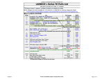


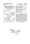

![Kenwood Z910DVD[R] User's Manual](http://vs1.manualzilla.com/store/data/007020200_1-b05420062acc26a5eda7b041010caf89-150x150.png)