1
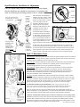
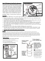
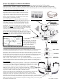
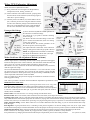
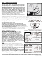
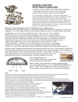
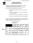
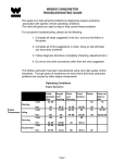
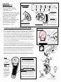
Opel CIH:
Ignition System
The Opel ignition timing
is designed to be set at TDC
(Top Dead Center).
Adjustments are made to the point
gap (.018” on most), and operation
is checked at idle with a dwell
Meter. Dwell is to be set to
50 degrees +or- 2 degrees.
This test is to be performed with
the distributor vacuum hoses
disconnected and plugged.
Firing Order is 1-3-4-2.
Opel 1.9 Engine
Firing Order:
Rear of
Engine
1-3-4-2
Vacuum Advance
Connected by larger
hose, to ported
vacuum outlet,
on carburetor base
Lower Front Crank Pulley
Can be rotated clockwise
with a 19mm wrench on
bolt, to align timing marks
Vacuum Retard
Connected by smaller
hose, to port on brake
booster tree fitting,
on intake manifold
Opel CIH Distributor (1970-73 type vacuum canister shown)
Internal Shaft & Rotor rotates clockwise when engine turns
(1) How to Verify #1 TDC Camshaft Sprocket Timing
Generally, if an engine ran (without backfiring) prior to a tune-up, it can be
presumed the timing marks are probably in alignment. If the engine doesn’t
run, or backfires on cranking, or is low on power, then there is a chance it
may be caused by cam timing being off. To inspect timing marks for #1
TDC alignment, the camshaft dowel pin needs to be in the lower-center
“6 o’clock” position (1A), at the same time that the small ball marker on the
flywheel is lined up with the pin in a window, on the lower passenger-side
rear of engine (1B). Note: this is not how to align the cam timing but it is
how to verify if you are aligned for #1 cylinder firing position. Cam timing
is always done on #4 TDC, see below.
To view the camshaft dowel pin, either remove the valve cover, or
remove the triangular plate (held with three 10mm bolts) on front of the
cylinder head. Use a flashlight, and consider the angle from which you are
viewing, to determine correct “6 o’clock” position of the camshaft sprocket.
Correct #1TDC
1A
1B
(1A) Camshaft Dowel Pin at “6 o’clock” bottom and - Flywheel ball mark (1B) lines up with pin
(1B)
To view the window where the flywheel ball becomes visible, look below
the manifold (near the oil pressure sender unit), until the ball rotates into
place (when the crank pulley on the front of the engine is turned with a
19mm wrench, preferably done with the spark plugs removed) (1C) (1D).
Because Opel didn’t put a timing mark on the lower crank pulley until 1975 (and
later European) models, the marks on the front of the timing cover won’t help you.
#4 TDC:
— Cam dowel pin
at “12 o’clock”
— Also ball mark
on edge aligns
through center of
sprocket (not just
vertically), with
slot in support plate
#4 TDC is correct
for Opel engine
assembly, but then
the crank pulley
needs to be rotated
360 degrees (one
full turn) to line up
cam sprocket for
correct timing
at #1 TDC.
Avoid This Common Mistake
when assembling an Opel engine:
A common error is when Opel
engines are assembled in the #4 TDC
position, but not rotated to #1 TDC
position before installing distributor.
This is because of mistakes in the service
manuals, and confusion caused because
the crank pulley groove and crank
keyway (& flywheel ball/pin) align at
“12 o’clock” when the engine is at both
#1 and #4 TDC. (Crank turns twice, to
every 1 camshaft rotation).
Sometimes, uninformed mechanics
install distributors 180 degrees off.
Therefore, the only mark location that
really counts, is the camshaft dowel pin.
(1A)
(1C)
(1D)
www.opelclub.com (6/2006)
Opel Distributor Installation & Adjustment
#1 TDC
Once the engine timing marks are confirmed to be properly aligned,
then the distributor rotor should be located where it is pointing at the
mark on its housing for the firing position for the #1 cylinder.
Distributor
Gasket, is
installed
dry (with
No sealer)
Loosen the 13mm bolt on the
distributor clamp,, to adjust or
remove distributor.
Removing an Opel
distributor requires
removing the
mechanical fuel
pump first. Always
reinstall with the
required fuel pump
spacer gasket.
Distributor
keyway end,
must slide
into gear cog
for distributor
to fully seat
in mount hole.
If the distributor is misaligned so
much that the rotor points to a firing
position for another cylinder, or so
that the vacuum canister is turned
Installation Position
close to the engine, then the
distributor should be removed
(which requires removing the
mechanical fuel pump first), then
reinstalled correctly (with its
thin gasket also set in place).
Rotor
#1 TDC
Mark
15-20 degrees
To install the Opel 1.9 distributor
so that the rotor lines up with the
#1 TDC mark, you need to reach
into the distributor mounting area
Align gear cog
keyway, to
with a long flat-blade screwdriver,
install distributor
to rotate the oil pump gear cog to a
position approximately 15 to 20
degrees clockwise of the #1TDC mark, or to the position the dist. shaft requires.
In most cases, this is a position that would be about 4:30 on a 12-hour clock
(when looking straight from the fender). When you set the distributor in place,
the rotor will move counter-clockwise that 15 to 20 degrees (because of action
of the angled drive gear teeth on the distributor shaft). After installing the distributor correctly, then apply sealer to pump spacer and re-install fuel pump.
Opel 1.9 Distributor Notes
1968-1969 type: Features separate vacuum canisters for ignition advance and retard, which sit
on engine side of housing. Also has unique round-hole condenser and a unique 1968-69 only
distributor cap (has indentation on lower inside ring of cap).
1968-1969
Advance
Vacuum
1968-1969
Retard
Vacuum
Lube Shaft Here
(Round or
square hole?
Need to look here,
to verify
which type.)
Retard // Advance
1970-72 and
1973-74 types
1970-1972 type: Features combined vacuum canister for both advance and retard functions.
Has a round hole in casing for condenser wire. Breaker plates & vacuum canister are
non-interchangeable with 1973-74 type condensers and housings.
1973-1974 type: Appears identical to 1970-1972 type distributor, but uses a square hole
in casing for condenser wire. (A round hole type condenser will fit in this distributor,
but breaker plates and vacuum canister are not interchangeable with 1970-72 housings).
This model can be modified (with experience and skill), to full mechanical advance,
using parts from Bosch (VW) #A009 distributor.
1975 type: Originally installed only on factory fuel-injected 1975 Opels. Features internal
mechanical advance, retard-only vacuum port, and unique ignition points (set to .016” gap).
Sometimes installed on Opels modified with dual side-draft carburetors (which do not have
ported vacuum fittings for the vacuum advance ), or vehicles with high-lift camshafts
(producing irregular vacuum). No performance gain if you use it on a stock engine.
ALL Distributor Models, require maintenance: Place drops of oil onto the felt
(in the center of the top of main shaft), to help keep mechanical advance adequately
lubricated. Lubricate the points rubbing block and cam lobes with ignition lube.
There are slight variations in advance profiles between various distributor models (see
number on housing to verify applications). Also periodically disassemble, clean & lubricate
surfaces between the internal breaker plates and on the main distributor shaft lobes.
ALWAYS clean distributor housing where condenser is mounted, to assure good ground!
Rear of Car
Vacuum Retard
only (used with
Fuel injection)
1975 type
Distributors are known to wear on the internal central brass bushing over time, which causes
the main shaft to wobble excessively and wear out ignition point rubbing surface quickly.
Replacement of ignition points with electronic ignition systems will prolong failure, but the
solution is to replace worn-out distributors with rebuilt models.
www.opelclub.com (6/2006)
Opel CIH Ignition Point/Dwell Adjustment
Opel GT Ignition Point Set
Point-Set
Opel owners know, that the Opel distributor can “eat”
Hold-down
screw
ignition points quickly. This is because the high RPM’s
of a 4-cylinder Opel engine, combined with improper
“Top” of
maintenance, wears the internal distributor bushings
shaft lobe
within about 70,000 miles, and the center distributor
shaft “wobbles” on the rubbing block of the point set.
Inspecting
One symptom of worn-out points, is idle speed drops.
Contact
Surfaces:
Higher voltage, caused by failing ignition coils and
circuit “resistance” wires to that coil, also results in
premature “pitting” on contact surfaces of point sets.
Procedure :
(1) Unscrew the “hold-down” screw, remove clip to condenser, and remove point-set from distributor.
(2) Inspect the contact surfaces, to check for a flat surface or pitting. (In most tune-ups, standard procedure
is to just replace the point-set and condenser altogether).
(3) Assemble new point set in place, apply high-revolution ignition grease on the rubbing surfaces of the distributor shaft (occasionally, this comes in a capsule with the ignition point set).
(4) Rotate engine (with a 19mm wrench on the crankshaft pulley bolt, or by engaging 2nd gear and pushing
the car backwards), until the rubbing block of the point set rests easily upon the “top” of a shaft lobe.
(5) Use a “feeler gauge” of .018” (thousands of an inch) to set a gap between the contact surfaces, then snug
the hold-down screw.
(6) To check the accuracy of the setting: Install the distributor rotor, cap and wires.
(7) Then place the car in “neutral” gear or “park” gear (with brake on), then connect “Dwell Meter” to the
negative terminal of the ignition coil and a ground (a valve cover bolt is a good location for a ground).
(8) Start the vehicle, and read the setting on the Dwell Meter.
Results:
The needle or gauge should read at a steady 50 degrees, and shouldn’t vary more than 2 degrees (ie lower than 48 or
more than 52), even when accelerating the engine. If the needle varies more than 4 degrees, the distributor may be worn out.
(Note: Some older Dwell Meters use an 8-cylinder gauge: If so, correct measurement is 25 degrees, plus or minus one degree).
If reading is more than 52 degrees, the points are not open enough. Stop engine, and re-adjust the point set gap a bit more open.
If the readout is below 48 degrees that means the points are too far open. Stop engine and readjust point gap a bit more closed.
Repeat above procedure, until dwell readout is steady and within the proper measurement range.
Ignition Coil Notes:
The wire to the tachometer, connects to the coil’s negative terminal
If the tach gauge needle “jumps” a lot, this wire connector is loose.
Original style ignition coils have 1.5 ohms resistance
(measures 2.3 amps at the positive terminal with engine running,
and 13.5 to 14.5 volts alternator output).
A non-original “resistance type” coil (used when the
“clear” resistance wire” is replaced, measures 3 ohms).
Note:
The “Clear” coated resistance wire
limits current to the ignition coil.
This helps to prevent “pitting” on
contact surface of ignition points.
This “clear” resistance wire should
be replaced with a 1.8 ohm aftermarket ballast resistor if the points
are pitting quickly, or when the
point set is replaced with an
aftermarket electronic ignition kit.
www.opelclub.com (6/2006)
Weber 32/36 DGEV Carburetor Installation
The Weber 32/36 DGEV carburetor is the most popular carburetor operated on the Opel 1.9 liter engine.
Unlike most Solex 32DIDTA carburetors, the Weber offers a steady idle speed, reliable performance, and generally
better fuel economy. Proper operation of the Weber 32/36 carburetor depends on correct installation and correct tuning.
Air Filter Option: 2 1/2” tall Weber air filter kit.
Most Weber carb installations also use the Weber air filter kit. The
other option, is using the Opel GT original air filter “cap”, with an
adaptor that mounts to the top of the Weber. To clear the underside
of the GT hood, it may be necessary to trim the lower edge of the
“cap” about 1/2”. Other alternatives include the “K&N” brand air
filter kit, and the newer Weber “air induction cap” (which works
with the original GT round air filter cannister).
Weber 32/36 DGEV Carb: -Electric-choke version shown-
Weber Aftermarket Air Filter
Original Opel GT Air Filter “Cap”
Electric Chokes are the best upgrade, but Water chokes can also be used.
Note: Water chokes work best in relatively cold weather (below 45F).
Current Weber versions are “series 33B” (inscribed on the lower edge,
facing the engine), and older 1970’s versions are the DGV “series 5A”.
Used Webers: Always check the throttle shaft on a used Weber for up and
down play at the “ball nut”. An excessively worn throttle shaft bushing
indicates a high mileage carburetor and often coincides with a vacuum leak
at the shaft, which causes problems with tuning and idling.
Electric Choke
‘Key-On’ 12V source
on the fuse box. NOT
to the ignition coil.
Weber Throttle Linkage installation sequence. - Illustrated Below On a new Weber, remove the Weber throttle shaft nut & replace it with the
Solex Ball Nut. Also inspect the throttle linkage between the gas pedal and
carburetor including the firewall mounted grommets, lubrication of linkage
“ball” connectors.
Note: Fully depress gas pedal and
check for full carburetor operation.
If not. Adjust the throttle shaft on
the drivers side until carburetor
opens fully under full throttle.
Weber Model and
Series Markings
Seen on lower edge,
facing the engine.
Carburetor “Thick” Base Gasket, and (optional) Heat Shield with “Thin” Gasket:
Install a “Thick” base gasket to properly seal the carburetor to the manifold or heat shield
(if equipped). Use a high quality gasket sealer, such as “Permatex High Tack”, on all surfaces between
the top of the manifold and the bottom of the carburetor, to prevent common Opel vacuum leaks.
“Thick” Gasket
Other gaskets, such as the Weber “fiber” gasket, are too thin to seal properly or repel heat, and the
Opel plastic gasket restricts the 36mm barrel of the Weber. Installation without gasket sealer or with
improper gaskets, will allow vacuum leaks to form over time. These leaks will make tuning the Weber
carb more difficult, due to the resulting excessively “lean” condition. Note: Lean conditions raise
internal cylinder head temperatures (which can crack the exhaust manifold).
Heat Shield
Note: In warm climates, installation of the Opel “Aluminum Heat Shield” will help shield the
carburetor from the exhaust manifold heat. This heat can cause a “vapor lock” condition, making the
vehicle more difficult to restart. Note: The heat shield requires an additional “Thin” mount gasket.
“Thin” Heat
Shield Gasket
Intake Manifold:
The Intake Manifold uses studs with two thread pitches. 1.25mm pitch into the manifold, and
1.0 pitch for the carburetor mounting nut. The smooth portion of the stud helps to prevent
vacuum leaks. Factory Bulletins suggest the installed height of the studs, to be 1 1/2” above
the manifold surface. Original Carburetor Mounting Nuts sized 13mm.
Note: Many owners mount extra washers on the intake manifold studs, to reduce the number
of wrench turns required to tighten the carb mount nuts. Using a “stubby” (less than 3 1/2”
long) open-end 13mm wrench also helps greatly in this tight access area.
Check the for vacuum leaks where the manifold seals to the cylinder head, as well as for loose
manifold 15mm mounting bolts. Repair as needed. Make sure that the 4 central 15mm
mounting bolts use the 5/32” thick washers, with the thinner 1/16” washers on 2 end bolts.
Additional intake manifold hardware includes the “brake booster tree” fitting, connecting to the brake
booster vacuum hose. This fittings threads should be wrapped with Teflon tape, to prevent vacuum leaks.
Note: Check for leaking or cracked vacuum hoses and replace accordingly, before you can correctly adjust
the idle mixture and the idle speed.
www.opelclub.com (6/2006)
Electric Choke
(Loosen ring to adjust)
Weber 32/36 Carburetor Adjustment
Weber Carburetor Adjustment Procedure.
(3a) Idle Jet
& Screw Mount
(1) First, perform the various engine tests & adjustments;
Compression, Points, Timing, Vacuum, etc.
(2) Clean Carburetor with carburetor-cleaner, spraying down
the main throats of the carburetor (with running engine at
a fast idle, to prevent stalling).
(3) Carefully remove the Idle Jet (3a) and the Mixture Screw
(3b). Clean the jet and screw using the carburetor cleaner
as well as the carburetor passages. Reinstall the Idle Jet, &
fully screw in the Idle Mixture Screw, lightly bottoming
out the screw and back it off 2 full ‘360 degree’ turns.
Passenger Side Linkage
(4c) Throttle
Grommet at
firewall
Return
Spring
(4b) Spring
clip, attaches
rod end to
carb linkage
Attaches to Carburetor
Idle Speed Screw
(3b) Idle Mixture
Screw
Linkage Adaptor
Bracket & Ball Stud Nut
(4) Next check the adjustment and full operation of
the carburetor acceleration linkage.
(4a) Check the 3 gas pedal to firewall mounting
screws are tight,
(4b) Ensure the ball and socket fittings on the linkage are cleaned and lubricated. (check for missing
“spring clip” retainers)
(4c) Check that the two throttle grommets on the
firewall are present, clean and greased.
(4d) Adjust Throttle Control Rod, so that carburetor
linkage is fully opened when the gas pedal is floored
NOTE: If equipped with an automatic transmission,
also adjust the “Kickdown” detent cable. (See Opel
factory service manual for instructions).
Hose Port for
Vacuum Advance
Driver’s Side Linkage
14mm Fuel
Inlet fitting
(reversible
on newer
models)
(Linkage toward
Carburetor)
(Drawings are Not to Scale)
(4d) Adjust
Throttle
Control Rod here
(4c) Clean
Automatic
Transmission
Detent Cable
Mount Hole
(if equipped)
(4a)
Gas
Pedal
Screws
and lube rod
end, and
insert throttle
grommet
(in the firewall
area hole
closest to the
fender).
Weber Carb Lean Idle Adjustment Method: (at home)
Run the engine until it is warmed up and the choke is fully opened and disengaged.
Rotate the Idle Speed screw counter-clockwise, until tachometer reads about 600-700
rpm’s (as low as it can idle, with the engine still running). Next rotate the
Idle Mixture crew (3b), also known as the fuel mixture adjustment screw) clockwise,
until the engine runs rough.
Next turn the Idle Mixture screw (counter-clockwise) 1/2 to 3/4 of a full turn, so that
the engine again runs smoother. Next increase the idle speed by rotating the Idle
Speed screw clockwise. Most Opels Factory idle speed setting is 850RPM, but most
owners adjust their idle between 1000-1100 RPM
Note: Too High of an idle speed will engage the distributors mechanical advance
affecting ignition timing.
a.k.a. Idle Mixture Screw (3b)
Usually this is a 8mm screw.
View is from the windshield
area, where carb linkage is.
Note: Above procedure is for home. Exact Fuel Mixture adjustment is performed at a shop.
Additional Weber Carb Notes:
Idle Mixture Screw Circuit Function
Setting Choke: The choke is adjusted, by loosening the three screws on its “ring,” then
rotating the choke clockwise for less choke, and counter-clockwise for more choke.
Note: The Fast Idle Speed screw is located behind the choke itself, and can be adjusted
to increase or decrease the fast idle rpm. A good fast idle speed (when the choke is
Too far in
Just Right
closed) is about 1700 RPM
Water Choke: The hoses attach to 2 “T” fittings coming from the heater hoses.
Electric Chokes: Wire to the #2 fuse (same switched circuit as the radio) on the Opel GT fuse box.
Avoiding Vapor Lock: This is a particular problem with all Opel’s in Summer time. Route fuel hose away from all hot engine surfaces.
Only install fuel filters after the fuel pump near the carburetor, staying clear of the thermostat housing. Installing a clear plastic fuel filter
near the carb, will let you see when fuel is vaporizing. Carrying and using starter spray is a quick-fix. A Carburetor heat shield also helps.
Weber Fuel Inlet Fitting: Newer Weber carbs have a reversible 14mm brass fuel inlet fitting, so you can relocate the fuel hose away
from the engine.
Fuel Regulator: A good prevention move, is installing a “fuel pressure regulator” on the hose leading to the carb, set at 3.5psi. Some
new mechanical fuel pumps, and some aftermarket electric fuel pumps can develop excessive pressure (which can flood some Webers).
Additional Information: Weber technical guides discuss operational circuit function and provide float adjustment specifications.
Weber carburetors are also highly tunable. If you upgrade cams, exhaust, ignition, the Weber is easily tuned for
more performance by changing the main fuel and idle fuel jets. Replacement parts are also readily available.
www.opelclub.com (6/2006)
Opel 1.9 Vacuum System Operation
Air/Fuel Mixture
from Carburetor
The “Opel Vacuum Solution” flyer, originally printed in the January
1996 OMC Blitz newsletter, is one of the most widely distributed OMC
Tech Tips. This page will help to update the 1.9L engine tune-up.
The Opel 1.9L engine draws the carburetors fuel/air mixture through the
intake manifold “round the bend” into the cylinder head, past the valves
into the combustion chamber. Ported Vacuum advances the ignition
timing via the distributor vacuum advance, and the Manifold Vacuum
retards the timing via the Vacuum Advance at idle. Manifold vacuum
also operates the Brake Booster, ventilates the Crank Case, and on
automatic transmissions operates the Vacuum Modulator.
Therefore, it’s important to test and identify any vacuum leak sources.
Mixture goes “Round the bend”
Diagnosis isn’t difficult. Typical symptoms include: Hesitation, Stumble or Surge pattern of acceleration, and an inability to
idle smoothly below about 1100 RPM. (The engine may idle smoothly at higher than normal idle speeds, such as 1300 to
1800 RPM) A loss of engine “torque” may also be noted. If you can turn the Idle Mixture Screw ‘IN’ all the way (without
the engine stalling), you most likely have the idle speed rpm screw set too high, possibly indicating that you have a vacuum
leak somewhere.
Testing for a Vacuum Leak at the Intake Manifold
Use a can of common Carburetor Cleaner.
Insert and aim the long red straw nozzle, at the gasket between the
cylinder head and intake manifold, and spray a short stream of carb cleaner.
If the engine begins idling faster, smoother, stops misfiring, or decreases rpm,
you have found the location of a vacuum leak.
This same procedure can be used to test the carburetor base gasket & carb throttle
shaft area, to check the brake booster fitting, hose, check valve and fitting,
as well as the master cylinder to brake booster seal and the booster itself.
Testing for a Leak in the Vacuum Hoses
Once you know there is no vacuum leak at the intake
manifold gaskets, or at the brake booster fitting, then test the
vacuum hoses, while the engine is idling. Pull each hose,
one-by-one, and place your finger over its exposed port. If the
engine speed goes faster, that hose or fitting is leaking somewhere.
Brake Booster and Hose: Disconnect the if booster hose from the
manifold and plug to test. If the engine idles better, that hose may be
leaking. You also want to check/test the booster check valve, inlet
fitting and seal, as well as the master cylinder to booster “O” ring.
Note: Another symptom of a leaking booster, is when an idling
engine dies as you depress the brake pedal.
Integral PCV Fitting located on 1973 & 74 manifolds.
Vacuum Fitting
Typical 68-72
The Brake Booster Hose
fitting on manifold, should
have its threads sealed
with Teflon tape.
Check hose from carb. to distributor advance.
Notes:
“A” Booster Hose to Booster. Use a proper reinforced air hose.
Do NOT use ordinary heater hose — it will collapse under vacuum.
Note: The Booster “Check Valve” is originally located within 10
inches of the intake manifold fitting.
“B” Integral PCV Fitting for engine, via the small valve cover hole.
(You may use regular vacuum hose for this fiting.)
Note: The Integral PCV fitting was relocated to back side of manifold
on the 1973-74 engines, for a port to operate the 1973-74 EGR valve.
“C” Manifold Vacuum to Distributor Retard Port on distributor.
“D” Manifold Vacuum for the Automatic Transmission Modulator
(when vehicle is equipped with an automatic transmission only!)
After locating and repairing any and all vacuum leaks, readjust carburetor idle mixture and idle speed as necessary.
www.opelclub.com (6/2006)
OPEL MOTORSPORTS CLUB
OMC is an independent US-based auto club, that
specializes in German- made 1968-1975 Opels.
OMC was founded in 1980 by Opel enthusiasts
who wanted to share information and promote their
marque in motorsports. A newsletter was established
to promote Opel events, report Opel-related news,
provide technical tips, discuss vehicle upgrades,
and give members a free place to advertise.
New “Full Memberships” receive:
A year of bi- monthly print issues of OMC newsletter “The Blitz,” a roster of club members, an OMC decal
and a window emblem. Members can also participate in local OMC chapter activities, held all over the USA.
OMC Newsletters: “THE BLITZ”
(Print version black/white; Online in color)
OMC Activities & Annual Meeting
Opel Motorsport Club is the longest-established Opel club in the U.S.A. Members travel great distances
to attend the OMC Annual Meeting, a mid-Summer gathering and display of classic and restored Opels.
Benefits of membership also include information from other Opel owners on the maintenance and
improvement of their Opel(s), and the ability to contact fellow members on their common interests.
Opel Motorsport Club funds help maintain our website (with helpful Opel information) at: www.opelclub.com
OMC’s peer-reviewed technical information helps owners avoid common and costly errors on Opel repair jobs!
OMC is officially recognized by the Opel factory of Russelsheim, Germany, and OMC “SOLO II” racing
activities are also sanctioned by the SCCA (Sports Car Club of America) for racing nationwide in the USA.
“Full” U.S. Membership: $45.00 (Includes bi-monthly b/w print issues of The Blitz, postage & benefits listed above)
“Online-Only” Member: $20.00 (Includes downloadable Acrobat .pdf version of The Blitz, for home color printing)
To Join: Send your name & address, with check/money order payable to “Opel Motorsports Club” by mail to:
OMC Treasurer, 3824 Franklin Street, La Crescenta CA 91214-1607
OR: Send $47 for Full US Membership or $22 for Online Membership,
via PayPal to: [email protected]
(International Members: Please Add $10. for Full Membership, to cover additional postage costs )