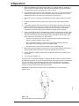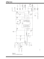
1
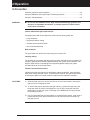
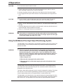
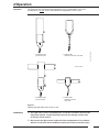
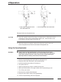
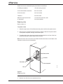
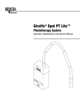
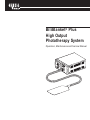
BiliBlanket® Plus
High Output
Phototherapy System
Operation, Maintenance and Service Manual
Pow
er
Air
FailuFlow
re
Tra
nsillu
mina
tor
Pow
er L
evel
Photo
the
rap
y
BiliB
lan
Med
Pho
PLUS
toth
Pho
era
Hig
Low
h
Me
diu 15
Hig m + 3.7
25 + 5 uW
h
35 + 6.25 /cm2
8.7 uW/cm /nm
5 uW 2
/cm2/nm
/nm
toth
ket®
erap
WW
ar
Conn ning:
ect Inten
Pad se
Prior Light
to Op
era
yS
tion
yste
m
User Responsibility
This Product will perform in conformity with the description thereof contained in this
operating manual and accompanying labels and/or inserts, when assembled, operated,
maintained and repaired in accordance with the instructions provided. This Product
must be checked periodically. A defective Product should not be used. Parts that are
broken, missing, plainly worn, distorted or contaminated should be replaced immediately. Should such repair or replacement become necessary, Ohmeda recommends
that a telephone or written request for service advice be made to the nearest Ohmeda
Regional Service Center. This Product or any of its parts should not be repaired other
than in accordance with written instructions provided by Ohmeda and by Ohmeda
trained personnel. The Product must not be altered without Ohmeda’s prior written
approval. The user of this Product shall have the sole responsibility for any malfunction
which results from improper use, faulty maintenance, improper repair, damage or
alteration by anyone other than Ohmeda.
CAUTION
w Federal law in the USA and Canada restricts this device to sale by or on the
order of a licensed medical practitioner.
i
6600 0341 000
04/25/00
i
Table of Contents
1/General Information ..................................................................................................... 1
Description ...................................................................................................................... 1
Light source controls, indicators and connectors ............................................................ 4
Accessories and replacement parts ................................................................................ 6
2/Operation ...................................................................................................................... 1
Checkout procedure before operation ............................................................................ 2
Checkout procedure ............................................................................................... 2
Using the BiliBlanket Plus High Output Phototherapy System ....................................... 3
Using the transilluminator ............................................................................................... 6
3/Maintenance ................................................................................................................. 1
Maintenance schedule .................................................................................................... 1
Operator maintenance .......................................................................................... 1
Service maintenance .............................................................................................. 1
Cleaning and disinfecting ................................................................................................ 1
Bulb replacement ............................................................................................................ 2
Cleaning the fan filter ...................................................................................................... 4
Attaching the dovetail rail mounting bracket accessory .................................................. 4
4/Service .......................................................................................................................... 1
Repair policy and procedure ........................................................................................... 1
Troubleshooting .............................................................................................................. 2
Functional description ..................................................................................................... 3
Repair procedures .......................................................................................................... 4
Replacing a fuse .................................................................................................... 5
Replacing the light source cover ............................................................................ 6
Replacing the PC board ......................................................................................... 6
Replacing the cooling fan ....................................................................................... 6
Replacing the brightness control ............................................................................ 7
Replacing the power supply ................................................................................... 7
Replacing the thermal cutout switch ...................................................................... 8
Replacing the optical filter assembly ...................................................................... 8
Replacing the bulb holder ...................................................................................... 9
Replacing the power inlet module .......................................................................... 9
Replacing a bezel/hour meter .............................................................................. 10
Replacing a front bezel label ................................................................................ 10
Electrical safety procedures .......................................................................................... 11
Ground continuity ................................................................................................. 11
Leakage current ................................................................................................... 11
Light Output Measurement ........................................................................................... 11
Illustrated service parts ................................................................................................. 13
Schematics ................................................................................................................... 17
Appendix .......................................................................................................................... 1
Specifications .................................................................................................................. 1
i
6600 0341 000
04/25/00
i
General Precautions
IMPORTANT CLINICAL INFORMATION
PLEASE READ CAREFULLY BEFORE USING THIS DEVICE
Care of the Skin
The skin serves as a protective barrier against chemical, mechanical, and biological
insults. The skin is also important in the regulation of body temperature and serves as
a route of water excretion, especially in premature infants. The introduction of new
intensive-care techniques has been associated with the increased survival of very
small, premature infants. The immaturity of the skin of the very low weight infants,
coupled with excessive instrumentation and handling, poses previously unrecognized
problems for the nursing care of these infants1.
Please read, evaluate and implement the following recommendations as appropriate:
1. Please refer to the following standard of skin care recommendations as given in the
literature2 when utilizing this device with all infants. Special attention should be
given to sanitation and skin integrity.
• Observe color, rashes, excoriation
• Clean skin with warm water
• Clean perineal area after stooling
• Change infant’s position every 2 hours
2. This device is intended only for the treatment of existing hyperbilirubinemia. Use of
this device for prophylactic treatment, particularly of premature infants, is not
recommended. These infants have extremely fragile skin3 and various clinical
studies have produced inconsistent conclusions concerning the effectiveness of
prophylactic phototherapy treatment 4 5.
ii
1
NAACOG(1992), OGN Nursing Practice Resource, Neonatal Skin Care, NAACOG.
2
ibid
3
Rutter, N., The immature skin, British Medical Bulletin, Vol. 44, No. 4, 1988
4
Curtis-Cohen, M., et al, Randomized trial of prophylactic phototherapy in the infant with very low birth weight, TheJournal
of Pediatrics, July, 1985
5
Brown, A., et al, Efficacy of Phototherapy in Prevention and Management of Neonatal Hyberbilirubinemia, Pediatrics,
February , 1988
6600 0341 000
04/25/00
ii
General Precautions
Definitions
What the attention
symbol means
Next to each warning or caution, we have placed an “attention, read
accompanying documents” symbol to alert you to the presence
of these important statements. This is the attention symbol:
w
When the attention symbol appears in front of text that is printed on the system itself,
it means that the text is elaborated upon in the operation manual.
WARNING: A Warning statement is used when the possibility of injury to the patient or
the operator exists.
CAUTION: A Caution statement is used when the possibility of damage to the equipment exists.
~
Indicates alternating current.
m
Indicates IEC Type B equipment.
T
This letter appearing before a fuselink value indicates a time delay fuselink.
Important: An Important statement is similar to a note but is used for greater emphasis.
Note: A Note provided additional information to clarify a point in the text.
The following are general Warnings and Cautions. Precautions specific to
certain procedures are found in the text of the manual.
WARNINGS
w
Do not use the BiliBlanket Plus Phototherapy System in the presence of flammable
anesthetics; a possible explosion hazard exists under these conditions.
Service described in this manual must be performed by a technically competent
individual as described in this manual. Detailed drawings and procedures for more
extensive repairs are included in this manual solely for the convenience of qualified
personnel having proper knowledge, tools and test equipment, or for Ohmeda service
representatives.
CAUTIONS
w
Servicing of this product in accordance with this service manual should never be
undertaken without the proper tools, test equipment and the most recent revision of this
service manual which is clearly and thoroughly understood.
iii
6600 0341 000
04/25/00
iii
Notes
iv
6600 0341 000
04/25/00
iv
1/General Information
In this Section
Description ...................................................................................................................1-1
Light source controls, indicators and connectors ......................................................... 1-4
Light source and pad ........................................................................................... 1-4
Light source back panel ...................................................................................... 1-5
Accessories and replacement parts ............................................................................. 1-5
WARNING
w Do not turn on or operate the BiliBlanket Plus High Output Phototherapy
System in the presence of a flammable anesthetics; a possible explosion
hazard exists under these conditions.
General Information
This manual describes how to checkout, operate and maintain the Ohmeda BiliBlanket
Plus High Output Phototherapy System. It also describes for the technically competent
person how to service the BiliBlanket Plus High Output.
Before using the BiliBlanket Plus High Output Phototherapy System
• Read through sections one through three of this manual.
• Pay special attention to the Warnings and Cautions which appear in the manual.
• Read the User Responsibility statement located on the inside front cover; it describes what is expected of the user to maintain a safe and accurate product.
• Read the Warranty; it describes Ohmeda’s responsibility in case of a functional
defect.
Keep this manual available for answering questions which may arise.
Description
The new BiliBlanket Plus High Output pad, which can be identified by the gray cable,
provides higher intensity levels than the original BiliBlanket Plus High Output pad with the
white cable. Both pads can be used with the BiliBlanket Plus High Output or BiliBlanket
Plus High Output light source box, however, the pad with the white cable will provide lower
intensity levels.
The Ohmeda BiliBlanket Plus High Output Phototherapy System uses a fiber optic cable
to deliver light from a high intensity lamp to a woven fiber optic pad. The pad is placed in a
disposable cover that is in contact with the patient. The patient is exposed to light in the
ideal 400 to 550 nanometer range for phototherapy treatment.
On units with the transilluminator option, unfiltered light in the visible spectrum travels
through a flexible light pipe to appear at the tip of the transilluminator cable. The light from
the cable is used to facilitate vascular sticks or injections. It is also used to find pneumothoraces.
The BiliBlanket Plus High Output Phototherapy system consists of a light source unit and
a light pad with a four foot long fiber optic cable. The light source unit contains a lamp, light
filters, a variable power supply for the light source, a cooling system and overheating
protection near the lamp.
The light source lamp is a high intensity, tungsten halogen bulb with a built-in reflector.
The reflector is coated with a dichroic surface which reduces the infrared energy
transmitted. This bulb is specifically manufactured for use with the BiliBlanket Plus High
Output.
1-1
6600 0341 000
04/25/00
1-1
1/General Information
A light filter, positioned in front of the lamp, rejects light outside the 400 to 550 nanometer range. This filter blocks nearly all ultra-violet and infrared light; only the blue light is
allowed to pass. This filtered light is focused on the inlet of the fiber optic cable.
Light intensity may be selected by the front panel brightness rotary control. Control
range is from 19± 4.75 µW/cm2/nm at full counter clockwise to 45± 11.25 µW/cm2/nm
at full clockwise with a medium detent at 32± 8 µW/cm2/nm. See Light Output Measurement Procedures in Section 4 for precise light output measurement.
Mode select
Selects the operating mode ; phototherapy or transillumination. Using the Ohmeda
transilluminator light pipe, the BiliBlanket Plus High Output System can be used as a
transilluminator.
Supply power
Power for the light source unit can be supplied by any standard AC mains power
source at either 50 or 60 Hz that have voltages in the range: 90 - 132 or 180 - 264.
Power enters the light source through a receptacle that has an integral power switch.
Cooling
A fan cools the light source unit. A thermal cutout switch located next to the light-filter
protects the light source unit and fiber optic cable or transilluminator from overheating.
Fiber optic cable
The fiber optic cable contains 2400 individual plastic fibers which transmit the light from
the light source to the light pad. The light pad is constructed by weaving these fibers
into a mat. This patented process produces a pad with light over the entire surface.
These fibers are randomized in the cable to eliminate any local intensity gradients due
to bulb hot spots, dust on the filter, dust on the cable end, etc. This allows the nearly
uniform, continuous blanket of light. A disposable protective pad cover is provided to
reduce the risk of cross-contamination and make the patient more comfortable.
Disposable cover
The disposable cover is designed for use with both premature and full-term infants. The
infant lies directly on the disposable-covered pad without any method of attachment
between the pad and the infant.
1-2
6600 0341 000
04/25/00
1-2
1/General Information
Disposable vest
A disposable vest is designed to secure the fiber optic pad to the infant. With the
disposable vest, it is possible to hold and nurse the infant while continuing phototherapy treatment. The disposable cover should be used for premature infants and fullterm infants who can’t tolerate having the vest secured around the midsection.
Transilluminator
The transilluminator light pipe contains plastic fibers which transmit light from the light
source to the tip.
1-3
6600 0341 000
04/25/00
1-3
1/General Information
Light source controls, indicators and connectors
8
7
2
1
3
4
5
6
Transilluminator Unit
2
3
4
6
CI.29.001,.002
1
Nontransilluminator Unit
Figure 1-1
Light source, pad and transilluminator cable
1-4
6600 0341 000
04/25/00
1-4
1/General Information
Refer to Figure 1-1.
Power indicator
1. The green light-emitting diode (LED) lights when the light source unit power is on.
Air flow failure indicator
2. The red light-emitting diode (LED) lights when there is an air flow failure.
Timer
3. Nonresettable timer runs whenever the bulb is turned on.
Brightness selector
4. The rotary control selects the light intensity, and has a center detent at the medium
intensity position. (see Table 1-1 for light intensity values).
Mode select
5. The mode select slide selects the operating mode: phototherapy or transilluminator.
Light source port
6. The light source port is for attaching the fiber optic cable connector or transilluminator.
Pad assembly
7. The pad assembly attaches to the light source port. Light is fed through the optical
fiber cable to the optical fiber woven pad.
Transilluminator cable
8. The cable attaches to the light source port. Light appears at the tip.
CI..29.003
BiliBlanket Plus High Output
Phototherapy System
1
2
Figure 1-2
Light source back
Refer to Figure 1-2.
Power cord receptacle
1.
The power cord plugs into the power cord receptacle.
Power switch
2.
1-5
The power switch switches the light source unit on.
6600 0341 000
04/25/00
1-5
1/General Information
Accessories and replacement parts
Table 1-2
Stock number
Item
6600-0213-800
6600-0270-200
6600-0461-200
6700-0025-800
6700-0014-800
6600-1974-101
6600-0656-801
6600-0656-802
6600-0656-803
6600-0656-804
6600-0656-805
6600-0656-806
6600-0656-807
6600-0656-808
6600-0656-809
6600-0656-810
6600-0656-811
6600-0730-207
6050-0002-259
6030-0000-006
6600-0522-800
6600-0031-900
6600-0198-800
6600-0680-200
6600-0531-800
Carrying case
Disposable covers (50)
Disposable vest (50)
Mobile stand, less accessories
Mobile stand slide bracket assembly, female
User card
Pad assembly, English
Pad assembly, French
Pad assembly, Spanish
Pad assembly, German
Pad assembly, Italian
Pad assembly, Swedish
Pad assembly, Japanese
Pad assembly, Russian
Pad assembly, Greek
Pad assembly, Dutch
Pad assembly, Portuguese
Power Cord, North America (120V)
Power Cord, United Kingdom
Power Cord, Continental Europe
Transilluminator
Dovetail rail mount slide bracket kit, female (See A, Figure 1-3)
Dovetail rail mount slide bracket accessory, male* (See B, Figure 1-3)
Replacement lamps (6)
Transilluminator or accessories pouch
* Allows the BiliBlanket Plus High Output to be attached to the dovetail rail mount slide bracket by using two of the
mounting screws on the left side of the light source unit.
B
6600-0198-800
CI.01.032,033
A
6600-0031-900
Figure 1-3
Slide mounting bracket accessory slides into a dovetail mount slide bracket
Dovetail rail systems are used to mount accessories on Ohio® Care Plus® incubators
and Infant Warmer Systems.
1-6
6600 0341 000
04/25/00
1-6
2/Operation
In this section
Checkout procedure before operation ......................................................................... 2-2
Using the BiliBlanket Plus High Output Phototherapy System .................................... 2-3
Using the Transilluminator ........................................................................................... 2-6
WARNING
w Do not use the BiliBlanket Plus High Output Phototherapy System in the
presence of flammable anesthetics; a possible explosion hazard exists
under these conditions.
Factors which affect light output and life
Lamp light output and life are affected by various factors among which are:
• Lamp variations
• Brightness selector setting
• Vibration and mechanical shock
• Non-recommended lamp
Bulb variations
The light output from bulb to bulb may vary by as much as 10%.
Intensity setting
The bulb life will vary greatly with the intensity at which the light source is operated. For
example, operating at the lowest brightness setting may yield a nominal bulb life of as
high as 10,000 hours, but operating at the highest brightness setting may yield a
nominal bulb life of as low as 800 hours.
Vibration and mechanical shock
Vibration and mechanical shock will significantly reduce the bulb life. Care should be
taken when moving the light source. To maximize the bulb life, the light source should
be mounted or placed on a surface which is stable and not exposed to vibration.
CAUTIONS
w Allow the light source to cool for a minimum of ten minutes before moving the
light source or changing the bulb.
w To ensure the proper operation and light intensity, replace the lamp only with
the proper lamp as listed in the Appendix. Use of other lamps will affect the
performance of and may result in damage to the BiliBlanket Plus High Output
Phototherapy System.
w Use only Ohmeda light pad assemblies or transilluminator cables. Light pads or
transilluminators from other manufacturers can affect performance and may
damage the unit.
2-1
6600 0341 000
04/25/00
2-1
2/Operation
Non-recommended lamps
Using any lamp other than that recommended and distributed by Ohmeda for the
BiliBlanket Plus High Output system will affect the performance of and may result in
damage to the light source or the fiber optic pad or transilluminator.
Checkout procedure before operation
Before operating the Ohmeda BiliBlanket Plus High Output Phototherapy System, the
following steps should be taken to ensure that the BiliBlanket Plus High Output will
provide effective phototherapy treatment or the transilluminator delivers the proper
light. This checkout procedure assumes that you are familiar with the unit’s controls.
CAUTIONS
w Lamp life is greatly reduced if the lamp or the light source is subjected to shock
or bumping, or if the unit is moved while the bulb is hot. Allow the bulb to cool
for at least ten minutes before moving the unit.
w Do not allow the fiber optic cable, pad or transilluminator to rub on sharp or
abrasive surfaces. The protective coverings may be damaged.
w Observe the following fiber optic cable and pad assembly and transilluminator
guidelines:
• If you hang the fiber optic cable and pad or transilluminator assembly for temporary storage on an IV pole, door, wall hook or similar item, do not pull the cable
when removing it for use. Carefully lift the cable free of obstructions when ready
to use it.
• Do not lay the fiber optic cable or transilluminator where it could be crushed.
• Do not place anything on the fiber optic cable or transilluminator.
Not observing the guidelines may cause excessive stress and may:
• damage the cable’s outer protective conduit,
• damage the cable’s optical fibers,
• decrease light intensity at the light pad or transilluminator.
Checkout procedure
1. Place the light source on a flat, level surface (or use the mounting slide bracket) to
locate the light source within a few feet of the treatment location.
2. Verify that the air circulation vents on the sides of the light source are unobstructed.
The air filter should be free from excessive amounts of lint.
2-2
6600 0341 000
04/25/00
2-2
2/Operation
CAUTION
w Do not block the air intake or outlet.
3. Examine the power cord, fiber optic cable and transilluminator cable for obvious
signs of damage. Replace them if they are damaged.
4. Connect the power cord to the light source first and then to the line power supply.
5. Fully engage the fiber optic cable connector or transilluminator into the light source
port.
CAUTION
w Do not scratch or soil the light-input end of the connector cable. Do not put
sharp or heavy objects on the fiber optic pad, vest or connecting cable.
6. Select “|” on the power switch to turn the power on. The green power indicator light
will light.
7. Using the brightness selector switch on the front panel, select any light intensity and
ensure that light is being emitted from the pad.
8. Select “O” on the power switch to turn the power off.
WARNING
w A hot surface is exposed when the fiber optic cable is disconnected from
the light source port. Do not insert fingers or foreign objects into the light
source port whether the lamp is on or off.
Using the BiliBlanket Plus High Output Phototherapy System
The disposable cover is designed for use with both premature and full-term infants. The
infant lies directly on the covered pad without any method of attachment between the
pad and the infant.
WARNING
w If there is a concern about exposure to direct light from the light pad,
cover the patient’s eyes when using the BiliBlanket High Output Plus
Phototherapy System to shield them or when the BiliBlanket Plus High
Output is used in conjunction with conventional phototherapy lights. Eye
patch use with the BiliBlanket Plus High Output may not be necessary
under these conditions:
1. When using the vest.
2. When the pad is kept against the patient’s back.
3. When the patient is clothed after applying the pad to the patient’s chest
or abdomen.
The disposable vest secures the fiber-optic pad to the infant. For premature and fullterm infants who cannot tolerate having the vest secured around the midsection, the
disposable cover should be used.
The infant, along with the light pad, may be covered or wrapped in a blanket. The infant
will continue to receive effective phototherapy treatment as long as the disposablecovered, light-emitting section of the pad remains in contact with the skin.
The disposable cover should be the only material between the light-emitting side of the
pad and the infant’s skin. If the disposable cover becomes soiled, it should be replaced
with a new cover. The disposable cover should also be replaced between patients.
2-3
6600 0341 000
04/25/00
2-3
2/Operation
The Pad must be covered with the disposable cover or disposable vest as described above. Do not use the Pad without the disposable cover or vest.
1. Inserting the light
pad into the cover.
CI.01.007,008,009,010
Important:
2. Adhesive tabs
fastened around the optic cable.
CI.01.007.f0296
1. Inserting the light
pad into the vest.
2. Adhesive tabs
fastened around the
optic cable.
Figure 2-1
Inserting the light pad into the cover or vest
WARNINGS
w The light source unit is not waterproof. Locate the unit where it will not be
exposed to liquids. Liquids that enter the unit can damage it and create
an electric shock hazard.
w Never place the light source inside the infant compartment of a incubator,
warmer or bassinet; these conditions expose the infant to possible injury.
2-4
6600 0341 000
04/25/00
2-4
2/Operation
1. Mount the BiliBlanket Plus High Output System on a radiant warmer, incubator, or
stand, or place it so that it sits on a flat, solid surface within a few feet of the baby.
The light source can be placed flat on its side or upright.
2. Insert the fiber-optic pad into a new, disposable cover or vest. The white side of the
disposable vest goes over the clear illuminating side of the pad. Be sure to insert
the pad all the way in to the end of the vest/cover. See Figure 2-1.
3. Secure the cover or vest around the pad cable with the adhesive tabs. See Figure
2-1.
4. Connect the power cord to the light source and plug into a grounded electrical
outlet.
5. Firmly place the fiber-optic cable connector into the light source port. Ensure that
there is no pressure or strain on the cable. The cable disconnects easily from the
light source as a safety precaution to help prevent the light source from being
knocked over when the cable is pulled beyond its length during treatment.
6. Lay the covered light pad on the mattress or other flat surface with illuminating side
(side without label) facing up. Place the infant’s back or chest directly on the white
side of the pad with the tip of the pad at the baby’s shoulders and the pad’s cable
at the infant’s feet. See Figure 2-2. Ensure that:
•
as much of the infant’s skin is in direct contact with the lighted section of the
pad as is possible (diapers may be worn)
•
there is nothing between the infant’s skin and the light pad other than the
disposable cover (clothing may be worn over the pad)
•
the baby’s eyes are not directly exposed to the covered light pad.
7. When using the vest, wrap the strap section snug around the infant’s mid section to
hold the pad in position and secure it with the tape tabs. See Figure 2-3.
8. Set the brightness variable intensity knob on the front panel to the intensity level
prescribed.
9. Turn the power switch to on.
The baby may be clothed or bundled in a blanket and will continue to receive effective
phototherapy treatment as long as the lighted section of the pad remains in contact with
the skin (it is light from the pad penetrating the outer few millimeters of skin which
results in the isomerization of the bilirubin molecule). Using the vest, it is possible to
hold and nurse the infant while continuing treatment.
CI.01.028
Important: Be sure that the maximum area of illumination is in contact with the
patient’s skin.
Figure 2-2
Placing the infant onto the pad with cover
2-5
6600 0341 000
04/25/00
2-5
CI.01.027,029
2/Operation
1. Place infant on light pad covered
with a disposable vest.
2. Secure disposable vest around infant.
Placing the infant onto the pad with vest
CAUTION
w Lamp life is greatly reduced if the lamp or the light source is subjected to shock
or bumping, or if the unit is moved while the bulb is hot. Allow the bulb to cool
for at least ten minutes before moving the unit.
10. When the treatment is completed, switch off the light source power switch and
remove the pad and vest. Remove and discard the disposable vest.
Using the transilluminator
WARNING
w Light from the tip of the tranilluminator is a form of energy and can cause
heating of the skin. Reposition the tip of the transilluminator often, particularly
if you notice redness of the skin. In this case you may consider lowering the
light output with the intensity control knob to avoid heat burn.
1. Remove the phototherapy fiber optic cable from the light source.
2. Using the mode select slide switch, select transilluminator.
3. Insert the transilluminator light pipe into light port.
4. Turn power switch on.
5. Adjust the light intensity using the variable intensity knob.
6. When the transilluminator is no longer needed, return to phototherapy mode.
7. Turn off the power switch.
8. Disconnect the transilluminator light pipe.
9. Using the mode selector switch, select phototherapy.
10. Connect the phototherapy cable to the light port.
2-6
6600 0341 000
04/25/00
2-6
3/Maintenance
In this section
Maintenance schedule .................................................................................................3-1
Operator maintenance ........................................................................................ 3-1
Service maintenance ........................................................................................... 3-1
Cleaning and disinfecting ............................................................................................. 3-1
Bulb replacement ......................................................................................................... 3-2
Cleaning the fan filter ................................................................................................... 3-4
Attaching the dovetail rail bracket ................................................................................ 3-4
Maintenance schedule
Maintain the unit in accordance with the information below:
Operator maintenance
After each patient:
Replace the disposable cover or vest.
Weekly or after each patient:
Clean the unit. Check the air filter on the side of
the light source (see Figure 4-6) for lint and dust
accumulation and vacuum clean if necessary.
Quarterly:
Clean the air filter. Clean the light input end of
the phototherapy and transilluminator connector
cables.
Note: This is the minimum cleaning frequency. The air filter must be cleaned whenever
it appears dirty, depending on the concentration of lint and dust in the operating environment.
Service maintenance
Annually
Perform the electrical safety procedures
described in section 4/Service.
According to your health
care institution protocol for
electrical equipment
Ensure that the required light output is being
emitted. Refer to Light Output Measurement
Procedures. In order to achieve maximum
treatment benefit, it is recommended that the light
output be checked prior to use with each patient.
Cleaning and disinfecting
WARNING
w Make sure the light source power cord is disconnected from the power
source before cleaning and that the unit is completely dry before using it.
CAUTIONS
w Never immerse the light source in liquid. The electronic circuitry can be shortcircuited, causing permanent damage.
w Never immerse the pad, vest or connecting cable in liquid.
w Use the cleaning solution sparingly on a cloth when cleaning the exterior of the
light source. Do not saturate the unit - excessive solution may flow into the
light source causing damage to internal components.
w Do not autoclave or gas sterilize the BiliBlanket Plus High Output Phototherapy
System.
3-1
6600 0341 000
04/25/00
3-1
3/Maintenance
1. Unplug the power cord and allow the light source to cool for at least ten minutes.
2. Clean the outside of the light source using a mild detergent solution on a damp
cloth or sponge. Aqueous solutions which are both hospital disinfectants and
mycobactericides may be used.
Do not allow liquids to seep into the housing.
Dry the light source surface with a clean, soft, cloth.
3. The pad assembly and transilluminator must be cleaned without immersing by
using a disinfecting agent safe for use on the materials. Aqueous solutions which
are both hospital disinfectants and mycobactericides may by used.
Never use an abrasive cleaner on the pad, the cable, the connector or the transilluminator.
4. Thoroughly rinse the pad to remove any cleaning solution residue.
CAUTIONS
w Do not use a phenolic compound based cleaner. Phenolic compounds have
been associated with elevated bilirubin levels in infants.
w Exposing the fiber-optic pad’s plastic cover to strong cleaning solutions or
ultra-violet light can cause premature breakdown of the plastic material. Cleaning solutions that discolor the pad, such as iodine solutions, will reduce the
pad’s light output. Do not place the pad in direct sunlight. Do not use iodine
solutions, strong acids, strong alkali, or bleach solutions to clean the pad.
The following table lists some cleaning solutions:
Generic Formulation:
Maximum concentration level:
Hydrogen peroxide
6%
Sodium hypochlorite
100 parts/million
Cavicide®
100% spray
Table 3-1
Cleaning and disinfecting solutions
Bulb replacement
WARNINGS
w Disconnect the power cord from the power source before opening the
bulb access door.
w Allow the bulb to cool for at least ten minutes before attempting to remove it.
CAUTION
w To ensure the proper operation and light intensity, replace the bulb only with
the Ohmeda bulb listed in Specifications in the Appendix. Use of other bulbs
will affect the performance of, and may result in damage to, the BiliBlanket
Plus High Output Phototherapy System.
3-2
6600 0341 000
04/25/00
3-2
3/Maintenance
Note: Do not touch the center glass bulb or the mirror surface with your fingers. Contamination of the bulb may result in reduced lamp performance. If the bulb is touched
during installation or if stains are noted, clean the bulb with alcohol and dry with a
clean, soft cloth. Also, take care not to let the bulb wires touch the reflector when it is
hot.
Refer to figure 3-1
1. Switch off the light source and disconnect the power cord from the power
source.
2. Turn the screw on the bulb access door one quarter turn counter-clockwise
and open the door.
3. Gently move the lever next to the bulb from right to left, moving the lever and
the bulb outward. Disconnect the connector, remove the bulb, and discard.
4. Move the lever back to its original position.
5. Firmly slide the bulb all the way into the socket until it “clicks” into position.
Connect the pins of the new bulb into the bulb connector.
6. Close the lamp access panel and turn the panel screw a quarter turn
clockwise.
WARNING
w Do not operate the lamp with the protective compartment door open. The
lamp operates under pressure and high temperature and may shatter.
7.
Perform the checkout procedure detailed in section 2/Operation.
Bulb
Compartment
Bulb
Bulb connector
CI.17.011
Lever
Figure 3-1
Bulb replacement
CAUTION
w Lamp life is greatly reduced if the lamp or the light source is subjected to shock
or bumping, or if the unit is moved while the bulb is hot. Allow the bulb to cool
for at least ten minutes before moving the unit.
3-3
6600 0341 000
04/25/00
3-3
3/Maintenance
Cleaning the fan filter
The fan filter on the side of the light source (see Figure 4-6) should be visually
checked and cleaned if needed to prevent air blockage that may cause over heating.
The filter can be removed for cleaning by turning the screw on the filter one quarter turn
counter clockwise. The filter may be cleaned by vacuuming it.
Attaching the dovetail rail mounting bracket accessory
The dovetail rail mounting bracket allows the light source to be mounted on the accessory rail system of an Ohmeda incubator, infant warmer or Multi-Purpose Therapy
stand. Refer to the “Accessories and replacement parts” section for stock numbers.
CI.17.013
Attach the male mounting bracket accessory to the left side of the light source as
shown in figure 3-2. Use two of the three Phillips head screws already attached to the
lamp compartment side of the light source, depending on whether you wish to mount
the unit horizontally or vertically.
Figure 3-2
Dovetail rail mount bracket attachment (male bracket mounting on light source)
3-4
6600 0341 000
04/25/00
3-4
4/Service
In this section
In this section ............................................................................................................... 4-1
Repair policy and procedure ........................................................................................ 4-1
Troubleshooting ...........................................................................................................4-2
Functional description .................................................................................................. 4-3
Repair procedures ....................................................................................................... 4-4
Replacing a fuse .................................................................................................4-5
Replacing the light source cover ......................................................................... 4-6
Replacing the PC board ...................................................................................... 4-6
Replacing the cooling fan .................................................................................... 4-6
Replacing the brightness control ......................................................................... 4-7
Replacing the power supply ................................................................................ 4-7
Replacing the thermal cutout switch ................................................................... 4-8
Replacing the optical filter assembly ................................................................... 4-8
Replacing the bulb holder ................................................................................... 4-9
Replacing the power inlet module ....................................................................... 4-9
Replacing a bezel/hour meter ........................................................................... 4-10
Replacing a front bezel label .............................................................................4-10
Electrical safety procedures .......................................................................................4-11
Ground continuity ..............................................................................................4-11
Leakage current ................................................................................................4-11
Light Output Measurement ........................................................................................ 4-11
Illustrated service parts ..............................................................................................4-13
Schematics ................................................................................................................4-17
Repair policy and procedure
Do not use malfunctioning equipment. Perform the appropriate repair procedure determined by the equipment warranty status and normal service procedures of your facility.
WARNING
w Service described in this manual must be performed by a technically competent
individual as described in this manual. Detailed drawings and procedures for more
extensive repairs are included in this manual solely for the convenience of qualified
personnel having proper knowledge, tools and test equipment, or for Ohmeda service
representatives.
In-Warranty
Repair and service of equipment under warranty should be performed at the Ohmeda
Service Repair Center. Service performed or attempted by unauthorized personnel may
void the warranty. Refer to the warranty statement for further details.
Out-of-Warranty
To promote full reliability, have all repairs and service performed by Ohmeda Service
Repair Center. If this is not possible, replacement and maintenance of those parts
listed in this manual may be undertaken by trained and competent personnel having
experience in the repair of devices of this nature. To ensure performance to factory
specifications, it is recommended that all replacement parts be those either manufac4-1
6600 0341 000
08/15/99
4-1
4/Service
tured or sold by Ohmeda. After all repair actions and tests are complete, perform the
pre-operative checkout procedure in this manual to ensure proper operation and
compliance with published specifications.
All out-of-warranty repairs performed by Ohmeda will reflect Ohmeda’s then current list
price for replacement parts, labor charges and shipping charges where applicable.
Ohmeda Service Repair Center
When sending equipment to the Ohmeda Service Repair Center for service, clean the
equipment. Include the light source, pad and power cord. Package it securely in the
original shipping container (if possible) and include:
1. A letter describing in detail the difficulties experienced with the unit.
2. All warranty information. A copy of the invoice or other applicable documentation
must be included.
3. Purchase order number to cover the repair of any unit not under warranty. (Contact
the Ohmeda Service Repair Center for details.)
4. Return address and bill-to information.
5. Contact person (name and telephone number) for operational inquiries.
The equipment should then be shipped prepaid to the Ohmeda Service Repair Center
listed on the back cover of this manual.
Service of pad assemblies
If your light pad should become damaged, replacement pads are available. Contact the
Ohmeda Service Repair Center for details.
Troubleshooting
CAUTION
w Insulation on electrical wiring can deteriorate with age. Check for brittle or
deteriorated insulation on power cord and all other electrical wiring.
Table 4-1
Troubleshooting Guide
Symptom:
Recommended Action:
Unit overheats and shuts off
automatically or cycles on and off.
1. Check that the air intake and outlet are
not blocked.
2. Inspect the fan filter. Clean or replace if clogged.
3. Check that the fan is running with the
power switch on.
4. Turn off the power and allow the unit to cool.
5. Check that the environment that the unit is
being operated in does not have ambient
temperature above 35°C (95°F).
6. Check that the correct lamp is installed in the
light source. (Part number 6600-0680-200).
4-2
6600 0341 000
08/15/99
4-2
4/Service
Symptom:
Recommended Action:
Power switch is turned on
but the fan does not operate and
light source power indicator
does not light.
1. Check that vents are not blocked.
2. Check that the power cord is in good condition
and properly connected at both the light source
and the line power source.
3. Check the fuses in the power inlet module.
Replace if necessary.
Power switch is turned on,
the green power indicator is on,
but no light is emitted from the
light source port.
1. Disconnect the power cord from the power
supply. Allow the bulb to cool for ten minutes.
Open the bulb access door. Check that a bulb
is installed and fully connected.
Replace the bulb if the problem persists.
Low light intensity from the pad.
1. Check that the brightness rotary control is at
the proper setting.
2. Remove the fiber optic cable from the light
source port. Check the cable end and the pad
for dirt or obstructions. Wipe cable end clean
with a soft, damp cloth.
3. Check that the correct bulb is installed in the
light source. (Part number 6600-0680-200).
4. Check that the plastic pad cover has not been
discolored by non-recommended cleaning agents.
5. Older pads with white cable cover have lower
light output. (35± 8.75 µw/cm2/nm at the
highest intensity setting). Using a pad with a
gray cover will increase light output.
6. Replace bulb and check light output.
7. Replace pad.
Pad has developed a hole in the
plastic cover.
1. Check the type of cleaning agent used on the
pad. Use only recommended cleaning
solutions on the pad.
2. Replace pad.
Functional description
The BiliBlanket Plus High Output consists of the light source and the light-emitting pad
with a flexible cable. The light source can operate from 90-132 V or 180- 264 VAC power
source at either 50 or 60 Hz.
The light source consists of a lamp, light filters, a variable power supply and a cooling system.
The pad assembly consists of a bundle of optical fibers with an inlet and coupler on one
end and the light pad on the other end. The inlet end is located at the focal point of the
light source. Light is transmitted through the length of the cable to the pad. The cable is
covered with a protective plastic outer jacket.
Using patented technology, the pad’s light fibers are woven into a flat configuration. The
design distributes light over the entire surface of the pad. Light intensity is determined by
the power of the light source, the length of the light cable and the size of the light pad.
The transilluminator light pipe contains plastic fibers which transmit light from the light
source to the tip.
4-3
6600 0341 000
08/15/99
4-3
4/Service
Light filtering
The lamp is a tungsten halogen bulb with an integral reflector. A light filter positioned
between the bulb and the fiber optic bundle essentially restricts light output distribution
to the 400 to 550 nanometer range. This filtered light is focused on the end of the fiber
optic cable that transmits the light to the pad.
Power supply
The power supply in the BiliBlanket Plus High Output is a universal input (90-132 V~,
180-264 V~ @ 50/60 Hz) 15V DC output supply. There is a potentiometer to allow
adjustment of the output voltage. This DC voltage is connected to the small PCB and
the bulb circuit.
Air Flow Failure
The bulb circuit consists of the bulb, the source and drain of the field effect transistor
(FET), Q1, and the thermostat. When excessive heat opens the thermostat, the current
is diverted from the bulb to the Air Flow Failure LED. See Figure 4-8 for the printed
circuit board schematic.
Light output control
The small PCB consists of a light output intensity control circuit. The LM556 dual timer
(U1) provides a pulse train to the gate of Q1. Light output is controlled by the duty cycle
of this pulse train, which controls the on time of the bulb. The duty cycle is varied by the
intensity potentiometer (Brightness Knob). The photodiode, D2, turns on the hour meter
when the bulb is on. See Figure 4-8 for the printed circuit board schematic.
System temperature
Air flow from a DC fan cools the system. Incoming air is filtered to remove lint. There is
an over-temperature thermal cutout switch near the light source end of the fiber optic
cable. This thermal cutout switch monitors the temperature and shuts off the light
source if the cooling system malfunctions.
CAUTION
w Servicing of this product in accordance with this service manual should never
be undertaken without proper tools, test equipment and the most recent revision of this service manual which is clearly and thoroughly understood.
Repair procedures
WARNINGS
w ELECTRICAL SHOCK HAZARD! Do not remove the BiliBlanket Plus High
Output Phototherapy System’s cover without first disconnecting the
power cord.
w Service described in this manual must be performed by a technically
competent individual as described in this manual. Detailed drawings and
procedures for more extensive repairs are included in this manual solely
for the convenience of qualified personnel having proper knowledge,
tools and test equipment
4-4
6600 0341 000
08/15/99
4-4
4/Service
Useful tools for the mechanical repair procedures are as follows.
#1 Phillips screwdriver
.05 inch hex key wrench
3/16 inch flat blade screwdriver
9/16 inch socket
5/16 inch socket
3/16 inch socket
Tweezers
3/8 inch socket
Mate-N-Lok pin removal tool
or equivalent
1/4 inch drive socket set, with
four inch extension
Replacing a fuse
Refer to figure 4-1.
To replace a fuse
1. Switch the light source off and disconnect the power cord from the power source.
2. Place the tip of a small flat head screw driver under the tab next the power switch
on the power receptacle, and pry the fuse door open.
3. To replace either fuse, place the screw driver tip between the end one of the fuse
holder and the power switch and pull out the holder.
Note: the arrows on the end of the fuse holder should match those on the inside of the
fuse door to ensure correct fuse polarity.
Power switch
Fuse door
Fuse holder
Fuse
CI.17.015
Power receptacle
Figure 4-1
Replacing a fuse
4. Replace fuse with the correct replacement fuse.
4-5
6600 0341 000
08/15/99
4-5
4/Service
WARNING
w For protection against fire hazard, replace a fuse only with the correct
type and rating of fuse, as listed in Specifications in the Appendix.
5.
Insert a new fuse in the holder, slide the holder back in, and close the fuse door.
6. Perform the checkout procedure detailed in section 2/Operation.
Replacing the light source cover
1. Disconnect the power cord.
2. Place the light source in its normal vertical position and remove the four cover
screws and washers.
3. Gently slide the cover off, pulling it back away from the bezel, being careful not to
scratch the finished surfaces.
Note: The rear panel and label are a part of, and come off with, the light source cover.
The power inlet module, however, remains fastened to the chassis when the light
source cover is slipped off.
4. Gently slide the replacement cover onto the light source, being careful not to
scratch the finished surfaces.
5. Replace the cover screws and washers.
6. Perform the electrical safety procedures detailed near the end of this section.
7. Perform the checkout procedure detailed in section 2/Operation before placing
the BiliBlanket Plus High Output in service.
Replacing the PC board
1. Disconnect the power cord.
2. Place the light source in its vertical position. Remove the four cover screws and
washers.
3. Gently slide the cover off, pulling it back away from the bezel, being careful not to
scratch the finished surfaces.
4. Place the light source in its horizontal position. The circuit board is near the fan.
5. Remove the four nuts and washers which hold the circuit board to the main
chassis. Lift the board out.
6. Remove the connectors from the board and insert them fully into the sockets
on the replacement board.
7. Install the replacement board by reversing steps two through five.
8. Perform the electrical safety procedures detailed near the end of this section.
9. Perform the checkout procedure detailed in section 2/Operation before placing the
BiliBlanket Plus High Output in service.
Replacing the cooling fan
1. Disconnect the power cord.
2. Place the light source in its vertical position. Remove the four cover screws and
washers.
3. Gently slide the cover off, pulling it back away from the bezel, being careful not to
scratch the finished surfaces.
4. Place the light source in its horizontal position. Remove the four screws and
washers which hold the cooling fan to the main chassis. Note the orientation of the
fan.
4-6
6600 0341 000
08/15/99
4-6
4/Service
5. If necessary, snip any cable ties to remove the fan power leads from the bundle of
wires.
6. Disconnect the fan power connector (J2) from the circuit board.
7. Lift the fan out.
8. Install the replacement fan by reversing steps two through six. Use Loc-tite No. 222
on the four screws that secure the fan to the chassis. When installing the replacement fan, replace any cable ties which were removed. Be careful about wire
replacement and fan orientation.
9. Perform the electrical safety procedures detailed near the end of this section.
10. Perform the checkout procedure detailed in section 2/Operation before placing the
BiliBlanket Plus High Output in service.
Replacing the brightness control
1. Disconnect the power cord.
2. Place the light source in its vertical position. Remove the four cover screws and washers.
3. Gently slide the cover off, pulling it back away from the bezel, being careful not to scratch
the finished surfaces.
4. Place the light source in its horizontal position.
5. Remove the four screws that secure the fan and remove the fan.
6. Remove the two screws on the bezel and the screw on the mode select slide lever,
and remove the bezel.
7. Loosen the two set screws on the brightness control knob and remove the knob.
8. Remove the connector (P7) from the printed circuit board.
9. Remove the heat shrink that surrounds the potentiometer.
10. Remove the nut on the potentiometer and remove the potentiometer.
11. To reassemble, reverse steps two through ten.
12. Perform the electrical safety procedures detailed near the end of this section.
13. Perform the checkout procedure detailed in section 2/Operation before placing the
BiliBlanket Plus High Output in service.
Replacing the power supply
1. Disconnect the power cord.
2. Place the light source in its vertical position. Remove the four cover screws and washers.
3. Gently slide the cover off, pulling it back away from the bezel, being careful not to
scratch the finished surfaces.
4. Place the light source in its horizontal position.
5. Remove the four screws (two on either side) that hold the power supply brackets to
the main chassis.
6. Remove connectors P1 and P2 from the power supply.
7. Slide out the power supply.
8. Install the new board reversing steps 2 through 7.
9. Perform the electrical safety test found later in this section and the checkout
procedure detailed in section 2/Operation before placing the BiliBlanket Plus High
Output in service.
4-7
6600 0341 000
08/15/99
4-7
4/Service
Replacing the thermal cutout switch
1. Disconnect the power cord.
2. Place the light source in its vertical position. Remove the four cover screws and
washers .
3. Gently slide the cover off, pulling it back away from the bezel, being careful not to
scratch the finished surfaces.
4. Place the light source in its horizontal position. The thermal cutout switch bracket is
toward the front of the light source (between the front bezel and the lamp).
5. Remove the mains wire harness (it connects the power supply to the PCB).
6. Remove the thermal cutout switch holder screw and washer (this can be best done
through the bulb access door). Slip the switch out of its holder and through the
bracket hole grommet.
7. Remove the connectors (P9 and P2, the long connector on the power supply
board) from their circuit board sockets.
8. Install the replacement thermal cutout switch by reversing steps two through seven
and replacing any cable ties which were removed. To mount the switch properly in
the holder, the clip should be located at the very base of the metal portion of the
switch.
9. Perform the electrical safety procedures detailed near the end of this section.
10. Perform the checkout procedure detailed in section 2/Operation before placing the
BiliBlanket Plus High Output in service.
Replacing the optical filter assembly
1. Disconnect the power cord.
2. Place the light source in its vertical position. Remove the four cover screws and
washers.
3. Gently slide the cover off, pulling it back away from the bezel, being careful not to
scratch the finished surfaces.
4. Place the light source in its horizontal position.
5. Remove the screw on the mode selector slide lever.
6. Through the bulb access door, remove the two nuts on the mode select slide lever.
7. Slide out optical filter bracket through the side opening.
8. Install the replacement mounting bracket by reversing steps one through five.
Replace any cable ties which were removed.
9. Perform the electrical safety procedures detailed near the end of this section.
10. Perform the checkout procedure detailed in section 2/Operation before placing the
BiliBlanket Plus High Output in service.
4-8
6600 0341 000
08/15/99
4-8
4/Service
Replacing the bulb holder
WARNING
w Allow the bulb to cool for at least ten minutes before attempting to remove it.
1. Disconnect the power cord.
2. Place the light source in its vertical position. Remove the four cover screws and
washers.
3. Gently slide the cover off, pulling it back away from the bezel, being careful not to
scratch the finished surfaces.
4. Open the bulb access door.
5. Remove the bulb.
6. Remove the mounting screws that hold the bulb holder to the main chassis.
7. Install the replacement bulb holder.
8. Reassemble the light source by reversing steps one through five.
9. Perform the electrical safety procedures detailed near the end of this section.
10. Perform the checkout procedure detailed in section 2/Operation before placing the
BiliBlanket Plus High Output in service.
Replacing the power inlet module
1. Disconnect the power cord.
2. Place the light source in its vertical position. Remove the four cover screws and
washers.
3. Gently slide the cover off, pulling it back away from the bezel, being careful not to
scratch the finished surfaces.
4. Place the light source in its horizontal position.
5. Release the power inlet module from the chassis by the two screws on the side of
the module. Slide the module out of the chassis with the wire terminals still attached.
6. If necessary, snip any cable ties holding the module terminals. Remove the wire
terminals one at a time from the module, attaching each one to the same location
on the replacement module. Be sure to match the wire placement exactly. Install a
new cable tie (if one was removed) to hold the terminals to the replacement module.
7. Insert the module replacement into the chassis. Make sure the labels face toward
the outside of the light source.
8. Reassemble the light source by reversing steps two through five.
9. Perform the electrical safety procedures detailed near the end of this section.
10. Perform the checkout procedure detailed in section 2/Operation before placing the
BiliBlanket Plus High Output in service.
4-9
6600 0341 000
08/15/99
4-9
4/Service
Replacing a bezel/hour meter
1. Disconnect the power cord.
2. Place the light source in its vertical position. Remove the four cover screws and
washers.
3. Gently slide the cover off, pulling it back away from the bezel, being careful not to
scratch the finished surfaces.
4. Place the light source in its horizontal position.
5. Remove the four screws that secure the fan and remove the fan.
6. Remove the two screws on the bezel and the screw on the mode select slide lever,
and remove the bezel.
7. Loosen the two set screws on the brightness control knob and remove the knob.
8. Remove the connector (P7) from the printed circuit board.
9. Remove the heat shrink that surrounds the potentiometer.
10. Remove the nut on the potentiometer and remove the potentiometer.
11. Remove connector (P8) from the PCB.
12. Remove the hour meter by removing its two mounting screws.
13. To reassemble, reverse steps 1 through 12.
14. Perform the electrical safety procedures detailed near the end of this section.
15. Perform the checkout procedure detailed in section 2/Operation before placing the
BiliBlanket Plus High Output in service.
Replacing a front bezel label
A front bezel label may be replaced without disassembling the light source. To replace
a front bezel label, use the following procedure.
1. Disconnect the power cord.
2. Place the light source on its rear panel so the front bezel is facing up and can be
easily accessed.
3. Note the exact placement of the label on the bezel. With a pointed instrument,
gently pry and lift up a corner of the label enough to grasp it with your fingers.
4. Gently peel it back until it is off the bezel.
5. Remove the protective backing from the replacement label.
6. Carefully center the cutout(s) of the replacement label over the component
opening(s) on the bezel, aligning the label corners properly. Press the whole label
into place.
4-10
6600 0341 000
08/15/99
4-10
4/Service
Electrical safety procedures
Use approved equipment and techniques to test the unit’s ground continuity and
leakage current.
Ground continuity
Use a low range ohmmeter or electrical safety analyzer to measure the resistance
between the ground pin on the line cord plug and exposed metal surface of the unit.
The ground resistance must be less than 0.2 ohm*.
Leakage current
Follow the test equipment manufacturer’s directions to verify:
1. Less than 300 microamperes at 100/120 VAC (less than 500 microamperes at 220/
230/240 VAC) measured with the ground intact for normal and reverse polarity at
any exposed metal surface.
2. Less than 300 microamperes at 100/120 VAC (less than 500 microamperes at 220/
230/240 VAC) measured with the ground wire open for normal and reverse polarity
at any exposed metal surface.
* If measured from the ground pin of the power inlet module on the unit, it must be less than 0.1 ohm.
4-11
6600 0341 000
08/15/99
4-11
4/Service
Light Output Measurement
Pad Light Output (Spectral Irradiance)
The measured light output of the BiliBlanket High Output is an average of the irradiated light over the lighted portion of the pad.
With the Light Source set on the High setting the average light emitted from the pad
should be 45 µw/cm2/nm ±25%. The irradiated light is:
• An average of six points measured on the lighted portion of pad as shown in Figure
4-2 (average the center point twice). †
• Measured with an input line voltage of 90 - 132 or 180 - 264 VAC 50/60Hz.
• Measured with a light meter designed to measure light in the 400 to 520 nm range
with a center wavelength of 450 nm and a bandwidth of 60 nm. Light meters with
other bandwidths or center frequencies may yield different light output values. See
Figure 4-3 for details.
Transilluminator Light Output
With the Light Source set on the High, the transilluminator tip should be located 2 1/2
inches (6.35 cm) from the lux meter input. The reading should be 9000 +2250/-3150
lux.
† The six point average has been empirically demonstrated to approximate the over all pad light output accurately.
4-12
6600 0341 000
08/15/99
4-12
4/Service
1
2
5,6
4
CI.01.022
3
Figure 4-2
Six Point Light Average
CI.01.021
Response
Central Wavelength
Bandwidth
400
410
420
430
440
450
460
470
480
490
500
510
520
Wavelength (nm)
Total Wavelength
Figure 4-3
Typical Phototherapy Light Meter Response
4-13
6600 0341 000
08/15/99
4-13
4/Service
Illustrated service parts
Part Stock Number
1. Bezel assy* (includes bezel, LEDs, hour meter
leads and 8 pin PCB connector) ........................................................ 6600-0730-206
2. Fan assembly (includes hardware and
harness with 2 pin connector) ........................................................... 6600-0730-213
3. Foot kit, pkg 8 with hardware ............................................................ 6600-0730-217
4. Screw, 6-32 x 3/8 Pan hd, Phillips
5. Power supply assembly with hardware ............................................. 6600-0730-215
6. Screw, 4-40 x 1/4 Pan hd, Phillips
7. Printed circuit board .......................................................................... 6600-0730-201
8. Screw, 4-40 x 1/4 PH HD
9. Intensity knob with hardware ............................................................. 6600-0730-204
(set screw, 4-40 x 1/4 cone point)
10. Chassis† ............................................................................................ 6600-0730-223
11. Bezel label, non-language specific .................................................... 6600-2636-100
English ............................................................................................... 6600-2638-101
French ............................................................................................... 6600-2638-102
Spanish ............................................................................................. 6600-2638-103
German ............................................................................................. 6600-2638-104
Italian ................................................................................................. 6600-2638-105
Swedish ............................................................................................. 6600-2638-106
Japanese ........................................................................................... 6600-2638-107
Russian ............................................................................................. 6600-2638-108
Greek ................................................................................................. 6600-2638-109
Dutch ................................................................................................. 6600-2638-110
Portuguese ........................................................................................ 6600-2638-111
Parts not shown
Mains input harness (power inlet module
to power supply and PCB) ................................................................. 6600-0730-203
Edge grommet for sheet metal .......................................................... 6600-0730-221
† Order cover label set on page 4-17 when replacing chassis
*Order both labels when replacing bezel
4-14
6600 0341 000
08/15/99
4-14
4/Service
4
7
5
8
CI.17.003,004
3
10
6
2
9
1
11
Figure 4-4
Front view exploded
4-15
6600 0341 000
08/15/99
4-15
4/Service
Part Stock Number
1. Power inlet module with hardware .................................................... 6600-0730-202
2 Screws, 4-40 x 1/4 Flat hd
3. Fuse, T3.15A (5mm x 20 mm) 250V ................................................. 6600-0730-214
4. Slider assembly
with hardware and rubber boot .......................................................... 6600-0730-218
5. Hour meter kit
(includes hardware and harness) ...................................................... 6600-0730-205
6. Screw, 4-40 x 3/8 Phillips
7. Screw, 4-40 x 1/2 Phillips
8. Intensity potentiometer assembly
(includes harness with 3 pin connector) ............................................ 6600-0730-216
9. Port connector assembly ................................................................... 6600-0730-219
10. Filter assembly with hardware ........................................................... 6600-0730-212
11. Bulb holder assembly with hardware ................................................. 6600-0730-208
12. Screw, 6-32 x 1/4 Phillips
13. Screw latch kit ................................................................................... 6600-0730-222
14. Bulb, pkg 6 ........................................................................................ 6600-0680-200
Parts not shown
Thermal cutout switch (includes heat shrink tube,
4 pin PCB connector, 2 pin bulb connector, and
4 pin power supply connector) .......................................................... 6600-0730-211
9
8
12
10
14
5 7 4
CI.17.005,006
6
11
13
2
Figure 4-5
Back view exploded
4-16
6600 0341 000
08/15/99
1
3
4-16
4/Service
Part Stock Number
1. Air filter with hardware ....................................................................... 6600-0730-209
2. Screw, 6-32 x 1/4 Flat Hd
3. Screw latch kit ................................................................................... 6600-0730-222
4. Cover with hardware† ....................................................................... 6600-0730-220
5. Handle with hardware ........................................................................ 6600-0730-210
6. Screw, 1/4 - 20 x 3/8 Truss Hd slot
7. Screw, 6 -32 x 1/4 PH HD
Parts not shown
Cover label set († order when replacing cover or chassis)
English ............................................................................................... 6600-2642-101
French ............................................................................................... 6600-2642-102
Spanish ............................................................................................. 6600-2642-103
German ............................................................................................. 6600-2642-107
Italian ................................................................................................. 6600-2642-104
Swedish ............................................................................................. 6600-2642-105
Japanese ........................................................................................... 6600-2642-106
7
6
3
5
4
1
2
Figure 4-6
Handle and filter
4-17
6600 0341 000
08/15/99
4-17
4/Service
CI.17.002
Schematics
Figure 4-7
Wiring Diagram
4-18
6600 0341 000
08/15/99
4-18
CI.02.001
4/Service
Figure 4-8
Printed Circuit Board Schematic
4-19
6600 0341 000
08/15/99
4-19
4/Service
Notes
4-20
6600 0341 000
08/15/99
4-20
Appendix
Specifications
Note: All specifications are nominal and are subject to change without notice.
Environmental:
Ambient Operating:
Temperature:
15 to 35°C (59 to 95°F).
Humidity:
0 to 95% RH non-condensing
Atmospheric pressure: 70 kPa to106 kPa
WARNING
w Equipment is not suitable for operation in the presence of flammable anesthetics. A
possible explosion hazard exists under these conditions.
Storage requirement:
Temperature:
–5 to +50°C (23 to 122°F).
Humidity:
0 to 95% RH non-condensing
Atmospheric pressure: 50 kPa to 106 kPa
Performance:
Light bandwidth:
Intensity @10% 390 nm
563 nm
Intensity @50% 452 nm
546 nm
(all wavelengths ± 15 nm)
The transilluminator option blocks ultraviolet and
infrared energy
Light output:
(Spectral Irradiance)
High brightness:
Mode of Operation:
Designed for continuous operation.
45 µW/cm2/nm ± 11.25
µW/cm2/nm for phototherapy †.
See Light Output Measurement
Procedures on page 4-12.
9,000 + 2250/-3150 lux is
maximum intensity setting for the
transilluminator.
† Factory calibrated using a light meter with an accuracy of ± 1µw/cm2/nm. Light output measurement may vary depending
on the accuracy of the light meter used.
Bulb
A-1
Type:
Ohmeda Stock Number 6600-0680-200 (carton of six lamps).
Specifically designed to meet light intensity and focal length
specifications for the BiliBlanket Plus High Output Phototherapy
System.
Life:
Nominally 800 hours at 25°C (77°F) ambient; tested at high
light intensity setting and continuous operation.
6600 0341 000
04/25/00
A-1
Appendix
Physical
(All dimensions
are nominal)
Light source unit:
Fiber optic light pad:
Fiber optic cables:
Size:
10.56 x 4.31 x 10.27 in (W x H x L)
(26.82 x 10.95 x 26.09 cm)
Weight:
Less than 8 pounds (3.64 kg)
(entire system).
Size:
4.38 x 9.38 in (11.12 x 23.83 cm)
Illuminated area:
4.00 x 6.00 in (10.16 x 15.2 cm)
Length:
47 in (1.19 m)
Fiber optic pad:
Electrical
2400 optic fibers woven into a
mat providing total illumination of
the 4 x 6 inch area.
Transilluminator:
Length:
Protection against
ingress of water:
Not protected.
Input:
2.2 A at 100-120 Vac
48 in (1.2m)
1.1 A at 220-240 Vac
250 watts maximum at 90-132,
180-264 VAC ~ 50/60 Hz
Fusing:
Overheat protection:
Two primary fuses for all voltages
T 3.15A, 5 x 20mm, 250V
Fuse on the power supply board
T 4.0A, 5 x 20mm, 250V
Thermal cutout switch near the lamp actuates at 115°C
(239°F), removing power to the lamp.
IEC Type B equipment.
IEC Class 1 equipment designed for continuous operation.
Chassis leakage
current:
Less than 300 microamperes at 100/120 VAC
(less than 500 microamperes at 220/230/240 VAC)
(power on) with the ground intact for normal and reverse
polarity and with the ground open for normal and reverse
polarity.
Ground impedance:
Less than 0.1 ohm from ground pin of the power inlet module
on the unit to any exposed metal surface on the unit.
Safety Standards
A-2
Designed to meet:
6600 0341 000
04/25/00
UL544, IEC 601-1 and IEC 601-1-2,
CSA 601-1-M90
A-2
Appendix
Notes
A-3
6600 0341 000
04/25/00
A-3
Appendix
Notes
A-4
6600 0341 000
04/25/00
A-4
Warranty
This Product is sold by Ohmeda under the warranties set forth in the following paragraphs. Such warranties are extended only with respect to the purchase of this Product
directly from Ohmeda or Ohmeda’s Authorized Dealers as new merchandise and are
extended to the Buyer thereof, other than for the purpose of resale.
For a period of twelve (12) months from the date of original delivery to Buyer or to
Buyer’s order, but in no event for a period of more than two years from the date of
original delivery by Ohmeda to an Ohmeda Authorized Dealer, this Product, other than
its expendable parts, is warranted to be free from functional defects in materials and
workmanship and to conform to the description of the Product contained in this operation manual and accompanying labels and/or inserts, provided that the same is properly
operated under the conditions of normal use, that regular periodic maintenance and
service is performed and that replacements and repairs are made in accordance with
the instructions provided. This same warranty is made for a period of thirty (30) days
with respect to expendable parts. The foregoing warranties shall not apply if the
Product has been repaired other than by Ohmeda or in accordance with written instructions provided by Ohmeda, or altered by anyone other than Ohmeda, or if the Product
has been subject to abuse, misuse, negligence, or accident.
Ohmeda’s sole and exclusive obligation and Buyer’s sole and exclusive remedy under
the above warranties is limited to repairing or replacing, free of charge, at Ohmeda’s
option, a Product, which is telephonically reported to the nearest Ohmeda Regional
Service Office and which, if so advised by Ohmeda, is thereafter returned with a
statement of the observed deficiency, not later than seven (7) days after the expiration
date of the applicable warranty, to the designated Ohmeda Service Center during
normal business hours, transportation charges prepaid, and which, upon Ohmeda’s
examination, is found not to conform with above warranties. Ohmeda shall not be
otherwise liable for any damages including but not limited to incidental damages,
consequential damages, or special damages.
There are no express or implied warranties which extend beyond the warranties
hereinabove set forth. Ohmeda makes no warranty of merchantability or fitness for a
particular purpose with respect to the product or parts thereof.
6600 0341 000
04/25/00
W-1
Ohmeda Medical
8880 Gorman Road
Laurel MD 20723
USA
410-381-2555
North America
Asia/Pacific
India
United States
Japan
Datex-Ohmeda K. K.
TRC Annex 9F
6-1-1 Heiwajima
Ohta-ku, Tokyo 143-0006
Japan
Tel 81 3 5763 6801
Fax 81 3 5763 6838
Datex-Ohmeda (India) Pvt.
Ltd.
Block EP & GP, Sector V
Plot XI-16, Salt Lake
Calcutta 700091
India
Tel 91 33 3574002
Fax 91 33 3574001
Customer Service and
Distribution Center
Datex-Ohmeda, Inc.
Ohmeda Drive
PO Box 7550
Madison, WI 53707-7550
Tel 1 800 345 2700
Fax 1 608 221 4384
Technical Support
Datex-Ohmeda, Inc.
Three Highwood Drive
Tewksbury, MA 01876
Tel 1 800 345 2755
Sales and Service
Datex-Ohmeda, Inc.
Three Highwood Drive
Tewksbury, MA 01876
Tel 1 800 635 6099
Fax 1 978 640 0469
Equipment Service Center
Datex-Ohmeda, Inc.
1315 West Century Drive
Louisville, CO 80027-9560
Tel 1 800 345 2755
Canada
Dynamed Health Care Systems
Unit 6-30 West
Beaver Creek Road
Richmond Hill, Ontario L4B 3K1
Toll Free 800 227 7215
Tel 905 709 3334
Fax 905 709 3336
Datex-Ohmeda K. K.
Technical Center
TRC A Bldg. AE 4-8
6-1-1 Heiwajima
Ohta-ku, Tokyo 143-0006
Japan
Tel 81 3 5763 6850
Fax 81 3 5763 6852
Malaysia
Datex-Ohmeda
13 Jalan 223
Level 2 Bangunan O'connors
46100 Petaling Jaya
Selangor, Malaysia
Tel 60 3 754 7872
Fax 60 3 757 6948
Singapore
Datex-Ohmeda Pte. Ltd.
152 Beach Road
#12-05/07 Gateway East
Singapore 189721
Tel 65 391 8618
Fax 65 291 6618
Australia
Datex-Ohmeda Pty. Ltd.
Units 1 & 2
149 Arthur Street
P O Box 356
Homebush
NSW 2140
Australia
Tel 61 132 229
Fax 61 297 461796
Europe
France
Datex-Ohmeda S.A.S.
17 rue Jean-Elysée Dupuy
F-69410 Champagne Au Mont
d'Or
France
Tel 33 01 30 68 60 00
Fax 33 04 78 43 26 58
Germany
Datex-Ohmeda GmbH
Dr-Alfred-Herrhausen-Allee 24
D-47228
Germany
Tel 49 2065 691 0
Fax 49 2065 691 236
Italy
Datex-Ohmeda S.p.A.
Via Cassanese, 100
20090 Segrate, Milan
Italy
Tel 39 2 21693431
Fax 39 2 26926226
Spain
Datex-Ohmeda S.L.
C/Manuel Tovar 26
28034 Madrid
Spain
Tel 34 1 334 26 00
Fax 34 1 358 12 84
United Kingdom
Datex-Ohmeda Ltd.
Ohmeda House
71 Great North Road
Hatfield Hertfordshire
AL9 5EN England
Tel 44 1707 263570
Fax 44 1707 260191
Latin America,
Caribbean
Datex-Ohmeda Latin America
10685 North Kendall Drive
Miami, FL 33176
USA
Tel 1 305 273 9940
Fax 1 305 273 4382
Middle East
Datex-Ohmeda
Middle East Operations
P O Box 5527
Dubai
United Arab Emirates
Tel 97 14 822653
Fax 97 14 822659
Netherlands
Datex-Ohmeda B.V.
Kantemarsweg 18
Post Box 22
3870 CA Hoevelaken
Netherlands
Tel 31 33 253 5404
Fax 31 33 253 7223
For distributor locations worldwide
www.ohmedamedical.com
6600 0341 000
04 00 A 13 10 06
Printed in USA
© Ohmeda Medical