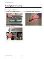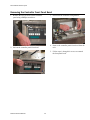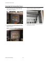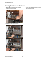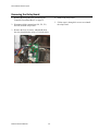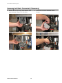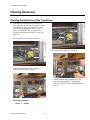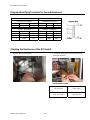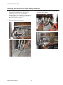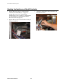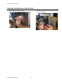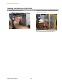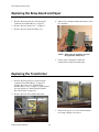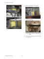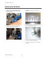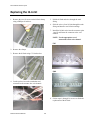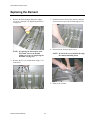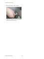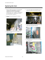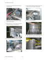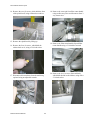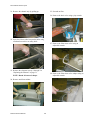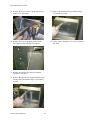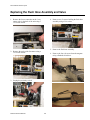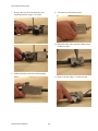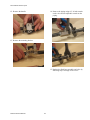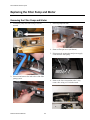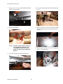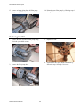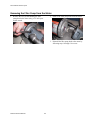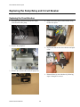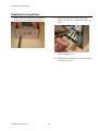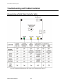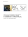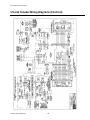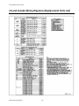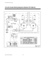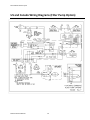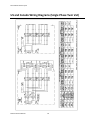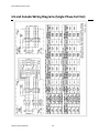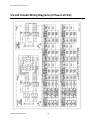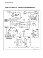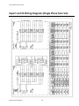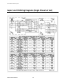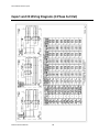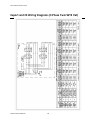
1
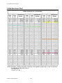
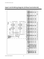
Solstice Electric Fryers SE Series Service Manual L22-330 R1 (10/12) Pitco Solstice Electric Fryers Notice In the event of problems or questions about your order, contact the Pitco Frialator factory at (603) 225-6684. In the event of problems or questions about your equipment, contact the Pitco Frialator Authorized Service and Parts representative (ASAP) covering your area, or contact Pitco at the numbers listed above. MAILING ADDRESS Pitco Frialator P.O. Box 501 Concord, NH 03302-0501 SHIPPING ADDRESS Pitco Frialator 10 Ferry Street Concord, NH 03301 EQUIPMENT REFERENECE INFORMATION Model #: __________________________ Serial #: __________________________ Date Purchased: ___________________ SE Series Service Manual 2 Pitco Solstice Electric Fryers Table of Contents Serial Numbers ............................................................................................................ 5 Theory of Operation .................................................................................................... 7 Fryer Components Operation.............................................................................................................. 8 Heating System ................................................................................................................................... 8 Hi-Limit System.................................................................................................................................. 8 Filter System ....................................................................................................................................... 9 SE Model .................................................................................................................... 10 Accessing Fryer for Servicing ............................................................................................................ 11 Powering Down the Unit .................................................................................................................. 11 Removing the Controller Front Panel Bezel ..................................................................................... 12 Removing the Entrance Box Covers ................................................................................................. 13 Removing the Entrance Box Wire Guard ......................................................................................... 14 Removing the Relay Board ............................................................................................................... 15 Removing Solid State Thermostat (If Necessary) ............................................................................ 16 Checking Resistance ........................................................................................................................... 17 Checking the Resistance of the Transformer .................................................................................... 17 Diagram Identifying Terminals for Second Resistance .................................................................... 18 Checking the Resistance of the DVI Switch ..................................................................................... 18 Checking the Resistance of the Safety Contactor ............................................................................. 19 Checking the Resistance of the HD Contactor ................................................................................. 20 Checking the Resistance of the Hi-Limit .......................................................................................... 21 Checking the Resistance of the Probe ............................................................................................... 22 Replacing the Relay Board and Paper .............................................................................................. 23 Replacing the Transformer ................................................................................................................ 23 Replacing the DVI Switch .................................................................................................................. 25 Replacing the Safety Contactor ......................................................................................................... 26 Replacing the HD Contactor .............................................................................................................. 27 Replacing the Probe ............................................................................................................................ 28 Replacing the Hi-Limit ....................................................................................................................... 30 Replacing the Element ........................................................................................................................ 31 Replacing the Tank ............................................................................................................................. 33 Filter System .............................................................................................................. 38 Replacing the Flush Hose Assembly and Valve ............................................................................... 39 Replacing the Filter Pump and Motor .............................................................................................. 42 Removing the Filter Pump and Motor .............................................................................................. 42 Replacing Seal Kit ............................................................................................................................ 44 Removing the Filter Pump from the Motor ...................................................................................... 45 Replacing the Pump Relay and Circuit Breaker ............................................................................. 46 SE Series Service Manual 3 Pitco Solstice Electric Fryers Replacing the Circuit Breaker ........................................................................................................... 46 Replacing the Pump Relay ................................................................................................................ 47 Troubleshooting and Problem Isolation ..................................................................... 48 Troubleshooting and Problem Isolation ........................................................................................... 49 Interpretation of Solid State Controller Lights ................................................................................. 49 Solid State Thermostat Field Calibration .......................................................................................... 50 Component Troubleshooting ............................................................................................................. 51 Probe ................................................................................................................................................. 51 HD Contactor .................................................................................................................................... 51 Safety Contactor................................................................................................................................ 51 Hi-Limit ............................................................................................................................................ 51 Drain Valve and Return Valve Switches .......................................................................................... 52 Transformer....................................................................................................................................... 52 Elements ............................................................................................................................................ 52 Relay Board ...................................................................................................................................... 52 Computer Control ............................................................................................................................. 53 Backup Solid State Control ............................................................................................................... 53 Probe Resistance Chart ..................................................................................................................... 55 Wiring Diagrams ........................................................................................................ 56 Simplified Wiring Diagrams .............................................................................................................. 57 US and Canada Wiring Diagrams (Controls) .................................................................................. 58 US and Canada Wiring Diagrams (Replacement Parts List) ......................................................... 59 US and Canada Wiring Diagrams (Basket Lift Option) ................................................................. 60 US and Canada Wiring Diagrams (Filter Pump Option) ............................................................... 61 US and Canada Wiring Diagrams (Single Phase Twin Vat) .......................................................... 62 US and Canada Wiring Diagrams (Single Phase Full Vat) ............................................................ 63 US and Canada Wiring Diagrams (3 Phase Full Vat) ..................................................................... 64 Export and CE Wiring Diagrams (Filter Pump Option) ................................................................ 65 Export and CE Wiring Diagrams (Single Phase Twin Vat) ........................................................... 66 Export and CE Wiring Diagrams (Single Phase Full Vat) ............................................................. 67 Export and CE Wiring Diagrams (3 Phase Full Vat) ...................................................................... 68 Export and CE Wiring Diagrams (3 Phase Twin WYE Vat) ......................................................... 69 Export and CE Wiring Diagrams (3 Phase Twin Delta Vat) .......................................................... 70 Notes ..................................................................................................................................................... 71 SE Series Service Manual 4 Pitco Solstice Electric Fryers Serial Numbers SE Series Service Manual 5 Pitco Solstice Electric Fryers SE Series Service Manual 6 Pitco Solstice Electric Fryers Theory of Operation SE Series Service Manual 7 Pitco Solstice Electric Fryers Fryer Components Operation The SE fryer components function in specific order of operation. Knowing and understanding the sequence of fryer and components operation enables you to diagnose equipment failure more accurately. Heating System The unit is connected to line voltage: If Fuse F1 on the relay board is good: The A.C. indicator is illuminated. The controller is supplied with 24 VAC. With the drain valve handle closed, the proximity switch supplies 24 VAC to the drain valve interlock (DVI) input at the controller. 24 VAC is at the Side On (SO) relay COM contact. The controller is turned ON: The SO indicator on the relay board is illuminated. The SO relay is energized, closing the circuit. The safety (SO) contactor energizes if the hi-limit is not tripped. With the roll out switch and hi-limit in the closed position, the ignition module receives 24VAC at terminal 6 (24 VAC). Hi‐Limit System If the hi-limit trips: The SO and HD contactors lose 24 VAC supply and the HFB loses 24 VAC. The computer displays “HEATING”. The HD lamp is illuminated on the Back-up T-stat and the HFB lamp is not illuminated. After the hi-limit resets (unit cools to 375°F ±20°F (191°C ±20°C)), turn the controller off and then back on for the unit to heat. SE Series Service Manual 8 Pitco Solstice Electric Fryers Filter System Opening the RED return valve handle, does the following: Opens the return valve to that vat. Closes the pump proximity switch causing the “pump run” relay to be energized. Starts the pump motor. Closing the return valve handle de-energizes the relay and the pump motor stops running and the return valve closes. The pump system is equipped with a circuit breaker which de-energizes the system and the heat tape in the event of over current. The circuit breaker must be in the “ON” position for the pump and heat tape to operate. NOTE: Circuit Breaker should remain in the “ON” position at all times. The return piping system may be provided with optional heat tape to prevent solidification of solid shortening. The heat tape is low wattage and is on constantly to maintain liquid shortening in the line. SE Series Service Manual 9 Pitco Solstice Electric Fryers SE Model SE Series Service Manual 10 Pitco Solstice Electric Fryers Accessing Fryer for Servicing Powering Down the Unit 1. Press the OFF button 3. Unplug all power cord and disconnect power. on control panel. 2. Slide button to solid state. SE Series Service Manual 11 Pitco Solstice Electric Fryers Removing the Controller Front Panel Bezel 1. Remove the two (2) screws on the controller panel using a Phillips screwdriver. 3. Disconnect the controller wiring harness. 4. Remove the controller panel front bezel from the unit. 2. Pull out the controller panel front bezel. 5. Follow steps 1 through 4 in reverse to reattach the front panel bezel. SE Series Service Manual 12 Pitco Solstice Electric Fryers Removing the Entrance Box Covers 3. Remove the two (2) screws on the entrance box upper cover using a Philips screwdriver. 1. Remove the two (2) screws on the entrance box lower cover located on the left side of the unit using a Philips screwdriver. 2. Remove the four (4) screws entrance box lower cover located on the right side of the unit using a Philips screwdriver. SE Series Service Manual 13 4. Follow steps 1 through 3 in reverse to reinstall the entrance box covers. Pitco Solstice Electric Fryers Removing the Entrance Box Wire Guard 3. Follow steps 1 through 2 in reverse to reinstall the entrance wire guard. 1. Remove the two (2) screws on the wire guard using a 5/16 inch hex wrench. 2. Slide the wire guard down to remove. SE Series Service Manual 14 Pitco Solstice Electric Fryers Removing the Relay Board 4. Remove the relay board. 1. Remove the front panel. See “Removing the Controller Front Panel Bezel” on page 12. 5. Follow steps 1 through 4 in reverse to reinstall the relay board. 2. Disconnect all the connections (J41, J35, J32, and J34) from the relay board. 3. Remove the four (4) screws, which hold down the relay board bracket, using a 5/16 inch socket. SE Series Service Manual 15 Pitco Solstice Electric Fryers Removing Solid State Thermostat (If Necessary) 1. Remove the two (2) screws, which hold the solid state thermostat, using a 5/16 inch socket. SE Series Service Manual 16 2. Disconnect solid state thermostat control harness. Pitco Solstice Electric Fryers Checking Resistance Checking the Resistance of the Transformer 1. Disconnect all electrical power. Remove the front panel (see “Removing the Controller Front Panel Bezel” on page 12), entrance box covers (see “Removing the Entrance Box Covers” on page 13), and entrance box wire guard (see “Removing the Entrance Box Wire Guard” on page 14). 2. Disconnect the secondary side terminals. 4. Disconnect the primary side terminals. 3. Connect the multimeter to the secondary terminals and check the resistance. 5. Connect the black lead of multimeter to the primary terminal marked “5”and check the resistance readings of taps in following chart on page 18. Secondary Terminals .7 ohms =+/- 20ohms SE Series Service Manual 17 Pitco Solstice Electric Fryers Diagram Identifying Terminals for Second Resistance PP10429 Secondary Resistance TAP Volts Resistance 10 ‐ 6 24V 0.7 PP10428 Secondary Resistance TAP Volts Resistance 10 ‐ 6 24V 0.6 Primary Resistance Volts Resistance 240V 30.4 208V 25.3 120V 9.9 Primary Resistance Tap Volts Resistance 5 ‐ 1 480V 119.5 5 ‐ 2 440V 107.7 5 ‐ 3 380V 90.2 Tap 5 ‐ 1 5 ‐ 2 5 ‐ 3 Checking the Resistance of the DVI Switch 2. Connect the multimeter to the DVI leads and check the resistance. 1. Remove the DVI connection. DVI Resistance Table SE Series Service Manual 18 Valve Closed Valve Open Near Zero Ohm Open Circuit Pitco Solstice Electric Fryers Checking the Resistance of the Safety Contactor 1. Remove the front panel (see “Removing the Controller Front Panel Bezel” on page 12), entrance box covers (see “Removing the Entrance Box Covers” on page 13), and entrance box wire guard (see “Removing the Entrance Box Wire Guard” on page 14). 2. Disconnect the coil connections. Below SE Series Service Manual 19 3. Connect the multimeter to the coil connections and check the resistance. Pitco Solstice Electric Fryers Checking the Resistance of the HD Contactor 1. Remove the front panel (see “Removing the Controller Front Panel Bezel” on page 12), entrance box covers (see “Removing the Entrance Box Covers” on page 13), and entrance box wire guard (see “Removing the Entrance Box Wire Guard” on page 14). 2. Remove the two (2) screws from the coil using a Philips screwdriver. SE Series Service Manual 20 3. Connect the multimeter to the connections and check the resistance. Pitco Solstice Electric Fryers Checking the Resistance of the Hi‐Limit 2. Connect the multimeter to the Hi-limit leads and check the resistance. 1. Remove the Hi-Limit connection. SE Series Service Manual 21 Pitco Solstice Electric Fryers Checking the Resistance of the Probe 1. Remove the probe connection. 2. Connect the multimeter to the thermostat leads and check the resistance. See “Probe Resistance Chart” on page 55. SE Series Service Manual 22 Pitco Solstice Electric Fryers Replacing the Relay Board and Paper 4. Remove the existing insulator and replace with a new insulator. 1. Remove the front panel. See “Removing the Controller Front Panel Bezel” on page 12. 2. Remove the relay board. See “” on page 15. 3. Remove the relay board and flip it over. NOTE: Make sure the insulator does not have puncture marks in it. 5. Follow steps 1 through 2 to finish the replacement of relay board and paper. Replacing the Transformer 1. Remove the front panel (see “Removing the Controller Front Panel Bezel” on page 12), entrance box covers (see “Removing the Entrance Box Covers” on page 13), and entrance box wire guard (see “Removing the Entrance Box Wire Guard” on page 14). 2. Remove the four (4) terminal connections. 3. Remove the two (2) screws on the transformer box using a Philips screw driver. SE Series Service Manual 23 Pitco Solstice Electric Fryers 4. Remove transformer box from the unit. Transformer Wiring NOTE: Wire according to the appropriate voltage. 5. Follow steps 1 through 3 in reverse to install the new transformer. SE Series Service Manual 24 Pitco Solstice Electric Fryers Replacing the DVI Switch 3. Unfasten the switch harness from the wire channel. 1. Remove the two (2) screws, which hold the proximity sensor on the drain handle, using a flathead screwdriver. 4. Remove the switch from mounting plate using a narrow tip flathead screwdriver. 2. Loosen the two (2) screws, which hold the actuator, using a Philips screwdriver. 5. Replace the DVI switch ensuring a 1/4 inch gap between the actuator and the magnet. 6. Follow steps 1 through 3 in reverse to install a new DVI. SE Series Service Manual 25 Pitco Solstice Electric Fryers Replacing the Safety Contactor 1. Remove the six (6) screws from the safety contactor using a flathead screwdriver. 3. Remove the bottom screw on the safety contactor using a Philips screwdriver. 4. Remove the safety contactor. Wires to Safety Contactor Connections Table Safety Contactor Connections Wires L1 (top) 1B L2 (top) 2B L3 (top) 3B T1(bottom) 1D T2 (bottom) 2D T3 (bottom) 3D 2. Loosen the top screw on the safety contactor using a Philips screwdriver. SE Series Service Manual 5. Follow steps 1 through 10 in reverse to finish the replacement of the new safety contactor. 26 Pitco Solstice Electric Fryers Replacing the HD Contactor 1. Remove the six (6) screws from the HD contactor using a Philips screwdriver. 4. Remove the bottom screw on the mounting plate using a Philips screwdriver. 2. Remove the top screw on the mounting plate behind the HD contactor using a Philips screwdriver. 5. Remove the HD contactor. 3. Cut the zip tie under the HD contractor to access the bottom screw on the plate. 6. Remove the two (2) screws from the plate using a Philips screwdriver. 7. Follow steps 1 through 6 in reverse to finish the replacement of the new HD contactor. SE Series Service Manual 27 Pitco Solstice Electric Fryers Replacing the Probe 1. Remove the basket hanger. 4. Remove the probe nut with 7/16 inch socket. 2. Remove one (1) of the screws from probe clamps using a Phillips screwdriver. 5. Cut the probe wires at the termination end connected to the entrance box wire channel. 3. Loosen the other screw on the probe clamps, but do not remove it. Turn the rear probe clamp down and remove all three probe clamp pieces. 6. Pull the probe and wires through the tank fitting. SE Series Service Manual 28 7. Slide the probe wires through the probe nut and ferrule, and then slide the probe nut and ferrule through the probe. Pitco Solstice Electric Fryers 8. Slide the probe wires through the tank fitting. Split Left Tank Right Tank Doors 9. Install the connectors onto the wires (black with black, and white with white). 11. Follow steps 1 through 4 in reverse to finish the replacement of the probe. NOTE: Be sure to leave at least 1 inch of probe exposed below probe clamps. 10. Fasten the connectors to the wire channel. NOTE: Use the appropriate set of connections on the wire channel. Full SE Series Service Manual 29 Pitco Solstice Electric Fryers Replacing the Hi‐Limit 1. Remove the two (2) screws on the hi-limit clamp using a Phillips screwdriver. 5. Pull the hi-limit and wires through the tank fitting. 6. Slide the wires of new hi-limit through the tank fitting and install a new hi-limit cartridge. 7. Install the hi-limit wires into the connector (pins 1 and 2) and fasten the connector to the wire channel. NOTE: Use the appropriate set of connections on the wire channel. Full 2. Remove the clamps. 3. Remove the hi-limit using a 7/8 inch socket. Split Left Tank Right Tank 4. Cut the probe wires at the termination end connected to the entrance box wire channel. Doors 8. Follow steps 1 through 3 in reverse to finish the replacement of the hi-limit. SE Series Service Manual 30 Pitco Solstice Electric Fryers Replacing the Element 1. Remove the basket hanger and probe clamps (see steps 1 through 3 in “Replacing the Probe” on page 28). 3. Push down on the front of the element, and pull out the back to expose the element supply wires. 4. Disconnect the element supply wires. NOTE: If replacing the left element of the SE14 tank, remove the hi-limit clamps (see step 1 in “Replacing the Hi-Limit” on page 30). NOTE: Do not let the wires fall back through the element mounting block. 2. Remove the five (5) element bolts using a 7/16 inch socket. 5. Remove the element. SE Series Service Manual 31 Pitco Solstice Electric Fryers 6. Replace the element o-rings, if needed. 7. Follow steps 1 through 5 in reverse to finish the replacement of the new element. SE Series Service Manual 32 Pitco Solstice Electric Fryers Replacing the Tank 1. Remove all the front panels (see “Removing the Controller Front Panel Bezel” on page 12), entrance box covers (see “Removing the Entrance Box Covers” on page 13), and entrance box wire guards (see “Removing the Entrance Box Wire Guard” on page 14). 4. Loosen the entrance box heat shield sides (top and bottom) using a 5/16 inch hex wrench. 2. Remove the top deck using a 5/16 inch hex wrench. 5. Slide the heat shield sides in enough to clear the cabinet sides during tank removal. 3. Remove the top deck heat shield using a 5/16 inch hex wrench. 6. Disconnect and remove the power cords from the entrance box. SE Series Service Manual 33 Pitco Solstice Electric Fryers 7. Loosen the four (4) drain elbow bolts using a 9/16 inch socket. 11. Disconnect the following connectors at the wire channel: DVI switch, probes, and hi-limit. 8. Slide the entire drain line assembly off of the drain extension nipples. 12. Remove the basket hangers. 9. Remove the four (4) screws that hold down the entrance box using a 5/16 inch socket. 13. Remove the six (6) screws, which hold the back of the splash back, using a 5/16 inch socket. 10. Disconnect the filter pump box power supply. SE Series Service Manual 34 Pitco Solstice Electric Fryers 14. Remove the two (2) screws, which hold the front of the splash back, using a flathead screwdriver. 15. Remove the splash back by lifting up. 19. Remove the filter return handle clip and filter return handle using a 5/16 inch hex wrench. 16. Remove the four (4) screws, which hold the cabinet back cover, using a 5/16 inch socket. 20. Remove the six (6) screws (front and back), which hold the tank to the cabinet, using with a 5/16 inch socket. 17. Disconnect all return hoses from the tank being replaced using an adjustable wrench. SE Series Service Manual 18. Remove the cotter pin from filter return handle using needle-nose pliers and disconnect from 3way return valve. 35 Pitco Solstice Electric Fryers 21. Remove the channel strip by pulling up. 25. Set tank on floor. 26. Remove the drain valve using a pipe wrench. 22. Score the silicon sealer between the tanks using a flathead screwdriver or utility knife. 27. Remove the filter return valve using an adjustable wrench. 23. Remove the elements in steps 1 through 5 in “Replacing the Element” on page 31. 28. Remove the filter return valve adapter using an adjustable wrench. NOTE: Retain all removed clamps. 24. Remove tank from cabinet. SE Series Service Manual 36 Pitco Solstice Electric Fryers 29. Remove the four (4) screws on the entrance box using a 5/16 inch socket. 33. Remove the entrance box heat shields using a 5/16 inch hex wrench. 30. Remove the two (2) mounting screws on the wire channel using a Phillips screwdriver. 34. Follow steps 1 through 33 in reverse to install a new tank. 31. Remove the entrance box and wire channel assembly as one piece. 32. Remove the entrance box support brackets from entrance box heat shields using a 5/16 inch hex wrench. SE Series Service Manual 37 Pitco Solstice Electric Fryers Filter System SE Series Service Manual 38 Pitco Solstice Electric Fryers Replacing the Flush Hose Assembly and Valve 1. Remove the lower connection at the 3-way return valve in the back of the unit using a 15/16 inch wrench. 4. Remove two (2) screws holding the flush hose assembly using a 5/16 socket. 5. Remove the flush hose assembly. 2. Remove the male quick disconnect using a 15/16 inch wrench. 6. Remove the four (4) screws from the magnets using a flathead screwdriver. 3. Unplug the proximity switch. SE Series Service Manual 39 Pitco Solstice Electric Fryers 7. Remove the two (2) screws from the valve mounting brackets using a 5/16 socket. 9. Lift bracket out and slide forward. 10. Bend down tabs of the stem nut washer using a needle-nose plier. 8. Slide the bracket to the back of the assembly. 11. Remove the nut using a 7/16 inch wrench. SE Series Service Manual 40 Pitco Solstice Electric Fryers 12. Remove the handle. 14. Remove the piping using a 15/16 inch wrench on the valve and an adjustable wrench on the piping. 13. Remove the mounting bracket. 15. Replace the flush hose assembly and valve by following steps 1 through 14 in reverse. SE Series Service Manual 41 Pitco Solstice Electric Fryers Replacing the Filter Pump and Motor Removing the Filter Pump and Motor 3. Pull out pump inlet tube. 1. Loosen the pump inlet tube using a crescent wrench. 4. Remove filter pan cover (not shown). 5. Disconnect the connections and power supply cords from the filter pump. 2. Unscrew and remove the inlet valve of the filter pump system. 6. Remove the lower connection at the 3-way return valve using a 15/16 inch wrench. SE Series Service Manual 42 Pitco Solstice Electric Fryers 7. Remove one (1) screw, which holds the bracket, using a 5/16 inch socket. 10. Lower the filter pump to the floor and then pull it out. 8. Remove the bracket. 11. Remove the three (3) bolts on the bottom of the filter pump base using a 1/2 inch open-ended wrench. NOTE: The filter pump will fall to the floor once the pins are pulled out. It is recommended that you brace the pump and motor before pulling out the pins. 12. Remove two (2) screws on back of filter pump using a 5/16 inch socket. 9. Turn down the pins and then pull them out. SE Series Service Manual 43 Pitco Solstice Electric Fryers 13. Remove existing piping from old filter pump using two adjustable wrenches. 14. Reinstall a new filter pump by following steps 1 through 13 in reverse. Replacing Seal Kit 1. Remove the four (4) bolts on filter pump using 7/16 inch open-ended wrench. 3. Replace the seal. 4. Reinstall the filter pump head to the motor by following steps 1 through 2 in reverse. 2. Remove the filter pump head. SE Series Service Manual 44 Pitco Solstice Electric Fryers Removing the Filter Pump from the Motor 2. Remove the filter pump head from the motor. 1. Remove the two (2) bolts holding the filter pump head to the motor using a 1/2 inch openended wrench. 3. Reinstall the filter pump head to the motor by following steps 1 through 2 in reverse. SE Series Service Manual 45 Pitco Solstice Electric Fryers Replacing the Pump Relay and Circuit Breaker Replacing the Circuit Breaker 4. Remove all wires on the circuit breaker using needle-nose pliers. 1. Disconnect the connections and power supply cords from the filter pump. 2. Remove the pump box. 5. Squeeze the tabs on the circuit breaker and push it out. 3. Remove the circuit breaker from the pump box. 6. Reinstall the new circuit breaker by following steps 1 through 5 in reverse. SE Series Service Manual 46 Pitco Solstice Electric Fryers Replacing the Pump Relay 2. Remove all wires on the pump relay using needle-nose pliers. See “Wiring Schematics” on page 57. 1. Remove the two (2) screws, which hold the pump relay, using a Phillips screwdriver. 3. Remove the pump relay. 4. Reinstall the new pump relay by following steps 1 through 2 in reverse. SE Series Service Manual 47 Pitco Solstice Electric Fryers Troubleshooting and Problem Isolation SE Series Service Manual 48 Pitco Solstice Electric Fryers Troubleshooting and Problem Isolation Interpretation of Solid State Controller Lights SE Series Service Manual 49 Pitco Solstice Electric Fryers Solid State Thermostat Field Calibration If field calibration is necessary, follow these steps: 1. Allow appliance to heat to set point, and then allow 30 minutes to stabilize. 2. Measure the vat center oil temperature and compare this with the knob pointer scale. 3. To reposition the knob, pry off the cap of the knob with a sharp knife blade. 4. Without turning the shaft, loosen the 5/16-inch compression nut and pull the knob off. 5. Re-install the knob with the pointer at the temperature indicated on the test thermometer. 6. Tighten the 5/16-inch compression nut and install the cap. SE Series Service Manual 50 Pitco Solstice Electric Fryers Component Troubleshooting The following sections provide troubleshooting information for the fryer components. Probe The resistance of the probe changes as the temperature changes. The resistance decreases as the temperature rises. The lower the temperature, the greater the resistance change is per degree of temperature change. As the temperature approaches the working range of the probe, the resistance change becomes more linear. If the probe is suspect, check its resistance and the oil temperature (as close to the probe as possible) at which it was taken. Compare these values to the values in the “Probe Resistance Chart” on page 55. If the probe returns an open circuit or a 0 Ω reading, replace it. If the resistance varies more than 30 Ω when checked in the range of 325°F to 375°F (163°C to 191°C), the probe gives a false temperature reading on the computer. Calibrate the probe up to 10°F or replace it; however, the probe continues to operate at a slightly higher or lower temperature. See “Probe Resistance Chart” on page 55. Allow the oil to cool and check the probe resistance at a lower temperature. Looking at the probe resistance chart, a greater resistance variation is tolerated at a lower temperature. HD Contactor The HD contactor has a 24 VAC coil and energizes when the correct voltage is supplied to the coil. When energized, the contacts close, allowing current to flow through the elements. The coil resistance is 192 Ω out of current. Safety Contactor Check the coil with an Ω meter. The resistance should be approximately 3 Ω to 6 Ω out of circuit. If it does not have this resistance, it should be changed. Hi‐Limit The hi-limit switch is a closed switch until the temperature at the hi-limit bulb reaches 425°F ±20°F (232°C ±20°C). The oil temperature needs to drop approximately 45°F (7°C) before it resets. If it does not reset after the oil has cooled, it is defective. WARNING: THIS TEST SHOULD BE PERFORMED BY A QUALIFIED TECHNICIAN ONLY! MONITOR THE FRYER CLOSELY. THIS TEST WILL CAUSE THE OIL TO HEAT PAST THE NORMAL OPERATING TEMPERATURE AND CAN CAUSE DAMAGE TO THE MACHINE AND ITS OPERATOR IF CARE IS NOT TAKEN. WARNING: THIS TEST WILL CAUSE THE ELEMENTS TO HEAT CONTINUOUSLY. REMOVE TEST RESISTOR WHEN TEST IS COMPLETE. LEAVING THE TEST RESISTOR IN THE FRYER COULD CAUSE DAMAGE TO THE EQUIPMENT AND/OR PERSONAL INJURY. SE Series Service Manual 51 Pitco Solstice Electric Fryers To test the hi-limit, use a 2kς - 5 kς resistor to simulate a 230°F - 275°F temperature. This causes the elements to heat continuously until the hi-limit trips or the fryer is turned off. If testing with the computer, plug the resistor in at connector J41 behind the front panel. If testing with the back-up thermostat behind the door, plug the resistor in at connector J43 behind the front panel. If the switch does not trip between the prescribed limits, it is defective and should be replaced. Once tripped, the switch cannot be reset until the oil has cooled to approximately 375°F ±20°F. If the switch does not reset after oil has cooled, it is defective. Drain Valve and Return Valve Switches These switches are a magnetically operated proximity switches. When the BLUE drain valve handle is moved to the open position, the actuator moves away from the switch causing the switch to open. When the drain valve is closed, the switch closes. Opening the RED filter return valve handle closes the proximity switch, causing the “pump on” relay to be energized; the pump begins to pump. Closing the filter return valve handle opens the proximity switch, causing the relay to de-energize and the pump to stop pumping. These switches can be checked with a Ω meter. When the switch is closed, there should be continuity. The normal gap between the actuator and the sensor switch on the valve handle is 1/8 inch to 1/4 inch (3 mm to 6 mm). Transformer The transformer is a multiple AC input voltage and 24 VAC output voltage. It can be checked by reading the input and output voltages. A quick check for 24 VAC is done at the relay board behind the front panel. The AC indicator is illuminated if the F1 fuse is good and the board is receiving 24 VAC. Elements Each element has three coils. Check all the element coils out of circuit with an Ω meter. The resistance should correspond to the following: 208 Volt Element 240 Volt Element 14.1-16.4 Ω 18.8-21.8 Ω If the resistance is outside of the rating, the element needs to be changed. Also check for continuity to ground on each end of the suspect element. There should be no continuity to ground. Relay Board NOTE: J connectors are marked on the relay board. With 24 VAC supplied to pin #2 at connector J35 and a good F1 fuse, the relay board has a 24 VAC output at pin #2 on connectors J33 and J34 and the AC indicator is illuminated. When the board receives a 24 VDC SO input at pin #7 on connector J31 or J33, the SO indicator is illuminated, the SO relay is energized, and there is a 24 VAC output at pin #4 on connector J32. SE Series Service Manual 52 Pitco Solstice Electric Fryers When the board receives a 24 VDC HD input at pin #6 on connector J31 or J33, the HD indicator is illuminated, the HD relay is energized and there is continuity between pin #1 and pin #2 at connector J32. Computer Control NOTE: All controller test points are at connector P/J1 (closest connector to the controller). With 24 VAC supplied to pin #1(24 VAC supply) and pin #5 (24 VAC input from DVI), the display reads “READY”. When the controller is turned on, there is a 24 VDC output at pin #9 (SO). When the controller calls for heat, there is a 24 VDC output at pin #8 (HD) and a 24 VAC input at pin #6 (HFB). If the HD contactor does not pull in, this indicates a break in the HD circuit. To correct, do the following: 1. Check the hi-limit switch. Is it open or tripped? 2. Check the HD relay on the relay board. Is the HD relay energized, continuity through COM and NO contacts? If display reads “PROBE OP” “OPEN”, Ω test the temperature probe. Check the wires and connectors between the probe and controller for continuity. If display reads “SYSTEM” ‘FAILURE”, Ω test the temperature probe, and the wires and connectors between the probe and controller for a short. If display reads “DRAINING” “TURN OFF”, verify that the drain valve is closed, check the proximity switch on the drain valve, turn the fryer off, and then turn the fryer on. Backup Solid State Control The 24 VAC supply passes through the solid state back-up transfer switch to the computer. If the transfer switch is set to back-up or if the back-up controller has been unplugged, the primary controller will not work. A jumper must be installed on the relay board (connection J33, pin #2 to pin #10) to allow the primary controller to function if the back-up controller is removed. 24 VAC is supplied to the controller at pin #1 (24 VAC supply) and pin #5 (24 VAC input from DVI). When the controller turned on, there is a 24 VDC output at pin #9 (SO) and the green indicator is illuminated. When the controller calls for heat, there is a 24 VDC output at pin #8 (HD), the yellow indicator on the left is illuminated, and there is a 24 VAC input at pin #6 (HFB). When the controller receives the 24 VAC input at pin #6, the yellow indicator on the right is illuminated. If the controller does not receive the 24 VAC input at pin #6, the indicator is not illuminated. This indicates a break in the HD or HFB circuit. To correct, do the following: 1. Check the hi-limit switch. Is it open or tripped? 2. Check the HD relay on the relay board. Is the HD relay energized, continuity through COM and NO contacts? SE Series Service Manual 53 Pitco Solstice Electric Fryers If the green and yellow indicators on the left illuminate on and off when the controller is turned on, this indicates an open or shorted probe or wires in between the probe and the controller. If none of the indicators illuminate when the controller is turned on, verify that the drain valve is closed and that the magnetic proximity switch has continuity when the drain valve is closed. Also verify that there is 24 VAC at pin #1 (24 VAC supply) and pin #5 (24 VAC input from DVI). SE Series Service Manual 54 Pitco Solstice Electric Fryers Probe Resistance Chart Probe Resistance in 5°F Increments. Probe Temp (°F) 10 15 20 25 30 35 40 45 50 55 60 65 70 75 80 85 90 95 100 105 110 115 120 125 130 135 140 145 150 155 160 165 170 Probe Temp (°C) -12.2 -9.4 -6.7 -3.9 -1.1 1.7 4.4 7.2 10.0 12.8 15.6 18.3 21.1 23.9 26.7 29.4 32.2 35.0 37.8 40.6 43.3 46.1 48.9 51.7 54.4 57.2 60.0 62.8 65.6 68.3 71.1 73.9 76.7 Resistance (Ohms) 562734 483875 417167 360589 312474 271446 236370 206311 180491 158252 139055 122489 108051 95539 84644 75136 66823 59540 53146 47523 42569 38195 34328 30902 27862 25161 22755 20610 18695 16981 15446 14069 12823 Probe Temp (°F) 175 180 185 190 195 200 205 210 215 220 225 230 235 240 245 250 255 260 265 270 275 280 285 290 295 300 305 310 315 320 325 330 335 Probe Temp (°C) 79.4 82.2 85.0 87.8 90.6 93.3 96.1 98.9 101.7 104.4 107.2 110.0 112.8 115.6 118.3 121.1 123.9 126.7 129.4 132.2 135.0 137.8 140.6 143.3 146.1 148.9 151.7 154.4 157.2 160.0 162.8 165.6 168.3 Resistance (Ohms) 11719 10716 9812 8995 8255 7586 6979 6427 5926 5470 5055 4675 4329 4013 3723 3458 3214 2991 2785 2597 2422 2262 2113.9 1977.3 1851.0 1734.3 1626.1 1525.9 1433.0 1346.7 1266.6 1192.1 1122.8 Probe Temp (°F) 340 345 350 355 360 365 370 375 380 385 390 395 400 405 410 415 420 425 430 435 440 445 450 455 460 465 470 475 480 485 490 495 500 Probe Temp (°C) 171.1 173.9 176.7 179.4 182.2 185.0 187.8 190.6 193.3 196.1 198.9 201.7 204.4 207.2 210.0 212.8 215.6 218.3 221.1 223.9 226.7 229.4 232.2 235.0 237.8 240.6 243.3 246.1 248.9 251.7 254.4 257.2 260.0 Resistance (Ohms) 1058.23 998.09 942.00 889.67 840.78 795.10 752.38 712.41 674.95 639.87 606.96 576.09 547.09 519.86 494.24 470.16 447.49 426.13 406.02 387.04 369.14 352.24 336.29 321.21 306.94 293.46 280.69 268.61 257.15 246.30 236.00 226.24 216.96 NOTE: Resistance, of either probe lead, to the frame of the appliance should read as “open’ on the meter. Typically this is 1Meg ohms or more. °C = 5/9 (°F-32) °F = (9/5 * °C) +32 SE Series Service Manual 55 Pitco Solstice Electric Fryers Wiring Diagrams SE Series Service Manual 56 Pitco Solstice Electric Fryers Simplified Wiring Diagrams SE Series Service Manual 57 Pitco Solstice Electric Fryers US and Canada Wiring Diagrams (Controls) SE Series Service Manual 58 Pitco Solstice Electric Fryers US and Canada Wiring Diagrams (Replacement Parts List) SE Series Service Manual 59 Pitco Solstice Electric Fryers US and Canada Wiring Diagrams (Basket Lift Option) SE Series Service Manual 60 Pitco Solstice Electric Fryers US and Canada Wiring Diagrams (Filter Pump Option) SE Series Service Manual 61 Pitco Solstice Electric Fryers US and Canada Wiring Diagrams (Single Phase Twin Vat) SE Series Service Manual 62 Pitco Solstice Electric Fryers US and Canada Wiring Diagrams (Single Phase Full Vat) SE Series Service Manual 63 Pitco Solstice Electric Fryers US and Canada Wiring Diagrams (3 Phase Full Vat) SE Series Service Manual 64 Pitco Solstice Electric Fryers Export and CE Wiring Diagrams (Filter Pump Option) SE Series Service Manual 65 Pitco Solstice Electric Fryers Export and CE Wiring Diagrams (Single Phase Twin Vat) SE Series Service Manual 66 Pitco Solstice Electric Fryers Export and CE Wiring Diagrams (Single Phase Full Vat) SE Series Service Manual 67 Pitco Solstice Electric Fryers Export and CE Wiring Diagrams (3 Phase Full Vat) SE Series Service Manual 68 Pitco Solstice Electric Fryers Export and CE Wiring Diagrams (3 Phase Twin WYE Vat) SE Series Service Manual 69 Pitco Solstice Electric Fryers Export and CE Wiring Diagrams (3 Phase Twin Delta Vat) SE Series Service Manual 70 Pitco Solstice Electric Fryers Notes SE Series Service Manual 71 Pitco Solstice Electric Fryers In the event of problems with or questions about your order, please contact Pitco Frialator factory at: 603225-6684 World Wide www.pitco.com In the event of problems with questions about your order, please contact Pitco Frialator Authorized Service and Parts representative (ASAP) covering your area or contact Pitco at the number listed to the left. MAILING ADDRESS – P.O. BOX 501 CONCORD, NH 03302-0501 SHIPPING ADDRESS – 10 FERRY STREET, CONCORD, NH 03301 SE Series Service Manual 72