1
■SI*.
^r'-:
''Vj
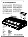
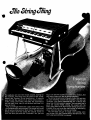
.The audience will turn their heads around, looking for
the orchestra, when they hear the sound of the revolu
tionary new Freeman String Symphonizer. It supports
your act with the sounds of an entire string sectionviolins, violas, even cellos. And after the performance
you can pack it up, carry it out the door and load it in
your car trunk.
Play a one-finger melody for a solo violin effect. Play
tring quartets with just one hand. Two hands can sound
Ae an entire string section. Want more? The polyvoice
design makes each key sound like several violins at
once. So when you press the "Ensemble" tab, just one
finger can play the sounds c$^;^
one chord comes on like ari^rftire^yrhJDhony;
And
The String Symphonizer's Reverb control lets you turn
on some haunting concert hall acoustics. And you can
"animate" your sound automatically for a vibrato that
takes fine violinists years to master. You can even play a
good old country fiddle, sliding the sound with the
Glide pedal. Best of all, the Freeman String Symphonizer
is tough. When you're on the road, setting up and tearing
down, you can rely on it like an old friend.
The next time you go on stage, start pulling some
new strings. With the Freeman String Symphonizer. You
won't play second fiddle to anybody.
izor
FRM-S810
The oudience will turn their heads around,
The String Symphonizer's Reverb control lets
looking for the orchestra, when they hear the
you turn on some haunting concert hall acous
sound of the revolutionary new Freeman
String Symphonizer. It supports your act with
tics. And you can "animate" your sound
the sounds of an entire string section—violins,
violinists years to master. You can even play a
good old country fiddle, sliding the sound with
violas, even cellos. And after the performance
automatically for a vibrato that takes fine
you can pack it up, carry it out the door and
the Glide pedal. Best of all, the Freeman
load it in your car trunk.
String Symphonizer is tough. When you're on
Play a one-finger melody for a solo violin
effect. Play string quartets with just one hand.
Two hands can sound like an entire string sec
tion. Want more? The polyvoice design makes
the road, setting up and tearing down, you
can rely on it like an old friend.
The next time you go on stage,
start pulling some new strings. With the
each key sound like several violins at once.
Freeman String Symphonizer. You
So when you press the "Ensemble" tab, just
one finger can play the sounds of a small string
section. And one chord comes on like an
won't play second fiddle to anybody.
entire symphony.
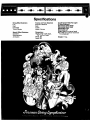
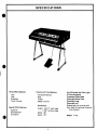
SPECIFICATIONS
String Effect Selectors
Low
High
Ensemble
Touch Vibrato
Special Effect Selectors
Sustainer
Reverberation
Animation
Volume and
Tone Selectors
Keyboard Balance
Boss
Treble
Master Volume
Dimensions:
Height, 34W (with legs),
Tk" (without legs)
Width, 38"
Depth, 23"
On-Off Switch With
Riot Light
61 Note Keyboard
Expression/Glide Pedal
Removable Music Rack
Detachable Legs
Removable Lid
Output Jack
(ro external amp)
Aux. Jack (for optional
Cordovox Tone
Cabinet)
Weight: 77 lbs.
FREEMAN STRING SYMPHONIZER
Distributed by Norlin Music Inc.
7373 N. Cicero Avenue • Lincolnwood, Illinois 60646
Specifications
String Effect Selectors
Low
High
Ensemble
Touch Vibrato
Special Effect Selectors
Sustainer
Reverberation
Animation
Volume and Tone Selectors
Keyboard Balance
Bass
Treble
Master Volume
Dimensions:
Height, 34V2" (with legs),
77/e/; (without legs)
Width, 38"
Depth, 23"
On-Off Switch With Pilot Light
61 Note Keyboard
Expression/Glide Pedal
Removable Music Rack
Detachable Legs
Removable Lid
Output Jack (to external amp)
Aux. Jack (for optional Cordovox
Tone Cabinet)
Weight: 77 lbs.
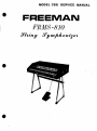
c/reeman String SympRoniz&r
MODEL CSS
SERVICE
MANUAL
FREEMAN
FRMS-810
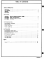
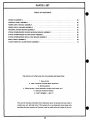
TABLE OF CONTENTS
SERVICE INFORMATION
Specifications
1
Circuit Description
*
2
Adjustments
3
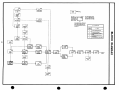
Block Diagram
4
SCHEMATICS
Drawing No.1
Glide, Tone Generators, Animation & Dividers
5
Drawing No.2
String & Touch Vibrato Keying
6
Drawing No.3
Reverb, Preamps & Expression Pedal
8
Drawing No.4
Power Supply
,
9
CHARTS & DIAGRAMS
String Symphonizer Keying Board
10
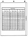
Diode Keying Chart
12
Transistor Basing Diagram
14
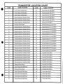
Transistor Location Chart
15
PHOTOGRAPHS
String Symphonizer Oscillator Board
16
String Symphonizer Divider & Mixing Board
17
Touch Vibrato & Glide Board
18
String Symphonizer Keying Board
19
Preamp & Reverb Board
20
Power Supply Board
21
Power Supply Chassis
22
PARTS
Parts Information
23
Parts List
24
993-024277
SPECIFICATIONS
String Effect Selectors
Low
High
Ensemble
Touch Vibrato
Special Effect Selectors
Sustainer
Reverberation
Animation
Volume and Tone Selectors
Keyboard Balance
Bass
Treble
On-Off Switch with Pilot Light
61-Note Keyboard
Expression/Glide Pedal
Removable Music Rack
Master Volume
Detachable Legs
Dimensions:
Output Jack (to external amp)
Height -34-1/2" (with legs)
7-7/8" (without legs)
Removable Lid
Aux. Jack (for optional Cordovox
Tone Cabinet)
Width - 38"
Depth - 23"
Weight: 77 lbs.
CIRCUIT DESCRIPTION
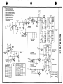
SCHEMATIC 1
GLIDE, TONE GENERATORS,
ANIMATION & DIVIDERS
There are three generator systems used — Channel 1, Channel
2 and the Top Octave Synthesizers. Channel 2 always has an
output as long as the high or low pushbuttons are on while
the TOS and Channel 1 generators have an output only when
the ensemble pushbutton is pressed.
Pressing the Glide Switch on the Expression Pedal acti
vates the Glide circuitry which de-tunes the three generator
systems by a half step.
Q1 GLIDE SWITCHER
When the Glide Switch is pressed, a ground is applied to the
Glide Switcher causing it to conduct, applying negative volt
Q20-Q23, IC4 & IC5 CHANNEL 1 & 2 MASTER
OSCILLATORS 8c DIVIDERS
The Channel 1 & 2 Master Oscillators run continuously,
producing high frequency audio signals. These signals are
then applied to their associated IC Divider where the fre
quencies are divided in half several times. The outputs of
Channel 1 & Channel 2 Dividers are then applied to the
String Keyers.
NOTE: The Channel 1 Master Oscillators, although they run
continuously, only have an output to the Dividers when the
ensemble pushbutton is on.
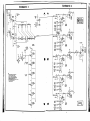
SCHEMATIC 2
STRING KEYING & VIBRATO
With the High and/or Low pushbutton on, positive voltage is
age to the bases of the TOS Glide Keyer Q2 and the Channel
applied through the emitter base junction of the C3-C6 and
1 & 2 Glide Keyer Q3.
C1-B2 Buss Drivers Q26 & Q28 to the High and Low keyswitch buss bars.
Q2, Q3 TOS GLIDE KEYER, CHANNEL 1 & 2 GLIDE
Pressing a keyswitch lowers the voltage on the base of
KEYER
Q26 and Q28, turning it on and applying positive voltage
With the Glide Switch on, negative voltage is applied to the
to the touch vibrato keying circuit. Also, positive voltage
bases of Q2 & Q3 from the Glide Switcher Q1, causing them
from the keyswitch buss bar is applied to the String Keyer
to conduct. When Q2 & Q3 conduct, negative voltage is
circuit, where audio signal from the TOS Generator and
applied to their respective oscillators shifting the frequency
Channel 1 & 2 Generators is combined and passed through
and creating the Glide effect. The TOS Glide Adjustment
the String Keyer. This combined signal is then applied to a
VR1 adjusts the amount of TOS frequency shift.
Collector Octave Preamp and then the String Preamps Q48
Q4-Q6, ICMC3 HIGH FREQUENCY MASTER OSCIL
LATOR, BUFFER, WAVE SHAPER, TOP OCTAVE
& Q49 before being sent to the Reverb Driver Q51 and the
String Emitter Follower Q52.
SYNTHESIZERS AND DIVIDERS
Q25-Q28, C3-C6 & C1-B2 BUSS DRIVERS
With the ensemble pushbutton on, the High Frequency Mas
Positive voltage from the Keyboard Balance Control VR4 is
ter Oscillator Q4, creates a high frequency signal which is
applied to the bases of Q25 & Q27, causing them to conduct
applied to the Top Octave Synthesizers IC1 & IC2 via the
which applies voltage through the emitter base junction of
Buffer Q5 and Wave Shaper Q6. Here the signal is divided to
Q26 & Q28 to the High & Low Keyswitch Buss Bars.
create twelve specific octave frequencies which are applied
to the IC Dividers IC3.These frequencies are then divided in
half several times, creating lower octave frequencies. The
outputs are then applied to the String Keyers. The Buffer
Q5 acts as an isolation stage between the Master Oscillator
Q4 and the TOS IC1 & IC2, preventing any change in
Master Oscillator frequency due to change in circuit load.
The Wave Shaper Q6 converts signal from the High Fre
quency Master Oscillator Q4 into the proper drive signal for
the TOS.
Q29-Q36 TOUCH VIBRATO KEYERS & SWITCHERS
Pressing a keyswitch lowers the voltage on the base of its
associated Buss Driver Q26 or Q28 causing it to conduct
which applies a positive voltage to the base of Touch Vibrato
Keyer Q29.
This causes Q29 to conduct which creates a pulse across
the 3 UF capacitor, lowering the voltage on the base of
Touch Vibrato Keyer Q30 and momentarily turning it off.
With the touch vibrato pushbutton on, voltage from the
collector of Q30 is applied to* the bases of the Touch Vibrato
Q7 ANIMATION DRIVER
Switchers Q31-Q36, causing them to conduct momentarily
The Animation Driver supplies the operating voltage for the
turning off the Animation Oscillators. As the 3 UF capacitor
Animation Oscillators. How hard the Driver turns on, or
charges, Touch Vibrato Keyer Q30 turns on, grounding the
how much voltage is supplied to the Animation Oscillators is
bases of the Touch Vibrato Switchers Q31-Q36. This turns
determined by the Animation Control VR2.
the Switchers off allowing the animation oscillator to resume
normal operation (see circuit description on animation oscil
Q8-Q19 ANIMATION OSCILLATORS
lators). The Touch Vibrato Delay Adjustment VR5 deter
Voltage from Animation Driver Q7 is applied to these oscil
mines the length of time the oscillators remain off. Turning
lators. This causes the Animation Oscillators to produce low
on the Touch Vibrato Pushbutton also adds a 3.9K resistor
frequency signals which are applied to the Channel 1 & Chan
to ground off the Animation Control VR2, raising the mini
nel 2 Master Oscillator circuits shifting the frequency of the
mum voltage on the base of the Animation Driver. This
Master Oscillators high and low creating an animation or
allows the Touch Vibrato to be heard with the animation
vibrato effect.
control in the minimum position.
CIRCUIT DESCRIPTION
Q38-Q42 STRING KEYERS
is amplified and applied to the reverb spring unit where the
Pressing a keyswitch with the High or Low pushbutton on
reverb effect is produced.
applies positive voltage to a String Keyer circuit. This allows
the audio signal from the TOS Generators and the Channel 1
& Channel 2 Generators to pass through the String Keyer and
be applied to an Octave Collector Preamp.
Q53, Q54 REVERB PREAMPS
Reverberating audio signal from the reverb spring unit is
amplified and applied via the Reverberation Control VR8 to
the Reverb Mixer Q55.
Q37 SUSTAIN REGULATOR
The Sustainer Control VR6 determines how hard the Sustain
Regulator turns on. This in turn controls the discharge rate
of the sustain capacitors (located at the anode of D19). As
the base of Q37 becomes less positive, it turns on hard which
Q52 STRING PREAMP EMITTER FOLLOWER
Audio signal from the String Preamps Q48 & Q49 is trans
formed into a low impedance signal before being applied to
the Reverb Mixer Q55.
grounds the Sustain Control Line and cancels sustain. As the
base of Q37 goes positive, the sustain and the control line
Q55 REVERB MIXER
moves farther from ground. Sustain capacitors discharge on
Audio signal from the String Preamp Emitter Follower and
to the String Keyer circuits allowing signal to pass through
Reverb circuitry via the Bass and Treble Controls VR9 &
the String Keyer after the Keyswitch is released, creating a
VR10 are applied to the Reverb Mixer Q55. Here the signals
sustain effect.
are mixed and amplified before being sent via the Volume
Photocell P1 to the Main Preamps Q56 & Q57.
Q43-Q47 OCTAVE COLLECTOR PREAMPS
Signal from the String Keyers is applied to the Octave Col
lector Preamps where it is amplified and applied to the String
Preamps Q48 & Q49.
Q56 & 057 MAIN PREAMPS
Signal from the Reverb Mixer Q55 via the Volume Photocell
P1 is applied to the Main Preamps where the signal is ampli
048, Q49 STRING PREAMPS
fied before being applied to an external amp. The Master
Signal from the five Octave Collector Preamps is applied to
Volume Control VR11 controls the maximum range of the
the Reverb Driver Q51 and String Preamp Emitter Follower
Expression Pedal.
Q52.
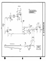
SCHEMATIC 4
SCHEMATIC 3
REVERB, PREAMPS AND EXPRESSION PEDAL
Audio signal from the String Preamps is applied to the Reverb
circuitry and to the String Preamp Emitter Follower Q52.
Signal output from the Reverb circuitry and Emitter Follow
er are mixed and amplified by the Reverb Mixer Q55. Signal
is then applied via the Volume Photocell P1 to the Main Pre
amps Q56 & Q57.
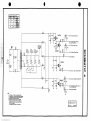
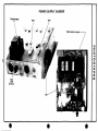
POWER SUPPLY
Positive and negative DC supply voltages are produced using
Transformer T1, Diodes D26-D31 and several [esistors and
filter capacitors. These DC voltages are supplied to the var
ious circuits of the organ.Zener Diodes Z1-Z3 and Regulator
Transistors Q60-Q63 are used as voltage regulators for
several voltage lines.
A 1/2 amp Slo/Blo fuse is also included in the Power
Q51 REVERB DRIVER
Supply circuit ahead of Power Transformer T1, to prevent
The audio output signal from the String Preamps Q48 & Q49
serious component damage in the event of a short circuit.
ADJUSTMENTS
VR5 TOUCH VIBRATO DELAY ADJUSTMENT
lator output, C for example. Turn on the Ensemble push
This adjustment is factory-set for maximum vibrato .8 sec
button with the High or Low pushbutton on. It is suggested
onds after key is pressed. Minimum vibrato should begin
a tuning fork for a certain note be used, C for example,
while holding down any C key on the keyboard. Adjust the
tuning coil with a non-metalic screw driver until the proper
pitch or frequency is acquired. When this note is properly
approximately .3 seconds after key is pressed.
VR1 TOS GLIDE ADJUSTMENT
The TOS Glide Adjustment regulates the amount the TOS is
de-tuned when the Glide Switch is pressed. To adjust for
proper de-tuning, ground out any Channel 2 Master Oscil
lator output, C for example, and turn on the Ensemble
Switch with either the High or Low pushbutton on. Hold
down any C key on the keyboard and the Glide Switch.
Now, using the TOS Glide Adjustment tune the TOS and
Channel 1 to zero beat.
tuned, the TOS tuning is automatically locked in.
L2, L3 CHANNEL 1 & 2 TUNING ADJUSTMENTS
Tune TOS as described for LLHold a key down and ground
output of Channel 2 "C" Master Oscillator. Tune Channel 1
"C" Master Oscillator to zero beat with TOS. Then ground
output of Channel 2 "C" Master Oscillator. Tune Channel 2
"C" Master Oscillator to zero beat with TOS. Repeat this
L1 TOS TUNING ADJUSTMENT
process with each note.
This Adjustment is carefully set at the factory. Should tun
NOTE: Like the TOS, the Ensemble pushbutton and the
ing be necessary, ground out any Channel 1 & 2 Master Oscil
High or Low pushbutton must be on before tuning.
I—I
buss drivers!
"*| HIGH & LOW I
J
I
|
I
Control
BALANCE
|
|
C3-C6
j BUSS DRIVERS
The Nvimotr
Designation Refers
I
J
j- -
•
I
The Letter Designation Refers
To The P. C. Board Where The
Components Within The Block
Are Located tSee Chart Below).
To The Scherratic
Number vwhere The
Circuit Within The
Qj
C3-C6
1_
I HIGH & LOW I
Block Is Located
Uj
(InThe Exarrplt Abo.e, The Circuit
Components V'ould Be Found On The
I
__J
1
i Signal Flaw
KEYBOARlfl
|_ CONTROL
I
I
|J<EYSW]TCHES_|
o
TOUCH
Touch Vibrato & Glide Board & The
Circuit Drawing Would 8t Found On
VIBRATO
I
KOEJIS
I
j_ CONTROL
I
Scherratic 1).
j
*1Tb-i
LTIf»M
ANIMATION
DRIVER
CD
'
.—,—i
O
O
j
I
!
^
|
GLIDE
■
SWITCH
T
TOUCH
VIBRATO
I
LSWITCHERSJ
-»| ANIMATION j
OSCILLATORS
1
'
'
TIC
CHANNEL?1
MASTER
OSCILLATORS
r-J-b£,
!
GlIDE
j
CHANNEL 1
MASTER
LJE_
CHANNEL 2
STRING
DIVIDERS
REVERB^
DRIVER
STRING "
CHANNEL 1
STRING
OSCILLATORS
REVERB
MIXER
KEYERS&
PREAMPS
DIVIDERS
VASTER L
VOL'JVE
CONTROL
VOLUME
PHOTOCaL
STRING I 3B
j_ SWITCH
PREAMP ^^
{
EMITTER
FOLLOWER
j
I
MASTER
OSCILLATOR
OCTAVE
SYNTHESIZERS
L2L
TOS
DIVIDERS
I.
-Qbj
ra i m
|
I
I
SUSTAIN
I.
REGULATOR |
SJSTAINER
CONTROL
I
,—Lm
MAIN
DL
PREAMPS
• To External
Amplifier
1. The boxed numbers represent a specific octane
frequency and do not refer to a keyboard octa;e.
ENSEMBLE
2. All resistors 1/2 Watt 10% un4ess otherwise specified.
3. All capacitors in microfarads unless otherwise specified.
4. All voltages measured to ground with a Simpson 260 VOM.
5. See Parts List for component part numbers.
6. All Pushbutton Switches are shown in OFF position.
7. For every woman who makes a fool out of a man,
there Is another woman who makes a man out of a fooL
8. .1 Capacitors Are Located On various Oi.ider
Voltage Lines. For Specific Locations See
String Symphonizer Board.
+ 18.5V
Gl5fe~Adj.
Tun
0)
o
X
m
O
1.8K
From Touch
__^
Example Channel 1
Vibrato Pushbutton^
D Master Oscillator
SeeDwg.2
(1 of 12 Channel 1 Master Oscillators)
From Touch
Vibrato Switchers
See Dwg. 2
Typical Outputs For Channel 1
1 of 6
Exarrpk Channel 2
C Vaster Oscillator
& Channel 2 C Dividers
(1 of 12 Channel 2 Master Oscillators I
GLIDE TONE GENERATORS.
ANIMATION & DIVIDERS
Dwg. No. 1
Model CSS
SCHEMATIC
i
SCHEMATIC
2
!
r-»
to Attitrai*!
Hqti *«itth Conttct
Iypkji Mvmq lir«
•
11
L
8«
Fraoi IN ^trtnq * 101 C«wr«tart.
lO.ltM VldMAlO
? M rtMtturt I 2 «Mtl l» •uitro itfWM* l»Ktlicd
I AH kMtitofi ••> mtcrotor«J» unWtt « trwu KiritfM.
« Ad M>0t(|N mMtuiMl to |found «0i • SlmpMn All VQV.
V Set
rt
4 *tt
n«ti But ttttto (ram «t»out
' loAntiMtlan
C
Otclltotort QUIM
) OM
c
C
OtcnWartQtOSJI
» ToAnlawtton
O*cm«tonQ|4?
)y»
Safe* I
J-1
•
2
REVERB
PREAMPS
NOTES
L
All resistors are 1/2 watt unless otherwise specified.
2. All capacibrs are in microfarads unless otherwise specified.
3.
All voltages are measured to ground with a Simpson 260 VOM.
4. See Parts List for component part numbers.
5. ♦ Denotes factory-tailored component
6. Happiness is like a kiss: you must share it to have it
o
X
m
+11 „ To External
"•l"^ Amplifier
O
CO
REVERB. PREAMPS &
EXPRESSION PEDAL
Owg. No. 3
Model CSS
18V To Animation Control & Driver
♦ 18.5 V To Touch Vibrato. Glide Keyers.
High. Low, & Reverb Drivers
♦ 13.5V To Re.erb &Main Preomps
+ 15.5V To Collector & String Preamps
CO
o
•18.5V To Glide Keyers
m
•13.5V To T.O.S.. Sustain. & Volume Photocell
♦13V To Channel 1 Oscillators & Ensemble Switch
+13V To String Dividers. Sustainer Control. &
T. 0. S. Via Ensemble Switch
♦ 13 V To Channel 2 Oscillators
NOTES
All resistors are 1/2 watt unless otherwise specified.
All capacitors are in microfarads unless otherwise specified.
All voltages measured to ground with a Simpson 260 VOM.
See parts list for component part numbers.
6.
irs eosler to break good resolutions than bad habits.
Components shown to tht right of plu^ & sockets are
J
All pushbutton switches shown in the off position.
located thruout tht organ refer to Component Location
Chart for their location.
POWER
Dwg. Na 4
SUPPLY
Model CSS
O
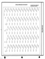
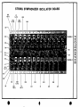
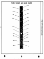
STRING SYMPHONIZER KEYING BOARD
For additional Callouts, see Photograph of
String Symphonizer Keying Board.
64. 6j,
0
Ox
O
S
38
(D,
f
0 |l
Q I
6a
©a
S
I
6a ©a ©a
)
J
t
©
ij)
QlJ
©
© |!| .©
©r1! , ©
O
39
0,
40
(D,
U f
41
©.
t
42
43
O.
t
O
rii
4
ljJ
I
©id
45
(Di
t
48
46
O±
(D
m
4
uJ
49
CD
foul r^n DEI GO Ron r«n ncn non nn doh nm DD GO DO 110 00 m m rm nn nn qo nn nn nn go on 00 nn 00
(0
oa do oa oa oa ce: od m qd gd go go do go od ced did od
CM
<
o
nn r*n rm r?n go rrn nn m nn ron nn rm do nn nn nn rm nn nn nn nn nn nn nn rm nn go rm nn
DO OO OD OO DO OD OD UH GO OD DD GO DO DD DO CiD GO OD GO GO OD GD DO OH QO OH HID DO DO CO 1~H
9MA1*
30010
SS3
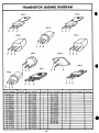
TRANSISTOR BASING DIAGRAM
FIG. B
FIG. A
FIG.C
FIG. E
FIG. D
C
B
FIG. F
FIG.K
14
i
STRING SYMPHONIZER OSCILLATOR BOARD
Q19
IC1-
IC2
CHANNEL 1
O
O
3D
>
■o
CO
Q10
Q12
Q23
1of 12
Q17
Q15
Q13
Q11
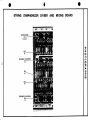
#
STRING
SYMPHONIZER
DIVIDER
AND
MIXING
BOARD
TOS DIVIDERS
IC3
(1of 12)
X
o
CHANNEL 1 DIVIDERS
IC4
12
H
O
o
3D
CHANNEL 2 DIVIDERS
IC5
12
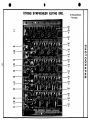
STRING SYMPHONIZER KEYING BRD.
See String Symphonizer
Keying Chart
CO
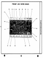
Q47
PREAMP
D15
D16
R2
Q55
AND
054
REVERB
Q52
BOARD
Q51
L6
D17,
Q27
037-
Q25
R1
C13
m
057
Q56
Q53
C12
m
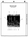
POWER SUPPLY BOARD
(Located in Power Supply Chassis)
Q62
o
H
Q61
D30
D27 D28
D29
D26
D31
Q60
o
o
POWER SUPPLY CHASSIS
TRANSFORMER
T1
P&S2
P&S1
POWER SUPPLY BOARD
o
a
3D
>
FUSE
.5 AMP
SLO/BLO
X
CO
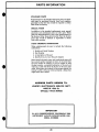
PARTS INFORMATION
STANDARD PARTS
Replacements for all standard electronic parts and hard
ware may be purchased directly from local suppliers
generally in less time than would be required to obtain
them from the factory.
SPECIAL PARTS
In addition to the standard replacement parts, special
electronic and mechanical parts are also used. These
parts are manufactured by and to the specifications of
the factory. Order these parts directly from the factory
since they would be difficult or impossible to obtain
from other sources.
PARTS ORDERING INFORMATION
When ordering parts be sure to include the following
information:
1. Model and Serial Number
2. Part Number
3. A description of the part
4. Specify how you want the part shipped.
Most special electronic parts and mechanical parts will
have a part number stamped on them. In the event that
the part number is missing, or you are unable to read
the part number, a complete description of the part and
where it is used will allow the factory to fill your parts
order. When parts are ordered in the proper manner the
factory is able to fill your orders promptly—delays that
might result are avoided.
ADDRESS PARTS ORDERS TO:
LOWREY ELECTRONICS SERVICE DEPT.
4400 W. 45th St.
Chicago, Illinois 60632
IMPORTANT
IN ANY CORRESPONDENCE CONCERNING THIS
INSTRUMENT ALWAYS INCLUDE MODEL AND
SERIAL NUMBERS
23
PARTS LIST
TABLE OF CONTENTS
CONSOLE ASSEMBLY
25
CONTROL PANEL ASSEMBLY
25
POWER SUPPLY BOARD ASSEMBLY
25
POWER SUPPLY CHASSIS ASSEMBLY
25
PREAMP & REVERB BOARD ASSEMBLY
25
STRING SYMPHONIZER DIVIDER & MIXING BOARD ASSEMBLY
26
STRING SYMPHONIZER KEYING BOARD ASSEMBLY
26
STRING SYMPHONIZER OSCILLATOR BOARD ASSEMBLY
26
SWELL PEDAL ASSEMBLY
26
TOUCH VIBRATO & GLIDE BOARD ASSEMBLY
27
THE PARTS LIST CONTAINS THE FOLLOWING INFORMATION:
1. Name of Part
2. Value, Tolerance and Code (When Important)
3. Brief description
4. Where the part is found (assembly, printed circuit board, etc.)
5. Schematic Reference Number
6. PART NUMBER - USE IT!
This parts list includes all standard stock replacement parts. No attempt has been made to
include every nut, bolt and screw. If the necessity for a non-listed part arises, please write
describing the parts location and function as well as model and serial number of the unit.
24
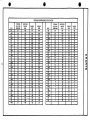
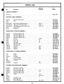
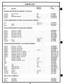
PARTS LIST
Part
Description
Schematic
Part
Reference
Number
PREAMP & REVERB BOARD ASSEMBLY (Continued)
Transistor
Emitter Follower
Q52
991-008393
Transistor
Driver
Q7
991-015587
Transistor
PNP Sustain Regulator
Q37
991-020425-3
Q25,27
991-020426-3
Transistor
STRING SYMPHONIZER DIVIDER & MIXING BOARD ASSEMBLY
Diode
IC
Divider
Socket
14-Pin
D20,21,22
919-004799
IC3, 4, 5
991-013182-1
906-018905
STRING SYMPHONIZER KEYING BOARD ASSEMLBY
Capacitor
Electrolytic 1 UF 20V
945-008895-11
Capacitor
Electrolytic 2 UF 25V
945-015619
Capacitor
Electrolytic 4 UF 20V
945-019366
Capacitor
Electrolytic 6 UF 20V
945-019366-1
Capacitor
Electrolytic 8 UF 15V
945-019366-2
Capacitor
Electrolytic 10 UF 15V
945-019366-3
D18, 19,23
919-004799
Transistor
Diode
Keyer
Q38-42
991-008393
Transistor
Preamp
Q43-49
991-018238
STRING SYMPHONIZER OSCILLATOR BOARD ASSEMBLY
Capacitor
Electrolytic 1 UF 20V
945-008895-11
Capacitor
Electrolytic 1.4 UF 15V
945-008895-4
Capacitor
Electrolytic 2 UF 20V NP
Capacitor
Electrolytic 100 UF 20V
Capacitor
Polystyrene .01 UF +2-1/2% 33V
946-013181-103
Capacitor
Polystyrene .012 UF -2-1/2% 33V
946-013181-123
Capacitor
Polystyrene .015 UF +2-1/2% 33V
946-013181-153
Capacitor
Polystyrene .022 UF +2-1/2% 33V
946-013181-223
Capacitor
Polystyrene 560 PF 2-1/2% 33V
Coil
Oscillator Tuning Adj
L2,3
952-009978-2
Coil
Oscillator Tuning Adj
L2# 3
952-009978-3
Coil
Oscillator Tuning Adj. 140 UH
L1
952-018874
D2, 10, 11
919-004799
945-008895-32
C14, 15
945-020064
946-013181-561
Diode
Diode
D3
919-010873
IC
TOS
IC2
991-018813-1
IC
TOS
IC1
991-018813-2
Resistor
WW .47 Ohm 2W
R3,4
924-015325-8
Resistor
WW 220 Ohm 2W
Socket
14-Pin
Transistor
Oscillator
Q4,8-23
991-008393
Transistor
Buffer
Q5
991-016727
Transistor
Wave Shaper
Q6
991-015587
924-010471-221
906-018905
SWELL PEDAL ASSEMBLY
997-015722
959-008052
851-352220
26
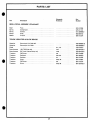
PARTS LIST
Part
Schematic
Reference
Description
Part
Number
SWELL PEDAL ASSEMBLY (Continued)
Shaft
Pivot
Spring
Compression
975-011747
Spring
Contact
917-009989-2
Switch
Glide
960-008102
Washer
Friction
904-012674
974-012359
TOUCH VIBRATOR & GLIDE BOARD
Capacitor
Electrolytic 2 UF 20V NP
Capacitor
Electrolytic 3 UF 50V
945-008895-32
945-008895-6
Diode
D1,4-9
919-010873
925-004349-3
Potentiometer
10K TOS Glide Adj
VR1
Potentiometer
5K Touch Vibrato Delay Adj
VR5
925-004349-5
Transistor
PNP Keyer
Q2
991-010098
Transistor
Oscillator
Q31-36
991-008393
Transistor
Switcher
Q1
991-013544
Transistor
Keyer
Q29,30
991-015587
Transistor
PNP Keyer
Q3
991-015614
Transistor
Driver
Q26,28
991-020426-3
27