1
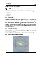
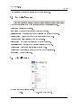
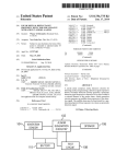
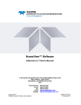
SWFView User's Manual 2.0
Prepared by
Aerodyne Research, Inc.
45 Manning Road
Billerica, MA 01821
10 February 2011
SWFView 1.99.8
ii
c 2006, 2010 Fred Bacon
Copyright Permission is granted to copy, distribute and/or modify this document under the terms of the
GNU Free Documentation License (GFDL), Version 1.1 or any later version published by the
Free Software Foundation with no Invariant Sections, no Front-Cover Texts, and no Back-Cover
Texts. You can nd a copy of the GFDL at this link or in the le COPYING-DOCS distributed
with this manual.
DOCUMENT AND MODIFIED VERSIONS OF THE DOCUMENT ARE PROVIDED UNDER THE TERMS OF THE GNU FREE DOCUMENTATION LICENSE WITH THE FURTHER UNDERSTANDING THAT:
1. DOCUMENT IS PROVIDED ON AN "AS IS" BASIS, WITHOUT WARRANTY OF
ANY KIND, EITHER EXPRESSED OR IMPLIED, INCLUDING, WITHOUT LIMITATION, WARRANTIES THAT THE DOCUMENT OR MODIFIED VERSION OF THE
DOCUMENT IS FREE OF DEFECTS MERCHANTABLE, FIT FOR A PARTICULAR PURPOSE OR NON-INFRINGING. THE ENTIRE RISK AS TO THE QUALITY, ACCURACY, AND PERFORMANCE OF THE DOCUMENT OR MODIFIED
VERSION OF THE DOCUMENT IS WITH YOU. SHOULD ANY DOCUMENT OR
MODIFIED VERSION PROVE DEFECTIVE IN ANY RESPECT, YOU (NOT THE
INITIAL WRITER, AUTHOR OR ANY CONTRIBUTOR) ASSUME THE COST OF
ANY NECESSARY SERVICING, REPAIR OR CORRECTION. THIS DISCLAIMER
OF WARRANTY CONSTITUTES AN ESSENTIAL PART OF THIS LICENSE. NO
USE OF ANY DOCUMENT OR MODIFIED VERSION OF THE DOCUMENT IS AUTHORIZED HEREUNDER EXCEPT UNDER THIS DISCLAIMER; AND
2. UNDER NO CIRCUMSTANCES AND UNDER NO LEGAL THEORY, WHETHER IN
TORT (INCLUDING NEGLIGENCE), CONTRACT, OR OTHERWISE, SHALL THE
AUTHOR, INITIAL WRITER, ANY CONTRIBUTOR, OR ANY DISTRIBUTOR OF
THE DOCUMENT OR MODIFIED VERSION OF THE DOCUMENT, OR ANY SUPPLIER OF ANY OF SUCH PARTIES, BE LIABLE TO ANY PERSON FOR ANY DIRECT, INDIRECT, SPECIAL, INCIDENTAL, OR CONSEQUENTIAL DAMAGES OF
ANY CHARACTER INCLUDING, WITHOUT LIMITATION, DAMAGES FOR LOSS
OF GOODWILL, WORK STOPPAGE, COMPUTER FAILURE OR MALFUNCTION,
OR ANY AND ALL OTHER DAMAGES OR LOSSES ARISING OUT OF OR RELATING TO USE OF THE DOCUMENT AND MODIFIED VERSIONS OF THE DOCUMENT, EVEN IF SUCH PARTY SHALL HAVE BEEN INFORMED OF THE POSSIBILITY OF SUCH DAMAGES.
SWFView 1.99.8
iii
COLLABORATORS
TITLE
:
SWFView 1.99.8
ACTION
NAME
DATE
WRITTEN BY
Fred Bacon
December 2006
SIGNATURE
REVISION HISTORY
NUMBER
DATE
SWFView
May 2010
Manual: Version
Research, Inc.
December 2006
Manual: Version
SWFView
1.0
Fred Bacon
Aerodyne
1.0.1
Manual: Version
Fred Bacon
Aerodyne
2.0
SWFView
DESCRIPTION
Research, Inc.
July 2006
Fred Bacon
Aerodyne
Research, Inc.
NAME
SWFView 1.99.8
iv
Contents
1
2
Introduction
1
1.1 About SWFView . . . . . . . . . . . . . . . . . . . . . . . . . . . . . . . . . . . . . .
1
1.2 A Short History of SWFView . . . . . . . . . . . . . . . . . . . . . . . . . . . . . . .
1
Main Window
3
2.1 Geometry Browser . . . . . . . . . . . . . . . . . . . . . . . . . . . . . . . . . . . . .
4
2.1.1 Mouse Behavior . . . . . . . . . . . . . . . . . . . . . . . . . . . . . . . . . .
4
2.1.1.1
Single Clicking . . . . . . . . . . . . . . . . . . . . . . . . . . . . . .
4
2.1.1.2
Double Clicking . . . . . . . . . . . . . . . . . . . . . . . . . . . . .
4
2.2 Display Interactions . . . . . . . . . . . . . . . . . . . . . . . . . . . . . . . . . . . .
5
2.2.1 Mouse actions . . . . . . . . . . . . . . . . . . . . . . . . . . . . . . . . . . . .
5
2.2.2 Keyboard Commands . . . . . . . . . . . . . . . . . . . . . . . . . . . . . . .
5
2.2.3 Body Centered Coordinate Rotations . . . . . . . . . . . . . . . . . . . . . .
5
2.3 SWFView's Menus . . . . . . . . . . . . . . . . . . . . . . . . . . . . . . . . . . . . .
6
2.4 The File Menu . . . . . . . . . . . . . . . . . . . . . . . . . . . . . . . . . . . . . . .
6
2.5 The Edit Menu . . . . . . . . . . . . . . . . . . . . . . . . . . . . . . . . . . . . . . .
7
2.6 The Selection Menu . . . . . . . . . . . . . . . . . . . . . . . . . . . . . . . . . . . .
8
2.7 The Display Menu . . . . . . . . . . . . . . . . . . . . . . . . . . . . . . . . . . . . .
9
2.7.1 Rendering Mode . . . . . . . . . . . . . . . . . . . . . . . . . . . . . . . . . .
9
2.7.2 Background Color . . . . . . . . . . . . . . . . . . . . . . . . . . . . . . . . .
10
2.7.3 Display Options . . . . . . . . . . . . . . . . . . . . . . . . . . . . . . . . . .
10
2.8 The Camera Menu . . . . . . . . . . . . . . . . . . . . . . . . . . . . . . . . . . . . .
12
2.9 The Lights Menu . . . . . . . . . . . . . . . . . . . . . . . . . . . . . . . . . . . . . .
13
2.10 The Materials Menu . . . . . . . . . . . . . . . . . . . . . . . . . . . . . . . . . . . .
14
2.10.1 Specifying Materials for Display . . . . . . . . . . . . . . . . . . . . . . . . .
14
2.10.2 Paint Mode . . . . . . . . . . . . . . . . . . . . . . . . . . . . . . . . . . . . .
14
SWFView 1.99.8
v
2.11
2.12
2.13
2.14
2.15
2.16
The Model Menu . . . . . . .
The Tools Menu . . . . . . .
The Help Menu . . . . . . . .
SWFView's Tool Bars . . . .
The File Tool Bar . . . . . .
Edit Tools . . . . . . . . . . .
2.16.1 Facet Selection Mode
2.17 The Camera Tool Bar . . . .
2.18 The Status Bar . . . . . . . .
3
.
.
.
.
.
.
.
.
.
.
.
.
.
.
.
.
.
.
.
.
.
.
.
.
.
.
.
.
.
.
.
.
.
.
.
.
.
.
.
.
.
.
.
.
.
.
.
.
.
.
.
.
.
.
.
.
.
.
.
.
.
.
.
.
.
.
.
.
.
.
.
.
.
.
.
.
.
.
.
.
.
.
.
.
.
.
.
.
.
.
.
.
.
.
.
.
.
.
.
.
.
.
.
.
.
.
.
.
.
.
.
.
.
.
.
.
.
.
.
.
.
.
.
.
.
.
.
.
.
.
.
.
.
.
.
.
.
.
.
.
.
.
.
.
.
.
.
.
.
.
.
.
.
.
.
.
.
.
.
.
.
.
.
.
.
.
.
.
.
.
.
.
.
.
.
.
.
.
.
.
.
.
.
.
.
.
.
.
.
.
.
.
.
.
.
.
.
.
.
.
.
.
.
.
.
.
.
.
.
.
.
.
.
.
.
.
.
.
.
.
.
.
.
.
.
.
.
.
.
.
.
.
.
.
.
.
.
.
.
.
.
.
.
.
.
.
.
.
.
.
.
.
.
.
.
.
.
.
.
.
.
.
.
.
.
.
.
.
.
.
Common Dialog Boxes
3.1
3.2
3.3
3.4
3.5
3.6
3.7
3.8
3.9
3.10
3.11
3.12
3.13
3.14
3.15
3.16
4
.
.
.
.
.
.
.
.
.
Part Key Dialog . . . . . .
Aerodynamic Shape Dialog
Patch Key Dialog . . . . . .
Translate Object Dialog . .
Rotate Object Dialog . . . .
Scale Object Dialog . . . .
Materials Editor Dialog . .
3.7.1 Dialog Box Layout .
3.7.2 Materials List . . . .
3.7.3 Material Properties .
3.7.4 Bugs . . . . . . . . .
Comment Editor Dialog . .
Plume Table Editor Dialog
Wireframe Info Dialog . . .
Exporting OBJ Files . . . .
Aim Point Dialog . . . . . .
Camera Position Dialog . .
Light Editor . . . . . . . . .
Open File Dialog . . . . . .
SWF Library Error Dialog .
23
.
.
.
.
.
.
.
.
.
.
.
.
.
.
.
.
.
.
.
.
.
.
.
.
.
.
.
.
.
.
.
.
.
.
.
.
.
.
.
.
.
.
.
.
.
.
.
.
.
.
.
.
.
.
.
.
.
.
.
.
.
.
.
.
.
.
.
.
.
.
.
.
.
.
.
.
.
.
.
.
.
.
.
.
.
.
.
.
.
.
.
.
.
.
.
.
.
.
.
.
.
.
.
.
.
.
.
.
.
.
.
.
.
.
.
.
.
.
.
.
.
.
.
.
.
.
.
.
.
.
.
.
.
.
.
.
.
.
.
.
.
.
.
.
.
.
.
.
.
.
.
.
.
.
.
.
.
.
.
.
.
.
.
.
.
.
.
.
.
.
.
.
.
.
.
.
.
.
.
.
.
.
.
.
.
.
.
.
.
.
.
.
.
.
.
.
.
.
.
.
.
.
.
.
.
.
.
.
.
.
.
.
.
.
.
.
.
.
.
.
.
.
.
.
.
.
.
.
.
.
.
.
.
.
.
.
.
.
.
.
.
.
.
.
.
.
.
.
.
.
.
.
.
.
.
.
.
.
.
.
.
.
.
.
.
.
.
.
.
.
.
.
.
.
.
.
.
.
.
.
.
.
.
.
.
.
.
.
.
.
.
.
.
.
.
.
.
.
.
.
.
.
.
.
.
.
.
.
.
.
.
.
.
.
.
.
.
.
.
.
.
.
.
.
.
.
.
.
.
.
.
.
.
.
.
.
.
.
.
.
.
.
.
.
.
.
.
.
.
.
.
.
.
.
.
.
.
.
.
.
.
.
.
.
.
.
.
.
.
.
.
.
.
.
.
.
.
.
.
.
.
.
.
.
.
.
.
.
.
.
.
.
.
.
.
.
.
.
.
.
.
.
.
.
.
.
.
.
.
.
.
.
.
.
.
.
.
.
.
.
.
.
.
.
.
.
.
.
.
.
.
.
.
.
.
.
.
.
.
.
.
.
.
.
.
.
.
.
.
.
.
.
.
.
.
.
.
.
.
.
.
.
.
.
.
.
.
.
.
.
.
.
.
.
.
.
.
.
.
.
.
.
.
.
.
.
.
.
.
.
.
.
.
.
.
.
.
.
.
.
.
.
.
.
.
.
.
.
.
.
.
.
.
.
.
.
.
.
.
.
.
.
.
.
.
.
.
.
.
.
.
.
.
.
.
.
.
.
.
.
.
.
.
.
.
.
.
.
.
.
.
.
.
.
.
.
.
.
.
.
.
.
.
.
.
.
.
.
.
.
.
.
.
.
.
.
.
.
.
.
.
.
.
.
.
.
.
.
.
.
.
.
.
.
.
.
.
.
.
.
.
.
.
.
.
.
.
.
.
.
.
.
.
.
.
.
.
.
.
.
.
.
.
.
.
.
.
.
.
.
.
.
.
.
.
.
.
.
.
.
File Formats
4.1
4.2
4.3
4.4
4.5
4.6
17
18
18
19
19
20
20
21
22
Material File Formats . . . . .
Materials File Format: .mtx .
Materials Denition Format . .
Auxiliary Geometry Formats .
Part/Patch Order File Format
VPSculpt Region File Format .
23
24
25
27
28
28
29
29
29
30
30
31
31
32
33
33
34
35
36
37
39
.
.
.
.
.
.
.
.
.
.
.
.
.
.
.
.
.
.
.
.
.
.
.
.
.
.
.
.
.
.
.
.
.
.
.
.
.
.
.
.
.
.
.
.
.
.
.
.
.
.
.
.
.
.
.
.
.
.
.
.
.
.
.
.
.
.
.
.
.
.
.
.
.
.
.
.
.
.
.
.
.
.
.
.
.
.
.
.
.
.
.
.
.
.
.
.
.
.
.
.
.
.
.
.
.
.
.
.
.
.
.
.
.
.
.
.
.
.
.
.
.
.
.
.
.
.
.
.
.
.
.
.
.
.
.
.
.
.
.
.
.
.
.
.
.
.
.
.
.
.
.
.
.
.
.
.
.
.
.
.
.
.
.
.
.
.
.
.
.
.
.
.
.
.
.
.
.
.
.
.
39
39
40
41
42
43
SWFView 1.99.8
vi
5
6
How Do I...
44
5.1 How do I translate a model into SPIRITS wireframe format? . . . . . . . . . . . . .
44
5.2 How do I correct inverted facets? . . . . . . . . . . . . . . . . . . . . . . . . . . . . .
45
5.3 How do I combine multiple patches into one? . . . . . . . . . . . . . . . . . . . . . .
45
5.4 How do I split a patch into multiple patches? . . . . . . . . . . . . . . . . . . . . . .
46
5.5 How do I move a patch from one part to another? . . . . . . . . . . . . . . . . . . .
46
5.6 How do I rename a patch? . . . . . . . . . . . . . . . . . . . . . . . . . . . . . . . . .
47
5.7 How do I remove a patch or part from a model? . . . . . . . . . . . . . . . . . . . . .
47
5.8 How do I extract a part or patch to a new model? . . . . . . . . . . . . . . . . . . .
47
Acknowledgements
49
6.1 Third-party Software . . . . . . . . . . . . . . . . . . . . . . . . . . . . . . . . . . . .
49
6.2 Special Thanks . . . . . . . . . . . . . . . . . . . . . . . . . . . . . . . . . . . . . . .
49
SWFView 1.99.8
1 / 49
Chapter 1
Introduction
1.1 About SWFView
SWFView is a geometry browser and translator for 3D models used with SPIRITS. The code was
developed to allow SPIRITS and PMO users to visualize models, translate foreign le formats into
the SPIRITS wireframe format and set part and patch attributes in an easy to use graphical user
interface.
SWFView is unsupported software because there is no nancial support for working on the code.
Modications and upgrades are dependent on ongoing contracts and the whim of the developers, so
use it at your own risk. However, since the software is used on a daily basis at Aerodyne, the code
is fairly stable and productive. A low volume mailing list for SWFView is available at Aerodyne.
To subscribe, go to https://mailman.aerodyne.com/mailman/listinfo/swfview and ll out the subscription form. Notices of major new releases are announced on this mailing list. Any discussions
concerning the software can be made on this mailing list, or sent directly to [email protected].
While SWFView is open source, the code is the property of Aerodyne Research, Inc. of Billerica,
Massachussets except those third party libraries developed by others and noted in the source code
distribution.
1.2 A Short History of SWFView
I did not set out to write a geometry editor for SPIRITS wireframe models. Instead, SWFView grew
through accretion. This chaotic development process is responsible for the sometimes odd feature
set present in the code.
The oldest components in SWFView are the functions for writing wireframe les. These were written
under a contract for the Navy when I needed to create a complex geometric model. I wrote a small
command line utility that allowed me to build my model one facet at a time. The code was simple,
fragile and useful only to me at the time.
The next phase of development came when I decided to play with a software library for displaying
3D models in a window. It was just for my own curiosity. To display the models, I had to write a
le parser that would load a SPIRITS wireframe model into the data structures I had previously
created for writing my earlier model. Showing o the crude viewer to some of my coworkers, I was
SWFView 1.99.8
2 / 49
quickly barraged by requests to port the viewer from Linux to Windows. Suddenly, I had to nd
a way to create a real user interface that I could write for both Windows and Linux. The fastest,
cheapest route was by using the Qt library from TrollTech.
Over the succeeding years, that rst crude viewer acquired new features as a succession of contracts
found uses for the code. Within Aerodyne, the code was used by everyone working with SPIRITS,
and everyone needed changes made to accomodate their current projects. With each modication,
SWFView became more useful and indispensible. We needed geometry models translated from one
format after another. We began passing copies to our customers so that they could visualize the
work we were doing for them. We needed some way to create gures to put in reports. Feature after
feature was added, sometimes in the heat of the moment, with never a thought for the design of the
software.
Throughout the development of SWFView, the original design of the data structures from that rst
command line geometry editor have remained. True, they have acquired new elds, expanding as
required by each new feature, but the core design has remained. Those original design choices have
hampered the code with a number of performance bottle necks. One day, I hope to replace those
low level routines and data structures with a new design, but until funding arrives from somewhere
(or I simply grow tired of the bottlenecks and tackle the problem in my spare time), SWFView is
going to have performance problems for models with more than 20,000 facets.
That's the current state of the code.
SWFView 1.99.8
3 / 49
Chapter 2
Main Window
SWFView's main window.
The main window of SWFView consists of the Menu Bar, the Toolbar, the Geometry Browser, the
Display Window, and the Status Bar.
On the Macintosh, the menu bar will be at the top of the screen rather than in the window itself.
This is in keeping with the Apple's Human Interface Guidelines.
SWFView 1.99.8
4 / 49
2.1 Geometry Browser
SWFView's geometry browser window displays a heirarchical list of the parts and patches in the
open model.
The Geometry Browser, located in the left hand pane of the main window, is a tree list structure
showing the heirarchical part-patch structure of the wireframe model. Since this application is
primarily intended for working with SPIRITS wireframe les, geometry models imported from other
le formats will be restructured automatically into this format.
2.1.1
Mouse Behavior
2.1.1.1
Single Clicking
Clicking on a part or patch name in the Geometry Browser window will highlight that component
within the Display Window. You may shift-click in the browser to select a range of parts and patches.
By control-clicking, you can select noncontiguous items in the browser.
To clear your selection, click in an empty region of the Geometry Browser window or select Clear
Selection from the Edit menu.
2.1.1.2
Double Clicking
Double clicking on a part or patch name in the Geometry Browser window will open the appropriate
dialog box for editing the SPIRITS keys for the part or patch.
SWFView 1.99.8
5 / 49
See also: Part Key Dialog, Patch Key Dialog
2.2 Display Interactions
It is possible for the user to adjust the display perspective via three methods in SWFView.
• The Mouse
• The Keyboard
• The Menus
2.2.1
Mouse actions
Left clicking and draggin in the display window will rotate the wireframe. If you imagine that the
object is inside a glass sphere which is free to rotate, then the behavior of dragging the mouse is like
similar to what you would expect if you were use your hand to rotate the sphere via friction.
Right clicking on the display window allows you to drag the object from left to right and up and
down within the frame with the mouse movement.
Clicking the middle button (or pressing Ctrl key in conjunction with the Left mouse button) allows
you to zoom in and out on the object. Moving the mouse vertically zooms in on the object. Moving
the mouse down zooms out.
2.2.2
Keyboard Commands
Pressing the R, P or Y keys (when the viewing area is active) will roll, pitch or yaw the object in
its body centered coordinate system.
Pressing the J, K and L keys will rotate about the X, Y and Z screen coordinate system.
2.2.3
Body Centered Coordinate Rotations
SWFView 1.99.8
6 / 49
Use the Shift key to reverse the direction of any of these commands.
2.3 SWFView's Menus
Most of the functionality of SWFView is accessed through the applications menus.
File Menu
Edit Menu
File oriented operations.
Operations which aect the content of the model.
Operations which aect the selection of model sub components.
Selection Menu
Display Menu
Options which aect the on screen display of the model.
Camera Menu
Select collection of xed view directions.
Lights Menu
Commands which allows you to control the lighting.
Materials Menu
Model Menu
Tools Menu
Help Menu
Access and apply material denitions to the model.
Perform geometric transformations on model.
Functionality to enable you to modify the model's structure.
Access to online help.
2.4 The File Menu
The File menu has the following options.
Ctrl-N
New - Opens a new window.
SWFView 1.99.8
7 / 49
Ctrl-O
Ctrl-S
Ctrl-W
Ctrl-Q
2.5 The Edit Menu
Open - Opens a new model. If a model is
open in the current window, a new
window will be opened automatically. If
no model is currently opened, then the
current window will be used.
Save - Saves the current model to a
SPIRITS type wireframe le.
Save As... - Allows you to save the open
model in one of the supported formats.
Print - Is not currently available.
Instead, you can save the model as a
postscript le or PNG image.
Close - Closes the current window. If no
other windows are open, then the
SWFView will exit.
Quit - Closes all open windows and exits
the application.
SWFView 1.99.8
8 / 49
2.6 The Selection Menu
• Select All - Selects and highlights all parts and patches in the model.
• Clear Selection - Deselects and unhighlights any parts or patches that are currently selected.
• Invert Selection - Inverts the selection of parts and patches.
• Select by Key - Opens a dialog box which allows you to select parts and patches based on a
specied key's value.
• Hide Selection - Hides any selected parts or patches. If a part is hidden, then all of its patches
are hidden by denition whether the patches are selected or not.
• Show Selected - Any selected part or patch that is hidden will be displayed.
• Merge Selected - If multiple patches are selected, then they will be merged into a single patch.
There is no undo available for this action.
• Create New Part... - Creates a new part in the model and opens a dialog box so that you can
specify the name and SPIRITS part keys. Useful when you want to repartition a model imported
from a dierent le format.
• Repaint All Elements... - Gives the user the option to set the reection key for all parts and
patches to a specied value.
• Material Coverage... - Builds a comma separated value list of areas for each material on every
part. From the dialog box you can save the text to a le for import into a spreadsheet.
SWFView 1.99.8
9 / 49
2.7 The Display Menu
The Display menu is divided into three major sections. The top most section determines how the
model will be rendered in display window. The middle section is used to turn on various optional
display features. The bottom section allows the user to colorize the model according to the selected
part/patch key. We will go through these items one at a time to discuss their use.
2.7.1
Rendering Mode
The top section species the rendering mode of the model in the display window. The options
are Facet, Wireframe, Both and Points. Only one rendering mode at a time can be selected. The
currently selected mode will have a checkmark displayed next to left of the mode's name.
Mode
Description
Facet
Each facet of the model is rendered as a
at plate with uniform shading.
Wireframe
Only the edges of the facets are rendered
on screen.
Both
The facets are rendered as at, uniformly
shaded plates with the edges highlighted
in red.
Example
SWFView 1.99.8
10 / 49
Points
2.7.2
The verticies dening the model are
rendered as a cloud of red points.
Background Color
• Set Background Color... - Allows the user to specify the background color for the display area.
• Default Background Color - Restores the background color of the display area to its default value.
2.7.3
Display Options
The middle portion of the Display menu comprises a set of individual display options that operate
in an ON/OFF mode. Each option may be toggled on and o by selecting the appropriate menu
item. When an option is on, a checkmark will be displayed to the left of the option's name.
The one exception to this statement is the rst option in this section. Toggling between the Perspective mode and Orthographic mode changes the name of the menu item. The normal operational
mode is Perspective. In this mode, the menu will display the option Orthographic. Selecting this
menu item will then select the display to an orthographic projection and the menu item becomesPerspective. Selecting the Perspective projection mode will return the display back to its original
projection. The dierence between the two projections can be seen in the following images.
Perspective
Orthographic
Toggling the Show Body Axes option will result in the display of a set of three compass dials in
each of the three coordinate planes. The origin of the display coordinate system is the center of the
bounding box containing the 3D model. It is not necessarily at the origin of the actual model as
represented in the on disk le.
Show Body Axes
SWFView 1.99.8
11 / 49
Toggling the Hide Facet Backs option turns o the rendering of facets when viewed from the back.
This option exists to aide the user in identifying inverted facets. The eect of enabling this option
can be seen in the following gures.
Show Facet Backs
Hide Facet Backs
The next two options, Show Facet Normals and Show Plume Vectors, turn on the display of facet
normals and the plume vectors dened in the wireframe model, if any. The rst option exists to help
identify inverted facets in the model. The second option exists to help the user identify mispositioned
plume vectors.
The eect of turning on these options can be seen in the following gures.
Show Facet Normals
Show Plume Vectors
SWFView 1.99.8
12 / 49
The normal operational mode of SWFView is to use a shading algorithm that results in a 3D eect.
By choosing the Flat Shading algorithm instead, you can produce a at, "cartoon" like rendering
algorithm that may be useful for producing illustrations.
Normal Shading
Flat Shading
2.8 The Camera Menu
The following xed view points are dened in SWFView. The corresponding name and keyboard
shortcuts for switching to these views are shown below.
SWFView 1.99.8
13 / 49
TopCtrl-T
BottomCtrl-B
FrontCtrl-F
BackCtrl-K
LeftCtrl-L
RightCtrl-R
ProjectionCtrl-P
2.9 The Lights Menu
SWFView 1.99.8
14 / 49
2.10 The Materials Menu
2.10.1
Specifying Materials for Display
• Edit Materials... - Opens a dialog box that allows you to create, edit and export material deni-
tions.
• Import Materials... - Import material denitions from a le.
• Export Materials... - Export material denitions to a le for later use.
2.10.2
Paint Mode
The second section of the Materials menu determines how the model is painted in the display. The
colors are determined by the Materials dened by the user. Materials can be imported from a le
or dened in the Materials Editor Dialog.
Colors are assigned to parts, patches, paint keys and color keys in order of their denition. When
the Paint by Part option is selected, the rst material dened is placed on the rst part. The second
dened is placed on the second part, etc.. The same is true for the other options.
The following images demonstrate how each choice aects the display of a model.
Uniform Paint
SWFView 1.99.8
15 / 49
By Part
By Patch
By Paint
SWFView 1.99.8
16 / 49
By Color Key
By Temperature
Key
By Facet Index
See also: Edit Material Dialog
SWFView 1.99.8
17 / 49
2.11 The Model Menu
The Model menu collects together functionality to let you perform geometric transformations on the
entire model. The allowed transformations are:
• Get Info... - Opens a dialog box which displays summary information about the geometric model.
• New Part - Creates a new SPIRITS type part in the model. Opens a dialog box which allows you
to edit the part keys and name.
• Translate - Performs an arbitrary translation of the model, thus moving the origin of coordinates.
• Rotate - Performs arbitrary rotations about the X (Roll), Y (Pitch) and Z (Yaw) axes.
• Scale - Scales the model in the X, Y and Z directions. Scale factor can be specied in either
wireframe units or in percent of current size.
• Set Wireframe Units - A model imported from another format, may not have had the model units
set correctly. This menu item allows you to dene the system of units in which the model is
expressed.
• Change Wireframe Units - At times it is advantageous to convert a model from one system of
units to another. This menu item opens a dialog which allows you to convert the model from one
system of units to another.
• Edit Comments... - Opens a simple text editor for adding or editing comments to a SPIRITS
wireframe le.
• Edit Plume Table... - Opens a dialog box where you can add, modify or delete plumes from the
model.
See alsoTranslate Object Dialog, Rotate Object Dialog and Scale Object Dialog references.
SWFView 1.99.8
18 / 49
2.12 The Tools Menu
2.13 The Help Menu
The Help menu provides online assistance to the user by allowing them to access the documentation
system.
About SWFView
About Qt
Help Browser
Show (Hide) Tooltips
What's This?
Opens a dialog giving the version number and
release date of this software.
Opens a dialog box giving information about the
Qt library version used in the software.
Opens this online help documentation system.
Provides a means for the user to turn popup
tooltips (balloon help) on or o. When enabled,
tooltips will provide a brief description of a user
interface element, when the mouse hovers over
the element.
Many user interface elements have additional
documentation available that can be accessed via
this option. Selecting this option and clicking on
an element of the user interface will display
additional documentation if it is available.
SWFView 1.99.8
19 / 49
2.14 SWFView's Tool Bars
SWFView contains a small number of toolbars which provide easy access to some of the more
important functions of the application.
• File Tools - Provides quick access to some of the important File menu items.
• Edit Tools -Provides quick access to functions for reorganizing the model.
• Camera Tools - Allows the user to switch between dierent view directions.
2.15 The File Tool Bar
Open - Click this button to open a new
le. You can also use Ctrl-O or select the
Open command from the File menu.
Save - Click this button to save the
current model to a le. This will always
save as wireframe le, which is not
necessarily the original le type. You can
also use Ctrl-S or select the Save
command from the File menu.
Print - Click on this button to print the
display window. You can also use Ctrl-P
or select the Print from the File menu.
Exit - Click this button to exit
SWFView. You can also use Ctrl-Q or
select the Exit command from the File
menu.
What's This? -Click this button to enter
What's this? mode. In this mode, the
cursor will change to an arrow with a
question mark. Clicking on a user
interface element will display popup help
for the element.
SWFView 1.99.8
20 / 49
2.16 Edit Tools
Normal Operational Mode
Facet Selection Mode
Merge Selected - Click on this button to merge any
selected patches into a single patch. Only patches are
merged by this operation. Any selected parts are ignored,
but selected patches within them will be merged. Patches
can be merged across parts.
Group Marked Facets - When in Facet Selection Mode ,
you can select (or mark) multiple facets in the display
window with the mouse. Clicking on this button will
group the marked facets into a new patch. They are
removed from their original patches. This operation is
irreversible and is only available when in Facet Selection
Mode.
Flip Facet Normals - When in Facet Selection Mode ,you
can select multiple facets in the display window with the
mouse. Clicking on this button will change the
orientation of the marked facets. This operation does not
change the facet indexing.
Info - Clicking on this button will open a dialog box that
contains information on the number of parts, patchs,
facets and dimensions of the model. You can also access
this dialog box by pressing Ctrl-I on the keyboard.
Light Facets - Click on this button to toggle between
Facet Selection Mode.
2.16.1
Facet Selection Mode
allows the user to toggle in and out of Facet Selection Mode. When
The Light Facets button
in facet selection mode, a facet will be highlighted in red when the mouse is over that facet. The
relative facet index (see the SPIRITS documentation) will be displayed in the statusbar.
You can select multiple facets by holding down the shift key and clicking on each facet with the left
mouse button. To deselect a facet, you need to shift-click on the facet a second time.
SWFView 1.99.8
21 / 49
2.17 The Camera Tool Bar
From top to bottom, the camera options specied in this tool bar are:
Top - Ctrl-T
Bottom - Ctrl-B
Front - Ctrl-F
Back - Ctrl-K
Left - Ctrl-L
Right - Ctrl-R
Projection - Ctrl-P
Aim Point - Set the sensor aim point in 3D space.
Camera - Open a dialog to set the camera position
relative to the target.
Allowing the mouse to hover over a button will display a tooltip giving the name of the view direction.
The view icons are based on the following geometry of a cube. The face marked with the F denotes
the Front of the cube. The face marked with an L denotes the Left, etc.. This assumes that the
SWFView 1.99.8
22 / 49
positive x direction for the cube is to the right and out of the screen. The positive y direction is to
the right and into the screen. The positive z direction is towards the top of the screen. A model
imported from a third party format may or may not be in this orientation.
The side of the cube visible from each view direction is highlighted in yellow in the associated icon.
See also: Camera Menu
2.18 The Status Bar
The status bar, located at the bottom of the main window, displays information about the front most
part of the geometry under the mouse cursor. As can be seen in the gure above, the information
presented is the name of the patch and the relative facet index within that patch of the facet under
the mouse.
SWFView 1.99.8
23 / 49
Chapter 3
Common Dialog Boxes
Many attributes of a SPIRITS wireframe model are accessible through dialog boxes. Similarly, the
manner in which the model is displayed can be modied within SWFView via dialog boxes. In
this section, we describe the most important dialog you are likely to need or encounter when using
SWFView.
3.1 Part Key Dialog
The part key dialog box provides you will a simple interface for editing the various keys for a part.
part name can be up to 40 characters long. If a part is to be reected through
the x-z plane (SYMOBJ = 1 in LINE2 and PRTSYM = 1), it is recommended that the part name
have the sux ".L" if the left side of the object is dened in this le. HARDBODY automatically
gives the same name to the reected part with the sux replaced with ".R" and vice versa.
• Part Name The
• Part Symmetry
Unselected
Selected
the part should not be reected in the xz plane.
A value of zero overrides the global object
reection parameter
part is reected in the xz plane
SWFView 1.99.8
24 / 49
reectance key is used to specify the spatial distribution of the BRDF paint
parameters. Note: Positive integers are recommended and -1 is reserved for plumes. PRTREF is
applied to any patch which has PCHREF=0.
• Reectance Key The
• Color Key The
color key is currently unused.
• Temperature Key The
0,1
>1
temperature key (positive integers are recommended):
standard fuselage
the user will be prompted for a temperature
value for each temperature key greater than 1 if
not dened as indicated below.
PRTTEM is applied to any patch in the part which has PCHTEM=0 In SPIRITS-AC2 if the hot
parts temperature dened in SPIRITS.IO in the $TRBEIO namelist variable HOTTMP is also dened as the temperature source in $HARDIO namelist variable HOTTMP, then the temperatures
are automatically read without user intervention.
exterior key will be applied to any patch within the part having PCHLEK=0.
See the description for the patch key denition.
• Exterior Key The
interior key will be applied to any patch within the part having PCHHLD=0.
See the PCHHLD description below for denition.
• Interior Key The
See also the Patch Key Dialog reference.
3.2 Aerodynamic Shape Dialog
The SPIRITS wireframe format provides inputs for two types of aerodynamic heat transfer models
that depend on the shape parameters of the vehicle.
The rst type of model is the aerodynamic wing model. As can be seen in the following image,
selecting the wing model for a part requires the user to input four points (x,y,z triplets) on the
leading and trailing edges of the wing. In addition, the user must provide a value for the wing's lift
coecient. Lines 1 and 2 of the table of points are the end to end points of the wing's leading edge.
Lines 3 and 4 are the end to end points of the trailing edge of the wing.
SWFView 1.99.8
25 / 49
The second type of aerodynamic shape model is for the fuselage. This model describes the shape
of the front nose cone of the aircraft. This model only requires two points to dene. Line 1 of the
input table is for the point at the tip of the fuselage nose. Line 2 is for a point on the top of the
cone at its widest point.
For additional information on the aerodynamic shape parameters, see the SPIRITS documentation.
See also: Part Key Dialog
3.3 Patch Key Dialog
The patch key dialog box provides you will a simple interface for editing the various keys for a patch.
patch name is a string of up to 40 characters which must be unique to this part.
Two patches may have identical names only if they belong to dierent parts.
• Patch Name The
• Part Name The
object.
part name specied by the combo box, is the name of one of the parts of the
• Handedness Key The
handedness key is used in computation of facet normal
SWFView 1.99.8
26 / 49
Right
standard convention for the normal vector
non-standard (opposite) convention for the
normal vector
duplicate patches are created with opposite
handedness giving a front and back side for each
facet in the patch; the use of this option is not
recommended.
Left
Both
reectance key is used to specify the spatial distribution of the BRDF paint
parameters. Positive integers are recommended and -1 is reserved for plume. A zero defaults to
the part reectance value.
• Reectance Key The
• Color Key The
color key is currently unused.
• Temperature Key The
temperature key (positive integers are recommended):
1
>1
0
standard fuselage
the user will be requested for a temperature
value for each temperature key greater than 1 if
not dened.
use the corresponding PRTTEM value
In SPIRITS-AC2 if the hot parts temperature dened in SPIRITS.IO in the $TRBEIO namelist
variable HOTTMP is also dened as the temperature source in $HARDIO namelist variable
HOTTMP, then the temperatures are automatically read without user intervention.
• Exterior Key The exterior key Exterior key used to set exterior convection model. Non-zero values
must be entries in the EXTERIOR section of the Thermal File. Available values are:
0
11 - 20
global vehicle convection (unless superceded by
an entry in an Exterior Floweld le).
rotating propeller
• Interior Key The interior
key is used to set interior thermal boundary type. Non-zero values must
be entries in the INTERIOR section of the Thermal File. Available values are:
0
1 - 10
21 - 30
51 - 68
insulated (no heat ux to interior)
heat load (non-equilibrium thermal mass)
constant temperature interior
air-cooled heat source
See also the Part Key Dialog reference.
SWFView 1.99.8
27 / 49
3.4 Translate Object Dialog
When SWFView opens a wireframe le, it computes a bounding box which contains the entire model.
The center point of this box, in the wireframe's coordinate system, is the default center of rotation
in the interface. The coordinates of this center point are displayed in the upper portion of the
Translate Object dialog box. Below that, are three text entry elds for entering the 3D translation
vector for the entire model.
If you want to move the origin of coordinates to the center of the bounding box, then you should
enter the negative values of the current center point. This will move every point in the model such
that the new bounding box will be centered at the origin.
SWFView 1.99.8
28 / 49
3.5 Rotate Object Dialog
Rotations are performed about the global coordinate system's X (roll), Y (pitch) and Z (yaw) axes.
The rotations are performed in that order, so that the you must be careful about the choice of
transformations needed to obtain the desired eect. If you need to perform your rotations in a
dierent order, then you should invoke this function multiple times.
Input angles are always given in degrees.
3.6 Scale Object Dialog
SWFView 1.99.8
29 / 49
You have two choices for specifying the scaling factor in this dialog box. You may either specify the
scaling as a percentage of the current dimensions, or you may specify the nal dimensions of the
scaled object in wireframe units.
3.7 Materials Editor Dialog
A material, as dened for SWFView's display, is a collection of surface reectance and emission
characteristics. These properties have no bearing on the SPIRITS surface reectance properties.
Thus, SWFView materials only aect the manner in which the geometry model is displayed on
screen. The parameters which dene these materials are part of the OpenGL lighting and materials
model, and a full understanding of them should be sought in the OpenGL documentation.
By default, SWFView is initialized with a set of materials dened by the Macbeth Color Checker
chart. This set of materials provides a convenient set of color that are well separated in color space.
3.7.1
Dialog Box Layout
The dialog box can be broken into three regions. The left hand side displays a list of the dened
materials and has buttons for importing and exporting the list to a le. The right hand side contains
the interface elements for dening the reectance characteristics of a material. The third region is
the bottom row of buttons, used for accepting or rejecting the changes made within the dialog box.
3.7.2
Materials List
The left hand Materials List provides an ordered list of named, dened materials. At the bottom
of the browse window, are two buttons. The Export button allows the user to export the materials
SWFView 1.99.8
30 / 49
denitions into a plain text XML le for future use. The mtx format is dened in these help pages.
If you make any changes to a material's denition (color or name), then you must click the Apply
button at the bottom of the window before you attempt to export to a le. Otherwise, the contents of
the le will be dierent than you expected. The Import button allows the user to import a material
denition le that was previously exported. This can also be done from the Import Materials... item
in the Edit menu.
Selecting a material name in the left hand browser window will make it available for editing in the
right hand side pane. If any changes were made to the previously selected material, then those
changes will remain in memory. Reselecting the material will restore the modied values unless the
Revert button was pressed. No changes will applied to the model until either the Apply or OK
buttons are pressed by the user.
3.7.3
Material Properties
The upper window in this region shows a smoothly shaded sphere painted with the material currently
highlighted for editing. Below this window is a list of the material properties and user interface
elements for changing their values. The list of properites includes:
• Name - The material name assigned by the user.
• Diuse - The material's diuse reectance color.
• Ambient - The material's ambient light reectance color.
• Shininess - The parameter dening the lobe width for the specular highlights.
• Specular - The material's specular reectance color.
• Emission - If enabled, this species the color of light emitted by the material.
At the bottom of this area are two buttons for adding and removing materials from the list. The
Delete button removed the currently selected material from the list. The New button adds a new
material to the list and makes it the currently selected material.
3.7.4
Bugs
The code associated with this dialog box is known to have a number of peculiar behaviors. These
bugs may result in the software displaying items with a dierent color than you anticipated due to
reordering of the paint names with respect to paint indicies. You may need to tinker around with
this until you get the results you desire.
See also: Material File Formats
SWFView 1.99.8
31 / 49
3.8 Comment Editor Dialog
The SPIRITS wireframe format allows for arbitrary text at the end of the le after the END OF
FILE line. The Edit Comments... menu item in the Edit menu opens a simple text editor that
allows you to view and modify these comments. The comments are not saved to the le unless you
choose the Save or Save As... option from the File menu.
Five buttons along the bottom of the window allow the following actions:
• Help - Opens the Help Browser to this page.
• Revert - Restores the comment text to the text since the last Apply or OK.
• Apply - Sets the model's comment text to the text in the current window.
• Cancel - Discards any text changes made since the last Apply and closes the window.
• OK - Sets the model's comment text to the current text and closes the window.
Right clicking in the text portion of the window will provide a context menu to let you cut, copy or
paste text into the comments.
3.9 Plume Table Editor Dialog
SWFView 1.99.8
32 / 49
SPIRITS is able to model aircraft and rocket plumes provided an engine model is available. In order
to represent the plume when calculating the vehicle signature, SPIRITS must know the position and
orientation of the plume relative to the airframe. This information is provided via the plume table
in the wireframe le.
The Plume Table Editor provides a means for the user to create, edit or view the plume table in a
wireframe le, by selecting Edit Plume Table... from the Edit menu. The dialog box shown above
is presented to the user.
A plume entry consists of six oating point numbers. The rst three (X, Y, Z) give the point of
attachment of the plume to the airframe. The second three (dX, dY, dZ) make up the direction
vector of the plume. It is not necessary for the direction vector to be normalized to one.
To add a new plume to the model, click on the Add button below and to the right of the table. A
new row will be added to the table. Enter the attachment point and the direction vector for the
plume in the new row.
To delete a plume from the table, select the row by clicking in the appropriate row's header on the
left of the table editor. Now click the Delete button.
You may revert your edits by pressing the Revert button. This will revert the table to its contents
since the last time you clicked Apply or OK
See also: Edit Menu.
3.10 Wireframe Info Dialog
The wireframe info dialog provides the user with a set of statistics on the contents of the wireframe
model. The part, patch and facet counts and surface area include reected components. As a
consequence the number of parts and patches in the actual wireframe le may be dierent.
The length, width and height of the model are the maximum dimensions in the X, Y and Z directions
respectively of the model's coordinate system.
Areas and lengths are given in the wireframe units.
SWFView 1.99.8
33 / 49
3.11 Exporting OBJ Files
When you choose to export a model into the Wavefront OBJ le format, you will be presented with
this dialog. This allows you to specify a number auxiliary les for the model.
• Order Key File - Checking this option will generate an auxiliary le that can be used to restore
the part and patch keys and the original order of the parts and patches in the wireframe le should
you choose to reimport the OBJ le into SWFView.
• Material Library - Checking this option will generate a material library le in the Wavefront
format from the materials dened within SWFView
• VPSculpt Region File - This is a special le used with VPSculpt to dene geometric regions. It
is only useful for importing the OBJ le into the VPSculpt application.
• Convert to Triangles - The SPIRITS wireframe le supports both triangles and quadrilaterals.
Checking this box will cause SWFView to convert all quads into triangles when exporting to the
Wavefront OBJ format.
3.12 Aim Point Dialog
SWFView 1.99.8
34 / 49
The aim point dialog provides the user with a means of specifying the point in three dimensional
space at which the camera is aimed. This becomes the center of rotation about which the camera is
moved when you use the mouse or keyboard shortcuts to rotate the model.
The X, Y and Z coordinates of the aim point are dened in terms of wireframe units and are given
relative to the Basic Coordinate System.
3.13 Camera Position Dialog
The Camera Position dialog allows you to specify the location of the camera (sensor) relative to the
model using the zenith and azimuth angles as used in SPIRITS. These angles are specied relative
to the Basic Coordinate System of the wireframe model.
The all angles are specied in degrees, not radians.
SWFView 1.99.8
35 / 49
3.14 Light Editor
It's possible to control the lighting in SWFView using the light editor dialog box. The default
lighting in SWFView has been selected for the best eect during wireframe inspection, but there are
times when you may wish to view the model under a specic set of lighting conditions. When this is
the case, you will need to edit the lighting parameters directly. The Light Editor provides you with
a simple to use interface for accessing all the lighting parameters of the OpenGL model.
There are several key concepts which need to be understood. The rst involves the number of
components to the light model. There are three basic contributors to a light: the Ambient term,
which species an omnidirectional light, the Diuse term which denes the diusely scattered,
directional component of the light, and the Specular term which denes the color of the specularly
scattered light. Each of these terms is dened separately, and all or none may be present in any
particular light.
The second concept is how the position of the light is specied relative to the camera or the target.
When the light is xed relative to the camera, it will move with the sensor. This is the default
behavior. In some respects, it behaves as though the camera and the light are locked together as
the camera is moved around the model. The other option is to x the light relative to the target
model. This is equivalent to having a xed illumination in the scene which does not move as the
camera moves around the model.
The next concept you must understand is the distinction between a Directional and a Postional
light. A directional light is treated as though it is located at innity, and all light rays are parallel.
A positional light has a nite distance and diverging light rays.
A positional light may either be like a light bulb, which radiates in all directions, or like a spotlight,
SWFView 1.99.8
36 / 49
which radiates in a narrow (but adjustable) cone of light.
For more information on the lighting parameters, you should consult a reference book on OpenGL.
3.15 Open File Dialog
By default, the open le dialog will only display lenames with the extensions associated with
SPIRITS wireframe le format (wir and wxo). If you wish to import a model from a dierent
format, then you can use the "File Types" drop down menu at the bottom of the open le dialog
box to select the appropriate lter for the le type you want to import.
Currently, SWFView support the following le formats:
• SPIRITS Wireframe Format (wir, wxo). SWFView's internal structures are designed around the
format for this this le type. Importing or exporting models as other formats may lead to loss of
information.
• PMO Vertex Format (ver) - this is a format specic to Aerodyne's Paint Map Optimizer code.
• Wavefront Object File (obj). SWFView will attempt to assign pchref keys based on any materials
dened in the model. The code used to read this format is from a third party library. It is slow
and is known to leak memory.
• StereoLithography Format (stl) - both binary and ascii. The STL format denes the surface
as a collection of triangles with no grouping available. The entire model will converted into a
single part and patch whose names are derived from the solid model name in the STL le. When
exporting a SPIRITS model into this format, any quadrilaterals will be divided into two triangles.
• GNU Triangle Surface Format (gts). We do not currently use the GTS library to read this le
format, as a consquence, we do not allow export to this format. A GTS le contains a single
surface. This surface is imported as a single part and patch with both elements named after the
imported le.
SWFView 1.99.8
37 / 49
• 3D Studio 3DS Mesh Format (3ds). Support for this format is provided by a third party library.
We only import the 3D triangular mesh information from the le. Each individual mesh in the
le is imported to a separate part and patch in the SPIRITS representation. The name for the
part and patch is constructed from the mesh name in the 3DS model. No other information is
extracted from the le.
• FRED Facet Region Editor format (fac) - both binary and ascii. The FRED le format allows
arbitrary, at polygons whereas the SPIRITS format is limited to triangles and quadrilaterals.
Polygons with more than four sides are subdivided into triangles on import. The material index
of a region in the FRED facet le is mapped to the pchref key of the SPIRITS model. Each region
of the model is mapped to a separate patch in the SPIRITS format.
• Georgia Tech Research Institute Facet Format (fac). SWFView maps each "thermal node" of the
GTRI model into a separate part and patch within the SPIRITS wireframe model. The name of
the thermal node will be used to name the part and the patch. However, names of thermal nodes
are allowed to be longer than the names of parts/patches within SPIRITS. As a result, names
may be truncated. When exporting a SPIRITS wireframe to the GTRI Facet Format, the thermal
node will be named from the part and patch name in the SPIRITS model.
• PATRAN Neutral format (out). Support for this format is limited to importing the outer mold
line, or surface, of the 3D model. SWFView was not designed to import 3D nite element models.
3.16 SWF Library Error Dialog
After loading a model into SWFView, you may be presented with a dialog box which displays
information about errors encountered during the model import. Generally, these errors consist of
messages that a zero area facet was removed from the model. This will generally happen when two
or more vertex points are coincident, or the verticies are colinear. These model errors typically are
created by translating a model from one format into the SPIRITS format. When saving a model
into the SPIRITS wireframe format, two or more points may become coincident due to the limited
precision of the SPIRITS wireframe representation. Points which were distinct in the representation
of a third-party format, may become identical when saved to a SPIRITS wireframe format.
To remove these facets permanently, we recommend the following procedure when translating a
model into the SPIRITS wireframe representation with SWFView.
SWFView 1.99.8
38 / 49
• Import the model into SWFView.
• Save the model into a wireframe le.
• Open the new wireframe le in SWFView.
• If SWFView reports any zero area facets, save the le and reopen it. Any zero area facets created
by the change in precision between formats has been eliminated.
The error dialog box allows you to save the error messages into a text le in case you want to further
investigate the cause of the errors.
SWFView 1.99.8
39 / 49
Chapter 4
File Formats
Documentation for the wireframe format can be found in the SPIRITS manual. Other geometry le
formats supported by SWFView are not documented here due to their complexity. However, there
are a number of le formats that are specic to SWFView that need to be discussed.
• Auxiliary Formats - Several auxiliary les can be created when exporting wireframe les to external
le formats.
• Materials Formats - SWFView allows the user to import and export material descriptions so that
you can map colors to wireframe paint keys.
4.1 Material File Formats
SWFView provides two le formats for importing and exporting material denitions. Both are
simple text formats, but one format is based on XML. The XML based le allows for the user to
specify more parameters to the material properties.
The simpler materials.def format allows the user to specify the diuse color and name for materials.
• materials.def - A simple text format for specifying colors and names for materials.
• MTX Format - XML based format for specifying all available parameters for a material.
See also Materials Editor.
4.2
Materials File Format: .mtx
The standard format for dening material properties for SWFView is the mtx le. This is a simple
XML le that denes the color and shininess of a material in the viewer. These material descriptions
have no relation to the material properties of a SPIRITS paint.
The format of the mtx le is very simple. The document type is named MaterialLibrary. It contains
one top level element of type Materials. The <Materials> tag has one attribute, the version number.
This version number allows for future expansion of the format. It should always be equal to 1.0.
SWFView 1.99.8
40 / 49
The Materials element contains a sequence of <material>...</material> objects which specify the
list of individual materials in the library. The following shows a material library containing exactly
one material.
<! DOCTYPE MaterialLibrary >
< Materials version ="1.0" >
< material >
<name > Light Blue </ name >
< diffuse >0.521569 ,0.576471 ,0.741176 ,1 </ diffuse >
< ambient >0.521569 ,0.576471 ,0.741176 ,1 </ ambient >
< specular enabled =" true " >0.141176 ,0.141176 ,0.141176 ,1 </ specular >
< emission enabled =" false " >0 ,0 ,0 ,1 </ emission >
< shininess enabled =" true " >10 </ shininess >
</ material >
</ Materials >
The listing above shows all of the tags dened for the <material tag in this document type. Only
the <name and <diuse tags are required. Each material should have a unique name which may
contain white space. If the <diuse tag is specied and the <ambient tag is not, then the values
dened for the <diuse tag will be used for both.
The specular, emission and shininess material attributes may or may not exist. Even if they are
specied, they may be enabled or disabled by setting the attribute enabled equal to true or false.
The diuse, ambient, specular and emission material attributes are all specied by a comma separated list of three or four numbers in the range of 0 to 1. The four numbers specify the red, green,
blue and alpha channels for the color. If the value for the alpha (transparency) channel is not
present, it is assumed to be 1 (opaque). The alpha channel is present only for future use. SWFView
does not currently support transparent materials.
The shininess parameter is a single valued quantity that species the breadth of the specular reection lobe. The lower the value, the broader the lobe. The behavior of all of these values are inherited
from OpenGL's lighting model.
See also: Materials Editor.
4.3 Materials Denition Format
The materials.def le format is the older and simpler format for specifying material properties to
SWFView. The format is a plain text le. On the rst line is an integer representing the number of
material denitions to follow. The is one material denition per line.
Each material line consists of three oating point numbers between 0.0 and 1.0 that are white space
delimited. The remainder of the line is assumed to be a text string which provides a human readable
name for the material. The name is optional. If no name is provided, a name will be generated
automatically by the software. Any trailing white space will be trimmed from the input name.
The following is an example of a materials.def le.
SWFView 1.99.8
41 / 49
Example 4.1
Example Materials Denition File
25
0.50
0.81
0.44
0.37
0.57
0.50
0.88
0.38
0.81
0.43
0.68
0.93
0.25
0.37
0.75
0.94
0.75
0.00
1.00
0.81
0.68
0.50
0.38
0.25
0.10
0.38
0.63
0.50
0.50
0.56
0.75
0.56
0.43
0.43
0.31
0.75
0.68
0.31
0.63
0.25
0.81
0.38
0.57
1.00
0.81
0.68
0.50
0.38
0.25
0.10
0.32
0.56
0.68
0.31
0.75
0.69
0.25
0.69
0.44
0.50
0.30
0.24
0.63
0.31
0.31
0.18
0.63
0.69
1.00
0.81
0.68
0.50
0.38
0.25
0.10
Dark Skin
Light Skin
Blue Sky
Foliage
Blue Flower
Bluish Green
Orange
Purplish Blue
Moderate Red
Purple
Yellow Green
Orange Yellow
Blue
Green
Red
Yellow
Magenta
Cyan
White
Neutral 8
Neutral 6.5
Neutral 5
Neutral 3.5
Black
Macbeth Frame
While we often refer to this as a material.def le, it is only necessary for the extension for this format
must be .def. Files of the type can only be imported from the Edit menu's Import Materials... option.
It cannot be imported or exported from within the Edit Materials dialog box. However, once you
have imported a .def le, you may modify the denitions with the Edit Materials dialog box.
See also: Edit Menu, Materials Editor
4.4 Auxiliary Geometry Formats
Geometry formats come in a wide variety of complexities. Not all of them provide a means for
accomodating the material descriptions provided in the SPIRITS wireframe model. In order to
preserve the information in the part and patch names and keys, we have dened a set of auxiliary
les to work with several external geometry editors. This allows us to export a wireframe le to
another format, modify the geometry, and reimport the geometry into SWFView without losing the
SPIRITS specic model descriptors.
Part/Patch Order File Format
VPSculpt Region Format
SWFView 1.99.8
42 / 49
4.5 Part/Patch Order File Format
The .ord le provides a means for saving the part/patch heirarchy of a SPIRITS wireframe le when
exporting a geometry model to the Wavefront OBJ format. The Wavefront OBJ format does not
provide the sort of heirarchical structure that is possible in the wireframe format. Thus when a
model is exported to this format, information is lost. The part/patch order le provides a means for
preserving this information in the event that the OBJ le is to be reconverted into a wireframe le.
The order le consists of a series of lines, one for each part and patch, containing a 40 character
string containing the name, followed by the list of seven integer keys from the le. A line for a patch
always begins with a tab to indicate that it is a patch. The line for a part is always followed by the
lines for the patches that belong to that part.
The following is an example of an ORD le.
Example 4.2
Part/Patch Order File
Tires . LR
btires
rftire
lftire
Rims . LR
brims
rfrim
lfrim
Body . LR
body
handles
hood center
front bumper
rear bumper
Bottom . LR
bottom
bottom front
catalytic convertor
Engine . LR
engine bottom
muffler
tailpipe
Grill . LR
grill
Lights . LR
whilgt
redlgt
yellgt
Glass . LR
glass
Trim . LR
trim
1 1 1 0 0 0
3 1 1 1 0 0
3 1 1 1 0 0
3 1 1 1 0 0
1 1 1 0 0 0
4 1 1 1 0 0
4 1 1 1 0 0
4 1 1 1 0 0
1 1 1 0 0 0
1 1 1 1 0 0
4 1 1 1 0 0
1 1 1 1 0 0
8 1 1 1 0 0
8 1 1 1 0 0
1 1 1 0 0 0
5 1 1 1 0 0
5 1 0 1 0 0
5 1 2 1 0 0
1 1 1 0 0 0
5 1 2 1 0 0
5 1 3 1 0 0
5 1 3 1 0 0
1 1 1 0 0 0
6 1 1 1 0 0
1 1 1 0 0 0
9 1 1 1 0 0
10 1 1 1 0 0
11 1 1 1 0 0
1 1 1 0 0 0
2 1 1 1 0 21
1 1 1 0 0 0
4 1 1 1 0 0
0
0
0
0
0
0
0
0
0
0
0
0
0
0
0
0
0
0
0
0
0
0
0
0
0
0
0
0
0
0
0
0
0
0
0
0
0
0
0
0
0
0
0
0
0
0
0
0
0
0
0
0
0
0
0
SWFView 1.99.8
43 / 49
4.6 VPSculpt Region File Format
Note
This format is primarily for Aerodyne's internal use.
The 3D application VPSculpt, handles geometry import and export through the Wavefront OBJ
format. However, the organization of a model's facets into individual regions is handled via the
Region le. To allow us to export wireframe models into VPSculpt and reimport them back into the
SPIRITS wireframe format, SWFView is able to read and write the region le used by VPSculpt.
The region le format is very simple. Line one contains the keyword File: followed by the name of
the region le. This is followed by a list of named regions, a color associated with that region, and
a list of absolute facet indexes for the facet that compose the region. The region name is preceded
by the Region: keyword. The color of the region is preceded by the keyword Color: . The # sign is
a comment to end of line.
Since neither VPSculpt nor the OBJ format support heirarchical groupings of facets in the manner
of the wireframe le, we generate a region name by concatenating the part and patch names from the
wireframe le into a single 80 character string. All white space is replaced by equal signs as the OBJ
format does not permit white space in a region name. This encoding, along with the Part/Patch
Order File ,allows SWFView to reconstruct the original heirarchical structure of the model.
The following section illustrates the structure of a VPSculpt region le.
Example 4.3
VPSculpt Region File
File : / home / bacon / projects / swfview / doc / html / fiat . rgn # of Regions : 23
Region :
Tires . LR ================================= btires ←==================================
Color : 128 , 128 , 128 # of Facets : 704 1 2 3 . . .
Region :
Tires . LR ================================= rftire ←==================================
Color : 128 , 128 , 128 # of Facets : 352 705 706 . .
702 703 704
.
SWFView 1.99.8
44 / 49
Chapter 5
How Do I...
There are a number of useful wireframe manipulations that can be performed with SWFView that
are not obvious to the beginner. One of the most important is reorganizing the parts and patches
of a model imported from a dierent 3D model format.
• How do I translate a model into SPIRITS wireframe format?
• How do I correct an inverted facet?
• How do I combine multiple patches into a single patch?
• How do I divide a patch into multiple patches?
• How do I move a patch from one part to another?
• How do I rename a patch?
• How do I delete a part or patch?
• How do I extract a part or patch to a le?
5.1 How do I translate a model into SPIRITS wireframe format?
Translating a model from a supported third-party format into the SPIRITS wireframe format is as
simple as choosing Open from the File menu. The appropriate le loader will automatically convert
the model into a common representation which can be saved into a SPIRITS wireframe model.
Below are a list of things which you must keep in mind when importing a third-party model into
SWFView for translation into the SPIRITS representation.
• Translation of Lightwave OBJ models may take several minutes if the model is very large. Trans-
lators written entirely by Aerodyne will try to give you feedback on the progress of the translation.
However, models loaded via third-party libraries (3DS and Lightwave OBJ les) do not oer a
way to provide feed back during the le load.
SWFView 1.99.8
45 / 49
• Imported models which contain more than 99999 verticies in a patch cannot be represented in a
valid wireframe le.
• Because of the dierence in formats, importing a third-party model into SWFView and saving
the model into SPIRITS wireframe format will result in the loss of some data. Saving the model
back into the original third-party format (if supported) will produce a model which is slightly
dierent from the original, i.e. names shortened, missing data which could not be presented in
the SPIRITS format, etc..
• Some formats (OBJ and STL for example) do not speciy the physical units of the model. The
SPIRITS wireframe representation requires a set of units. After translating the model and saving
it into a wireframe le, you will want to open the le with a text editor and set the units of the
model to one of the following values: "M ", "CM", "YD", "FT", "IN". SWFView does not (at
this time) provide a facility for setting this or for converting the units of a model.
See also: Open File Dialog and SWF Library Error Dialog.
5.2 How do I correct inverted facets?
It often happens that a single facet will be inverted in a model relative to the other facets within
the same patch. Such inverted facets will result in holes in the rendered image. To correct the
orientation of a facet you should
• Click on the
facet highlight toggle button in the toolbar to enter Facet Selection Mode.
• Select the inverted facet with the mouse. If there is more than one inverted facet, hold down the
Shift
key to select multiple facets.
• Click on the Flip Facet Normal
button on the toolbar.
• Now you should save your model before continuing.
This operation does not reorder the facet indicies or change the part/patch hierarchy in any way.
See also: Edit Toolbar
5.3 How do I combine multiple patches into one?
When importing a geometry model from a supported format, it is often desirable to reorganize the
model into a dierent part/patch heirarchy than was created by the import routine. In some cases
this means that you may want to combine several patches into a single SPIRITS patch. SWFView
provides a way to do this simply and eciently.
The rst step is to select the patches you wish to combine into a single patch. This can be done by
selecting the patches in one of two ways.
You may select the patchs in the Geometry Browser pane on the left hand side of the main window.
Multiple patchs can be selected by holding down the Ctrl key and clicking on the patch name with
the left mouse button. Holding down the Shift key allows you to select a range of patches. Clicking
on the patch name a second time in the tree, will deselect the item.
SWFView 1.99.8
46 / 49
When dealing with an unfamiliar model, the naming convention for parts and patches may not
always be readily apparent to the user. For this reason, you can also select patches in the display
window with the mouse. To select a patch with the mouse in the display window, hold down the
Ctrl key and click on the region of the model you wish to select. SWFView will highlight the front
most patch under the mouse cursor. To unselect a patch, click on the patch either in the display
window or in the Geometry Browser while holding down the Ctrl key.
Once you have selected all of the patches you wish to merge into a single patch, click on the
merge patches icon in the Edit Toolbar. This will merge all of the selected patches into a single
patch, leaving the new patch highlighted in both the display window and the Geometry Browser
window. At this point, you may wish to rename the patch or move the patch to a new part.
5.4 How do I split a patch into multiple patches?
A common task you might need to perform on a wireframe model (particularly one imported from
another format) is to reorganize the current facets into a new part/patch structure. This may require
that you divide a given patch up into multiple patches. SWFView provides a means to accomplish
this task.
The rst step in dividing a patch is to select the facets in the current patch that you wish to extract
to a new patch. You do this by entering Facet Selection mode. To enter this mode, click on the
Facet Highlight icon in the Edit Toolbar. Now you may select any facet in the model by holding
down the Ctrl key and clicking on the facet with the left mouse button in the display window. To
aide you in selecting the desired facets, the facet under the mouse will be highlighted. To deselect
a facet, Ctrl click on the facet a second time, or simply exit Facet Selection mode by toggling the
icon.
Once you have selected the facets you wish to regroup into a new patch, click on the
Group
Selected Facets button. This will extract the selected facets from the patch that currently owns
them and create a new part and patch to hold them. At this point, you may wish to move the new
patch into a preexisting part or merge the new patch with a preexisting patch in the model.
5.5 How do I move a patch from one part to another?
Moving a patch from one part to another can be accomplished through the Patch Key Dialog.
1. Open the dialog box for the patch you wish to move by double clicking on the patch name in
the Geometry Browser Window.
2. When the dialog opens, click on the drop down combo box beside Belongs to Part: and select
the name of the part to which you wish to move the patch.
3. Now click Apply or OK.
If you attempt to move a patch into a new part and the part already contains a patch with that
name, then you will get an error message. The patch can not be moved until you give it a unique
name within the target part.
The new location of the patch will be reected immediately in the Geometry Browser window.
SWFView 1.99.8
47 / 49
If a part becomes empty after moving a patch, the part continues to exist as an empty container for
patches. This gives you the opportunity to move patches back into the part later. However, if the
part remains empty when you save the le, the empty part will be deleted in the saved le.
See also: Patch Key Dialog
5.6 How do I rename a patch?
To rename a patch, double click on the patch name in the Geometry Browser window. This will
open the Patch Key Dialog. Simply edit the name of the patch in the dialog box and click the OK
button. Rememeber, a patch name must be unique within a part. You cannot have two patches
with the same name in the same part.
If the new patch name is acceptable, then the name will be changed. If the new name is not
acceptable, a dialog box will open, warning you that a patch with that name already exists.
5.7 How do I remove a patch or part from a model?
Removing a patch or part from a model is slightly tricky because of the conservative manner in which
SWFView handles the task. SWFView does not have a deletion operation for parts and patches.
Instead, to remove one, you must rst Hide the item with the appropriate Edit Menu option and
then save the model to a le. Hidden parts and patches are removed from a model when you save it,
provided the hidden part or patch was not generated as a reection of another part/patch. Elements
generated by a part reection key are never saved to a le regardless of whether they are visible or
hidden. So you must always work with the original part used to create the reection. Generally,
this is the left side.
See also: Edit Menu
5.8 How do I extract a part or patch to a new model?
It is sometimes desirable to extract a small portion of a model into a new wireframe le. This is
really just an extreme form of deleting elements from the model. You simply need to mark all of
SWFView 1.99.8
48 / 49
the parts and patches of the model except those you wish to remove and choose Hide Selection from
the Edit Menu.
To make the task of selecting all but a few items a little easier, there is an Invert Selection option
provided in the Edit Menu. However, you must be careful when using this option if you want to
obtain the correct results. A patch is always the child of a part. In order for a patch to be visible,
and thus saved to a le, both the patch and its parent part must be visible. If you simply select
a patch in the Geometry Browser and then invert the selection, then the parent part which owns
the patch will be selected. Now if you hide the selected elements, the patch you were attempting to
isolate will be hidden because you hid its parent part.
To use the Invert Selection option to hide everything but a single patch or small group of patches,
you must select the parts containing the selected patches before calling Invert Selection. This will
ensure that the patches remain visible and will be saved after you hide the selected items.
In short, follow the steps outlined below to extract a patch to a new le.
1. Select the patch you wish to extract to a le.
2. Select the part that owns (is the parent of) the selected patch.
3. Choose Invert Selection from the Edit Menu.
4. Choose Hide Selection from the Edit Menu.
5. Choose Save As... from theFile Menu.
SWFView 1.99.8
49 / 49
Chapter 6
Acknowledgements
SWFView makes use of a number of third-party libraries for accessing geometry models.
6.1 Third-party Software
We have made use of the following third-party libraries in developing SWFView.
• libwave - Importing Wavefront OBJ les is performed via a heavily modied version of David
Pape's libwave library, available from http://www.evl.uic.edu/pape/sw/libwave.html. The library
was never intended to be used in an application such as SWFView so it required a lot of modication to plug memory leaks. It's still terribly slow and needs a major rewrite.
• lib3ds - Reading 3D Studio Max triangular mesh les is done via the lib3ds software package
available from http://lib3ds.sourceforge.net.
• gl2ps - The ability to save a model to an scalable, vector postscript le is provide by the gl2ps
library developed by Christophe Geuzaine and available from his website at http://www.geuz.org/gl2ps
• Qt - Last, but not least, we've made extensive use of the Qt library from TrollTech AS of Oslo,
Norway. http://www.trolltech.com
6.2 Special Thanks
SWFView is the result of many man hours of labor. The funding for those hours has come from
many contracts over the years, but a couple of organizations and specic individuals deserve special
recognition.
Malcolm Dinning and Torrey Deas of the Army's Aviation Applied Technology Directorate at Fort
Eustis, VA.
Lisa Hepnger and Joe Venezia of the Army's Soldier Systems Center in Natick, MA.
My collegues John Conant and Frank Iannarilli of Aerodyne Research, Inc. deserve special pity for
having to test every minor modication that I make to the code.