1
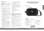
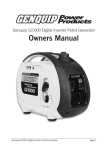
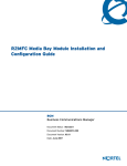
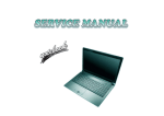
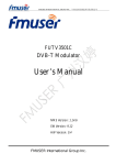
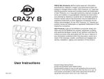
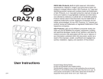
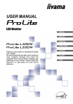
ENGLISH
Figure 2 - control panel
an output of between 13V and 21V DC. Refer to the User Manual of the Solar Panel or Wind
Generator for detailed instructions on how to recharge batteries.
Display Bar
Figure 4
www.freeplayenergy.com
USER INSTRUCTIONS & SERVICE MANUAL
Battery Level
Display Switch
12V DC Output
Cigarette Lighter Socket
1. INTRODUCTION
2. IMPORTANT SAFETY INFORMATION
3. FEATURES
Note: It is strongly recommended that you recharge you FreeCharge after use.
4. OPERATION
4.1 display and controls
4.2 first time use
4.3 recharging the Freecharge Weza
4.4 operating DC appliances
4.5 jump-starting
5. MAINTENANCE AND STORAGE
Negative Jumper Terminal
5. FREECHARGE MAINTENANCE AND STORAGE
5.1 battery care
5.2 battery removal and disposal
5.1 Battery Care
The FreeCharge contains a sealed Lead Acid battery that should not be stored in a fully discharged state.
Prolonged storage of a totally discharged Lead Acid battery may damage it.
Fully recharge the Freecharge before storage.
The battery self-discharge rate is 5% per month when the unit is stored at a temperature of 68°F. The selfdischarge rate increases with an increase in ambient temperature.
In order to prolong battery life when not in regular use, recharge the FreeCharge every 3 months.
DC Input Socket
6. PRODUCT SPECIFICATIONS
7. CUSTOMER SUPPORT AND WARRANTY
Positive Jumper Terminal
4.4 Operating DC Appliances
5.2 Battery removal and disposal
The FreeCharge can power many 12 V DC accessories via the cigarette lighter output socket (Figure 5).
The battery inside the FreeCharge is a sealed lead-acid battery. It needs to be removed at the end of its
useful life and either recycled or disposed of in accordance with local regulations.
When the battery needs replacing, remove it according to the instructions provided in the FreeCharge
Service Manual. If you have any questions or problems concerning your unit, please contact the Freeplay
Customer Support center.
8. FAQ & TROUBLE SHOOTING
4. OPERATION
4.1 Display and Controls
9. SERVICE MANUAL
1. INTRODUCTION
Congratulations on purchasing the FreeCharge Weza Portable Energy Source.
The FreeCharge Weza Portable Energy Source is the only booster pack you will ever need. It
incorporates failsafe Freeplay technology, in the form of a step charge input, with both AC and DC recharge
capability.
The FreeCharge provides a truly Portable Energy Source in one compact, rugged unit, for emergency or
recreational use, anytime, anywhere.
2. IMPORTANT SAFETY INFORMATION
Read these instructions completely before using the FreeCharge and save them for future reference. Read
them in conjunction with the user manuals of the particular devices being powered by Freecharge.
The FreeCharge contains a sealed LEAD-ACID battery that must be disposed of properly at the end of its
useful life.
! Warning: During jump-starting, the receiving lead-acid battery may release explosive gases - ensure that
it is well ventilated. Always follow the specific instructions in this manual each time you jump-start using the
FreeCharge.
General Precautions:
#
#
#
#
#
#
#
When storing the FreeCharge ensure that it is out of reach of children.
When connected to the FreeCharge, the jumper cable clamps may cause sparks if touched together.
This could cause damage to the unit.
Never charge or boost a frozen battery.
Do not submerge the FreeCharge in water.
Do not operate in the vicinity of flammables
Do not expose the FreeCharge to temperatures over 104F (40C)
The lead-acid battery in the FreeCharge is a sealed unit with no free liquid acid. Batteries being jumpstarted with the FreeCharge will likely contain liquid acids, which are hazardous if spilled.
Precautions when working with batteries:
#
#
#
#
#
#
#
Figure 5
6. PRODUCT SPECIFICATIONS
Battery Level Indication
In the default state the FreeCharge battery level indication is in sleep mode to conserve battery power.
Press the battery level display button (figure 2) to display the state of charge of the FreeCharge's internal
battery. This will be indicated by the number of lights that are illuminated on the display bar. Six lights
indicate a fully charged FreeCharge battery. After 5 seconds the display bar will return to sleep mode.
Note: Battery level cannot be displayed while the FreeCharge is being charged.
Electrical Specifications
Input Effort Indication
The amount of human energy transferred into the FreeCharge via step input is indicated on the display bar
(Figure 2). The more vigorous the step input, the more energy generated, and consequently the more lights
will be illuminated. When step input stops, the display bar will show the battery level for 5 seconds before
powering down.
Charge Indication
When receiving an input charge, the display bar illuminates in a linear pattern. Once the charging source is
disconnected, the display bar will display the battery level for 5 seconds before powering down.
4.2 First Time Use
Step Input
To operate, fold out the stabilizing arms and place the FreeCharge on a level surface. Ensure that you have
a firm footing before placing a foot on the input pedal (Figure 3). At a rate of 60-70 steps per minute, the
FreeCharge will generate approximately 25 - 40 watts of energy, which is stored in the internal battery.
If the input pedal is used, the FreeCharge will immediately display the step input effort indication. Once the
step input stops, the display bar will show the battery level for 5 seconds before powering down.
Follow manufacturer’s instructions and safety procedures.
Ensure that the area around the battery is well ventilated.
Never smoke or allow a spark or flame in the vicinity of an engine or batteries.
Take care not to allow any metal objects to make contact with the positive and negative terminals
simultaneously. This will short circuit the battery causing sparks and possible damage to the battery or
electrical equipment, or even cause an explosion.
If you need to remove a battery, always remove the negative terminal from the battery first.
Wear appropriate protective clothing and avoid touching your eyes after working with batteries.
If battery acid comes into contact with skin or clothing, wash immediately with soap and water. If acid
enters your eyes, immediately flood them with cold running water and seek immediate medical
attention.
Figure 3
The FreeCharge is able to deliver a charge or operate an appliance whilst at the same time receive a
charge via the DC input charge socket or step input.
4.5 Jump-starting
! Warning: Always connect the jumper cable clamps positive to positive (red clamp to battery positive
terminal) and negative to negative (black clamp to battery negative terminal). Never connect in reverse
polarity (positive to negative) as this may cause damage to both the FreeCharge and the battery being jump
started.
! Warning: The FreeCharge's jump-start feature should only be used in 5-second bursts. A cranking
duration in excess of 5 seconds may cause damage to the FreeCharge battery. Ideally the FreeCharge
battery should be allowed to recover for at least 2 minutes between jump-start cycles.
! Warning: Always ensure the insulated clamping nuts are secured on the jump-start terminal posts when
not in use. If a metal object is placed across the terminal posts it may cause a spark or damage the battery.
Step Charge input to provide power anytime, anywhere.
Step input effort indication.
Runs 12-volt DC products via a cigarette lighter socket
Sealed, non-spill 7 amp-hour lead acid battery
Jump-starting cables designed for safe and efficient use
Internal battery level indicator
Rechargeable at home, from a boat, motor vehicle or on the move
Service tool kit
AC/DC Charging adapter
DC charging cable
The FreeCharge Weza, with its accessories and tools, is stored neatly in a rugged carry bag.
Pedal
Battery
Disconnect
Switch
Figure 6
5ft (1.6m)
200 Amps
AC/DC Charging Adapter
Full charge time
Maximum recommended on charge time
18V 1.5 Amps
8 hrs
24hrs
DC input socket
13V - 21V (2.1mm center pin positive)
Step Input power range
Step Input Peak input power
25W - 40W
48W
10.4" x 8.6" x 16.3" (264 x 218 x 414mm)
18.7 lbs (8.5 kg)
2 years
7. CUSTOMER SUPPORT AND WARRANTY
Freeplay Customer Support Center:
United States and Canada:
Dixie Sales, Tel: 1866 6977 529, e-mail: [email protected]
United Kingdom:
Tango Group, Tel: 0870 6091541, e-mail: [email protected]
Rest of the world:
e-mail: [email protected]
The Freeplay Customer Support Center provides support to FreeCharge Weza Portable Energy Source
owners. The FreeCharge Weza has been designed for easy maintenance and servicing and is supplied with
a service manual and basic tool kit.
For more information about the FreeCharge Weza Portable Energy Source and other Freeplay products
please visit our web site at: www.freeplayenergy.com
Warranty Issues
2 YEAR WARRANTY
The manufacturer undertakes that, if within 2 (two) years of purchase, this appliance or any part thereof is
proved to be defective by reason of faulty workmanship or materials, we will, at our option repair or replace
the same free of charge for labor or materials on condition that:
# Normal wear and tear
# Damage through misuse, neglect or damage as a result of alteration either internally or externally, or
damaged from improper use or used in an unsuitable environment.
# The battery, which has a warranty period of 1 year.
AC Source
The FreeCharge is supplied with a 18V 1.5A AC/DC adapter.
To charge from the AC/DC adapter, plug it into a standard AC wall outlet. Insert the DC output jack of the
adapter into the DC input socket of the FreeCharge (figure 4). The display bar lights will illuminate to
indicate that the FreeCharge is accepting a charge. After approximately 8 hours (if the battery is totally
discharged) the FreeCharge will be fully charged. Ensure that the adapter is disconnected from the
FreeCharge within 24 hours to prevent over-charging. When the adapter is disconnected, the display
bar will show battery level for 5 seconds before powering down.
Vehicles and boats:
The FreeCharge is supplied with a DC charging cable that enables charging from the cigarette lighter socket
of a vehicle or a boat with a 12 V DC system.
A meaningful charge level will only be obtained if the vehicle’s engine is running while connected to the
FreeCharge. Plug the one end of the DC charging cable into the FreeCharge's DC input socket (figure 4)
and the opposite end into the vehicle's cigarette lighter socket. The display bar will illuminate to indicate that
the FreeCharge is accepting a charge. Disconnect the DC charging cable to terminate the charging
process. The display bar will then show the battery level for 5 seconds before powering down.
Solar panels and Wind generators:
The FreeCharge can be charged from a solar panel or wind generator through the DC input socket (Figure
4).The FreeCharge has been designed to accept a DC input voltage of between 13V and 21V.
Stabilizer Arm
jump-start cable length
Cable rating
This warranty excludes:
To register your warranty online visit www.freeplayenergy.com or alternatively, fill out and post the supplied
warranty card (US & UK only).
6. FAQ & TROUBLESHOOTING
Please read this section before calling the Freeplay Customer Support Center. Both the Troubleshooting
and FAQ are designed to help you solve the most common problems and answer any questions you may
have regarding your FreeCharge Weza.
DC Source
Figure 1
12V 10 Amps (fused, self resettable)
120 Watts
# The original invoice or sales receipt (indicating the date of purchase, product type and dealer's name) is
presented together with the defective unit.
# The complete unit is returned to the manufacturer or representative, postage paid.
# All service work is undertaken by the manufacturer or appointed agents.
# Any defective unit or part shall become the property of the manufacturer.
# This warranty is in addition to your statutory rights.
! Warning: Only use the supplied Freeplay AC/DC Adapter.
Input Lever
Cigarette Lighter Output Socket
Max DC output power
Contact the relevant Freeplay Customer Support Center.
3. FEATURES
Control Panel
12V 7 Amp-hours sealed lead acid
Dimensions (H x W X L)
Weight
Warranty
A switchable voltage DC output cable (not supplied) is available as an accessory, enabling the FreeCharge
to power a range of DC appliances of up to 12V with a power consumption of up to 0.4 Amperes.
4.3 Recharging the FreeCharge
Battery
General Specifications
The FreeCharge contains a sealed, non-spill, lead-acid battery that should be kept fully charged for efficient
and effective use. The FreeCharge should be recharged when first received, after each use and every 3
months during storage. It is recommended that the FreeCharge be fully charged before planning a trip.
! Warning: Refer to the "Precautions When Working With Batteries" in the front of this manual.
#
#
#
#
#
#
#
#
#
#
#
# Crank the engine in 5 second cycles with rests in between as specified above.
Jump-starting with a discharged FreeCharge Battery:
In the event that the FreeCharge battery is in a state of discharge the step input system may be used to
charge the vehicle battery directly. To do this, follow the procedure below:
# disconnect the FreeCharge internal battery using the battery disconnect switch (figure 1) located behind
the rubber cover on the outer casing. Loosen both bolts and slide the metal switch completely to the left.
Re-tighten the bolts to retain the metal switch in the “open” position.
# Switch off the ignition and other power consuming systems and connect the jumper cables as detailed
above.
# Operate the step input pedal at a rate of 60 - 70 treads per minute for several minutes. Larger engines
may require in excess of 5 minutes of input effort in order to provide the vehicle battery with enough
energy to crank the engine. Because you have disconnected the FreeCharge internal battery, all the
energy you are generating is used to charge the vehicle battery directly.
# After the engine has started, disconnect the black negative clamp and then the red positive clamp from
the battery terminals.
# Finally, remove the jumper cables from the FreeCharge, ensure the insulated clamping nuts are secured
on the terminal posts and restore the “battery disconnect switch” to the closed position (completely to the
right) with its 2 bolts securely fastened.
Ensure that the input jack from the solar panel or wind generator is the correct size and polarity (2.1mm
center pin positive).
! Warning: The Solar panel or Wind generator output must be intended for battery charging and have
FAQ
Jump-starting with a fully charged FreeCharge battery:
The FreeCharge should ideally be fully charged before attempting to jump-start a boat or vehicle engine check the battery level by pressing battery level display button (figure 2). If there is insufficient energy,
recharge the FreeCharge from an AC or DC source.
# Turn the ignition off
# Ensure that any other power consuming systems e.g. lights, radio etc are also turned off.
# Ensure that the ‘Battery Disconnect Switch” under the rubber cover on the outer casing of the
FreeCharge is in the closed position with the bolts firmly tightened.
# Connect the jumper cables to the FreeCharge. The red cable must be attached to the red positive
terminal (+) and the black cable to the black negative terminal (-) of the FreeCharge (Figure 6). Ensure
that the clamping nuts are securely fastened to prevent the jumper cables from working loose.
# Connect the FreeCharge's red positive clamp to the positive (+) battery terminal (it usually has a red wire
connected to it). Then attach the black negative clamp to the negative (-) battery terminal.
# For best results the FreeCharge and the receiving battery should remain connected for several minutes
before attempting to crank the engine. This allows the FreeCharge to transfer energy to the receiving
battery, improving cranking performance
Q: Can the FreeCharge's internal battery be replaced?
A: Yes, please consult your service manual or contact the Freeplay Customer Support Center for advice.
Q: I have a regular 5 Amp battery charger with crocodile connector clips, can I use it to charge the
FreeCharge through the terminal posts?
A: Yes
Q: How do I know when the FreeCharge is fully charged?
A: Read all recharging instructions in the user manual. The lights on the display bar indicate charge level.
Q: How can I test the battery in the FreeCharge to see if it needs to be replaced?
A: The Manufacturer recommends that you use a 100 Amp battery load tester. Load the FreeCharge with a
100 Amp load (on terminal posts) and it should maintain at least 9 V DC.
Q: What products can my FreeCharge power or recharge?
A: most products compatible with a 12V DC power source.
Q: Is using the Step Input the only means to charge my FreeCharge?
A: No. The FreeCharge can also be charged from either a DC or AC power source.
Q: How long will it take to charge my FreeCharge from the wall socket with the AC/DC charging
adapter?
A: It will take approximately 8 hours to fully charge the FreeCharge.
Q: Can I charge my 12V DC device while the FreeCharge is being charged either through the DC
input or via the Crank?
A: Yes.
Q: What materials are used in the FreeCharge and are they recyclable?
A: The casings are made of polypropylene and glass-filled nylon. The transmission is made of a
combination of acetyl, glass-filled nylon and aluminum, while the input levers, pedal and stabilizer arms
consist of a glass-filled nylon. All plastic materials used are thermoplastics and can be recycled. The
FreeCharge contains a non-spill rechargeable Lead Acid battery, which needs to be recycled according to
regulations stipulated by your local authority. Please consult your user manual or contact the Freeplay
Customer Support Center for more advice.
Q. How long will a fully charged battery retain its charge?
A: The battery will self-discharge at 5% per month when the unit is stored at a temperature of 68°F. The selfdischarge rate increases with an increase in ambient temperature.
Q. Will I damage the FreeCharge if I crank the pedal too fast?
A. No, the faster you crank the more energy you store in the internal battery.
Q: Can I over-crank the unit - does it ever stop you from cranking?
A. No, you cannot over-crank the internal mechanism. It consists of simple gearbox, which drives an
alternator, providing power to the internal battery.
Q: What type of rechargeable battery is used in the FreeCharge?
A. The FreeCharge incorporates a non-spill rechargeable 12 V 7 Amp hour Lead Acid battery.
9. SERVICE MANUAL
DISASSEMBLING THE FREECHARGE WEZA
Sequence of disassembly (Figure 11)
Figure 10
Figure 9
NOTE:
# The FreeCharge is supplied with a tool kit to enable disassembly.
# Left and right components - these are defined when viewing the FreeCharge from its pedal end.
# The input levers and stabilizer arms must first be removed before the outer, and then the inner casings
can be opened. DO NOT remove the stabilizer arm pivot shaft (Figure 8, D) from the main assembly if you
are not intending to split the 2 inner casings, as the internal spring is attached to this shaft (Figure 10, A).
# The input levers and splined drive shaft have an indexing tooth (which has a rounded tip) and should only
be assembled in their correct indexed orientation(Figure 7).
# The gearbox and alternator are located under the outer left casing.
# The battery and bolts to release the control panel assembly are located under the right outer casing.
# The 5 bolts to split the inner casings (Figure 8, E) are located in the inner right casing (battery
compartment) and are accessed by removing the right outer casing.
# The drive shaft assembly, drive belt and return spring are located within the inner casings.
PART REPLACEMENT
1. Replacing an Input Lever and Pedal
Remove the input lever by unscrewing 2 bolts, one located at the pivot end of the input lever and the other
at the pedal end. Work the input lever off the drive shaft and the pedal shaft. The pedal consists of 2 halves
which can be removed once one of the input levers has been removed. The input levers and splined drive
shaft have an indexing tooth and should only be re-assembled in their correct indexed orientation (Figure 7).
The pedal halves should be assembled with the diamond pattern facing upward.
2. Replacing a Stabilizer Arm
Q: How long does the warranty last?
A. The FreeCharge has a 2 year warranty
Figure 7
considerable resistance due to the alternator magnets).
Loosen the 4 bolts and remove the alternator, drawing its 3 wires from the conduit to the battery
compartment.
Pull the rotor cup off the base plate of the replacement alternator. Bolt the base plate to its mountings on the
left inner casing. Feed the 3 wires through to the battery compartment and reconnect at the connector block
in the battery compartment (Figure 8, A). The order of connection does not matter. Replace the rotor cup
(figure 9, C). Replace the other components by reversing the disassembly procedure.
Q: Can I leave my FreeCharge charging from an AC wall charger all the time and unplug it when I
need to use it?
A: The FreeCharge should not be left on charge for longer than 24 hours.
Q: Should I discharge the FreeCharge's internal battery before recharging?
A: No. The FreeCharge contains a non-spill Lead Acid battery, which does not require total discharge before
recharging. Leaving a Lead Acid battery in a fully discharged state for an extended period of time will cause
damage to the battery and limit its life.
TROUBLESHOOTING
7. Replacing the Drive Shaft Assembly or the Drive Belt and Spring
# The FreeCharge will not accept a Charge from a DC source.
Remove the right input lever and right stabiliser arm. Remove the right side outer casing by removing its 5
bolts. Remove the battery and control panel, as described previously.
Remove the 5 bolts which lock the inner casings (figure 8, E) and the circlip and washer on the input shaft
(figure 8, C). Disconnect the 3 alternator wires at the connector block (figure 8, A). Pull away the right inner
casing feeding the alternator wires through their conduit and leaving the internal parts assembled in the left
inner casing. Unhook the spring from the stabilizer arm pivot shaft (figure 10, A) and pull the drive shaft
assembly together with the attached belt and spring free (Figure 10, B). Remove 2 bolts (figure 10, C) to
detach the belt together with the spring from the drive shaft assembly. Reverse this procedure to reassemble making sure that the belt is tracked correctly under the belt retaining bush (figure 10, D) and over
the toothed input pulley (figure 10, E) before re-hooking the spring end to the stabilizer pivot shaft (figure 10,
A). Make sure that the input lever arms are indexed correctly to the drive shaft assembly when reassembling (figure 7).
Symptom
The display bar does not illuminate to show that the FreeCharge is receiving a charge.
Possible Cause
Solution
The DC source has insufficient power to charge
the FreeCharge or is faulty. The FreeCharge will
not accept a charge from a DC source that has a
voltage lower than 13 volts.
Disconnect the FreeCharge from the DC source.
Charge the FreeCharge by using either the Step
Input or the AC charging adapter.
The voltage of the DC source is too high for the
FreeCharge (over 25 Volts) and has burnt out the
charge electronic circuitry.
Replace the control panel unit.
A faulty charging cable
Replace charging cable
Incorrect polarity
Check polarity
Remove a stabilizer arm by removing 2 bolts. Work the stabilizer arm off the stabilizer pivot shaft and the
stabilizer locking shaft. DO NOT remove the stabilizer arm pivot shaft (figure 8, D) from the main assembly if
you are not intending to split the 2 inner casings, as the internal spring is attached to this shaft.
Reverse this procedure to re-assemble.
Symptom
The display bar does not illuminate after plugging in and switching on the AC/DC adapter
A faulty AC adapter
Check or Replace the AC adapter
Remove the battery as described previously. Remove the leads to the battery disconnect switch terminals
located in the right outer casing. Disconnect the 3 alternator wires at the connector block (figure 8, A) and
release the wires from their cleats. Remove the 2 bolts that hold the control panel in place (figure 8, B). The
control panel unit can now be pulled free, feeding the cables and the 3 alternator wires through the aperture
in the right inner casing.
The control panel is replaced by reversing this procedure.
Symptom
The appliance does not operate.
120
308
028
030
032
206
114
112
214
208
116
206
108
302
206
Figure 8
Replace the internal battery
216
040
008
104
208
034
206
210
208
102
018
122
106
Solution
Recharge the FreeCharge using, either an AC
source, DC source or the step input. After charging
confirm the charge status by pressing the “Display
Battery Level” button.
124
016
104
314
036
038
006
316
# The FreeCharge cannot jump start a boat or vehicle's engine.
110
Solution
Recharge the FreeCharge using an AC or DC
source. After charging confirm the charge status
by pressing the “Display Battery Level” button.
Alternatively, disconnect the FreeCharge’s internal
battery with the ‘battery disconnect switch’ and use
the step charge input to recharge the receiving
battery directly.
The engine receiving is in poor condition.
Replace the receiving battery.
The engine's cranking amps requirements
exceeds the FreeCharge's jump start capability **
It is not possible to jump start this particular engine
using FreeCharge.
110
204
Solution
Internal gears and mechanism are damaged.
Consult the Service manual or contact the
Freeplay Customer Service Center.
# The display bar does not work
Solution
The FreeCharge is totally discharged.
Recharge the FreeCharge.
The FreeCharge internal battery is damaged.
Replace the internal battery.
The electronic circuitry is damaged.
Contact the Freeplay Customer Service Center.
004
208
PART NAME
PART No.
KEY
PART NAME
PART No.
KEY
PART NAME
PART No.
002
Left Input Lever
114-ILL-GOL
036
Stabilizer Locking Shaft
016-SS-GOL
204
Serrated Washer
200-W-S-M10
004
Left Stabilizer Arm
012-SL-GOL-A
038
Stabilizer Pivot Shaft
016-SS-GOL
206
Bolt
200-CS-M6x20
006
Left Outer Casing
002-COL-GOL
040
Positive Clamping Nut
038-PNG-GOL-RED
208
Serrated Washer
200-W-S-M6
008
Left Rear Foot
010-FBL-GOL
042
Negative Clamping Nut
038-PNG-GOL-BLK
210
Washer
200-W-M6
010
Left Front Foot
008-FFL-GOL
102
Gear Plate
005-GP-GOL
212
Countersunk Bolt
200-CS-C-M4x12
012
Left Inner Casing
001-CIL-GOL-A
104
Secondary Gear Bearing
144-SGB-GOL
214
Circlip
200-CC-EX-36
014
Control Panel Gasket
032-PG-GOL
106
Secondary Gear
142-SGP-GOL-A
216
Circlip
200-CC-EX-23
016
Right Inner Casing
003-CIR-GOL-A
108
Input Gear
140-IGH-GOL-A
218
Bolt
200-CS-M6x10
018
Right Front Foot
009-FFR-GOL
110
Alternator
100-ALT-GOL
302
Positive Jumper Cable
017-JC-GOL-A-RED
020
Right Rear Foot
011-FBR-GOL
112
Input Shaft
103-IS-GOL
304
Negative Jumper Cable
017-JC-GOL-A-BLK
022
Right Outer Casing
004-COR-GOL
114
Clutch Bearing
112-CB-GOL
306
Control Panel Unit
030-IP-GOL-A
024
Right Input Lever
115-ILR-GOL
116
Toothed Pulley
111-TP-GOL
308
Battery
300-BAT-GOL
026
Battery Switch Cover
043-BSG-GOL
118
Drive Belt
107-TB-GOL
310
Battery Switch Lead
300-BLS-GOL
028
Pedal Top
120-PT-GOL
120
Input Shaft Washer
125-ISW-GOL
312
Battery Switch
044-BS-GOL
030
Pedal Shaft
118-LB-GOL
122
Drive Shaft Assembly
102-DS-GOL-A
314
AC/DC Charging Adapter
600-ACDC-GOL
032
Pedal Bottom
121-PB-GOL
124
Return Spring
104-TS-GOL
316
DC Charging Cable
601-DCCC-GOL
034
Right Stabilizer Arm
013-SR-GOL-A
202
Bolt
200-CS-BH-M10x25
318
Selectable DC Output Adapter (not supplied)
602-SVDCO-GOL
KEY
Remove the left input lever and left stabilizer arm as described previously. DO NOT remove the stabilizer
arm pivot shaft from the main assembly if you are not intending to split the 2 inner casings, as the internal
spring is attached to this shaft.
Remove the left outer casing by removing 5 bolts.
Remove the gear plate by removing 3 bolts(Figure 9, A). The secondary gear can now be removed or
replaced. Remove the circlip from the input shaft (figure 9, B) to remove or replace the input gear.
6. Replacing the Alternator
Symptom
The display bar does not illuminate.
318
206
5. Replacing Gear Components
Possible Cause
212
206
202
# The Step Input does not work
Symptom
The Input arm is either stuck or has no resistance.
010
208
**Cranking Amps are a measure of how much power a battery can supply to start an engine at 32º F.
Possible Cause
012
002
Symptom
The engine is not turning over
Possible Cause
The FreeCharge's battery is not sufficiently
charged
312
206
208
118
304
4. Replacing the Control Panel
# The FreeCharge cannot operate or charge an appliance from is cigarette lighter DC output socket.
022
306
014
Solution
310
026
218
Remove the right input lever and right stabilizer arm as described above.
Remove the right side outer casing by removing its 5 bolts.
The casing will come away partly, as the battery is attached to it. The battery should now be visible and its 2
terminals should be accessible. Disconnect the wires from the battery by undoing the bolts and remove the
battery.
To insert a new battery, reverse the procedure above. Ensure that the wires are connected to the correct
terminals. The red wire to the positive terminal and the black wire to the negative terminal.
Possible Cause
The FreeCharge's internal battery is damaged
042
3. Replacing the Battery
# The FreeCharge will not accept a charge from the AC/DC adapter.
Possible Cause
The FreeCharge's internal battery is discharged.
020
Figure 11
218
206
202
204
210 024
Remove the right and left input lever and the right and left stabilizer arms as described above. DO NOT
remove the stabilizer arm pivot shaft from the main assembly if you are not intending to split the 2 inner
casings, as the internal spring is attached to this shaft.
Remove the right outer casing by removing 5 bolts.
Disconnect the battery as described above.
Disconnect the 3 alternator wires at the connector block (Figure 8, A).
Remove the left outer casing by removing 5 bolts.
Remove the gear plate by removing 3 bolts (Figure 9, A). Remove the secondary gear. To gain access to
the 4 bolts that fasten the alternator to the left inner casing, pull the rotor cup off its base plate (figure 9, C).
Do not lever the rotor cup off, but pull in a straight line so as not to cause damage. (There will be