1
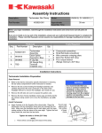
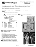
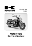
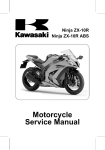
MC 06-07
SERVICE
Date: July 28, 2006
First Issued: June 27, 2006
REPLACES: Please discard MC 06-07 dated June 27, 2006
MODEL: 2004-2005 VULCAN 2000 (VN2000-A1/L-A2/L)
Page 1 of 7
®
TITLE:
ENGINE PULLEY WEAR
FACTORY DIRECTED MODIFICATION
IMMEDIATE INSPECTION
REPAIR ONLY AS REQUIRED
Eligibility
Eligible Units
Model
Vehicle Identification Number Range
VN2000-A1/L
JKBVNMA14A000032 thru 004668
VN2000-A2/L
JKBVNMA15A006008 thru 006195
Please check VSI (Vehicle Service Inquiry) in
K-Dealer for other possible repair campaigns for
eligible units.
Kawasaki will repair some units prior to you
receiving them. Repair can be verified using VSI or
by the Repair Verification. See Repair Verification
section for details.
Subject
On eligible units, the splines on the engine
pulley and/or pulley shaft may be worn due to the
type of assembly lubricant used during assembly.
This can result in the engine pulley mounting nut
not applying enough clamping force to properly
hold the pulley in place and creating abnormal
wear on the splines of the pulley and/or pulley
shaft. The worn splines may cause abnormal noise
and the vehicle may not accelerate smoothly.
Kawasaki Action
Initiate Campaign:
Kawasaki has initiated a FDM campaign to
inspect/repair all eligible units. The repair consists
of 1) removing the engine pulley to inspect the
pulley and shaft splines, replacing the pulley
and/or shaft if they are worn, and 2) applying
molybdenum grease to the pulley shaft threads
and engine pulley mounting nut seating surface
during installation and tightening the nut.
File behind the “MC” tab in your Kawasaki
“Service and Warranty” binder
©2006, Kawasaki Motors Corp., U.S.A.
Notify Registered Owners:
Kawasaki is sending a FDM letter to all
registered owners of eligible units. A copy of the
letter is printed on the last page of this bulletin.
Dealer Action
Repair Eligible Units:
Inspect/repair all eligible units including
sold units in the field and unsold units in your
dealership inventory prior to delivery to the retail
purchaser. It is the obligation of authorized
Kawasaki retail Dealers to repair eligible units in
Dealer‘s possession prior to retail sale. Failure
to comply with this obligation to repair all units
eligible for Recall or FDM campaigns by the
Dealer constitutes a breach of the Dealer Sales
and Service Agreement. Refer to Service Policies
bulletin SP 05-01. Refer to the Repair Procedure
section of the bulletin for details.
NOTE:
o If you fail to submit a Warranty Claim for a new
unit that is subsequently sold and registered, the
new owner will receive the FDM letter requesting
the return of the vehicle to you for repair.
Submit Product Registration:
Submit the product registration to Kawasaki via
K-Dealer immediately after retail sale of any eligible
unit. Be sure to supply the correct customer name
and mailing address. Kawasaki uses the product
registration information for customer notification.
Also, if you know that the customer has moved,
please submit a Customer Update via K-Dealer.
GOOD
PULLEY
SHAFT
Repair Procedure
Refer to the appropriate sections of the
Service Manual for information and procedures
related to parts removal and installation.
MODEL
SERVICE MANUAL PART NUMBER
VN2000A
99924-1320-01 thru -04
Inspection of the Engine Pulley/pulley Shaft
SCUFFING
• Remove the engine pulley cover.
• Completely loosen the drive belt
• Flatten the bent washer holding the engine
pulley mounting nut.
• Hold the engine pulley (A) with the pulley holder
(B) and remove the pulley mounting nut (C).
TEETH
SIDE WEAR
Special tools – Pulley Holder: 57001-1572
(or Rotor Holder: 57001-1672)
Grip: 57001-1591
• Remove the engine pulley from the pulley shaft
and inspect the splines on the pulley and shaft
to determine if they are worn.
Installation of the Engine Pulley
• Align the splines inside the engine pulley
with those on the pulley shaft and mount the
pulley.
• Replace the pulley washer with a new one.
• Apply molybdenum grease to the threads of
the pulley shaft and seating surface of the
engine pulley mounting nut, then tighten the
nut.
GOOD PULLEY
WORN PULLEY
+ If the pulley and shaft are not worn, follow the
instructions in Installation of Engine Pulley.
+ If only the engine pulley splines are worn,
replace the pulley following the instructions in
Installation of Engine Pulley.
APPLY
MOLYBDENUM
GREASE
+ If the pulley shaft is also worn, replace it
following the instructions in Replacement of
the Pulley Shaft.
Page 2
Torque – Engine Pulley Mounting Nut: 130 ft.lb. (177 N-m, 18 kgf-m)
• Unscrew the bolts (A) and remove the water
pipe (B).
Special Tools – Pulley Holder: 57001-1572 (or
57001-1672)
Grip: 57001-1591
NOTE:
o Rotor holder and grip (P/N 57001-1672, 570011591) are a part of the Kawasaki Essential Tool
Program and are shipping to Dealers the week
of June 26, 2006. See bulletin ST 06-01.
• Bend one side of the washer over the nut.
• Adjust drive belt deflection, and use a new
cotter pin after tightening the rear axle nut.
• Install the engine pulley cover.
Replacement of the Pulley Shaft
• Drain the engine oil and coolant.
• Remove mufflers.
• Remove:
– Oil Level Gauge/Oil Filler Cap (A)
– Oil Pipe Bolt (B)
• Remove the bolts (C) and pull down the rear
brake master cylinder (D) with the hoses
attached.
• Remove the inner transmission bolts (E) and
inner transmission cover (F).
• Loosen the transfer gear nut (A) on the pulley
shaft.
– Outer Transmission Cover Bolts (C)
• Remove the outer transmission cover (D) with
the oil pipe (E).
Special Tool – Gear Holder (B): 57001-1574
• Remove the transfer gear nut and transfer gear
(C).
• Disconnect the gear position sensor lead
connector.
• Remove the pulley shaft bearing retainer
screws and bearing retainers.
PULLEY
SHAFT
BEARING
RETAINER
SCREWS
Page 3
• Drive the pulley shaft out from the pulley side
(left side), then remove the pulley shaft with the
bearing from the right side.
NOTE:
o Bearing Driver (P/N 57001-1684) is a Special
Tool required for this FDM. Your Dealership
will be reimbursed the cost of the tool. If shaft
replacement is necessary, contact the Product
Support Hot Line to release a shaft and tool.
• Install the pulley shaft bearing retainers and
screws.
Torque – Bearing retainer screws: 61 in.-lb.
(6.9 N-m, 0.7 kgf-m)
• Install the transfer gear and washer.
• Remove the collar (A) and O-ring (B).
• Replace the transfer gear nut with a new one.
Apply molybdenum disulfide oil to the nut
thread and seating surfaces of the washer and
nut and tighten to the proper torque.
Torque – Transfer Gear Nut (Pulley Shaft): 58
fl.-lb. (78 N-m, 8.0 kgf-m)
Special Tool – Gear Holder: 57001-1574
A
• Be sure that the spring (A) and pin (B), as well
as the dowel pins (C), are in position.
B
• Insert the new pulley shaft (A) and new bearing
(B) from the right side.
B
• Replace the inner transmission cover gasket
with a new one.
A
• Apply Sealant to the grommet for the gear
position switch lead in the inner transmission
cover.
Sealant – Kawasaki Bond: 92104-0004 (Three
Bond TB1211F)
• Drive the bearing into the crankcase until it
seats.
• Tighten the inner transmission cover bolts in
the order shown below to the proper torque,
then torque the No. 1 & 2 bolts again.
A
B
Special Tool – Bearing Driver (A): 57001-1684
Steering Stem Bearing Driver (B) 57001-137
Page 4
Torque – Inner Transmission Cover Bolts: 104
in.-lb. (12 N-m, 1.2 kgf-m)
• Apply grease to new O-rings and install the
water pipes, tightening the bolts to the proper
torque.
Torque – Water Pipe Bolts: 87 in.-lb. (9.8 N-m,
1.0 kgf-m)
• Be sure the dowel pins (A) are in place and
position a new outer transmission cover
gasket.
• Install the engine pulley following the Installation
of Engine Pulley instructions.
• Install the mufflers.
• Refill the engine oil and coolant.
NOTE:
o Reference service bulletin MC 04-06 for proper
Vulcan® 2000 engine oil level checking
procedures.
Parts Information
The following parts will be required for repair.
ONLY ORDER PARTS AS NEEDED FOR FAILED
UNITS IN YOUR DEALERSHIP.
INSPECTION ONLY
Description
• Apply grease to a new O-ring for the oil pipe
in the outer transmission cover, then install the
outer transmission cover and tighten the bolts
in the order shown, along with the oil pipe bolt,
to the proper torque, then torque them again.
Part Number
Qty
Washer
92200-0017
1
Cotter Pin
550D4035
1
REPLACE ENGINE PULLEY ONLY
Description
Part Number
Qty
Washer
92200-0017
1
Cotter Pin
550D4035
1
Pulley – Belt
49079-0014
1
REPLACE ENGINE PULLEY AND SHAFT
Part Number
Qty
Washer
92200-0017
1
Cotter Pin
550D4035
1
Pulley – Belt
49079-0014
1
Shaft – Pulley
13107-0108
1
Bearing Driver
57001-1684
1
Torque – Outer Transmission Cover Bolts 104
in.-lb. (12 N-m, 1.2 kgf-m)
O-Ring
670D2014
1
O-Ring
92055-1308
1
Oil Pipe Bolt: 87 in.-lb. (9.8 N-m, 1.0 kgf-m)
O-Ring
670B2020
1
• Connect the gear position sensor lead
connector.
Gasket, Trans
11061-0017
1
Gasket, Trans
11061-0018
1
• Apply grease to a new pulley shaft O-ring (C)
and install the collar (A) and O-ring (C) on the
pulley shaft (B).
Exhaust Pipe Gasket
11061-0013
2
Bearing, Ball
92045-1190
1
Nut
92210-0138
1
Fitting
92055-0006
1
Fitting
92055-1146
1
O-Ring
670D1508
1
NOTE:
o To order the pulley shaft (P/N 13107-0108) or
bearing driver (P/N 57001-1684), you must call
the Product Support Hot Line.
Page 5
NEW
Description
Warranty Information
Repair Verification
This is a Factory Directed Modification.
Repair is authorized regardless of ownership or
warranty status. Repairs MUST BE PERFORMED
IMMEDIATELY ON ALL ELIGIBLE UNITS in the
field and during initial preparation. See the
Warranty Policies and Procedures Manual (claim
type 3 information) for detailed instructions when
submitting the Warranty Claim.
After repair or inspection, make a small punch
mark after the engine number as shown.
NOTE:
o WORN PULLEY/SHAFT PARTS MUST BE
RETURNED – CLAIMS WILL NOT BE PAID
IF THE PULLEY AND/OR SHAFT SHOWS
NO SIGNS OF DAMAGE.
o The failure rate is expected to be extremely
low.
PUNCH MARK HERE
Return parts to the following address:
Kawasaki Motors Corp., U.S.A.
ATTN: Warranty Administration, MC 06-07
9950 Jeronimo Rd.
Irvine, CA 92618
NOTE:
o Repair verification is an essential part of the
repair procedure. Along with the physical repair
verification mark, check VSI (Vehicle Service
Inquiry) in K-Dealer for other possible repair
campaigns for eligible units.
Warranty Information
Inspection
Only
Claim Type
Job Code
Causal Part
Number
Causal Part
Qty
Flat Rate Time
Failure Date
Additional
Parts
3
21313
92200-0017
Replace
Replace
Engine
Engine Pulley
Pulley Only & Pulley Shaft
3
3
21314
21315
WASHER
1
0.7 hr
0.7 hr
Same as Repair Date
92200-0017 92200-0017
550D4035
550D4035
-49079-0014
--------------------
------
3.8 hr
92200-0017
550D4035
49079-0014
13107-0108
670D2014
92055-1308
670B2020
11061-0017
11061-0018
11061-0013
(qty. 2)
92045-1190
92210-0138
92055-0006
92055-1146
670D1508
57001-1684
NEW
Item
Page 6
VULCAN® 2000 ENGINE PULLEY WEAR
FACTORY DIRECTED MODIFICATION
Dear Kawasaki Vulcan 2000 Owner:
The reason for this notice:
On eligible units, the splines on the engine pulley and/or pulley shaft may be worn due to the type of assembly
lubricant used during assembly. This can result in the engine pulley mounting nut not applying enough clamping
force to properly hold the pulley in place and creating abnormal wear on the splines of the pulley and/or pulley
shaft. The worn splines may cause abnormal noise and the vehicle may not accelerate smoothly. Our records
indicate that you have bought one of these units.
What Kawasaki and your dealer will do:
Kawasaki has initiated a Factory Directed Modification campaign to repair all affected units. The repair will consist
of 1) removing the engine pulley to inspect the pulley and shaft splines, replacing the pulley and/or shaft if they
are worn, and 2) applying molybdenum grease to the pulley shaft threads and engine pulley mounting nut seating
surface during installation and tightening the nut to the proper torque.
This repair will be made by an authorized Kawasaki motorcycle dealer at no charge. Repair time will differ depending
on the results of the inspection. The actual repair will take up to 4 hours, but may take longer due to scheduling at the
dealership and the time needed to obtain required parts. Please call your Kawasaki motorcycle dealer to schedule
an appointment and take this letter with you at that time.
If you need help:
If you have questions or concerns that your dealer is not able to resolve, please contact Kawasaki’s Consumer
Services Department:
Kawasaki Motors Corp., U.S.A.
ATTN: Consumer Services Department
P.O. Box 25252
Santa Ana, California 92799-5252
(949) 460-5688 between 8:30 a.m. and 4:45 p.m. PT Monday through Friday.
If you received this notice in error:
Our records indicate you are the current owner of the Vulcan 2000 described in this letter. If you no longer have the
vehicle described in this letter, or if it has been repaired, please help us to update our records by calling Kawasaki
toll free at (866) 802-9381 between 8:30 a.m. and 4:45 p.m. PT Monday through Friday.
We are sorry for any inconvenience, but we have taken this action in your best interest and continued satisfaction
with your Kawasaki motorcycle. Please contact your dealer if you have any questions.
Sincerely,
KAWASAKI MOTORS CORP., U.S.A.
Page 7