1
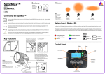
Assembly Instructions Description: Tachometer, Bar Clamp Part-Number: K53020-381 Model: VN900 B, D/ VN2000 E, F Approximate Assembly Time: 30 min Before you begin installation, read through the installation instructions and check to be sure all parts are present. If you are in doubt as to any part of the installation, please ask your authorized Kawasaki dealer to complete the installation. Please note that Kawasaki cannot assume any responsibility for damage resulting from incorrect installation. Seq. 1. Parts List Part Number Description K53020-381 2. 99-0615 3. 99-0605 4. TBD Tachometer Assembly Quick Splice Connector, Blue 4” Zip ties 22 Gauge Ring Terminal (VN2000 only) Tools Required: Qty. 1 1 3 Cross-point screwdriver Small flat blade screwdriver Wire connector crimping pliers 8mm Hex Socket 3/8“ drive Ft.lb. torque wrench (Range minimum: 20 Ft lbs) 1 Installation Instructions Tachometer Installation Preparation Parts Removal • Refer to the Service manual for specific information in removing the bar clamp components if further instruction is needed. • Remove the two screws holding the headlight assembly and carefully disconnect the 3-pin connector on the back of the headlight reflector to remove the headlight, set it aside for now. • • Remove the left side coil cover to expose the ignition coils. Remove the four chrome handlebar clamp caps and bolts and the two clamps, being careful not to move the handlebars, see side note. NOTICE It is recommended that you have an assistant stabilize the handlebars at this point to prevent the handlebars from moving away from the original position and possibly causing damage to the fuel tank Install Tachometer • Punch mark Apply 2-stroke oil to the threads of the clamp bolts. Place the aligned with tachometer onto the handlebar clamp area and reinstall the four top surface bolts. Make sure the handlebar punch mark aligns with the lower of lower mating surface of the bar clamp at the rear edge. Tighten the front clamp clamp bolts first, and then the rear bolts. Tighten the bolts to 34 Nm (25 Ft-lbs) NOTE: o There will be a small gap at the back of the clamp. • Route the wires down from the rearside of the tachometer housing through the upper fork clamp wire and hose guide and into the rear of the headlight shell. • Connect the black and red tachometer wires inside the headlight housing as indicated in the schematic below. • Route the green tachometer wire under the fuel tank and to the bottom of the front ignition coil. Remove the black wire connector from the front coil and install the green piggyback spade connector from the tachometer on the coil and reinstall the black coil wire onto the piggyback connector’s male spade terminal. Secure the wire with the supplied cable tie. Reinstall the chrome coil cover and tighten the set screw. Be sure the ignition to the motorcycle is turned off prior to making any electrical connections Coil Black Coil Wire VN900 Coil Wire Connection VN2000 Coil Wire Connection • Reconnect the 3-pin headlight plug onto the back of the headlight and reinstall the headlight assembly onto the headlight shell, making sure to hook the top edge first and firmly snapping the bottom edge closed. Align the mounting holes and re-secure the headlight ring with the two cross-point screws. • Start the engine and check the operation and lighting of the tachometer. Tachometer Wires: Red Black Green Tachometer Wires: Red Black Green WIRE SCHEMATIC FOR VN900 Motorcycle Wires: Notes: Red / Blue Stripe (Turn signal side) Cut off supplied bullet connector, and attach with supplied blue quick splice connector Black / Yellow Stripe (accessory Insert male bullet connector into double female ground) bullet connector inside headlight shell Black Coil Wire Green spade piggyback connector on to pin on coil where stock black wire was installed, reinstall black wire on to piggyback connector on coil WIRE SCHEMATIC FOR VN2000 Motorcycle Wires: Notes: Red / Blue Stripe (Turn signal side) Cut off supplied bullet connector, and attach with supplied blue quick splice connector Install on to acorn nut inside of Cut off supplied bullet connector and attach ring headlight shell terminal to wire. Be sure paint is removed from headlight shell attachment point for proper ground. Black Coil Wire Green spade piggyback connector on to pin on coil where stock black wire was installed, reinstall black wire on to piggyback connector on coil NOTICE Care and Cleaning: Do not use abrasive cleaners; wash with mild soap and warm water. Please check / adjust all screws in regular intervals. Kawasaki Motors Corp. U.S.A., June 2009