1
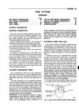
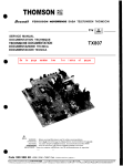
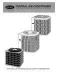
Service Manual Converter C8000 Allied Form # 80-900 Rev 2-2011 CSM-0006 July 1998 FOREWORD This manual has been prepared to provide the customer and the maintenance personnel with information and instructions on the maintenance and repair of the CLARK-HURTH COMPONENTS product. Extreme care has been exercised in the design, selection of materials and manufacturing of these units. The slight outlay in personal attention and cost required to provide regular and proper lubrication, inspection at stated intervals, and such adjustments as may be indicated will be reimbursed many times in low cost operation and trouble free service. In order to become familiar with the various parts of the product, its principal of operation, trouble shooting and adjustments, it is urged that the mechanic study the instructions in this manual carefully and use it as a reference when performing maintenance and repair operations. Whenever repair or replacement of component parts is required, only Clark· Hurth Components-approved parts as listed in the applicable parts manual should be used. Use of "will-fit" or non-a pproved parts may endanger proper operation and performance of the equipment. Clark· Hurth Components does not warrant repair or replacement parts, nor failures resulting from the use of parts which are not supplied by or approved by Clark-Hurth Components. IMPORTANT: Always furnish the Distributor with the serial and model number when ordering parts. TABLE OF CONTENTS HOW THE UNITS OPERATE .. ................ .. ...... ..... .. .. .. , .. , .. , .. , .. , . ... .. .. . ....... 1 SECTIONAL VIEWS AND PARTS IDENTIFICATION Internal Oil Flow - Torque Converter Torque Converter Assembly External Oil Flow - Converter and Transmission DISASSEMBLY OF THE TORQUE CONVERTER .... ... ...... .................. ... .. .. .8 CLEANING AND INSPECTION .. .............. . ... ........ ... .. ... ... ... ........ , ..... , .. ... .12 REASSEMBLY OF THE TORQUE CONVERTER ..... . .......... . ... ..... ..... .... .... .. 13 SERVICING MACHINE AFTER TORQUE CONVERTER OVERHAUL .. .. ........ 23 PUMP PRIMING PROCEDURE .. .. ......... .. ............. .. , .... . , ........ ... ... ........... 23 LUBRiCATION ........ ... . .. . .. ........ , ... .. , ... ,., ......... , .. , ..... , .. ... , .. .. ........... . ..... 24 TABLE OF TORQUE LIMITS ............ ....... , .. . .. ... . ........... . , .. , .. . ............ .... ... 24 TROUBLE SHOOTING GUiDE ................. ... .. .. .. ........ , ........ , .. .. ............... 25 RING GEAR INSTALLATION PROCEDURE. .......... .. .. ... . ... .... .. .... ...... ... ... ... 29 PROPER OIL CHECKING & FILLING PROCEDURE ...... .... .... ..... ..... .. ......... 30 ASSEMBLY INSTRUCTIONS.... .......................... ...... , ..... , ...................... 32 DRIVE PLATE INSTALLATION INSTRUCTIONS...... .. ................... ....... 34 & 35 NOTE: Metric Dimensions Shown in Brackets [ ]. The torque converter portion of the power train enacts an important role in delivering engine power to the driving wheels. In order to properly maintain and service these units it is important to first understand their function and how they operate. The torque converter and transmission function together and operate through a common hydraulic system. To obtain maximum serviceability they have been designed and built as separate units. It is necessary, however, to consider both units in the study of their function and operation. To supplement the text herein , and for reference use therewith, the following illustrations are provided: Internal Oil Flow Torque Converter Torque Converter Assembly External Oil Flow-Converter and Transmission TORQUE CONVERTER ASSEMBLY The torque converter assembly is composed of: (1) Torque Converter, (2) Output Shaft for driving the transmission, (3) Coupling and Flange to mount the converter charging pump to supply oil under pressure to operate transmission clutches and for converter cooling. The torque converter is composed of four members: the impeller which is the driving member, the turbine, which is the driven membe.r, the reaction member which is splined on a fixed support, and the drive disc, which couples the converter to the engine. The impeller and drive disc members form the outer shell. The turbine runs within the outer shell and is connected to the output shaft. The oil is the only connection between the turbine and impeller members. The reaction member ;s splined to the converter support which is fixed and does not rotate in either direction. A gear is splined to the impeller hub and drives through gears rotating the hydraulic pumps mounted on the converter housing cover. HOW THE UNITS OPERATE- With the engine running, the converter charging pump draws oil from the transmission sump and directs it through oil filters to the regulating valve located on top of the transmission. From the regulating valve it is then directed through the control cover on the transmission to the converter and to the transmission clutches, The pressure regulating valve'mounted on the top of the transmission remains closed until required pressure is delivered to the transmission for actuating the direction and speed clutches. This regulator valve consists of a hardened valve spool operating in a closely fitted bore. The valve spool is backed up by a spring to hold the valve spool against its seat until the oil pressure builds up to the specified pressure. The valve spool then moves towards the spring until a port is exposed along the side of the bore. The oil can then flow through this port into a distributor which directs the oil into the converter inlet port. After entering the converter, the oil is directed through the stator support to the converter cavity and exits between the turbine shaft and converter support. The oil then passes through an oil distributor which directs the oil out of the converter by way of a down stream regulator valve and then to the oil cooler. After leaving the cooler the oil is directed through a hose to the lubricating oil inlet on the transmission, then through a series of tubes to the traflsmission, bearings, and clutches. The oil then returns to the transmission sump. A safety valve is built in the transmission control cover and will open to bypass oil only if an excessive pressure is built up due to a blocked passage. The rear compartment of the converter unit also houses the converter output shaft. A flexible hose provides an overflow to the transmission sump. The three members of the torque converter are composed of a series of blades. The blades are curved in suc h a manner as to force the oil to circulate from the impeller to the turbine, through the reaction member again into the impeller. This circulation causes the tu rb ine to turn in the same direction as the impeller. Oil enters the inner side of the impeller and exits from the outer side into the outer side of the turbine. It then exits from the inner side of the turbine and after passing through the reaction member, again enters the inner side of the impeller. -1 - Converter \\Sta ll" is achieved whenever the turbine and turbine shaft are stationa ry and the engine is operating at full power or wide open throttle. CAUTION: Do not maintain "Sta ll" for more than 30 seconds at a time. Excessive heat will be genera1ed and may cause converter or transmission seal damage. In converters equipped with Lock-up clutches, a hydraulic clutch, similar to the transmission clutches is used to II I0ck"' the engine mechanically to the output shaft. This is accomp li shed by hydraulic pressure actuating the lock-up clutch wh ich in turn locks the impeller cover to the turbine hub. During lock-up the converter turns at 1 to 1 speed ratio. The down stream regulator va lve on the converter consists of a valve body and regulator spool. The spool is backed up by a spring to hold the valve until converter oi l pressure builds up to specified pressure. The valve is used to maintain a given converter pressure to insure proper performance under all conditions. The control valve assembly on the transmission consists of a valve body with selector va lve spools conrected to the steering column by exterior linkage. A detent ball and spring in the se lector spool provides four positions, one position for each speed range. A detent ball and spring in the direction spool provides three positions, one each for forward, neutral, and reverse. On certain models, this va lve also contains a shut-off va lve spool operated by an air or hydraulic cylinder located on the control cover. This valve is connected to the brake system by a hose line . When the wheel brakes are applied, air or hydraulic fluid enters the valve and overcomes a spring force. This forces the spool to shift over and block pressure from ente ring the directional clutches. In this manner a "neutral" is established w ithout moving the control levers. With the engine running and the directional control lever in neutral position, oil pressure is blocked at the control va lve, and the transmission is in neutral. Iy\ovement of th e forward and reverse spool wiH direct oil, under pressure, to e ither the forward or reverse direction clutch as desired, and the opposite one is open to relieve pressure. The direction or speed clutch assembly consists of a drum with internal gear teeth and a bore to receive a hydraulically actuated piston. A piston is inserted into the bore of the drum. The piston is "oi l tight" by the use of sealing rings. A friction disc with internal teeth is inserted into the drum and rests against the piston. Next, a disc with splines at the outer diameter is inserted. Discs are alternated until the required total is achieved. After inserting the last disc, a series of springs and pins are assembled in such a manner that these springs rest on teeth of the piston. A heavy back-up plate is then inserted and secured by a snap ring. A hub with 1.0. and 0.0. splines is inserted into the splines of discs w ith teeth on the inner diameter and a splined shaft extending through the clutch support. This hub is retained by a snap ring. The discs and inner shaft are free to increase in speed or rotated in the opposite direction as long as no pressure is present in the direction or speed clutch. To engage the clutch, as previously stated, the control valve is placed in the desired position. This allows oil under pressure to flow from the control cover va lve, through a tube in the transmission case, to a chosen clutch. Once into the drum, oil is djrected through a drilled hole into the · rear side of the piston bore. Pressure of the oil forces the piston and discs over against the heavy back-up plate. The discs, with teeth on the outer diameter, clamping agai nst discs, with teeth on inner diameter, enables the clutch drum and drive shaft to be locked to· gether and allows them to turn as a unit. There are bleed balls in the clutch drums which allow quick escape for oil when the pressure to the piston is released. The transmission gear train consists of six shafts, (1) Input Shaft, (2) Reverse Shaft, (3) Idler Shaft, (4) First and Third Shaft, (5) Second and Fourth Shaft, (6) Output Shaft. A screen mounted in a frame is positioned on the bottom of the transmission case, to scree n out any foreign material. This screen is covered by the sump pan. This pan is provided w ith magnets to catch any metallic particles. Some transmissions may have an axle declutching unit as optional equipment, this unit consists of a spl it output shaft with a slid in g splined sleeve to engage or disengage the axle. This is accomplished by manually shifting a lever in the operator's compartment which is mechanically connected to the shift fork on the clutching unit sliding sleeve. This unit, of course, is only used on the four whee l drive machine. On the front drive only or the rear wheel drive only, the output shaft is on one piece type and an output flange assembled only on the required end. -2 - LOC K -UP STA NDARD r------------------- ---- ---------------~ • _ LOC K - UP e. LOCK-UP GOV. DRIV E CLUTCH PRESSURE CONVERTER PRESSURE OIL TO COOLER LUBE AND DRAIN GOV. DRIVE -'--. lUii 1 fl ,,, ,.u-\ \~'~B~~\ \\ 69 10 65 66 I)D 59 118 -4- 61 68 DESCRIPTION ITEM QTY 5 Oil Baffle . . . . . . . . . . . . . . . . . . . . . . . . . . . . . . . • . . . Front Bearing Cup . . . . . . . . . . . . . . . . . . . . . . . • . . . Front Bearing Spacer . . . . . . • • • • • . • • . • • . • • • • • . • • • • • • .• Rear Bearing Cone . . . . . . . . . . . • . . . . . • . . . . . • . . . . . . . . . . Rear. Bearing ,~u,~ . : . . . . . . . . . . . . . . • . • • . • • • • • . • • • • . . . . 1 1 1 1 1 6 Bearing Cap 0 1 7 Bearing Cap St ud ..... , ............ • .. , . . • . . . . . • . . .. 4 Bearing Cap Stud Lockwasher . . . . . . . • . . . . . • . . . . . •. . .. 4 ... ... .. ..•... ..•.. 4 Bearing Cap Stud Nut . Flange . . . . . . . .. . . . . . . .. . .••• . ..•. • . ..••• . ... 1 Flange Washer . . ...••... ..•.. 1 Flange Nut Cotter Pin . . . . . . . • • . . . . •• . . 1 Flange ~u~; . " . . . . . . . . . . . . • • . . . . . . • . . . . . • . . . . • •• . . . 1 Flange Ring . . .......... • . . . . . • . . . . . • . . . . . . . . . . 1 Oil Seal . ... .. ..... ...•• ••• • • .. • • .••• . • •• . • • • • ... .. 1 Bearing Cap .... , .....•... , .•........ • .. . •...... , .. 1 Bearing Cap Shim .......•• . . • • • •• . • ••••. • • • ••• • . ,. AR Output Shaft ..... , .... , .. , .•.. ,., •• ,." .• , . . ,.,... 1 Output Shaft Gear ., ....... , .•.. , ..• • ' .,' • • ' .. ,., ... 1 Front Bearing Cone . . . . . • . . . . • • . . . . . • . . . . . • . .. 1 Front Bearing Snap Ring . , .... • •. , . . • • . . . . . • . 1 Oil Tube ... , , . , ... ,' ., . . , . , .. , .. , ., .. , .. , 1 Pipe Plug ........ , .... , ......... ,........ 1 Converter Housing ........... , .. , . . . . . . 1 Downstream Pressure Regulating Valve Assembly ... , , ... ' 1 Pipe P1ug .. ,., ..... , . , .. ,.,."., ........ ,., .... ... 1 Pipe Plug , ...... ,... . .... , . , ..... , . . ..• ,. 1 Reducing Bushing . . . . . . .......... • . ....•• ,. 1 Air Breather and Check Valve Assembly , .... , •. , . . . • . . . 1 Pump Hole Cover Gasket . . . . . . . . . , .. , . • ' .. , . . . . 1 Pump Hole Cover . . . .. ..................•• . • • .•• . 1 Cover Screw Lockwasher . , .. , .• ' .. • ..• ' .. . . • ' . . . . ::; Cover Screw . . ......... . ... . • . .• • • ..•••• . . . • • . • . Tube Nut ... , .. , ......... , . • .....•• ,.............. 1 Bearing Cap ., .... ,., ... . . • • •. .. ••• • • . • • •• • . • •. • ... 1 Lube Tube " 0 " Ring .... ,.. .., . • .....•.. , ..•... 1 Lube Tube .•..... . , ...... , . . •.... , .•.. , ..•.. , .. ,., 1 Lub~ Tube "9 ". ~i~ g ..... , .......... .. .. .. .... . .... , 1 Bearing Cap Ring . . ............ . ..... . . . ........ 1 Piston Ring . . . . . . . . . . . . . . . . . . • • . . . . . • . . . . . • . . . . . 1 Adaptor to Shaft Screw ..... , . , • • , .•.• •. .. • ' • • . . . • . 3 Bearing Cup . , . . .. , . , ...• ' . , . . •. , .... • ' . . . 1 Housing Rear Cover ............ . • . • ••• • •• . • •• • . • • . " 1 Cover to Housing " 0 " Ring , . ,. . •.....• •. .. , .• ,...... 1 Turbine Shaft Gear , .... , .... . .• ' . , • , • . • . . • • • • . • • . 1 Turbine Shaft , .... , .. .. • .. .. .. • .. ... . • . .. ..•.. . .. .. 1 Bearing Cone . .......... . ..... • .... , • • . . . . . • • . . . . . . 1 Bearing Cup ..... , .. .. . • •..•. , • . , •.•.•....••• . . • ,., 1 PistonRing ., .... , ............•. , ....• • . , ... • , .. ,., 1 Pipe Plug ... . ............•• , • . • •.•• .• • •• •• , .•. • 1 Ball ............ , ... , .. ,.... ..• • .....•.... 1 Support to Housing Screw ......• . ' . .• . •• ' ...• • ' . , . 8 Gear Snap Ring . . • . . . . . . . . . • . . . . . • . . . . . • • . . . . .. 1 Oil Pump Drive Gear ... , . . . . . . .••... , .•.. , . .. 1 Piston Ring Expander Spring ... . , . • • . . • • • • • . . • . • . . . . .. 1 Piston Ring . . . . . . . . . . . . . . . . . . • . . . . .. 1 Stator Support . . . . . ..•. • •.... Oil Distributor Sleeve , . . . . . . . , . , .. , .. • . , .. ,. 1 4 Housing Inspection Screw and Lockwasher . . . . . . . • • . . Housing Inspection Cover . . . . . . . . . . . . . . . . . . . . . • . . . . .. 2 Drain Plug , ... , .... , .... , . , .. , . , .... , . , .. , ..•. , .. ,. 4 Housing Inspection Cover . . . . . . . . . . . . . . . . . . . • . • . . • . .. 1 Housing Inspection Screw and l ockwasher . . . . . . . • . . . . .. 2 Bearing Cone., ......... , .... , .... ,., .... ,.. . . . . 1 l ock-Up Adaptor ...... , ...... ' . . . . . . . . . . . . • . • • . 1 Piston Ring . . . . . . . . . .•... ..•.. . 1 Bearing Cap Shim ., .... ,., . . ,............ . . ...... AR Bearing Cap Oil Seal . . . . . . . . . . . . . • . . 1 Bearing Cap Stud ........... . .... , . . . • • • • • • • • • • . . 4 . .. , . . .. , . . . 4 Bearing Cap Stud l ockwasher . . . . Bearing Cap Stud Nut ...... , .... , ., .. .. . .. • .. ..... . 4 Permanent Pump Hole Cover Screw ............ , ...... , 4 Permanent Pump Hole Cover Screw l ockw asher . , . , . . . .. 4 Permanent Pump Hole Cover . . . . . . . . . . . . . . . . . . . . . . . . . 1 Permanent Pump Hole Cover Gasket .......... , .. , .... , 1 1 2 3 4 8 9 10 11 12 13 14 15 16 17 18 19 20 21 22 23 24 25 26 27 28 29 30 31 32 33 34 35 36 37 38 39 40 41 42 43 44 45 46 47 48 49 50 51 52 53 54 55 56 57 58 59 60 61 62 63 64 65 66 67 68 69 70 71 72 73 74 75 Ring ........................... . . . . a a AR • As Required -5- ITEM 76 77 78 79 80 81 82 83 84 85 86 87 88 89 DESCRIPTION QTY Cover to Housing Screw . . . . .•..• , . . 12 Cover to Housing Screw l ockwasher , . . . . . . • • • • • . . 12 DoweIPin .. . , . . . . . , .... • ....... , .... . . , • ......•... 1 Pump Drive Shaft .,."., .. , .......... . ..•. , .•.• • .. 3 Pump Shaft Front Bearing ... , . . • . . • . . . . . . . • . . . . . . • . .. 3 PumpDrivenGear ......... , .....•. , ..... •• , ...• • . ,. 3 Driven Gear Snap Ring . . . . . • . . • • • • • • . • • • • • • . . • . • • . .. 3 Reaction Member , .. , .... , .. , ....• , .... , .•.... , •. ,. 1 Reaction Member Spacer , . , ........... .• • • • •. • .•.. ,. 1 Impeller Hub Bearing . . . . . . . . . . . . . . . . . . . . . . • . . . . Impeller Hub "0" Ring ., ......... , .... , .. , . ...... . 1 1 105 Impeller to Cover Screw lockwasher . .....•••• • . . .. , ... 32 Impeller to Cover Screw . . .. , .. . ......•. ,., .. ,. 32 Impeller Hub Screw Backing Ring ..... , . . • . • • • • • • . . . . .. 1 Impeller Hub Screw , .......... , .... , • ' ......•..... ,. 8 OiIBaHle ...... ,."., .. , ..... , ., .. , •. .. . • •• • . . •• ... 1 Oil Seal ..... . ........... , .. , .. , .. • •....... • ... . ,., 1 Pump Shaft Rear Bearing ..... , .... , ••.• ' . . . . • . . . . . . . 3 Rear Bearing Washer · Outer ..... , • • • • • . • . . . • . • • . . . . . . 3 Rear Bearing Washer - Inner , .........• . • ' . , . . • • .. , . .. 3 Pump Adaptor "0" Ring ..... , .. , ..• .••• • . • • • ••• . , . . 1 Pump Adaptor ................ , . , . . • • • . . . . . . • . . . . . . 1 Pump Drive Sleeve . , .... , ....•.. , . . • • • • . . . • • • • . . . . . 1 Pump Gasket ... , .. ,.,. . . . .....••••.....•... ". 1 Converter Charging Pump . , .. , . ..... , . • •• ' . . . . • • . . . .. 1 Pump Mounting Stud Nut. . . . . .., .. , .. .. , . .... ".... 3 Pump Mounting Stud l ockwasher ......••• ' ., ..•• ' .". 3 Pump Mounting Stud ... , .. , .. , .... , .... ... .... .. . ,. 3 Stud Nut .......... . . , ......... , .. , .•. • .. , . . . • . . . .. 4 Stud Nut Lockwasher ...... • ..••. . ...• •• . . .••• • . . , .. 4 106 Stud ... 107 108 135 136 137 138 139 Inner Washer Snap Ring . , .. , . , , . . . . . . • . • . . . . . 3 Bearing Washer Snap Ring .... , .. . . ••• • . • • ' . . . . • • . . . . 3 Oil Baffle Screw Washer ...... . .... , .....•. . ,., . • , .. , 3 Oil BaHle Screw Lockwasher . ..... .. .. ... .. . . .. . . . . ,. 3 OiIBaffieScrew ....... ,., .. ,., . • ....... •• .....•.... 3 Oil Baffle " 0 " Ring ........... ,.,.,. . .... . . .. .. . .. 1 Impeller .... , ..... , ........... , .. . . • • • • . • •••• . . , .. 1 Impeller Hub . , . , .. , . , , . , .. , . , .. , . , .. . . . .• . ... , .• ' . , 1 Impeller Hub Bearing Snap Ring , .... , . • •• •• • • , • . • • • • . • 1 Reaction Member Spacer Roll Pin . . .•. , . , .... ,. 1 Reaction Member Snap Ring ............. • . .... • .. ,. 1 Ring Gear .. ,."...... .., .... . .. • •.. • ...... 1 Ring Gear Stud ........ , .. . ... ,... . . .., .•. , ....... 24 Ring Gear Backing Plate , . . . . . . . .• . • •. . . •. 1 Ring Gear Belleville Washer . , . . . ... , ..... • ........ 96 RingGearStudNut . , ........ , .... ,." . . • . • . • . •• .... 24 Impeller Cover Bearing Cap " 0 " Ring . . .... •• .... , .. , 1 Piston Ring ,., .... . . , .. ,." .....• . , . • .... , 1 Front Bearing ..... . . , ..... ,., .... , .....•. • • • ...... 1 Impeller to Cover " 0 " Ring . . . . . , ... • .. , . . . 1 Piston Ring - Outer . , . . . . . . . . . . . . • . • • . • . • • • • • • . • • . . 1 Lock·Up Piston " 0 " Ring .. , ...... • . , .... , .•. , .. ,. 1 Lock·Up Inner Disc .......... .. ...•.......• • . ' . . • . 1 Lock-UP Inner Disc , . . . . , . . •• . . . . . .••. . . . . . . 1 Backing Plate Snap Ring . . . , .. , . . • • . . . . . • • . . . . . .. 1 Snap Ring Lock Plate . . . .. ..... . ... .. . . . . ..... . . . . 1 Screw lock Plate ... , .. ,., .. ,...... . ................ 1 Lock Plate Screw ... , .,' ... , .. , ., ...••.. •• • , . . . ..... 1 Turbine and l ock·Up Hub ...... ,.,., _• . • ,., ...... ,... 1 Turbine Hub Screw Backing Ring .... . _. • • . . . . . .. . . . . .. 1 Turbine Hub Screw .. . , .... ,......... . . . .. ... ....... 8 Turbine , ....... . . . . , . . , . . .. , ... , .... ,., ..• • ,., .... 1 Dowel Pin . . . . . . . . . . . . . . . . . • • • • • • • • • . • • • • . .. 2 140 Hub Snap Ring . . . . . . . . . . . . . . .. . . . . . • • .. . . . . . .. . . . .. , 141 142 143 144 145 Lock-Up Backing Plate ..... . . , . •.. , ., .•• • ...... • .... , l ock-Up Outer Disc ...... , . . • . • • • . . • . • • • • . • • • • • • . • •• Lock·Up Piston ,., .. ,., .. ,... . ... . . . .... . ...... . .... Piston Ring - Inner .. , .... , .. .. . . .. . •••• • • . ..• • •• . .•• Impeller Cover ..... ,....... .., ......•. , .... • • , ... Bearing Retainer ,.,.".,." .. , ....••..... • •.... Piston Ring Expander Spring . .., . . .. . . ...... . . ... Snap Ring .......... ,... . ..........•......•.. ,. Impeller Cover Bearing Cap . , . . . . , . . • • • • • • • • • • • • • . .. Impeller Cover Bearing Capscrew . . ... , . , . , .. .. , . , •. , ., 1 , 1 1 1 1 1 1 1 8 90 91 92 93 94 95 96 97 98 99 1 00 101 102 103 104 109 110 111 11 2 11 3 114 11 5 116 117 118 119 120 121 122 123 124 125 126 127 128 129 , 30 131 '32 133 134 146 147 148 149 150 .............. . .. . . .. .............. 4 1 d/ / 5 3 4 11 / .. 12 / / ~ PRESSURE REGULATING VALVE ITEM Piston Stop Piston Stop "0 " Ring Pressure Spring Piston Stop Roll Pin 2 3 4 5 6 7 8 9 10 11 12 13 14 15 DESCRIPTION QTY. 4 4 Valve to Housing Screw Valve to Housing Screw Lockwa she r Pressure Tap Pipe Plug Press ure Regulating Va lve Body Pisto n Stop Roll Pin Pipe Plug Regulating Valve Piston Piston Stop "0 " Ring Piston Stop Gasket Regulator Spring -6- 13 CHECK POINTS A. CLUTCH PRESSURE B. CONVERTER INtET C. CONVERTER OUTLET D. CONVERTER TEMPERATURE CONNECTION E. LUBE PRESSURE f. COOLER INLET PRESSURE G. COOtER OUTLET PRESSURE H. COOtER OUTLET TEMPERATURE .~-:;':., - HIgh " ...",. Lo .. " ....... _ iu<_....t~ .-.. -a, .,.. <""'_ '''''' """",., .. to ..• OVERHAUL INSTRUCTIONS FOR TORQUE CONVERTER Th e following instructions wil l cover the disassem · bly and reassembly of the torque converter in a sequence that wou ld normally be followed after the unit is removed from the machine and is to be comp letely overhauled. CAUTION: Cleanliness is of extreme importance and an absolute must in the repair and overhaul of this unit. Before a tt empt in g any repairs, the exterior of unit must be thoroughly cleaned to prevent th e possibility of dirt and foreign matter entering the mechan ism. DISASSEMBLY OF THE TORQUE CONVERTER Figure 4 Install two bolts in .threaded holes in bearin g cap. Turn bo lts even ly and remove bearing cap. Remove pvmp stud nuts and washers. Figure 2 Figure S Remove pump assemb ly and drive sleeve. Remove bearing retainer plate snap ring. Figure 3 Figure 6 Remove impeller cove r bearing cap bolts. Remove impe ll er to im pe ll er cover bolts. -8- Figure 7 Using a puller as shown in Figure 7, remove bearing retainer plate, impe ll e r cover, and turbine from tur ~ bine shaft. CAUTION: Secure impeller cover with a chain to prevent assembly from dropping. Figure 11 Remove backtng plate. Figure 12 Remove inner and outer lock-up discs Figure 8 Turbine and 'impelle r cover removed. Block impeller cover on the outer diameter and drive turbine hub from impel ler bearing. If lock -up is not used, omit Figure 9 through 15 and Figure 13 Straighten Figure 9 bolt lock lock and remove bolt, bolt cover. Figure 10 Figure 14 Remove backing plate retainer ring. Remove lock-up piston outer sealing ring and "0 " ring. -9- Figure 19 Figure 15 Remove rear housing cover bolts. Rem ove rear housing. Remove lock-up piston inner sealing ring. Figure 16 Figure 20 Remove turbine shaft bearing cap. Remove output shaft bearing cap . .., Figure 17 Remove lock wire and adaptor bolts from adaptor. Insta ll two bolts in threaded holes in adaptor. Turn bolts evenly and remove adaptor. Figure 21 Using a split puller as shown remove output shaft and outer taper bearing. Figure 18 Figure 22 lock output gears with a soft bar and remove output flange nut. Remove flange washer, \\0" ring and Remove output gear, washer and inner taper bearing from rear housing . flange . -10- / Figure 26 Remove reaction member from stator support. If re- action member is tight, threaded holes are provided to pull same from stator support. Figure 23 Remove turbine shaft and bearing assembly from converter housing . Figure 27 Remove impeller and baffle assembly from converter h'ousing. Figure 24 Remove three (3) oil baffle retainer bolts and washers from housing. Figure 28 Remove pump drive gear retainer ring. Remove pump drive gear and oil baffle from impeller hub. Figure 25 Figure 29 Remove reaction member retainer ring. Remove pump driven gear retainer rings. -11- Figure 30 Remove pump shaft rear bearing retainer ring and washer. Figure 34 If inner turbine shaft bearing cup is to be replaced remove as shown in Figure 34. CLEANING AND INSPECTION CLEAN ING Clean all parts thoroughly using solvent type cleaning fluid. It is recommended that parts be immersed in cleaning fluid and moved up and down slowly until all old lubricant and foreign material is dissolved and parts are thoroughly cleaned. Figure 31 Using a soft bar tap pump shaft assemblies from converter housing. CAUTION : Care should be exercised to avoid skin rashes, fire hazards and inhalation of vapors when using solvent type cleaners. Bearin gs Remove bearings from cleaning fluid and strike flat against a block of w ood to dislodge solidified particles of lubricant. Immerse again in cleaning fluid to flush out particles. Repeat above operation until bearings are thoroughly clean . Dry bearings using moisture-free compressed air. Be careful to direct air stream across bearing to avoid spinning. Do not spin bearings when drying. Bearings may be rotated slowly by hand to facilitate drying process. Figure 32 Remove bolts from stator supports. Housings Clean interior and exterior of housings, bearing caps, etc., thoroughly. Cast parts may be cleaned in hot solution tanks with mild alkali solutions providing these parts do not have ground or polished surfaces. Parts should remain in solution long enough to be thoroughly cleaned and heated. This will aid the evaporation of the cleaning solution and rinse water. Parts cleaned in solution tanks must be thoroughly rinsed with clean water to remove all traces of alkali. Cast parts may also be cleaned with steam cleaner. Figure 33 CAUTION : Care should be exercised to avoid inhalation of vapors and skin rashes when using alkali cleaners . Remove stator support. - 12 - REASSEMBLY OF TORQUE CONVERTER All parts cleaned must be thoroughly dried immediately by using moisture-free compressed air or soft, lintless absorbent wiping rags free of abrasive materials such as metal filings, contaminated oil or lapping compound. Instructions given below on reassembly of components are given in the sequence that must be followed in rebuilding. INSPECTION The importance of careful and thorough inspection of all parts cannot be overstressed. Replacement of all parts showing indication of wear or stress will eliminate costly and avoidable failures at a later date. Bearings Carefully inspect all rollers, cages and cups for wear, chipping or nicks to determine fitness of bearings for further use. Do not replace a bearing cone or cup individually without replacing the mating cup or cone at the same time. After inspection dip bearings in recommended type Automatic Transmission Fluid and wrap in clean lintless cloth or paper to protect them until installed. Figure 35 Install stator support. Oil Seals. Gaskets. Etc. Replacement of spring load oil seals, "0" rings, metal sealing rings, gaskets and snap rings is more economical when unit is disassembled than premature overhaul to replace these parts at a future time. Further loss of lubricant through a worn seal may result in failure of other more expensive parts of the assembly. Sealing members should be handled carefully. particularly when being installed. Cutting, scratching, or curling under of lip of seal seriously impairs its efficiency. Apply a thin coat of Permatex No. 2 on the outer diameter of the oil seal to assure an oil tight fit into the retainer. When assembling new metal type sealing rings, same should be lubricated with coat of chassis grease to stabilize rings in their grooves for ease of assembly of mating members. Lubricate all "0" rings and seals with recommended type Automatic Transmission Fluid before assembly. Gears and Shafts Figure 36 Install support sel f locking bolts and tighten 80 to 88 ft. Ibs. torque (108.5 -119.3 N.mJ. If magna-flux process is available, use process to check parts. Examine teeth on all gears carefully for wear, pitting, chipping, nicks, cracks or scores. If gear teeth show spots where case hardening is worn through or cracked, replace with new gear. Small nicks may be removed with suitable hone. Inspect shafts and quills to make certain they are not sprung, bent, or splines twisted, and that shafts are true. Housing. Covers, etc. Inspect housings. covers and bearing caps to be certain they are thoroughly cleaned and that mating surfaces, bearing bores, etc., are free from nicks or burrs. Check all parts carefully for evidence of cracks or condition which would cause subsequent oil leaks or failures. NOTE: If converter housing is replaced. see page 31 for speed sensor bushing installation. Figure 37 With pump driven gear in position, install shaft and bearing assembly through rear of case and into pump driven gear. - 13 - Figure 41 Figure 38 Install oil baffle on impeller and hub assemb ly. Use caution as not to damage oil seal. Insta ll pump dri ve gear and retainer ring. Install pvmp bearing. retainer washer and ring. " Figure 42 Install oil baffle "0 " ring. Lubricate "0 " ring with automatic transmission fluid. Figure 39 Install pump dri ven gear to shaft retainer ring. Repeat procedure for all pump shafts and gears. Figure 43 Install ' new sealing ring expander spring and oil sealing ring on support. Expander spring gap to be 180 0 from sealing ring hook joint, Figure 40 Apply a thin coat of No.2 Permatex to outer diameter of oil seal and press into bore of oil baffle. lip of seal must be upward . NOTE: Before installing oil baffle remove impeller hub bolts and install new impeller to hub "0" ring. Figure 44 Install impeller and oil baffle assembly over stator support and into converter housing. Use caution as -not to damage oil baffle 110 " ring. -14- Figure 45 Install impeller hub bearing inner race. figure 49 Using a soft bar install -turbine shaft inner bearing cup. Figure 46 Press roll pin in reaction member. Press spacer on roll pin . Figure 50 Install turbine shaft inner bearing, gear and outer bearing on shaft. Figure 47 Install reaction member on stator support and secure with retainer ring. Figure 48 Install oil baffle lockwas hers and flat washers on baffle bolts. Install bolts and washers in converter housing. Tighten evenly and securely. Install turbine shaft oil sealing ring . Block converte housing on pilot end and install turbine shaft assembly in converter housing. Figure 52 Figure 55 Position output shaft inner bearing, gear spacer and Install new " 0 11 ring on output shaft bearing cap. Install bearing cap on output shaft. gear in converter housing rear cover. Figure 56 Install stud nuts and tighten securely. This is to insure proper seating of taper bearings. Press outer bearing on output shaft. Turn rear cover over and position output shaft in output gear and spacer. Press output shaft into inner bearing. Figure 57 Apply a thin coat of Permatex No. 2 on the outer diameter of the output shaft oil seal. Press oil seal in bearing cap with lip of seal down. -]6- Loosen stud nuts. Tighten stud nuts evenly finger tight, this will prevent bearing cap from moving while selecting shims. Check gap between bearing cap and rear cover with shims used as a feeler gauge. REMOVE sufficient shims to produce a .002 " [0,050 mml tight condition. EXAMPLE: Gap is .0] 0" [0, 254 mm 1; final shim pack thickness to .008" [0, 203 mmJ . Figure 58 Install shim pack, bearing cap, stud lockwash e rs and stud nuts. Tighten nuts to 64 to 70 ft. Ibs. torque [86,8 - 94,9 N.m] . Figure 62 Using a soft bar, lock converter output gears. Install output flange, flange \\0" ring , was her, and nut. Figure 59 Install converter hou si ng to rear cover " 0 " ring . Figure 63 Tighten flange nut 250 to 300 ft. Ibs. torque [339,0406,7 N.m] . • , Figure 60 Install rear cov er and output shaft on converter hous· ing. Figure 64 If governor drive is used, install new oil seal (lip of seal up) in turbine shaft bearing cap. In stall turbine shaft outer bearing cup in bearing cap. Figure 61 Install rear cover bolts and lockwashers. Tighten bolts 41 to 45 ft. Ibs. torque [55,6 - 61,0 N.m]. -17- Figure 68 Figure 65 Install bearing cap on turbine shaft. Install stud nuts In stall \\0 " ring s on lube tube (see arrows). Using bearing cap as a guide for lube tube flange, insta ll lube tube in rear housing. and tighten securely. This is to insure proper seating of taper bearings. Figure 66 Loosen stud nuts. Tighten stud nuts eve nly finger tight, this will prevent bearing cap from moving while select- Figure 69 ing shims. Check gap betwee n bearing cap a nd re ar cover with shims used as a feeler gauge. ADD sufficient With bearing cap shims and new 110 " ring (see arrow) in posit ion install bearing cap. shims to produce a .002" [0,050 mm] loose condition. EXAMPLE: Gap is .010" [0,254 mm); final shim thick· ness to be .012" 304 m Remove bearing caD. Figure 67 Install adaptor on turbine shaft. NOTE: Adaptor will . vary for lock - up, lock - up and governor drive, and governor drive~ Assembly and disassembly is the same for all . Install bolts and tighten 26 to 29 ft. Ibs. torque [35,3 - 39,3 N.m). Figure 70 Install lockwashers and nuts. Tighten nuts 64 to 70 ft. Ibs. torque [86,S - 94,9 N.m) . If lock·up is used refer to Figure 71 through S7. If non lock ~ up is used refer to Figures 88 through 94. -1 S- Figure 71 Install lock·up piston inner sealing ring. Figure 74 Install one ( 1) friction inner disc against lock-up piston. Figure 75 Figure 72 In stall lock-up piston outer sealing outer lock joint sealing ring. "0 " ring and piston Install one ( 1) steel outer d isc. disc against steel outer disc. In stall friction inner Figure 76 Install lock-up backing plate w ith flat s ide of plate against the last friction disc. Figure 73 Install lock-up piston in impeller cove r. -19- Figure 80 Install impeller cover to turbine hub front bearing. Figure 77 Install backing plate retainer ring, with split in ring at lock plate position. Figure 81 Install turbine hub dowels. Figure 78 Install retainer ring lock, bolt lock and bolt. Tighten bolt to 12 to 16 ft. lb •. torque [16,3 - 21,7 N.m]. Bend tangs of bolt lock over head of bolt. Figure 82 Position impeller to impeller cover " 0 " ring. Figure 79 Install turbine and lock-up hub in impeller cover. Turn turbine slowly to allow lock-up hub to engage in inner lock-up discs. Do not force this operation. When turbine is in full position in lock-up discs, turn assembly over and block turbine to prevent it from dropping out of position. Figure 83 Install turbine and lock-up cover on turbine shaft. -20- Figure 84 Align holes in impeller with holes in impeller cover. Install bolts and lockwashers. Tighten bolts evenly and secure ly. Figure 88 Position new \\0 " ring (see arrow) on impeller cove r bearing cap. Install bearing cap on impeller cover. See Figure 95 for torque. Figure 85 Install bearing retainer plate on turbine shaft. Figure 89 Figure 86 ---- If lock ~u p is not used install turbine assembly on turbine shaft. Install bearing plate retainer ring. Figure 90 Figure 87 Install bearing plate oil sealing ring . Install impeller cover and bearing assembly on turbin e hub. Dri ve bearing into position . Align holes in impeller w ith impeller cover and insta ll bolts and lo~k washers. Tighten bolts eve nl y an d secu rel y. -21- Figure 91 Install bearing retainer plate. Figure 95 Install self locking bearing cap bolts in bearing cap and tighten 52 to 57 ft. lb •. torque [70,5 - 77,3 N.m]. Install bearing plate retainer ring. Figure 96 Install pump drive-sleeve and pump on converter hou sing rear cover. Install new sealing ring expander spring and oil sealing ring on bearing plate. Expander spring gap to be 180 0 from sealing ring hook joint. Figure 97 In stal l lockwashers and stud nuts. Tighten securely. Position new \\0 11 ring on impeller cover bearing cap. Install bearing cap on impeller cover. -22- SERVICING MACHINE AFTER TORQUE CONVERTER OVERHAUL Th e transmission , torque con ve rter, and its allied hydraulic system are important links in the dri ve line between th e engine and the wheels. Th e p roper operation of ei ther unit d epe nds greatly on the condition and operation of the other; therefore, whe neve r repair or overhau l of one unit is performed, the balance of the system must be considered before the job can be co nsid ered completed . After th e overhauled or repaired transmiSSion has been installed in the mac hine , the oi l cooler, and connecting hydraulic system must be thoroughly cleaned . Th is can be accomplished in several manners and a degree of judgme nt must be exercised as to the method e mployed. 5. On remote mounted torque converters remove drain plug from torque converter and inspect interior of converter ho using, gears, etc. If presence of con siderable foreign material is noted, it wi ll be necessary that con verter be removed, d isassembled and cleaned th oroug hl y . It is rea lized this entails extra labori however, such labor is a minor cost compared to cost of difficulties w hich can result from presence of such foreign materia l in the system. 6. Reassemble all components and use only ty pe oi l recommended i n lubricat ion se ct ion. Fill tran smissio n through filler ope ning until fluid comes up to LOW mark on transmission d i pstick. NOTE, The followi ng are considere d the m ini mum step s to 1. Remove LOW ER check plug , fill unlil oil runs from LOWER oil hole. Replace fi ller and level plug . Drain entire system thoroughly. 2. Di sconn ect and clean all hydraulic lines. W here feasible, hydra u lic lines shou ld be removed from machin e for cleaning. 3. 4. Run eng ine two minutes at 500-600 RPM to prime torque converter and h ydraulic lines. Reche ck leve l of fluid in transmission w ith engine r unning al idle (500-600 RPM). Repla ce oil filter elements, cl eaning out filter cases th oroughl y. The oil cooler must be thorough ly cleaned. The cooler shou ld be " back flushed " with oil and compressed air unti l all foreign material has been removed. Flushing in direction of normal oi l flow w ill not adequate ly clean th e cooler. If neces· sary, coo ler assembly should be removed from machine for cleaning, using oil, compressed air and stea m cleaner for that purpose. DO NOT u se flushing compounds for cleaning purpo ses. If Ihe dip slick is nol access ible oil leve l check plugs are provi d ed . be laken , Add qu antity necessary to bring fluid level to LOW m ark on dipstick or runs freely from LOWER oil level check plug ho le. leve l plug or d i p stick. Insla ll oil Recheck w ith hot oil (180-200" F.) [82,2 -93,3 " C), Bring oil level to FULL m ark on dipstick or ru ns freely from UPPER oil level plug. 7. Rech eck all drain plugs, lines, connections, etc., for leaks an d tigh ten w here necessa ry. CONVERTER CHARGE PUMP REPLACEMENT AI'IiD PRIMING PROCEDURE 1. Th e cause for pump failure must be found and corrected before a replacem ent pump is installed. Check all of the hoses, tubes, "0" rings . adaptors and split flanges . 2. Replace any collapsed or damaged hoses. damaged split fl ange " 0 " rings. tube " 0 " ring s and adaptors. 3. After all checks have been made and corrections comp leted install the pump. 4. See fi llin g instructions in paragraph 6 above. 5. Start the engine. Run the engine at low idle for two minu tes. watch the clutch pressure gage and listen for cav itation of the pump. 6. If the pressure does not come up, check the oil level and bleed off air from system as follows, 7. To bleed off the air from the system, loose n th e pressure gage line atthe pressure regu lating va lve or loosen th e pressure hose at th e oi l fi lter or pressure regulating va lve. Crank the engine over until the air is displaced with oi l. DO NOT START THE EN GINE. 8. If bleeding the lines does not correct the problem it may become necessary to prime t he pump. Disconnect the suction hose or pressure hose, whichever is higher, and fill the port wit h transmission oil, reconnect the hose and tighten. 9. Start the engine and check pres sure. 10. Rec heck oil level wit h hot oil (180 -200° F) with engine at idl e. Add oil as necessary to bring oi l level' to full mark. -23- SPECIFICATIONS AND SERVICE DATA-POWER SHIFT TRANSMISSION AND TORQUE CONVERTER CONVERTER OUT PRESSU RE Converter outlet oil temp. ISOe • 200" F. [82.3° • 93,3° CJ. Transmission in NEUTR AL Oil FILTRATION Full f low oil f ilt er safety by-pass. also strainer screen in sump at bottom of tran sm ission ca se. CLUTCH PRESSU RE 180·220 psi (1241 . 1 - 1516,8 kPaj - With parlt.ing brake set (l ee note) , oil temperature 1BO· • 200· F. [82.2· • 93.3° CJ. engine at idle (4 00 to 600 RPM). shi ft Ihru direction and speed clutches. All clutch pressure must be equal wi thin 5 psi. 13 4,5 kPajlf .clutch pressure varies in anyone clu tch more than 5 psi. [34,5 kPa j repair clutch. Operating specificat ions: 55 psi [379.3 kPaj minimum pressure at 2000 A.P.M. eng ine speed AN D a maximum of 70 psi J482.6 kPa] outlet pressure with engine operating at no- load gove rn ed speed. CO NTROLS Forwa rd and Reverse - CLUTC H TYPE Speed Selection - Man ua l Multiple discs, hyd raulically ac t uated, spring released, Manual NOTE : Never use .e!Vic e b rake. while making c lutch pressure c hacks . Unit s having brake actuated declutching in forwe rd and/or rever •• will not give a t,ue re ading. automatic wea r co m pensation and no adjustment. All CLUTCH INNER DISC CLUTCH OUTER DISC clutches oil cooled and lubricated. Friction. Steel. ALWAyS USE PAR KING BRAKE WHEN MAKING CLUTC H PRESSURE CHECKS. LUBRICATION TYPE O F Oil See lube Chart. CAPAC ITY Conlult Ope ra lo r' s Manua l on applicable m achine mode l for sy$lem capacity. Torqu e Converter, Transmission and alli ed hydrauli c lYltem must be conside red al a w hole to determi ne capedty. CHECK PERIOD * NO RMAL DRA IN PE RI O D RECO MMENDED LUBRICANTS FOR CLAR K·HURTH CO MPO NENTS POWER SHIFTED TR ANSM ISSION AN D TORQUI! CO NVERTERS Prevallll'lg A mbie nt T e m pe r a t ure ,. ,.,.,. Check oil leve l DA ilY w ith e ngi ne running at 500·600 RPM and oil a t 180 0 to 200 0 F. [82, 2 . 93, 3 0 C). Maintain o il level to FULL mark . Eve ry 500 hours, cha nge oil filt er e lement. Every 1000 ho urs, dra in a nd refill Iystem as folioWl: Drsin w ith oil at 150 0 to 200 0 F. [65. 6 , 93. 3° C]. (b) Drein oil filtert, re move e nd di$Csrd filter e le ments. Cleen fi lte r . he lll e nd instell new eleme nts, (c) Refill trenl miuion to lOW me.rk. (d) Run e ngine et 500·600 RPM to prime conyerter e nd lines. (e) Recheck level w ith engine running e t SOD . 6OO RPM end edd oi l to bring le vel to lOW mark. When o il tempere · ture i. hot (1 80_200 0 F.) [82,2_93,3 0 C] mek. f inel oil level check. IRING OIL lIYEl TO FULL MARK. • • _3:2""Il " :: " • b e changl'l d af'e, so and 100 houff, of o p• ,ation on new and re built or rep aired un its . Dre in tra nsmission and re mov e l ump screen. Clea n $Creen thoroughly and re place, uling new g ukets. • • ,.'" NOTE : It is recommende d that filter eleme nts (.) • • • " -0.11<010 Ia a •• , 1.-..1 w.o._ 13_•• ' Moto<s C...,.....,;on. ," '. '. '-.. 01 (.) 0-2 Ofllde 30 Temper atu,. Ib) 03 Gr.de 30 RI " gl " ' " (e) Engine Oil:· Ofede 30 API·CO/SE or CD/S F Id) MIL·L·2 , Q40Gf.da 30 II) M' L·L·2 ' 040·Grlde 30 I') MIL·L·2'04C·Gfade 10 (b) MIL·L·2 104D-G.-de 10 Te mpereturl Ie) 02 Gflde 10 "2" (d) 03 Gr.de 10 Rangl (e) Engine OI1:·Grade 10 API 'CDISE Of CO/SF (I) Oul"tolubrie a22·220 INon Phosphate Esler Fife Resis.an. A uid) Tlmperet",. :: : : : : It O ' SI' C lution BIlow " ~,. ~3" T. mp....tul. " ~,. T.mpe..tur. R.n9' ..." :: . ~:~:~~:::~ A " 6" II) ~~~~faerlO"T\OInce Syn,hetic Motor Oil PREFERRED OIL VISCOSITY: SeIaet highe$1 oil ~ty compatl • bIe with pteYtiIing arnIl;enl lempatalures and oil application chart. -. TemperatUfe rtIf91S "2" and "3" may be used to Io\w( """ MODULATED SHIFT TRANSMISSIONS: Tl 2000, 18000.24000, 28000 & 32000 lMHies IrOlnsmitslons wilh modula.ed shift use only C.J or lemperOl'Url range 3 Ilema (al & (b) 'Denon Of ' De~ ron " O. SEE CAUTION BELOW. 3000. 4000, 5000. 6000. 8000. 16000 & 34000 sories 'fllnsmllssions wi.h modulated shift use on ly C·3 or lemperalUfe range 3 item (a) only · Oe~ron. Do NOT use 'Dexron II D. SEe CAUTI ON BE LOW . CAU TION: ' OeX fon II 0 I. no. eompatlble with graphitic: eluteh pl" e l rlc:l!on materl.1UNLESS IT MEETS THE APpROVED c-3 SPECIFICATIONS. 'Oenon II D nnnol be used In the 30013, 4000,5000,6000 , 8000, '8000 or 34000 series power shift trensmlilions, or the HR28000 & HR32000 series hllYlng eon· v. rt. r Iock·up. or t he C270 . erles eonverter having lock·up UNLESS IT MEETS THE APPROVED C-3 SPECIFICATIONS . Any devletion from th'- chert ......1 haw writtMl epprovlll from the appIlc:atIon departmanl of the C.... k ·Hurth Cornponenr. Engineering and Merketlng Deplr1ment. *Severe Normal drain periods and filter change intervills are for average environmenta l and duty-cycle conditions_ or sustained high operating temperatures or very dusty atmospheric conditions will c.use .ccelerated deterioration and contamination. For extreme conditions iudgment must be used to determine the required ching. intervol., - 24 - ambianl lempetillures when sump prOOeaIM are used. Tempefa'ure range "4" should be used ody in ambianl terflleralOOl TORQUE IN (FT.-lBS.) BOLTS, CAPSCREWS, STUDS AND NUTS Grade 5 Identification, 3 Radiol Grode 8 Identificatio n, 6 Radiol Dashes 120 0 Apart on Head of Bolt Das hes 60° Aport o n Head of Boh LUBRICATED OR PLATED Grode 5 Grode 8 S ize Fin e Thread Torque Lbs. Ft./N ,m. Course Thread Torque Lbs . Ft./N.m . Torque Lbs. Ft./ N.m . Course Thread Torque Lbs. Ft./ N .m . .2500 9· 11 (12.2·14.9] 8· 10 [10.8·13.6] 11 ·1 3(14.9·1 7.6] 9· 11 ]12.2· 14.9] .3 125 16·20 ]21 . 7·27.1] 12·16116.3·21 .7( 28·32 (38.0·43.4] 26·30 (35.3·40.7] Nominal Fine Thread .3750 26· 29 (35.3·39.3] 23·25 (31.2·33 .9] 37·41 (50.2·55.6] 33·36 (44.7·48.8( .4375 41 ·45 (55.6·61.0] 37·4 1 (50.2·55.6] 58·64 [78 ,6·86.8] 52·57 (70.5·77,3] 90·99 (122,0·134 ,2] 80·88 (108 ,5· 11 9,3] .5625 91·100 (123.4·135,6] 82·90 (111 .2·122,01 128·14111 73.5·19 1,2] 115·127 [1 56,0·172.2 ] .6250 128·141 (173,5·191 .2] 113·124(153.2·168,1] 180·198 (244.0·268.4] 159·175 (215,6· 237,3] .5000 64· 70 (86 ,8·94,9] 57·63 (77 ,3·85,4] PRESSURE AND OIL FLOW CHECK SPECIFICATIONS. ALL CHECKS 0 0 MADE WITH HOT OIL (180.200 F,) [82.2 - 93.3 C.) A. B. C. D. E. Clu tch Pressure at Transmission Control Cover Transmission to Converter Line Converter· Out Pressure Temperature Gauge Connection Lubricating Pressure Converter Return Lin e Converter Pump Output See Specifications and Service Data. See Externa l Oil Fl ow Diagram. See Pressure and Oil Fl ow Checks. See Exte rn al Oil Flow Diagram. 25 p.s.i. [172.4 kPa] Maximu m at High Fre e Id le , See Externa l Oil Fl ow Diagram. See Pump Chart, TROUBLE SHOOTING GUIDE The following data is presented as an aid to loca ti ng the source of difficulty in a ma lfu nctioning u nit. It is necessary to consider the torque converter chargi ng pump, transmission , oil cooler and connecting oil lines as a comple te system when running d own the 50urce of t rouble since the p ro per operatio n of any unit the re in depends greatly on the cond ition and operation of the ot hers. By 5tudying the principle !:> of operation together with data in this section, it may be poss ible to correct any malfunction which may occu r i ' ~ the system. TROUBLE SHOOTING PROCEDURE BAS ICA LLY CONSISTS OF TWO CLASSIFICATIONS , HYDRA ULI C. MECHANICAL CHECKS MECHANICAL AND Prior to checking any part of the sY5tem from a hydraulic standpoint, the following mechanica l ch ecks should be made . 1. A check should be made 10 be sure all control lever linka9~ is properly connected and adiusted at all connecting poin ts. 2. Check shi ff le vers and rod5 for binding or restrictions in travel that wou ld prevent full engageme nt . Sh ift levers by hand at transm ission case , if fu ll engagement cannot be obtained, d iffi culty may be in control cover and vcllve assembly. HYDRAULIC CHECKS Before chec king o n the torque converter, tramm issio n an d a llied hyd raulic systems for pressures and rate of oil flow , it is eS5entiai th at the follo wing preliminary checks be made . 1. Check oil level in transmi5sion . Th is shou ld be done with oi l temperatures of 180·200 · F. (82 ,2.93,3 : C.1. DO NOT ATTEMPT THESE CHECKS WITH COLD OIL To bring the oil temperature to this specification it is necessary to either work the machine or " stall" out the con ver ter. Where the former me ans is impractical, the laller means shou ld be employed as follow s: En gage shift le ver s in fo rward an d high 5peed and apply brakes. Accele rate engine half to three.quarter throttle . Ho ld stall until de sire d converter ou tlet temperature is reached. CAU TIO N: FOR AN EXCESSIVE LENGTH OF TIME W ILL OVERHEAT THE CONVERTER, -25- FUll THROTTLE STAll SPEEDS PRESSURE AND OIL FLOW CHECKS Whenever improper performance is evident the following basic pressure and oil flow checks should be performed and recorded. It is also recommended that these checks be taken periodically as a preventative maintenance measure. Doing so will permit possible detection of difficulties in advance of actual breakdown, thus permitting scheduling of repair operation. Likewise, repair of minor difficulties can be made at considerably less cost and down-time than when delayed until major and complete breakdowns occur. Analyzing the results of these checks by comparison with specifications and with each other will indicate in most cases the basic item or assembly in the system as the source of difficulty. Further checking of that assem~y will permit isolation of the specific cause of trouble. (SEE PLUMBING AND CHECK POINT DIAGRAM) OIL PRESSURE AT CONVERTER OUT PORT. Install hydraulic pressure gauge at PRESSURE connection on Converter Regulator Valve or at CONVERTER OUT pressure tap. (All models do not have pressure regulating valves.) Check and record oil pressure at 2000 RPM and at maximum speed (engine at full throllle) (see instructions on Stalling Converter previously listed). CONVERTER MODEL MINIMUM CONVERTER OUT PRESSURE MAXIMUM CONVERTER OUT PRESSURE C· 5000 ........................................... 55 p.s.i. [379.3 kPa) 70 p.s.i. [482,6 kPa) C.8000 ........................................... 55 p.s.i. [379,3 kPa) 70 p .•. i. [482,6 kPa) C.16000......................................... 55 p ••• i. [379,3 kPa) 70 p ••• i. [482.6 kPa) If a flow meter is available, install in line between converter charging pump and oil filters . Flow meter must be able to withstand 300 p,s.L [2068.4 kPa). Disconnect hose between pump and filter at filter end and using suitable fittings connect to pressure port of tester. Install hose between filter and tester, connecting same to reservoir port of tester. DO NOT USE TESTER LOAD VALVE AT ANYTIME DURING TEST, When taking flow reading , all readings should be taken on·the first (left) half of flow gauge, Wheneve r the needle shows on the right half of gauge, correct by switching to higher scale. If a flow meter is not available for checking converter pump output. proceed with manual transmission and converter checks, If the converter shows leakage within specifications and clutch pressures (180 to 220 p,s,L) [1241 ,1 . 1516,8 kPa) are all equal within 5 p,s: L [34.5 kPa) refer to paragraph on Low Converter Charging Pump Output, PUMPS ARE RATED AT 2000 RPM - NOMINAL PUMP RATINGS, Refer to Vehicle Manufacture Manual for specific pump output. C·5000 C·8000 C·16000 21 G .P.M, 21 G,P.M . 40 G,P,M, 31 G.P.M. 31 G.P,M, 50 G,P.M . 40 G.P.M. 65 G.P.M. Pump output listed applies to a new pump in each caSe. A 20% tolerance below this figure is permissible; however. if pump output is more than 20% below specification the pump must be replaced or rebu i lt. -26- TRANSMISSION CLUTCH lEAKAGE Check clutch pressures at low engine id le w ith oil at operating temperatures 180 - 200" F. [82, 2 - 93, 3" C]. Engine speed must remain constant during entire leakage check. Shift lever into for ward 4 or 8 speeds. Record pressures. Shift lever in reverse and 1 st. Record pressure. All pressure must be equal within 5 p .s.i. [34.5 kPa] . If clutch pressure varies in anyone clutch more than 5 p.s .i . [34.5 kPaJ , repair clutch. If a flow meter is available install in line coming out of converter pump. See flow diagram for location of pressure on flow checks. Check pump volume at 2000 RPM and at low engine idle. Record readings. See pump vo lume specifications at 2000 RPM. Install flow meter in the line coming from transmission to con verter. Check oil vo lume at 2000 RPM and at (ow idle in the following speed selections. Record readings. Forward - low speed thru High Reverse - Low speed Subtract readings in each speed from pump volume reading to get transmiss ion clutch leakage. EXample, Pump Volume at idle Forward-low speed thru High Reverse-Low speed 8 gal. 6 gal. 6 gal. Pump volume Forward - Low speed Clutch leakage 8 gal. 6 gal. 2 ga l. If clutch leakage varies more than 1 gal. from one clutch to another, repair clutch. LEAKAGE IN TRANSMISSION CLUTCHES Leakage Leakage Leakage Leakage in 3000 in 5000 in 8000 in 16000 series series series series must must must must not not not not exceed exceed exceed exceed .4 gal. max. .4 gal. max. 6 gal . max. 7 gal. max. CONVERTER LUBE FLOW Disconnect CONVERTER DRAIN BACK line at transmission with engine running at 2000 RPM and meaSure oil into a gallon container. Measure oil leakage for 15 seconds and mult iply the volume of oil by four to get gallons per minute leakage. LEAKAGE IN CONVERTER leakage Leakage leakage leakage in in in in C270 C5000 C8000 C16000 series series series series not not not not to to to to exceed exceed exceed exceed 2 3 5 5 gal. gal. gal. gal. max. max. max. max. LOW CLUTCH PRESSURE WITH NORMAL CLUTCH LEAKAGE 1. 2. 3. 4. CAUSE low Oi I level. Broken spring in transmission regulator valve. Clutch pressure regulator valve spool stuck in open position. Faulty charging pump. 1. 2. 3. REMEDY Fill to proper level. Replace spring. Clean valve spool and sleeve. 4. See paragraph on charging pump output. LOW CLUTCH PRESSURE WITH EXCESSIVE CLUTCH LEAKAGE 1. 2. 3. 4. Broken or worn clutch piston sealing rtngs. Clutch drum bleed valve ball stuck in open position. Broken or worn sealing rings on clutch support. low converter charging pump output. -27- 1. 2. Replace sealing rings. Clean bleed valve thoroughly. 3. 4. Rep lace sealing rings. See paragraph on charging pump output. LOW CONVERTER CHARGING PUMP OUTPUT REMEDY CAUSE 2. 3. low oil level. Sump screen plugged. Air leaks at pump intake hose and connections or collapsed hose. 2. 3. Fill to proper level. Clean screen and sump. Tighten all connections or replace hose if necessary. 4. Defective oil pump. 4. Replace pump. 1. 1. LOW FLOW THROUGH COOLER WITH LOW CONVERTER IN PRESSURE 1. Defective safety by-pass valve spring. 2. Converter by-pass valve partially open. 3. Excessive converter internal leakage. See paragraph on converter lube flow. 4. Broken or worn sealing rings in transmission clutches. 1. 2. 3. 4. Replace spring. Check for worn by-pass ball seat. Remove, disassemble, and rebuild converter assembly, replacing all worn or damaged parts. See paragraph on Clutch leakage. LOW FLOW THROUGH COOLER WITH HIGH CONVERTER OUT PRESSURE 1. 2. 3. Plugged oil cooler. Indicated if transmission lube pressure is low. Restricted cooler return line. lube oil ports in transmission plugged. Indicated if transmission lube pressure is high. 1. Back flush and clean oil cooler. 2. 3. Clean out lines. Check lube lines for restrictions. OVERHEATING 1. Worn oil sealing rings. See paragraph E. 2. 3. 4. 1. Remove, d isassemble, and rebu ild converter assembly. Worn oil pump. 2. Low oil level. Pump suction line taking air. 3. Replace. Fill to proper level. Check oil line connections and tighTen securely. 4. NOISY CONVERTER 1. 2. 3. Worn coupling gears. 1. Replace. Worn oil pump. Worn or damaged bearings. 2. 3. Replace. A complete disassembly will be necessary to determine what bearing is faulty. LACK OF POWER 1. low engine RPM at converter sta ll . 1. Tune engine check governor. 2. See "Over-heating" and make same checks. 2. Make corrections as explained in "Over-Heating. -28- C & CL-8000 TORQUE CONVERTERS FLYWHEEL RING GEAR INSTALLATION PROCEDURE ® @ FLYWHEEL 230594 249087 C & CL·8000 249087 229769 230594 2.032 [51.62] 2.094 [53.18] If Backing Ring is to be replaced order Part No. 230594 Backing Plate. The 802551 Kit Includes: 1 24 96 24 1 2 249087 235050 228987 229769 802552 Ring Gear Stud Belleville Washer Stud Nut Instruction Sheet Remove all burrs from Flywheel Mounting Face and Pilot Bore, clean with solvent. 4 Install remaining studs. Tighten 33 to 36 Ibf.ft [44,8 48,8 N'm} torque. The engine Flywheel and Housing must conform to standard S.A.E. NO. 1 - S.A.E. J927 tolerance specifications for Pilot Bores, Eccentricities and Mounting Face deviations. Check engine crankshaft "End Play" , must be the same value before and after the torque converter is mounted to the engine. 5 Install Backing Plate 230594. 6 Lubricate Stud Threads, Belleville Washers and Nuts with S.A.E. #1 oit. 7 Install Belleville Washers and Elastic Stop Nuts as shown (3 washers, each stud for C & CL-5000 and HR & LHR-34000; 4 washers, each stud for C & CL-BOOo). Tighten nuts in a criss cross pattern to 25 IbHt [34 N·ml. Then tighten nuts in increments of 51bHt 16,7 N·ml in a criss cross pattern to 35 Ibf.ft 147,5 N·ml for C & CL-5000 and HR & LHR-34000 and 45lbf·h [61.0 N'm] for C & CL·8000 torque. Install three (3) Studs 235050 - equally spaced. Tighten 33 to 36 IbUt 144,8 - 48,8 N·m ] of torque. 3 Install Ring Gear 249087 by tapping lightly in place. -29- a PROPER OIL CHECKING & FILLING PROCEDURE Refer to transmission maintenance manual or lubrication chart. specified transmission fluid. Use only Fill torque convertEH' and transmission through filler opening until fluid comes up to LOW mark on transmission dipstick. NOTE: If the dipstick is not accessible oil level check plugs are provided. (See below). Remove LOWER check plug, fill until oil runs from LOWER oil hole . Replace filler and level plug . Run engine two minutes at 500-600 RPM to prime torque converter and hydraulic lines. Recheck level of fluid in transmission with engine running at idle (500-600 RPM). Add quantity necessary to bring fluid level to LOW mark on dipstick or runs freely from LOWER oil level check plug hole. Install oil level plug or dipstick. Recheck with hot oil (180-200 degrees). Bring oil level to FULL mark on dipstick or runs freely from UPPER oil level plug. FULL & LOW OIL LEVEL CHECK POINTS LOW OIL LEVEL - 30 - SPEED SENSOR BUSHING IN STALLATION REAR VIEW OF CONVERTER VIEW "S" (Output Drive Gear Sensor) Inspect at assembly. Dim . " W" from gear tooth. Stake 3 places approx. equally spaced . After curing of Loctite, speed sensor bushing must be secure with 40 Ft. Lb . [54.2 N' m] torque. VIEW " T" (Pump Drive Gear Sensor) -+-0-1 Inspect at assembly. Dim. "U" from gear tooth . Assembl e Speed Sensor Bushing in housing to specified dimension " U" or " W" with Loctite 262 and stake (3) three places. See Pump Drive and Output Gear Charts for dimensions. PUMP DRIVE RATIO RATIO 1.250 1.057 .946/25 0 .946 .800 DRIVE GEAR NO. OF TEETH 32 35 37 (25 0 PA) 37 40 DRIVEN GEAR NO. OF TEETH 40 37 35 (25 0 P.A.) 35 32 SPEED SENSOR BUSHING DEPTH "U" PER VIEW "T" 1.060 + .007 [26.9 ± .17] 1.060 + .007 [26.9 ± .17] 1.390 ± .007 [35 .3 ± .17] 1.390 + .007 [35.3 + .17] 1.390 ± .007 [35.3 ± .17] OUTPUT GEAR RATIO RATIO 1.323 1.118 1.000 .895 .846 TURBINE SHAFT & GEAR ASS'Y NO. OF TEETH 31 34 36 38 39 OUTPUT GEAR NO. OF TEETH 41 38 36 34 33 - 31 - SPEED SENSOR BUSHING DEPTH " W" PER VIEW " S" 1.060 ± .007 [26 .9 ± .1 7] 1.060 + .007 [26.9 + .17] 1.390 + .007 [35.3 ± .17] 1.390 ± .007 [35 .3 ± .17] 1.390 1, .007 [35 .3 ± .17] ASSEMBLY INSTRUCTIONS C-8000 CONVERTER "M~~I_C~N HUB AND TURBINE HUB ASSEMBLY WITH BACKING RING AND SPECIAL SELF LOCKING SCREWS GENERAL ASSEMBLY INSTRUCTIONS: 1. Clean hub mounling surface and lapped holes with solvent. Dry thoroughly being certain tapped holes are dry and clean. 2. Install backing ring and special screws to approximately .06 inch (1 ,5) of sealed position. With a calibra ted torque wrench, lighten impeller hub screws 58 to 64 Ibs. II. torque (78,6 . 86,8 N.ml and turbine hub screws 90 to 99 Ibs. It. torque [122.0 . 134.2 N.m}. Note: Assemblv of hub Piston ring and expander installation must be completed within a fifteen minute period from start of screw Installation. The screws are prepared with a coating which begins to harden after Installation In the hub holes. If not tightened to proper torque within the fifteen minute period, Insufficient screw clamping tension will result. The special screw Is to be used for one Installation only, If the screw Is removed tor any reason It must be replaced , The compound lett In the hub holes must be removed with the proper tap and cleaned with solvent, Dry hole thoroughly and use a new screw for reinstallation, VIEW OF RING JOINT Torque support bolts 80 • 88 Lbs. FI. (108,5 - 119,3 N·m.( "X" ...,,---L,,oe holes to be checked prior to assembly. Holes nlust be I"ee of dirt & burrs Must be loose internal Iii bearing No.3 elched on bearing. sharp edge t2:' ~t~~Assembl esnap ring·""~I~~~!;:i~_ 0",. Heat bushing to 200°F before assembly of bushing to co,'.r . -~ .D':----Lock- up clutch 2 bronze inner plates 1 steel outer plate Coat with type " A " oil prior to assembly. Stamped bearing Permatex studs u..,d __.I on rea r bearing cap Expander ~~(;ork. ~!~S~e~1 ""when specified" to be Ring Piston ring and expander installation Do not assemble ollset gears in any combination except those lisled below. A wrong combination may mesh but will not run properly. VIEW OF RING JOINT PIN NO. PIN NO. RATIO TURBINE TEETH OUTPUT TEETH 1.323 1.118 219417 218729 218871 218728 242637 31 3. 36 38 39 219418 218728 218871 218729 242638 38 36 3' 33 1.000 .895 .846 -32- 41 Torque outp ut <h",, _--1 Nut 250"300 Lbs. Ft. (339,0 - 406,7 N·m.1 OUTPUT SHAFT BEARINGS:Remove bearing cap screws after sealing bearing cap as noted left. Check gap between cap & housing with shims US6Q-aS feeler gage. RE MOVE sufficient shims to prod uce a .002 tight condition. EXAM PLE:-Gap is .010, final shim thickness to be .008. T URBINE SHAFT BEARINGS :- OFFSET & STRAIG HT THR U DRIVE Remove bearing cap screws after seating bearing cap as noted above. Check gap between cap & housing with shims used as a feeler gage . ADD sufficien t shims to produce a .002 loose condition . EXAM PLE:-Gap is .010, final shim thickness to be .012. TAPERED BEARING INFORMATION:GENERAL: Insu re seati ng of bearings & related parts by sealing bearing cap without using shims. CAUTION-Install all cap mounting screws when sealing bearing cap. Adjust to specifications noted right. Shaft should be rotated & housing rapped each time bearing cap is assembled to insure proper alignment of the beari ngs. NOTE: "0" Rings, adapter, adapter piston rings & lube tube should be assembled after shi mming of bearings to prevent damage to the various paris. NO. NO. RATIO DRIVE GEAR TEETH DRIVE GEAR TEETH 1.250 1.057 .946/25" .946 226844 233658 243755 222035 2337 15 32 35 37/25" PA 37 40 226845 233657 243756 222037 237167 40 37 35/25" PA 35 32 800 NOTE: .946 RATIO 25" PRESSURE ANGLE GEARS IDENTIFIED BY GROOVE ON GEAR o.D. LOCK-UP "X" GOV . DRIVE LOCK-UP & GOV. DR IVE Apply thin coating of grease between seal lips prior to assembly. ~ GENERAL ASSEMBL Y INSTRUCTIONS : 1. Assemble to parts list as to location of charging pump, fJ~nge size, wheel size , gear ratios, etc. 2. All lead In chamfers for oil seals, piston rings & " 0" Rings must be smooth & free from burrs . Inspect at assembly. 3. Lubricate all piston rings & "0" Rings at assembly . 4. Use Pe rmatex & Crane Sealer on ly where specified . 5. Apply very light coat of Permatex No. 2 to 0 .0 . of all oil seals prior to assembly . 6. After assembly of parts using Permatex or Crane Sealer, there must be no free or excess material that could en ter the oil circuit. 7. "0" Rings marked "X " have a white identification mark on the 0.0. Denotes high temperature material. _ _ LOCK·W IRE _ SE E VIEW·R Torque capscrews & lockwire together as shown , lock wire must not protrude above capscrew head. -33- C & CL8000 Series Converter Drive Plate INSTALLATION INSTRUCTIONS Proper Identification by Bolt Circle Diameter Measure the "A" dimension (Bolt Circle diameter) and order Drive Plate Kit listed below. , BOLT CIRCLE DI~\ O " ~\· k . . ,\ . . : r:JI".- INTERMEDIATE ': . 00 , \", ",,' .. ""-BACKING RING DRIVE PLATES (5) INTERMEDIATE DRIVE PLATES (6) "AM Dimension (Bolt Circle Diameter) MN Dimension (801t Circle Diameter) 15.00" [381,000 mm) diameter Kit No. 802587-10mm 16.00" [406,400 mm) diameter Kit No. 802594 W/O Nuts 16.00' [406 ,400 mm) d;ameter Ki t No. 802558-10mm 16.00" [406,400 mm) diameter Ki t No. 802590-7/16-20 16.875" [428,625 mm) diameter •• Kit No. 802609-7/16-20 17.00" [431,800 mm) diameter Kit No. 802593-10mm Each kit will include the following parts: 6 Intermediate Drive Plates 17.00" [431 ,800 mm) diameter Kit No. 802562-7/16-20 1 Backing Plate 14 Drive Plate Mounting Capscrews Instruction Sheet Each kit will include the following parts: 5 Intermediate Drive Plates 1 Drive Plate Assembly NOTE: Assembly of flexplates must be completed within a 15 minute period from start of screw installation. If the screw is removed for any reason it must be replac;ed. The adhesive left in the tapped holes must be removed with the proper tap and cleaned with solvent. Dry the hole thoroughly and use a new screw for reinstallation. 1 Backing Plate 14 Drive Plate Mounting Capscrews Instruction Sheet .. 1 pc . Drive Plate Mounting Spacer is included in Kit No. 802609. Pos~ion drive plate and weld nut assembly on Impeller cover with weld nuts toward cover. Align intermediate drive plate and backing ring with holes in impeller cover. NOTE: Two dimples 180· apart in backing ring must be out (toward engine flywheel). Install capscrews. Tighten capscrews 52-57 ft·lbs torque [70.4 - 77.1 N·m]. See page 35 for TORQUE CONVERTER TO ENGINE INSTALLATION PROCEDURE -34- TRANSMISSION TO ENGINE INSTALLATION PROCEDURE 1. Remove all burrs from flywheel mounting face and nose pilot bore. Clean drive plate surface with solvent. Dry thouroughly. 2. Check engine flywheel and housing for conformance to standard S.A.E . #1 - S.A.E J-927 and J-l033 tolerance specifications for pilot bore size, pilot bore runout and mounting face flatness. Measure and record engine crankshaft end play. 3. Install two 3.50 [88,90 mm] long converter to flywheel housing guide studs in the engine flywheel housing as shown . Rotate the engine flywheel to align a drive plate mounting screw hole with the flywheel housing access hole. 4. FLYWHEEl ll'F='lI HOUSINQ -1 ENGINE flY~~llI'1---J) .,'" FLYWHEEl FIG t Install a 4.00 [101,60 mm] long drive plate locating stud in a drive plate nut. Align the locating stud in the drive plate with the flywheel drive plate mounting screw hole positioned in Step NO.3. / ,,' STUD 5. Locate converter on flywheel housing aligning drive plate to flywheel and converter to flywheel housing. Install converter to flywheel housing screws. Tighten screws to specified torque. Remove converter to engine guide studs. Install remaining screws and tighten to specified torque. FLYWHEEl """""" 6. Remove drive plate locating stud. 7. 8. Install drive plate attaching screw. Snug screw but do not tighten. Some engine flywheel housings have a hole located on the flywheel housing circumference in line with the drive plate screw access hole. A screwdriver or pry bar used to hold the drive plate against the flywheel will facilitate installation of the drive plate screws. Rotate the engine flywheel and install the remaining seven (7) flywheel to drive plate attaching screws. Snug screws but do not tighten . After all eight (8) screws are installed, tighten each capscrew to the following torque- 7/16 capscrew 5864 ft. Ibs torque [78-86 N.m] :M-l 0 capscrews 48-55 ft. Ibs torque [65-75 N.m] . This will require rotating the engine flywheel until the full amount of eight (8) screws have been tightened. Measure engine crankshaft end play after converter has been completely installed on engine flywheel. This value must be within .001 [0,025 mm] of the end play recorded in Step No.2. SPE C I AL STUD, WASHER AND SELF LOCK NUT FURNISHED BY I!NGINE MANUFACTURER . FIG2 fLYWHEEL HOUSING FLY WHEEL IMPELLER COVER , l!INTERMEDIATE DRIVE PLATES FIG3 FIG4 -.~ I. ~ \ ~ \ ~ I ~ I •• I I I •I - 35- DRIVE PLATE F ::J- Plates To Be Installed - With Concave Side Toward Engine Flywheel. NOT l 5 Copyright 2010 Dana Holding Corporation All content is subject to copyright by Dana and may not be reproduced in whole or in part by any means, electronic or otherwise, without prior written approval. THIS INFORMATION IS NOT INTENDED FOR SALE OR RESALE, AND THIS NOTICE MUST REMAIN ON ALL COPIES. For product inquiries or support, visit www.dana.com or call 419-887-6445 For other service publications, visit www.SpicerParts.com/literature.asp For online service parts ordering, visit www.SpicerParts.com/order.asp