1
? IMPORTANT INFORMATION?
INFORMATION? KEEP FOR OPERATOR?
OPERATOR? IMPORTANT INFORMATION ?
OPERATOR AND SERVICE MANUAL
Part Number 128416
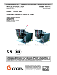
Model:
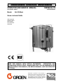
OM/SM-AH-CE
INTERNATIONAL
AH-CE Mark
Steam Jacketed Kettle
Self-contained
Stainless Steel
Gas Heated
Floor Mounted
Stationary
KEEP THIS MANUAL WITH KETTLE DOCUMENTS.
OPERATORS AND
TECHNICIANS SHOULD READ, UNDERSTAND AND FOLLOW WARNINGS AND
INSTRUCTIONS IN THIS MANUAL (THE SERVICE MANUAL AND THE OPERATOR
SECTIONS)
Information contained in this document is
known to be current and accurate at the time
of printing/creation. Unified Brands recommends referencing our product line websites,
unifiedbrands.net, for the most updated
product information and specifications.
OM/SM-AH-CE
IMPORTANT — READ FIRST — IMPORTANT
IT IS MOST IMPORTANT THAT THESE INSTRUCTIONS AND THE OPERATOR AND SERVICE
MANUALS BE CONSULTED BEFORE INSTALLING AND COMMISSIONING THE APPLIANCE.
FAILURE TO COMPLY WITH SPECIFIED PROCEDURES MAY RESULT IN DAMAGE OR THE NEED
FOR A SERVICE CALL.
THESE APPLIANCES HAVE BEEN CE MARKED ON THE BASIS OF COMPLIANCE WITH THE GAS
APPLIANCE DIRECTIVE, EMC AND LOW VOLTAGE DIRECTIVE FOR THE COUNTRIES, GAS
TYPES AND PRESSURES AS STATED ON THE DATA PLATE.
THESE APPLIANCES MUST BE INSTALLED BY A COMPETENT PERSON IN CONFORMITY WITH
THE INSTALLATION AND SERVICING INSTRUCTIONS AND NATIONAL REGULATIONS IN FORCE
AT THE TIME. PARTICULAR ATTENTION MUST BE PAID TO THE FOLLOWING:
I. E. E. REGULATIONS FOR ELECTRICAL INSTALLATIONS
ELECTRICITY AT WORK REGULATIONS
GAS SAFETY (INSTALLATION AND USE) REGULATIONS
HEALTH AND SAFETY AT WORK ACT
LOCAL AND NATIONAL BUILDING REGULATIONS
FIRE PRECAUTIONS ACT
DETAILED RECOMMENDATIONS ARE CONTAINED IN INSTITUTE OF GAS ENGINEERS
PUBLISHED DOCUMENTS: IGE/UP/1, IGE/UP/2, BS6173 AND BE5440.
FURTHERMORE, IF A NEED ARISES TO CONVERT THE APPLIANCE FOR USE WITH ANOTHER
GAS, A COMPETENT PERSON MUST BE CONSULTED. THOSE PARTS WHICH HAVE BEEN
PROTECTED BY THE MANUFACTURER MUST NOT BE ADJUSTED BY THE USER.
USERS SHOULD BE CONVERSANT WITH THE APPROPRIATE PROVISIONS OF THE FIRE
PRECAUTIONS ACT AND THE REQUIREMENTS OF THE GAS SAFETY REGULATIONS. IN
PARTICULAR THEY SHOULD BE AWARE OF THE NEED FOR REGULAR SERVICING BY A
COMPETENT PERSON TO ENSURE THE CONTINUED SAFE AND EFFICIENT PERFORMANCE OF
THE APPLIANCE.
WARNING:
TO PREVENT SHOCKS, ALL APPLIANCES GAS OR ELECTRIC, MUST BE
EARTHED.
UPON COMPLETION OF THE INSTALLATION, THE OWNERS MANUAL SHOULD BE HANDED TO
THE USERS AND THE INSTALLER SHOULD INSTRUCT THE RESPONSIBLE PERSON(S) IN THE
CORRECT OPERATION AND MAINTENANCE OF THE APPLIANCE.
THIS EQUIPMENT IS ONLY FOR PROFESSIONAL USE, AND SHALL BE OPERATED BY
QUALIFIED PERSONS. IT IS THE RESPONSIBILITY OF THE SUPERVISOR OR EQUIVALENT TO
ENSURE THAT USERS WEAR SUITABLE PROTECTIVE CLOTHING AND TO DRAW ATTENTION
TO THE FACT THAT, SOME PARTS WILL, BY NECESSITY, BECOME VERY HOT AND WILL
CAUSE BURNS IF TOUCHED ACCIDENTALLY.
WARNING:
BEFORE REMOVING ANY PARTITION OR PANEL, ALWAYS TURN OFF THE
ELECTRIC POWER AND ALLOW THE FAN TO STOP ROTATING. BEFORE
WORKING ON ANY ELECTRICAL COMPONENT, DISCONNECT THE POWER
SOURCE FROM THE UNIT.
NOTE:
IT IS IMPORTANT THAT THE END-USER ROUTINELY EXAMINE THE FLUE
OUTLET ON A REGULAR BASIS. DEBRIS COVERING THE FLUE OUTLET CAN
CAUSE A POTENTIALLY HAZARDOUS CONDITION. REMOVE ANY FOREIGN
MATERIAL BEFORE USING THIS PIECE OF EQUIPMENT.
WARNINGS AND CAUTIONS PROVIDED IN THIS OPERATOR AND SERVICE MANUAL MUST BE
COMPLIED WITH.
2
OM/SM-AH-CE
TABLE OF CONTENTS
Section
1
1.1
1.2
1.3
1.4
1.5
1.6
1.7
1.8
1.9
1.10
1.11
2
2.1
2.2
2.3
2.4
2.5
2.6
3
3.1
3.2
3.3
3.4
3.5
3.6
3.7
3.8
3.9
3.10
3.11
3.12
3.13
3.14
3.15
3.16
3.17
3.18
3.19
3.20
4
5
5.1
5.2
5.3
Page
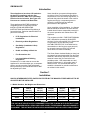
Introduction . . . . . . . . . . . . . . . . . . . . . . . . . . . . . . . . . . . . . . . . . . . . . . . . . . . . . . . . . . 4
Installation . . . . . . . . . . . . . . . . . . . . . . . . . . . . . . . . . . . . . . . . . . . . . . . . . . . . . . . . . . . 4
Model Numbers, Net Weights & Dimensions . . . . . . . . . . . . . . . . . . . . . . . . . . . . . . . . . . 5
Siting . . . . . . . . . . . . . . . . . . . . . . . . . . . . . . . . . . . . . . . . . . . . . . . . . . . . . . . . . . . . . . . . 5
Clearances . . . . . . . . . . . . . . . . . . . . . . . . . . . . . . . . . . . . . . . . . . . . . . . . . . . . . . . . . . . 5
Ventilation . . . . . . . . . . . . . . . . . . . . . . . . . . . . . . . . . . . . . . . . . . . . . . . . . . . . . . . . . . . . 5
Electrical Supply . . . . . . . . . . . . . . . . . . . . . . . . . . . . . . . . . . . . . . . . . . . . . . . . . . . . . . . 5
Gas Supply . . . . . . . . . . . . . . . . . . . . . . . . . . . . . . . . . . . . . . . . . . . . . . . . . . . . . . . . . . . 5
Water Supply . . . . . . . . . . . . . . . . . . . . . . . . . . . . . . . . . . . . . . . . . . . . . . . . . . . . . . . . . 5
Total Gas Rate . . . . . . . . . . . . . . . . . . . . . . . . . . . . . . . . . . . . . . . . . . . . . . . . . . . . . . . . 6
Injector Diameters-Natural and Propane Gas . . . . . . . . . . . . . . . . . . . . . . . . . . . . . . . . . . 6
Gas Pressure Adjustment . . . . . . . . . . . . . . . . . . . . . . . . . . . . . . . . . . . . . . . . . . . . . . . . 6
Burner Adjustment . . . . . . . . . . . . . . . . . . . . . . . . . . . . . . . . . . . . . . . . . . . . . . . . . . . . . . 6
Assembly and Conditioning . . . . . . . . . . . . . . . . . . . . . . . . . . . . . . . . . . . . . . . . . . . . . 6
Assembly . . . . . . . . . . . . . . . . . . . . . . . . . . . . . . . . . . . . . . . . . . . . . . . . . . . . . . . . . . . . 6
Gas Supply . . . . . . . . . . . . . . . . . . . . . . . . . . . . . . . . . . . . . . . . . . . . . . . . . . . . . . . . . . . 6
Electrical Supply . . . . . . . . . . . . . . . . . . . . . . . . . . . . . . . . . . . . . . . . . . . . . . . . . . . . . . . 6
Jacket Water Level/Jacket Pressure . . . . . . . . . . . . . . . . . . . . . . . . . . . . . . . . . . . . . . . . 6
Pre-Commissioning Check . . . . . . . . . . . . . . . . . . . . . . . . . . . . . . . . . . . . . . . . . . . . . . . 7
Instruction to Installer . . . . . . . . . . . . . . . . . . . . . . . . . . . . . . . . . . . . . . . . . . . . . . . . . . . 7
Servicing and Conversion . . . . . . . . . . . . . . . . . . . . . . . . . . . . . . . . . . . . . . . . . . . . . . 8
Conversion . . . . . . . . . . . . . . . . . . . . . . . . . . . . . . . . . . . . . . . . . . . . . . . . . . . . . . . . . . 10
Jacket Vacuum . . . . . . . . . . . . . . . . . . . . . . . . . . . . . . . . . . . . . . . . . . . . . . . . . . . . . . . 10
Jacket Filling . . . . . . . . . . . . . . . . . . . . . . . . . . . . . . . . . . . . . . . . . . . . . . . . . . . . . . . . . 10
Water Treatment Procedure . . . . . . . . . . . . . . . . . . . . . . . . . . . . . . . . . . . . . . . . . . . . . 10
Removal of Control Panel . . . . . . . . . . . . . . . . . . . . . . . . . . . . . . . . . . . . . . . . . . . . . . . 11
Removal of Spark Ignition Module . . . . . . . . . . . . . . . . . . . . . . . . . . . . . . . . . . . . . . . . . 11
Removal of Low Water Level Control . . . . . . . . . . . . . . . . . . . . . . . . . . . . . . . . . . . . . . 11
Removal of Gas Control Valve . . . . . . . . . . . . . . . . . . . . . . . . . . . . . . . . . . . . . . . . . . . 11
ON/OFF Switch and Reset Button . . . . . . . . . . . . . . . . . . . . . . . . . . . . . . . . . . . . . . . . . 11
Removal of Neons . . . . . . . . . . . . . . . . . . . . . . . . . . . . . . . . . . . . . . . . . . . . . . . . . . . . . 11
Removal of Thermostat . . . . . . . . . . . . . . . . . . . . . . . . . . . . . . . . . . . . . . . . . . . . . . . . . 12
Removal of Pressure Switch . . . . . . . . . . . . . . . . . . . . . . . . . . . . . . . . . . . . . . . . . . . . . 12
Low Water Level Sensor . . . . . . . . . . . . . . . . . . . . . . . . . . . . . . . . . . . . . . . . . . . . . . . . 12
Removal of The Burner . . . . . . . . . . . . . . . . . . . . . . . . . . . . . . . . . . . . . . . . . . . . . . . . . 13
Pilot Assembly . . . . . . . . . . . . . . . . . . . . . . . . . . . . . . . . . . . . . . . . . . . . . . . . . . . . . . . 13
Removal of Pressure Gauge . . . . . . . . . . . . . . . . . . . . . . . . . . . . . . . . . . . . . . . . . . . . 13
Removal of Sight Glass . . . . . . . . . . . . . . . . . . . . . . . . . . . . . . . . . . . . . . . . . . . . . . . . . 13
Safety Valve . . . . . . . . . . . . . . . . . . . . . . . . . . . . . . . . . . . . . . . . . . . . . . . . . . . . . . . . . 14
Filling Valve . . . . . . . . . . . . . . . . . . . . . . . . . . . . . . . . . . . . . . . . . . . . . . . . . . . . . . . . . 14
Fuse Replacement . . . . . . . . . . . . . . . . . . . . . . . . . . . . . . . . . . . . . . . . . . . . . . . . . . . . 14
Troubleshooting . . . . . . . . . . . . . . . . . . . . . . . . . . . . . . . . . . . . . . . . . . . . . . . . . . . . . 15
User Instructions . . . . . . . . . . . . . . . . . . . . . . . . . . . . . . . . . . . . . . . . . . . . . . . . . . . . . 17
Equipment Description . . . . . . . . . . . . . . . . . . . . . . . . . . . . . . . . . . . . . . . . . . . . . . . . . 17
Lighting and Operation . . . . . . . . . . . . . . . . . . . . . . . . . . . . . . . . . . . . . . . . . . . . . . . . . 18
Cleaning and Maintenance . . . . . . . . . . . . . . . . . . . . . . . . . . . . . . . . . . . . . . . . . . . . . . 21
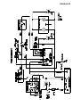
Wiring Diagram . . . . . . . . . . . . . . . . . . . . . . . . . . . . . . . . . . . . . . . . . . . . . . . . . . . . . . 23
Parts Lists . . . . . . . . . . . . . . . . . . . . . . . . . . . . . . . . . . . . . . . . . . . . . . . . . . . . . . . . . . 24
Service Log . . . . . . . . . . . . . . . . . . . . . . . . . . . . . . . . . . . . . . . . . . . . . . . . . . . . . . . . . 30
Warranty . . . . . . . . . . . . . . . . . . . . . . . . . . . . . . . . . . . . . . . . . . . . . . . . . . . . . . . . . . . . 31
3
OM/SM-AH-CE
Introduction
Users should be conversant with appropriate
provisions of the Fire Precautions Act and the
requirements of the Gas Safety Regulations. In
particular they should be aware of the need for
regular servicing by a competent person to
ensure the continued safe and efficient
performance of the Appliance.
These Appliances have been CE marked on
the basis of compliance with the Gas
Appliance Directive, EMC and Low Voltage
Directive for the Countries, Gas Types and
Pressures as stated on the Data Plate.
These appliances MUST BE installed by a
competent person in conformity with the
INSTALLATION AND SERVICING
INSTRUCTIONS and National Regulations in
force at the time. Particular attention MUST be
paid to the following:
C
I.E.E. Regulations for Electrical
Installations
C
Electricity at Work Regulations
C
Gas Safety (Installation & Use)
Regulations
C
Health and Safety at Work Act
C
Fire Precautions Act
Upon completion of the installation, the Owners
Manual should be handed to the users and the
installer should instruct responsible person(s) in
the correct operation and maintenance of the
Appliance.
This equipment is ONLY FOR PROFESSIONAL
USE, and shall be operated by QUALIFIED
persons. It is the responsibility of the Supervisor
or equivalent to ensure that users wear
SUITABLE PROTECTIVE CLOTHING and to
draw attention to the fact that, some parts will,
by necessity, become VERY HOT and will
cause burns if touched accidentally.
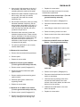
The Groen Steam Jacketed Kettle you have just
purchased has been handcrafted from the finest
materials, meticulously inspected, and carefully
tested to ensure that you receive the best
possible product. With reasonable care and
periodic maintenance, it will provide years of
faithful service. It is recommended that you
establish a timetable for periodic maintenance
as outlined in this manual.
C
Local and National Building
Regulations
Furthermore, if a need arises to convert the
Appliance for use with another gas, a competent
person must be consulted. Parts which have
been protected by the manufacturer MUST NOT
be adjusted by the User.
Section 1
Installation
UNLESS OTHERWISE STATED, PARTS PROTECTED BY THE MANUFACTURER ARE NOT TO BE
ADJUSTED BY THE INSTALLER.
1.1 Model Numbers, Net Weights and Dimensions
MODEL
WIDTH
mm (in.)
DEPTH
mm (in.)
HEIGHT
mm (in.)
WEIGHT
kg (lbs.)
CAPACITY
Liters
AH-20
933 (36.7)
991 (38.9)
1016 (39.9)
213 (468)
75.7
AH-40
972 (38.1)
1143 (44.9)
1067 (41.9)
282 (620)
151.4
AH-60
1041 (40.9)
1245 (48.9)
1245 (48.9)
432 (950)
227
AH-80
1080 (42.4)
1295 (50.9)
1410 (55.4)
486 (1070)
303
WARNING
THE UNIT MUST BE INSTALLED BY PERSONNEL QUALIFIED TO WORK WITH ELECTRICITY AND
GAS. IMPROPER INSTALLATION CAN CAUSE INJURY TO PERSONNEL AND/OR DAMAGE TO
EQUIPMENT. THE UNIT MUST BE INSTALLED IN ACCORDANCE WITH ALL APPLICABLE CODES
4
OM/SM-AH-CE
1.2 Siting
1.5 Electrical Supply
Install the appliance on a level floor in a well-lit
and draught-free position. Install the appliance in
accordance with local and/or national regulations
as listed in this manual.
1.3 Installing Clearances
This unit is designed for connection to fixed
wiring. A suitably rated isolating switch with
contact separation of at least 3 mm on both poles
must be fitted to the installation and the wiring
executed in accordance with the regulations listed
in this manual.
Minimum clearances of 150 mm from the sides of
the appliance and 150 mm from the rear of the
appliance are required if the appliance is installed
next to combustible surfaces.
Cable entry is at the lower rear on right hand side
of the appliance. Access to the terminals is
gained by removing relevant panels as described
in Section 3.5 of this manual.
Allow 1000 mm minimum clearance between the
top rim of kettle and any overlying surface.
Provide 230 VAC, 50 Hz, 1 Phase, service. Rated
input: 0.17 Amps, or 40 Watts. The electrical
schematic is located in the service compartment
and in this manual.
1.4 Ventilation
The unit must be installed in an adequately
ventilated room with provision for an adequate air
supply. The area around the appliance must be
cleared of all combustible material. For multiple
installations requirements for individual units
should be added together. Installation must
comply with applicable regulations. A competent
installer must be employed.
WARNING
THIS APPLIANCE MUST BE EARTHED.
1.6 Gas Supply
The incoming service must be of sufficient size to
supply full rate without excessive pressure drop.
A gas meter is connected to the service pipe by
the Gas Supplier. Any existing meter should be
checked by the Gas Supplier to ensure that the
meter is of adequate capacity to pass the required
rate of gas for the kettle in addition to any other
gas equipment installed.
CAUTION
THE APPLIANCE FLUE DISCHARGES
VERTICALLY FROM THE TOP OF THE UNIT.
IT MUST NOT BE DIRECTLY CONNECTED TO
A FLUE, MECHANICAL EXTRACTION
SYSTEM, OR DUCTING LEADING OUTSIDE
THE BUILDING. THE APPLIANCE IS BEST
DISCHARGED UNDER AN OPEN CANOPY
CONNECTED TO A VENTILATING SYSTEM.
The appliance governor is incorporated in the gas
control valve which is situated in the control
cabinet.
The control valve governor is suitable for both
natural and propane gases without any
conversion.
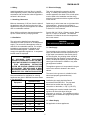
Recommendations for ventilation for catering
appliances are given in BS 5440:2 and are shown
in the table below.
Ventilation Rate
Equipment
m³/Min
ft³/Min
Range
17
600
Pastry Oven
17
600
Fryer
26
900
Grill
17
600
Steak Grill
26
900
Boiling Pan
17
600
Steamer
17
600
Sterilizing Sink
14
500
Bains Marie
11
400
Tea/Coffee Machine
8.5-14
300-500
Installation pipe work should be fitted in
accordance with IEGE/UP/2. The pipe work
should not be smaller than the gas inlet
connection on the kettle, i.e. Rp ½ (½”B.S.P.)
An isolating cock must be located close to the
appliance to allow shut down during an
emergency or servicing. The installation must be
tested for gas soundness and purged as specified
in IGE/UP/1.
1.7 Water Supply
Not applicable to these appliances.
5
OM/SM-AH-CE
1.8 Total Gas Rate
Natural
Model
(G20&
G25) KW
AH-20
22
AH-40
25
AH-60 &
40
AH-80
Propane
Natural
(G31)
BTU/hr
KW
75,100
22
85,300
22
136,500
40
NOTE: With reference to the gas rate, pressure
adjustments and conversions, this appliance is
CE-approved for use with the following gases:
Propane
BTU/hr
a) G20 natural gas may be supplied to the
appliance in Austria, Belgium, Denmark,
Finland, France, Germany, Greece, Iceland,
Ireland, Italy, Luxembourg, Norway, Portugal,
Spain, Sweden, Switzerland and the United
Kingdom.
75,100
75,100
136,500
1.9 Injector Diameters-Natural & Propane Gas
Natural Natural Propane No. of
Model Gas G20 Gas G25 Gas G31 Orifices
(mm)
(mm)
(mm) (Injectors)
AH-20
4.39
4.70
2.64
1
AH-40
4.57
4.90
2.64
1
AH-60 &
5.94
6.75
3.57
1
AH-80
b) G25 natural gas may be supplied to the
appliance in Belgium, France and the
Netherlands.
c) G31 propane gas may be supplied to the
appliance in France, Germany, Ireland, the
Netherlands, Portugal, Spain, Switzerland,
and the United Kingdom.
1.10
Gas Pressure Adjustment
A pressure test point is fitted on the burner
manifold and on the gas control valve.
AH-60 &
Model
AH-20
AH-40
AH-80
8.75
8.75
8.75
NATURAL mbar
GAS G20 in. WC
3.5
3.5
3.5
mbar
8.75
8.75
7.0
NATURAL
GAS G25 in. WC
3.5
3.5
2.8
25
25
25
PROPANE mbar
GAS G31 in. WC
10
10
10
Use of the appliance with non-approved gases in a
listed country, or use in other countries will void CE
certification.
1.11 Burner Adjustment
The burner has a primary air adjustment. The gap
should be 1/4" (6.35 mm) to 3/8" (9.53 mm).
Section 2
Assembly and Commissioning
2.1 Assembly
2.3
a) Unpack the appliance.
Before commissioning the appliance, ensure that the
electrical installation has been carried out to the
relevant regulations. (Paragraph 1.5)
b) Place on a firm, level floor. Adjust and fix
feet.
Electrical Supply
THIS APPLIANCE MUST BE EARTHED.
Caution: Shipping straps are under tension and
can snap back when cut. Take care to avoid
personal injury or damage to the unit by staples
left in the walls of the carton.
2.4
Jacket Water Level/Jacket Pressure
a) Ensure the water level is correct in the jacket, by
confirming that the level is between the marks on
the gauge glass. If the water is low, follow the
instructions under "Jacket Filling" in the servicing
section of this manual.
2.2 Gas Supply
Connect the unit to the gas supply and test for gas
soundness. For the part of the integral gas supply
down stream of the gas valve, leak detection
spray or some solution may be used with the
burners lit.
b) Check the pressure gauge. If the gauge does not
show 20 or more inches of vacuum (that is, a
reading of 20 to 30 below zero) see "Jacket
Vacuum" in the servicing section of this manual.
Caution: Ensure that the pan contains liquid when
the burners are alight.
2.5
6
Pre-Commissioning Check
OM/SM-AH-CE
a) Prior to operation, clean kettle pan with hot
water and detergent. Rinse thoroughly.
f)
b) Remove all literature and packing materials
from the interior and exterior of the unit.
g) Governor is suitable for natural and propane gas.
h) To increase pressure turn the screw inside the
governor turret clockwise, or anti-clockwise to
reduce pressure. Check the burner pressure
again after 15 minutes and adjust if necessary.
c) Ensure the open end or the elbow at the
safety valve outlet is pointed down. If not, turn
the elbow to the correct position. See Safety
Valve Operation Instructions on Page 8.
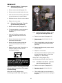
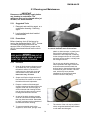
2.5.1
Remove governor cap screw on gas control
valve. See figure for governor position on valve.
i)
Disconnect pressure gauge from the test point.
j)
Re-seal the pressure test point and test for gas
soundness.
Lighting Sequence
From Initial Start Up:
a) Put a small amount of water in the kettle pan.
k) Replace governor cap screw, lid and panels.
b) Ensure gas and electricity mains are “on.”
2.5.3
c) Switch the toggle switch to the "on" position.
a) Light the unit (Paragraph 2.5.1). Check that the
controls produce a healthy spark from the
electrode to the earthing post and that ignition is
smooth and without delay.
d) Turn thermostat dial to desired setting.
e) Observe that the burners ignite by the pilot
lamp illuminating.
f)
b) Turn thermostat off and then on. Check that
burners go out when switched off and ignite
smoothly and quickly when switched back on.
Repeat several times.
If the unit does not ignite, it will lock-out. Turn
the unit off and wait for one or two minutes
before again attempting to switch it on.
c) If the unit fails to respond as described above
contact an authorized Groen service agent.
g) Press reset lock-out switch and repeat steps
(b) to (e).
2.6
h) To switch unit off, flip toggle (On/Off) switch
to the “off” position.
i)
Instruction to Installer
IMPORTANT
After installing and commissioning the
appliance, the installer should hand the user's
instructions to the user or purchaser. Ensure that
the instructions for lighting, turning off, correct
use and cleaning are properly understood.
Emphasis should be made with regard to the
location of the main gas isolating valve. The
emergency shut down procedure should be
demonstrated.
Turn gas and electricity mains off.
2.5.2
Checking Performance of Controls
Setting The Gas Pressure
a) Check gas pressure during commissioning.
Connect a pressure gauge to the pressure test
point on the burner manifold or the gas control
valve. See figure for test points.
b) When checking pressure at gas valve test
points, undo the screw a half turn and slip
tube over the nipple.
c) Turn the main gas and electricity supplies on.
d) Light the burners (Paragraph 2.5.1).
e) Remove screws securing control cabinet side
panel. (Paragraph 3.5).
7
OM/SM-AH-CE
Section 3
Servicing and Conversion
IMPORTANT
BEFORE ATTEMPTING ANY SERVICING, ENSURE THAT THE ISOLATING COCK IS TURNED OFF
AND CANNOT BE INADVERTENTLY TURNED ON, AND THAT THE ELECTRICITY SUPPLY IS
DISCONNECTED.
AFTER ANY MAINTENANCE TASK, CHECK THE APPLIANCE TO ENSURE THAT IT PERFORMS
CORRECTLY AND CARRY OUT ANY NECESSARY ADJUSTMENTS AS DETAILED IN SECTION 1.
ALWAYS CHECK FOR GAS SOUNDNESS AFTER CARRYING OUT ANY SERVICING OR
EXCHANGE OF GAS CARRYING COMPONENTS !
NOTE: When replacing wiring connections refer to the wiring diagram on the unit and in this manual.
This procedure should be explained to the user,
as it is to be carried out at least twice a month.
Safety procedures and requirements should also
be explained to the user when carrying out the
procedure.
After Servicing
a) Test for gas soundness as specified in
IGE/UP1 as appropriate after any gas
connection has been disturbed.
Safety Valve Operating Instructions
b) Check for correct operation, as appropriate
(see commissioning of appliance).
If adding water to a boiler, DO NOT ALLOW
water to flow through safety valve as sediment
or debris may be deposited on seating surface.
Regular Servicing Procedures
The following must be serviced at regular
intervals.
To achieve topmost performance and maximum
service life, it is necessary to maintain a proper
pressure margin between set pressure of the
safety valve and equipment operating pressure.
Burners
The burner should be cleaned periodically to
maintain maximum performance. The burner is
best cleaned with a wire brush, taking care not
to damage the burner head.
The minimum required pressure margin for this
type of valve is 10% of the safety relief valve
set pressure, but not less than five Pounds per
Square Inch, Gauge (PSIG). UNDER NO
CIRCUMSTANCES SHOULD THIS MARGIN
BE LESS THAN FIVE PSIG.! Failure to
maintain this margin may result in water leakage
past the seat and an accumulation of deposits
on the seating surface. Excessive deposits may
prevent the valve from operating properly, and a
dangerous pressure build-up and equipment
rupture may result.
The injector orifice should be cleaned with a
wooden splinter. Metal reamers may distort or
increase the orifice size and should be avoided.
Safety Valve
At least once every two months the safety valve
must be checked. When the gauge pressure is
about five PSIG, lift the valve enough to vent
steam, then quickly let it snap back into place.
Maintenance and Testing
CAUTION! Before testing, make certain
discharge pipe is properly connected to valve
outlet and arranged to contain and safely
dispose of boiler discharge (see “Installation
Instructions”).
AVOID STEAM
CONTACT
WARNING
AVOID ANY EXPOSURE TO THE STEAM
BLOWING OUT OF THE SAFETY VALVE.
Under normal operating conditions a “try lever
test” must be performed every two months.
Under severe service conditions, or if corrosion
and/or deposits are noticed within the valve
8
OM/SM-AH-CE
body, testing must be performed more often. A
“try lever test” must also be performed at the
end of any non-service period.
e. Use pipe compound sparingly, or tape, on
external threads only.
f.
Test at or near maximum operating pressure by
holding the test lever fully open for at least five
seconds to flush the valve seat free of sediment
and debris. Release the lever and let the valve
snap shut. If lift lever does not activate, or there
is no evidence of discharge, discontinue use of
equipment immediately and contact a licensed
contractor or qualified service personnel.
DO NOT USE A PIPE WRENCH! Use
proper type and size wrench on wrench
pads only.
g. This valve must be mounted in a vertical,
upright position directly to a clean, tapped
opening in the top of the boiler or
equipment. Under no circumstances should
there be a flow restriction or valve of any
type between the safety relief valve and the
pressure vessel.
Neither Conbraco Industries, Inc. nor its agents
assume any liability for valves improperly
installed or maintained.
h. WARNING! During operation this valve
may discharge large amounts of steam
and/or hot water. Therefore, to reduce the
potential for bodily injury and property
damage, a discharge line MUST be installed
that:
1) is connected from the valve outlet with
no intervening valve and directed
downward to a safe point of discharge
2) allows complete drainage of both the
valve and the discharge line.
3) is independently supported and securely
anchored so as to avoid applied stress
on the valve.
This quality Conbraco safety relief valve, with
proper installation, use, and maintenance, will
provide many years of reliable service and
protection against excessive pressure build-up
of water/steam. Use of this valve for any other
purpose or media places all responsibility upon
the user. Before installing valve or operating
equipment to which it is installed, read
instructions carefully. Always wear proper
safety equipment.
4) is as short and straight as possible.
5) terminates freely to atmosphere where
any discharge will be clearly visible and
is at no risk of freezing.
6) terminates with a plain end that is not
threaded.
INSTALLATION OF SAFETY VALVE
10-100, 10-200, 10-300, 10-500, & 10-600
Series
7) is constructed of a material suitable for
exposure to temperatures of 375º F or
greater
a. Installation must be performed by qualified
service personnel only.
8) is, over its entire length, of a pipe size
equal to or greater than that of the valve
outlet.
b. The Btu/hr or lb/hr rating of this valve must
equal or exceed that of the equipment to
which it is attached.
c.
Use only schedule 40 pipe for discharge.
(Do not use schedule 80, extra strong pipe
or connections). DO NOT CAP, PLUG, OR
OTHERWISE OBSTRUCT DISCHARGE
PIPE OUTLET!
DO NOT use this valve on a coal or wood
boiler having an uncontrolled heat input.
d. Ensure that all connections, including the
valve inlet, are clean and free from any
foreign material.
9
OM/SM-AH-CE
i.
See appropriate ASME Boiler and Pressure
Vessel Code for additional installation
instructions.
3.1
3.3
The jacket has been charged at the factory with
the proper amount of treated distilled water. You
may need to restore the jacket water to its
proper level, either because water was lost as
steam during venting or because treated water
was lost by draining.
Conversion — NOTE: See Para 1.9
and 1.10 (Page 6) for important gas
conversion information. VERIFY
THE TYPE OF GAS TO BE USED. In
the countries listed in Paragraph 1.10
all conversions must be for approved
gas.
The procedure for adding water is as follows:
a. If you are replacing water lost as steam use
distilled water. If you are replacing treated
water that was removed from the jacket,
prepare more as directed below.
To change the type of gas used (e.g. G20 to
G25 or G31 or the like), change the following:
Burner injector
Pilot orifice
Pressure setting
Data Plate
The governor spring does not need to be
changed- only the pressure setting.
3.2
Jacket Filling
Jacket Vacuum
When the kettle is cold, a reading that is
positive or near zero on the pressure/vacuum
gauge indicates excess air in the jacket. Air in
the jacket slows down the heating of the kettle.
b.
Allow the kettle to cool completely. Using
the proper sized spanner, remove the pipe
plug from above the globe valve.
c.
Open the globe valve and pour distilled or
treated water in the pipe plug orifice. (See
“Water Treatment Procedure,” Paragraph
3.4). Hold the safety valve open while you
pour, to let air escape from the jacket.
d. Air introduced to the jacket during the filling
operation must be removed to obtain
efficient heating. (See "Jacket Vacuum"
section 3.2).
To remove air:
See detailed Instructions on Page 8 pertaining
to Safety Valve installation and operation.
a. Light the unit (see Section 2.5.1).
b. When the pressure/vacuum gauge reaches
a positive reading of five PSIG, release air
and steam by lifting the lever on the safety
valve for about 1 second. Repeat this
process a few times, then let the valve snap
back into the closed position.
3.4 Water Treatment Procedure
WARNING
READ AND FOLLOW ALL PRECAUTIONS
STATED ON THE LABEL OF THE WATER
TREATMENT COMPOUND TO AVOID
INJURY.
See detailed Instructions on Page 8 pertaining
to Safety Valve installation and operation.
a. Fill the mixing container with the measured
amount of water required. (See Table). Use
distilled water only.
WARNING
AVOID ANY EXPOSURE TO THE STEAM
BLOWING OUT OF THE SAFETY VALVE.
10
Model
Kettle
Capacity
Jacket
Capacity
(Approx)
AH-20
75.7 Liters
17 Liters
AH-40
151.4 Liters
26.5 Liters
AH-60
227.1 Liters
35.9 Liters
AH-80
302.8 Liters
43.5 Liters
OM/SM-AH-CE
b. Hang a strip of pH test paper on the rim of
the container, with about 3 cm of the strip
extending below the surface of the water.
c.
c.
Replace in reverse order.
Ensure the low water level control is correctly
oriented when repositioned.
Measure the water treatment compound you
will be using. (One way is to add the
compound to the water from a small
measuring cup).
3.8 Removal of Gas Control Valve - (Turn the
gas and electricity mains off)
a. Remove control panel (Paragraph 3.5)
d. Stir the water continuously, while you slowly
add water treatment compound, until the
water reaches a pH between 10.5 and 11.5.
Judge the pH by frequently comparing the
color of the test strip with the color chart
provided in the pH test kit.
b. Disconnect electrical leads from control
valve.
c.
Undo fittings on each side of control valve.
d. Remove mounting screws from valve.
e. Record the exact amounts of water and
treatment compound used. These amounts
may be used again, if the same sources of
water and compound are employed to refill
the jacket in the future. However, it is
advisable to check the pH every time water
is prepared for the jacket.
f.
e. Remove control valve from control cabinet.
f.
Replace in reverse order.
3.9 Removal of ON/OFF Switch and Reset
Button - (Turn the gas and electricity
For optimum performance, use correctly
treated, distilled water.
3.5 Removal of Control Panel
a. Remove the two screws at the panel base.
b. Remove panel
c.
Replace in reverse order.
3.6 Removal of Spark Ignition Module (Turn the gas and electricity mains off)
a. Remove control panel (Paragraph 3.5).
mains off)
b. Disconnect electrical leads from spark
ignition module.
a. Remove control panel (Paragraph 3.5).
c.
b. Disconnect electrical leads from the On/Off
switch or reset button.
Remove retaining screws securing spark
ignition module.
c.
d. Withdraw spark ignition module from
supporting bracket.
e. Replace in reverse order.
Undo and remove retaining collar which
secures the On/Off switch to the outer
surface of the control cabinet, and the reset
button to its inner surface.
3.7 Removal of Low Water Level Control
(Turn the gas and electricity mains off)
d. Withdraw the On/Off switch or the reset
button as required.
a. Remove control panel (Paragraph 3.5)
e. Replace in reverse order.
b. Remove low water level control from its
base by undoing the two retaining clips.
11
OM/SM-AH-CE
3.10
Removal of Neons - (Turn the gas
and electricity mains off)
a. Remove control panel (Paragraph 3.5).
b. Disconnect the electrical leads to the neon.
c.
Undo and remove the retaining collar which
secures the neon to the control cabinet.
d. Withdraw the neon from the control cabinet.
e. Replace in reverse order.
3.11
Removal of Thermostat - (Turn the
gas and electricity mains off)
a. Remove control panel (Paragraph 3.5).
b. Tilt the kettle slightly to move the water in
the jacket away from the Phial Boss
connection.
c.
3.12
Removal of Pressure Switch - (Turn
the gas and electricity mains off)
Undo the Phial Boss connection and
remove the thermostat Phial from the
jacket.
a. Remove control panel (Paragraph 3.5).
d. Remove thermostat control knob and
disconnect electrical leads.
b. Disconnect the electrical leads from the
pressure switch.
e. Remove the two mounting screws that
secure the thermostat to the control
cabinet.
c.
f.
d. Remove and withdraw the pressure switch
from the fitting.
Replace in reverse order. Ensure that an
adequate sealant is used to seal the
thermostat Phial Boss.
Tilt the kettle slightly to move the water in
the jacket away from the pressure switch
pipe fitting.
e. Replace in reverse order.
f.
Once the pressure switch is in place, ensure
that the jacket water level is correct. See
Paragraph 3.3, Jacket Fillings.
Always refer to wiring diagram when
reconnecting electrical leads. (See Page 23)
WARNING
ENSURE THAT THE OTHER ELECTRICAL
LEADS AND CONNECTIONS SITUATED IN
THE KETTLE BASE DO NOT GET WET.
REMOVE THEM IF REQUIRED.
3.13
Low Water Level Sensor - (Turn the
gas and electricity mains off)
a. Remove control panel (Paragraph 3.5).
Important: If water is lost during thermostat
removal replace as described in Paragraph
3.3, Jacket Filling.
b. Disconnect the electrical lead from the
water level sensor.
c.
Always refer to wiring diagram when
reconnecting electrical leads. (See Page 23).
12
Tilt the kettle slightly to move the water in
the jacket away from the sensor coupling on
the jacket
OM/SM-AH-CE
d. Remove the low water sensor from the
jacket.
g. Once the burners ignite, ensure that the
sparking sequence stops and the burners
remain lit.
e. Replace in reverse order.
f.
h. If the burners do not light, or ignite but do
not remain lit, then adjustment to the
sparking or sensing electrode is required.
Ensure a suitable sealant is used to seal the
low water level sensor coupling.
g. Once the low water level sensor is in place,
check the jacket water level. See Paragraph
3.3, Jacket Fillings.
3.16
Removal of Pressure Gauge - (Turn
the gas and electricity mains off)
a. Remove control panel (Paragraph 3.5).
3.14
Removal of Burners - (Turn the gas
and electricity mains off)
b. Using the correctly sized spanner remove
the pressure gauge from the top of the sight
glass.
a. Undo union on gas pipe to burner manifold.
b. Remove the two retaining nuts securing the
burner manifold to the combustion chamber.
c.
c.
d. Once the pressure gauge has been
replaced, the kettle jacket will need to be
vented. See Paragraph 3.2, Jacket
Vacuum.
Carefully support the weight of the burner
manifold and lower the assembly to a safe
position.
d. The burner is accessible and the orifice can
be changed as required.
Replace with new pressure gauge ensuring
that an adequate sealing compound is used.
3.17
Removal of Sight Glass - (Turn the
gas and electricity mains off)
e. Replace in reverse order.
a. Remove control panel (Paragraph 3.5).
Always check for gas soundness when any part
of the gas circuit has been disturbed.
b. Remove sight glass protection bars.
3.15
c.
Removal of Pilot Assembly
(Spark/Sensing Electrodes) - (Turn
the gas and electricity mains off)
d. Allow the water in the sight glass to drain.
e. Remove the sight glass.
a. Undo the compression fitting on the pilot
line attached to the burner.
f.
b. Remove the two retaining screws securing
the spark electrode/pilot bracket on the
burner.
c.
Undo top and bottom compression fittings.
Replace in reverse order.
g. Once the sight glass has been replaced,
the lost jacket water needs to be replaced.
See Paragraph 3.3. Jacket Filling.
Withdraw the pilot assembly from the burner
chamber. The pilot orifice can now be
changed as required
3.18
d. Disconnect the high temperature lead wire
connection to the sparking electrode or the
sensing electrode as required.
Removal of Safety Valve - (Turn the
gas and electricity mains off)
See detailed Instructions on Page 8 pertaining
to Safety Valve installation and operation.
a. Remove the elbow from the safety valve.
e. Replace in reverse order.
f.
b. Remove the safety valve from kettle jacket
pipework.
Ensure that there is an adequate spark at
the sparking electrode and that the burners
light smoothly and without delay.
c.
13
Replace in reverse order
OM/SM-AH-CE
d. Ensure an adequate sealing compound is
used to seal the safety valve.
d. Once the fill valve has been replaced the
jacket will need to be vented. See Section
3.2 Jacket Vacuum.
e) Once the safety valve has been replaced
the jacket will need to be vented. See
Paragraph 3.2 Jacket Vacuum.
3.20
3.19
a. Remove control panel (Paragraph 3.5).
Removal of Filling Valve - (Turn the
gas and electricity mains off)
Fuse Replacement - (Turn the gas
and electricity mains off)
b. Remove fuse from vertical fuse holder.
a. Remove filling valve from kettle jacket
pipework.
c.
b. Replace in reverse order.
d. Replace in reverse order.
c.
Ensure adequate sealing compound is used
to seal the valve.
14
Replace fuse (identical to fuse removed
OM/SM-AH-CE
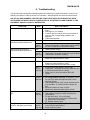
4. Troubleshooting
Your Groen kettle is designed to operate smoothly and efficiently if properly maintained. However, the
following are checks to make in the event of a problem. Wiring diagrams are inside the service panel.
USE OF ANY REPLACEMENT PARTS OTHER THAN THOSE SUPPLIED BY GROEN OR THEIR
AUTHORIZED DISTRIBUTORS CAN CAUSE INJURY TO THE OPERATOR AND DAMAGE TO THE
EQUIPMENT AND WILL VOID ALL WARRANTIES.
SYMPTOM
WHO
WHAT TO CHECK
Burners will not light.
User
a. Is main gas valve open (handle in line with gas
pipe)?
b. Gas supply to your building.
c. Is electric power turned on at the circuit breaker or
fuse box, and is power being supplied to the
appliance
d. Thermostat operation.
Kettle continues heating after it
reaches the desired temperature.
User
a. Thermostat dial setting.
Kettle stops heating before it
reaches the desired temperature.
User
Kettle heats slowly
User
a. Air in jacket - pressure/vacuum gauge (20 to 30
below zero when the kettle is cold?)
Safety valve pops.
User
a. Air in jacket - pressure/vacuum gauge (20 to 30
below zero when the kettle is cold?)
b. Whether kettle was being heated while empty.
Auth
b. Thermostat calibration.Y
Service
c. Thermostat operation. Thermostat should click when
Rep Only
the dial is rotated above and below a setting.Y
a. Thermostat dial setting.
Auth
b. Thermostat calibration. Y
Service
c. Thermostat. Thermostat should click when the dial is
Rep Only
rotated above and below a setting.Y
Auth
c.
Service
d.
Rep Only
e.
If high pressure limit switch is set too high. Y
Thermostat. Thermostat should click when the dial
is rotated above and below a setting. Y
Safety valve. If valve pops below 300 PSIG,
replace.Y
Auth
a. Thermostat: close the contacts if they are open Y
Service
b. AC voltage between terminals “1" and “GR.” If it is
Rep Only
not 230 Volt, check the high limit switch, which
should be closed. Y
c. That the high tension cable is firmly attached and in
good condition. If cracked or brittle, replace the
pilot.Y
e. Electrode ceramic for crack or break.Y
f. Replace the electronic spark ignition module.Y
Spark is present but the pilot will not Auth
a. That the gas valve is opening.Y
light.
Service
b. That pressure meets the control manufacturer’s
Rep Only
specifications.Y
c. For gas at the pilot. If it is not flowing:
(1) Check pilot gas line for kinks or obstructions.Y
(2) Clean orifice, if necessary.Y
(3) Replace the pilot valve.Y
Pilot lights, but main burner will not Auth
a. That the gas pressure meets the control
come on and spark does not stay
Service
manufacturer’s specifications.Y
on.
Rep Only b. Replace electric moduleY
System does not produce a spark
15
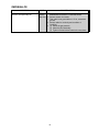
OM/SM-AH-CE
SYMPTOM
Pilot lights, but main burner will not
come on, the spark stays on.
WHO
WHAT TO CHECK
Auth
a. Sensor cable, to make certain that there are secure
Service
attachments to terminal “13" and the sensor.Y
Rep Only b. Sensor ceramic for cracks.Y
c. That cable is not grounded out. If it is, correct the
ground.Y
d. Sensor cable for continuity and condition of
insulation.Y
e. (1) Check the gas pressure.Y
(2) Clean the pilot Assembly.Y
(3) Tighten mechanical and electrical connections.Y
16
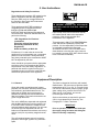
OM/SM-AH-CE
5. User Instructions
Regulations and Safety Precautions
These Appliances have been CE marked on the
basis of compliance with the Gas Appliance
Directive, EMC and Low Voltage Directive for
the Countries, Gas Types and Pressures as
stated on the Data Plate.
WARNING
TO PREVENT SHOCKS, ALL APPLIANCES
WHETHER GAS OR ELECTRIC, MUST BE
EARTHED.
These appliances MUST BE installed by a
competent person in compliance with the
INSTALLATION AND SERVICING
INSTRUCTIONS and National Regulations in
force at the time. Particular attention MUST be
paid to the following:
Upon receipt of the User's Instruction manual,
the installer should instruct the responsible
person(s) of the correct operation and
maintenance of the Appliance.
I.E.E. Regulations for Electrical
Installations
Electricity at Work Regulations
Gas Safety (Installation & Use)
Regulations
Health and Safety at Work Act
This equipment is ONLY FOR PROFESSIONAL
USE, and shall be operated by QUALIFIED
persons. It is the responsibility of the Supervisor
or equivalent to ensure that users wear
SUITABLE PROTECTIVE CLOTHING and to
draw attention to the fact that, some parts will,
by necessity, become VERY HOT and will cause
burns if touched accidentally.
Furthermore, if a need arises to convert the
appliance for use with another gas, a competent
person must be consulted. Those parts which
have been protected by the manufacturer MUST
NOT be adjusted by the User.
Users should be conversant with the appropriate
provisions of the Fire Precautions Act and the
requirements of the Gas Safety Regulations. In
particular the need for regular servicing by a
competent person to ensure the continued safe
and efficient performance of the Appliance.
5.1
Equipment Description
5.1.1 General
The kettle is charged at the factory with treated,
distilled water. The steam source provides kettle
temperatures of 65° C to 134° C. Controls for the
unit include a thermostat, pressure gauge, gauge
glass, safety valve, pressure limit control, low
water cut-off, on/off switch, and a multifunctional gas control valve.
Groen AH models are stainless steel, steamjacketed, floor mounted, stationary kettles with a
self-contained, gas heated steam source. The
kettle body is welded into one piece and is
sheathed in stainless steel and insulated with
fiber bat insulation. The interior and exterior are
given a bright buff finish.
Service connections are required for gas and
230-V, single phase 50-Hz electricity. See
Paragraph 3.4 - Water Treatment.
The unit is ASME shop inspected and registered
with the National Board for working pressure up
to 30 PSIG. Kettle controls are contained in an
enclosed stainless steel enclosure. The unit rests
on tubular legs with adjustable ball feet. AH
kettles come standard with stainless steel covers
and two inch (five cm) sanitary tangent draw-off
valve.
IMPORTANT
Prior to operation, clean out the kettle pan
thoroughly using hot water and detergent.
Rinse out and dry completely.
The self-contained steam source is heated by
propane or natural gas. Ignition is by electronic
spark.
17
OM/SM-AH-CE
The gas burners are protected by an
electronic flame failure device which
incorporates automatic ignition of the
burners and instant shut-off of the gas
supply to the burners should a gas supply
interruption occur.
WARNING
INSTALLATION OF THE UNIT MUST BE
DONE BY PERSONNEL QUALIFIED TO
WORK WITH ELECTRICITY, GAS AND
PLUMBING IN ACCORDANCE WITH ALL
APPLICABLE CODES.
Options available with listed models are:
1. Three inch (7.6 cm) tangent draw-off
valve. (Factory-installed option)
2. Basket inserts.
BEFORE
REPLACING
ANY
PARTS,
DISCONNECT THE UNIT FROM THE
ELECTRIC POWER SUPPLY AND CLOSE
THE MAIN GAS COCK. ALLOW FIVE
MINUTES FOR UNBURNED GAS TO VENT.
3. Water filler with swing spout and
bracket.
4. Kettle brush kit.
5.1.2
Operational and Maintenance Safety
TO PREVENT SHOCKS, ALL APPLIANCES
WHETHER GAS OR ELECTRIC, MUST BE
EARTHED.
CAUTION
BE SURE ALL OPERATORS READ,
UNDERSTAND AND FOLLOW OPERATING
INSTRUCTIONS, CAUTIONS AND SAFETY
INSTRUCTIONS IN THIS MANUAL.
5.2 Lighting and Operation
5.2.1
Initial Kettle Lighting and Operational
Readiness Check
require venting. (This will require a
service call).
After the AH Kettle has been installed according
to service and installation instructions, perform
initial start-up as a test to ensure that the unit is
operating correctly. Follow the steps below.
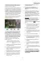
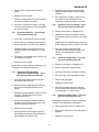
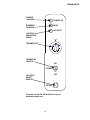
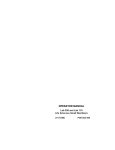
Refer to the picture for identification of AH
controls and indicators.
6. Switch the On/Off switch to the "On"
position. The "power on" neon will
illuminate.
7. Turn the thermostat dial to the required
setting.
1. Remove all literature and packing
material from the interior and exterior of
the unit.
8. After 10-15 seconds the burners should
light. The "burners on" neon will
illuminate.
2. Make sure gas and electricity supplies
are switched on.
9. In the event the burners do not light, or
go out as indicated by the illumination of
the lockout indicating neon, turn the unit
off. Wait approx 1 minute. Press lockout
reset switch and repeat steps (4) to (8).
3. Ensure that the kettle is filled with water
before lighting.
4. Check the water level in the jacket. The
level should be between the lines on the
gauge glass. If the level is low, the
jacket water level will be required to be
topped up. (This will require a service
call).
WARNING
AVOID CONTACT WITH THE FLUE.
SURFACES ARE VERY HOT AND WILL
CAUSE BURNS.
DO NOT OBSTRUCT FLUE EXHAUST
OPENING.
5. Check the pressure gauge. If the gauge
does not show sufficient vacuum (that is,
20 to 30 below zero), the jacket will
18
OM/SM-AH-CE
POWER
ON NEON
POWER ON
HEAT
BURNERS
ON NEON
LOCKOUT
LOCKOUT
INDICATING
NEON
THERMOSTAT
POWER ON
SWITCH
ON
POWER
OFF
LOCKOUT
RESET
SWITCH
RESET
Controls on the AH-CE model are easy to
understand and use.
19
OM/SM-AH-CE
5.2.2
To Shut Down Kettle
1. Low-water cutoff relay that will shut off
the gas supply to all burners until the
water level is corrected.
1. Turn the thermostat dial to the Off
position.
2. High pressure switch, set to open at
about 27 PSIG and shut down the
burners until jacket pressure is
decreased.
2. Switch the On/Off switch to the Off
position.
3. For a prolonged shut down follow steps
1 and 2, and turn the gas and electricity
supplies off.
5.2.3
3. Pop safety valve, which will release
steam if the jacket pressure exceeds 30
PSIG.
Filling the Kettle
See detailed Instructions on Page 8 pertaining to
Safety Valve installation and operation.
Prior to operation of the unit, clean out the kettle
pan thoroughly, using hot water and detergent.
When the kettle reaches the set temperature,
the thermostat switch opens, stopping the signal
to the gas control valve and causing the valve to
shut off all gas flow. When the kettle cools below
the set temperature, the thermostat switch
closes and starts another heating cycle. On-off
cycling continues and maintains the kettle at the
desired temperature.
Kettle Capacities:
Model
AH-20
AH-40
AH-60
AH-80
Capacity
75.7 Liters
151.4 Liters
227.1 Liters
302.8 Liters
5.2.6 To Empty Kettle
Note that these are maximum capacities. Groen
recommends that no more than 80% of the
maximum capacity be used during operation.
5.2.4
Turn the handle on the tangent draw off valve
anti-clockwise. After approximately 3½ turns the
valve handle can be pulled forward and full flow
achieved. To close the tangent draw off valve,
push the valve handle inward until the threads
on the valve stem engage. Turn the handle
clockwise until the valve is closed. Do not over
tighten the valve since over-tightening may
damage the valve seat.
Users Thermostat
The thermostat provides automatic control of the
Kettle Jacket temperature at selected settings to
a maximum of 134° C.
5.2.5
Sequence of Operation
HOT
SURFACES
SURFACE
The following "sequence of operation" outline is
provided to help the user understand the
functioning of the unit.
WARNING
WHEN EMPTYING THE KETTLE BE
CAREFUL TO KEEP HOT CONTENTS FROM
SPILLING. AVOID DIRECT SKIN CONTACT.
ENSURE PEOPLE ARE KEPT AWAY FROM
THE KETTLE WHEN EMPTYING IT.
When the operator sets the desired temperature
on the thermostat dial, the thermostat switch
closes and sends a signal which (1) starts the
spark and (2) opens the automatic valve for the
burners. The spark ignites the burner on low
flow. The flame completes a circuit at the
sensing probe and sends a signal that causes
the spark to shut off and the automatic valve to
open to full flow once a flame has been
detected. If a flame is not detected within 15
seconds the gas is automatically cut off and the
appliance is locked out. The unit can only be relit once the reset button has been pressed.
5.2.7 Power Failure
If power to the unit fails, do not attempt to
operate the appliance until the electricity supply
is reestablished.
When the power comes back on, follow the
steps in Paragraph 5.2.1 (Initial Kettle Lighting
and Operational Readiness Check.)
In addition to the lockout timer, safety features
include:
20
OM/SM-AH-CE
5.3 Cleaning and Maintenance
IMPORTANT
Disconnect the electricity supply before
any cleaning is undertaken. The
appliance must not be cleaned with a jet
of water, nor steam-cleaned.
5.3.1
Suggested Tools
1. Detergent and sanitizing agent, or a
combination cleaning - sanitizing
agent.
2. Long handled and short handled
kettle brushes.
5.3.2
Precautions
Before cleaning, shut off the burner by
turning the thermostat dial to "OFF". If water
or cleaning/sanitizing solution will be
sprayed, shut off all electric power to the
unit at a remote switch such as the circuit
breaker.
Use a brush, sponge, cloth, plastic or rubber
to remove materials stuck to the surface.
plastic or rubber scraper, or plastic wool
along with the detergent solution. To
minimize the effort required in washing,
let the detergent solution sit in the kettle
and soak into the residue, or briefly heat
the detergent solution.
WARNING
KEEP WATER AND SOLUTIONS OUT OF
CONTROLS. NEVER SPRAY OR HOSE
DOWN THE CONTROL CONSOLE.
5.3.3
Procedure
Do not use any abrasive materials or
metal implement that might scratch the
surface because scratches make the
surface hard to clean and provide places
for bacteria to grow. DO NOT use steel
wool, which may leave particles
imbedded in the surface and cause
eventual corrosion and pitting.
1. Clean all food contact surfaces as soon
as possible after use, preferably while
the kettle is still hot. If the unit is in
continuous use, thoroughly clean and
sanitize both interior and exterior at
least once every 12 hours.
2. Scrape and flush out large amounts of
food residues. Be careful not to scratch
the kettle with metal implements.
3. Prepare a solution of the detergent/
cleaning compound as instructed by the
supplier. Clean the unit thoroughly. A
cloth moistened with cleaning solution
may be used to clean controls, control
housings and electrical conduits.
4. As part of the daily cleaning program,
clean all external and internal surfaces
that may have been soiled. Remember
to check such parts as the underside of
the kettle and control housing.
Do not use metal implements or steel wool.
6.
5. To remove materials stuck to the
equipment, use a brush, sponge, cloth,
21
The exterior of the unit may be polished
with a recognized stainless steel cleaner
or with water and detergent.
OM/SM-AH-CE
7. When equipment needs to be sanitized,
use a solution equivalent to one that
supplies 200 parts per million available
chlorine. Obtain advice on the best
sanitizing agent from your products
supplier. Follow the supplier’s
instructions and apply the agent after the
unit has been cleaned and drained.
Thoroughly rinse off the sanitizing agent.
5.3.4 Safety Precautions
A stopcock will be fitted in the gas pipe
supplying the appliance. The user must be
familiar with its location and operation so that it
may be turned off in an emergency. If there is a
smell of gas, turn off the gas, ventilate the area
and call the gas supplier. Do not search for gas
leaks with naked flames.
5.3.5 Service/Periodic Maintenance
CAUTION
NEVER LEAVE A CHLORINE SANITIZING
AGENT IN CONTACT WITH STAINLESS
STEEL SURFACES LONGER THAN 30
MINUTES. LONGER CONTACT CAUSES
CORROSION.
A Maintenance and Service Log is included in
this manual. Each time maintenance is
performed on your Groen equipment, enter the
date on which it was done, what was done, and
who did it. Keep the manual, its warranty and the
log near the unit. Periodic inspection can
minimize equipment down time and increase the
efficiency of operation. The following points
should be checked regularly.
8. It is recommended that the unit be
sanitized before use.
9.
If there is difficulty removing mineral
deposits or a film left by hard water or
food residue, clean the kettle thoroughly.
Then use a de-liming agent, such as
Groen Delimer Descaler (P/N 114800) or
Lime-Away from EcoLab, Inc, in
accordance with the manufacturer's
directions. Rinse and drain the unit
before further use.
10. If especially difficult cleaning problems
persist, contact your cleaning product
supplier for assistance.
22
1.
The pressure/vacuum gauge should
show a vacuum of 20 to 30 inches when
the kettle is cold. If it does not, the unit
requires servicing.
2.
The jacket water level should be
between the marks on the gauge glass.
If it is not, the unit requires servicing.
3.
Keep electrical wiring in good condition.
OM/SM-AH-CE
23
OM/SM-AH-CE
Parts Lists
24
OM/SM-AH-CE
Parts Lists
Key
7
9
9
10
10
11*
11*
11*
11*
11*
11*
11*
11*
11*
11*
11*
11*
11*
11*
11*
11*
11*
11*
13
13
17
17
17
17
21
22
23
32
33
34
37
38
39
40
41
42
Description
Part No.
Key
Description
Foot, Adjustable Bullet
013275
43 Switch Push Button (momentary)
Bracket Burner Support, AH/1-60, -80 000388
44 Thermostat
Bracket Burner Support, AH/1-20, -40 000336
45 Thermostat Adapter (shaft bushing)
Bracket Burner Head AH/1-60, -80
000389
46 Screw, Rnd Hd slotted 8-32 x 3/8 lg
Bracket Burner Head AH/1-20, -40
000337
47 Knob, Thermostat
Burner Assy. (Natural G20) (80 60)
117730A
48 Electrical Panel Assembly
Burner Assy. (Natural G20) (40)
117795A
50 Label, Wiring Diagram
Burner Assy. (Natural G20) (20)
117731A
Wire Harness **
Burner Assy. (Natural G25) (80 60)
117730C
54 Water Level Electrode
Burner Assy. (Natural G25) (40)
117795C
56 Boot Electrode
Burner Assy. (Natural G25) (20)
117731C
57 Pressure Switch, High Limit
Burner Assy. (Propane G31) (80, 60) 117730B
58 TDO Kit replacement parts
Burner Assy. (Propane G31) (40)
117795B
58a Valve Stem
Burner Assy. (Propane G31) (20)
117731B
58b Bonnet
Burner Injector (Natural G20) (80 60) 000399
58c O-Ring
Burner Injector (Natural G20) (40)
000280
58d Hex Nut
Burner Injector (Natural G20) (20)
000480
58e Handle
Burner Injector (Natural G25) (80 60) 127386
58f Wing Nut
Burner Injector (Natural G25) (40)
127385
59 Bracket, Faucet Mounting
Burner Injector (Natural G25) (20)
127384
61 Data Plate, CE Mark Kettles
Burner Injector (PropaneG31) (80 60) 000403
62 Nameplate, Groen, Large
Burner Injector (Propane G31) (40)
000281
68 Cover Assy w/Power Aid AH/1-80**
Burner Injector (Propane G31) (20)
000281
68 Cover Assy w/Power Aid AH/1-60**
Radiation Shield Assy, AH/1-60, -80
000445
68 Cover Assy w/Power Aid AH/1-40**
Radiation Shield Assy, AH/1-20, -40
000448
68 Cover Assy w/Power Aid AH/1-20**
Cover Panel, AH/1-80
117721
Users Manual**
Cover Panel, AH/1-60
117720
71 Assembly, Equipotential Terminal
Cover Panel, AH/1-40
117719
73 Wire Assembly, Supplementary
Cover Panel, AH/1-20
117718
74 Wire Assembly, Flame Rod
Insulator, Pilot Burner Access
008201
79 Adapter 1/2” BSPT (M) x1/2"NPT (F)
Door, Pilot Burner Access
004035
80 Pilot Ignition Controller
Hinge, Pilot Door
004114
81 Liquid Level Control Relay
Safety Valve & Water Fill Assembly
097010
82 Liquid Level Control Relay Base
Plate with Chain Assembly
008332
83 Terminal Block
Water Gauge Fitting
004071
84 Fuse (Three Amp)
Sight tube, 5/8” Diameter x 4-3/4” lg
008742
85 Fuse Block
Pressure Gauge 2-1/2“dia (dual scale) 084208
86 Pilot Burner & Orifice Assy (Natural)
Overlay, Panel
117716+
87 Pilot Burner & Orifice Assy (Propane)
Switch, Toggle, DPST
122004
88 Pilot Burner Mounting Bracket
Light Indicator Red, 240V
116381
89 Water Treatment Kit
Light Indicator, Amber 240V
116382
*NOTE: See Para 1.10 (Page 6) for permissible conversions.
** Not Shown
25
Part No.
122003
012313
107172
009697
122000
117732
113077
117727
074665
010390
108559
100573
009048
009047
009034
009354
009029
009028
009054
114504
055450
047694
049884
067417
047695
122039
122021
122013
122034
116392
113060
117737
117738
003119
079965
077854
117704
117705
004425
110324
OM/SM-AH-CE
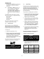
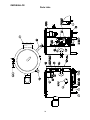
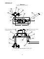
Parts Lists
Keyed to Parts Listing on Page 29
16
11
30E
8
INSTALL WITH 1/2"BSPT THREADS
TOWARD GAS VALVE
8
8
INSTALL WITH 1/2"BSPT THREADS
TOWARD GAS VALVE
13
1
9
6
10
7
2
3
18
4
1
12
14
Gas Valve and Piping Assembly, AH/1-20
26
5
OM/SM-AH-CE
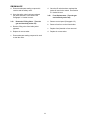
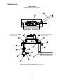
Parts List
Keyed to Parts Listing on Page 29
16
13
11
B
30E
12
18
8
3
INSTALL WITH 1/2"BSPT THREADS
TOWARD GAS VALVE
8
8
INSTALL WITH 1/2"BSPT THREADS
TOWARD GAS VALVE
1
1
9
C
5
10
7
2
1
4
14
Gas Valve and Piping Assembly, AH/1-40
27
5
OM/SM-AH-CE
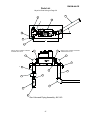
Parts List
Keyed to Parts Listing on Page 29
11
11
5
10
17
3
16
14
15
B
4
30E
6
8
INSTALL WITH 1/2"BSPT THREAD
TOWARDS GAS VALVE
9
9
B
1
INSTALL WITH 1/2"BSPT THREAD
TOWARDS GAS VALVE
1
12
7
8
13
2
1
Gas Valve and Piping Assembly, AH/1-60, 1-80
28
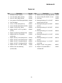
OM/SM-AH-CE
Parts List
Key
Description
Part No.
Key
Description
Part No.
1
90º Elbow 1/2” NPT (black)
008747
9
Bracket, Gas Valve Mounting (AH-20)
122080
2
Union 3/8” NPT (black) (AH-20)
005686
10
Screw, Phillips Pan Hd M5 x 10 mm
116388
2
Union 1/2” NPT (black) (AH-40
004186
11
Gas Valve
114505
2
Union elbow 1/2”NPT(black)(AH-60 80) 005495
12
Bushing Reducing 1/2” x 1/8" NPT
088290
3
Gas Test Nipple
117051
4
Cross, 1/2” NPT (black) (AH-20)
060241
4
Cross, 3/8” NPT (black) (AH-40,60,80)
097587
5
Nipple 1/2” NPTx4"Lg. (black)
005554
6
Nipple 3/8” NPT x 4-1/2” Lg. (black)
005635
(AH-20)
(black) (AH-40, 60, 80)
12
Nipple 1/2” NPTx4”Lg.(black)(AH-40)
005554
6
Nipple1/2”NPTx5-1/2”Lg.(black)
010234
049943
(AH-20)
13
Bushing Reducing 1/2”x 3/8" NPT
007442
(AH-40)
13
6
Bushing Reducing 3/8”x 1/8" NPT
Bushing Reducing 1/2” x 1/8" NPT
088290
(AH-60,80)
14
(AH-60, 80)
Bushing Reducing 3/8” x 1/4" NPT
013296
(AH-20)
7
Nipple, 3/8” NPT, close (black) AH-20
007439
7
Nipple, 1/2” NPT, close (black) AH-40
008877
7
Nipple, 1/2” NPT, 3"Lg (black) AH-60
005553
7
Nipple, 1/2” NPT, 4"Lg (black) AH-80
005554
8
Nipple 1/2" NPT x 1/2” BSPT (brass)
116394
16
Nipple 1/2” NPT x 8 Lg. (black)
005557
9
Bracket, Gas Valve Mounting
117717
19
Adaptor 1/8” Female BSPP x
122087
(AH-40,60,80)
14
Bushing Reducing 1/2” x 1/4" NPT
(AH-40)
14
Bushing Reducing 1” x 1-1/2” NPT
002647
(AH-60,80)
1/8” Male NPT
29
008739
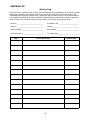
OM/SM-AH-CE
Service Log
The Groen Steam Jacketed Kettle you have just purchased has been handcrafted from the finest materials,
meticulously inspected, and carefully tested to ensure that you receive the best possible product. With
reasonable care and periodic maintenance, it will provide years of faithful service. It is recommended that
you establish a timetable for periodic maintenance with an Authorized Groen Service Agency. Space has
been provided in the manual for a Maintenance & Service Log. Keep it up-to-date and on file.
Model m _________________________________
Purchased From _________________________
Serial m _________________________________
Location ________________________________
Date Purchased ___________________________
Date Installed ___________________________
Purchase Order m _________________________
For Service Call __________________________
Date
Service Performed
30
Performed By
Limited Warranty To Commercial Purchasers*
(for Areas Outside of the U.S. and Canada)
Groen Foodservice Equipment ("Groen Equipment") has been skillfully manufactured, carefully inspected
and packaged to meet rigid standards of excellence. Groen warrants its Equipment to be free from defects
in material and workmanship for ( 12) twelve months from date of installation or ( 18) eighteen months from
date of shipment with the following conditions and subject to the following limitations.
I.
This parts warranty is limited to Groen Equipment sold to the original commercial purchaser/users
(but not original equipment manufacturers), at its original place of installation, in areas outside the
U.S. and Canada.
II.
Damage during shipment is to be reported to the carrier, is not covered under this warranty, and is
the sole responsibility of the purchaser/user.
III. Groen, or an authorized service representative, will repair or replace parts, at Groen's sole election,
for any Groen Equipment, including but not limited to, draw-off valves, safety valves, gas and
electric components, found to be defective during the warranty period.
IV. This warranty does not cover boiler maintenance, calibration, or periodic adjustments as specified in
operating instructions or manuals, and consumable parts such as scraper blades, gaskets, packing,
etc., or labor costs incurred for removal of adjacent equipment or objects to gain access to Groen
Equipment. This warranty does not cover defects caused by improper installation, abuse, careless
operation, or improper maintenance of equipment. This warranty does not cover damage caused by
poor water quality or improper boiler maintenance.
v.
THIS WARRANTY IS EXCLUSIVE AND IS IN LIEU OF ALL OTHER WARRANTIES, EXPRESSED
OR IMPLIED, INCLUDING ANY IMPLIED WARRANTY OF MERCHANTABILITY OR FITNESS
FOR A PARTICULAR PURPOSE, EACH OF WHICH IS HEREBY EXPRESSLY DISCLAIMED.
THE REMEDIES DESCRIBED ABOVE ARE EXCLUSIVE AND IN NO EVENT SHALL GROEN BE
LIABLE FOR SPECIAL, CONSEQUENTIAL OR INCIDENTAL DAMAGES FOR THE BREACH OR
DELAY IN PERFORMANCE OF THIS WARRANTY.
VI. Groen Equipment is for commercial use only. If sold as a component of another (O.E.M.)
manufacturer's equipment or if used as a consumer product, such Equipment is sold AS IS and
without any warranty.
* (Covers All Food Service Equipment Ordered After October 1,1995)
1055 Mendell Davis Drive
Jackson, Mississippi 39272
Telephone 601 373-3903
FAX 601 373-9587
OM/SM-AH-CE
Part Number 128416
Revised 4/99