1
FCB VIPER
Service Manual
Release Date: October 28, 2008
Publication Number: 621260373SER
Revision Date: July 13, 2009
Revision: D
Visit the IMI Cornelius web site at www.cornelius.com for all your Literature needs.
CONTACT INFORMATION
The products, technical information, and instructions contained in this manual are subject to change without notice. These instructions are not intended to cover all details or variations of the equipment, nor to
provide for every possible contingency in the installation, operation or maintenance of this equipment.
This manual assumes that the person(s) working on the equipment have been trained and are skilled in
working with electrical, plumbing, pneumatic, and mechanical equipment. Appropriate safety precautions
should be followed and all local safety and construction requirements should be met.
To inquire about current revisions of this and other documentation, or for assistance with any Cornelius
product contact:
www.cornelius.com
800-238-3600
This document contains proprietary information and it may not be reproduced in any way without permission from Cornelius.
Printed in U.S.A.
Copyright © 2008-2009, All Rights Reserved, IMI Cornelius Inc.
Introduction . . . . . . . . . . . . . . . . . . . . . . . . . . . . . . . . . . . . . . . . . . . . . . . . . . . . . . . . . . . . . . . . . . . . . 1
Manual Overview . . . . . . . . . . . . . . . . . . . . . . . . . . . . . . . . . . . . . . . . . . . . . . . . . . . . . . . . . . . . . . . 1
Safety . . . . . . . . . . . . . . . . . . . . . . . . . . . . . . . . . . . . . . . . . . . . . . . . . . . . . . . . . . . . . . . . . . . . . . . . . .
Safety Instructions . . . . . . . . . . . . . . . . . . . . . . . . . . . . . . . . . . . . . . . . . . . . . . . . . . . . . . . . . . . . . .
Read and Follow ALL Safety Instructions . . . . . . . . . . . . . . . . . . . . . . . . . . . . . . . . . . . . . . . . .
Safety Overview . . . . . . . . . . . . . . . . . . . . . . . . . . . . . . . . . . . . . . . . . . . . . . . . . . . . . . . . . .
Recognition . . . . . . . . . . . . . . . . . . . . . . . . . . . . . . . . . . . . . . . . . . . . . . . . . . . . . . . . . . . . .
Different Types of Alerts. . . . . . . . . . . . . . . . . . . . . . . . . . . . . . . . . . . . . . . . . . . . . . . . . . . . . . .
Danger . . . . . . . . . . . . . . . . . . . . . . . . . . . . . . . . . . . . . . . . . . . . . . . . . . . . . . . . . . . . . . . . .
Warning . . . . . . . . . . . . . . . . . . . . . . . . . . . . . . . . . . . . . . . . . . . . . . . . . . . . . . . . . . . . . . . .
Caution. . . . . . . . . . . . . . . . . . . . . . . . . . . . . . . . . . . . . . . . . . . . . . . . . . . . . . . . . . . . . . . . .
Safety Tips . . . . . . . . . . . . . . . . . . . . . . . . . . . . . . . . . . . . . . . . . . . . . . . . . . . . . . . . . . . . . . . . . . . .
Qualified Service Personnel. . . . . . . . . . . . . . . . . . . . . . . . . . . . . . . . . . . . . . . . . . . . . . . . . . . . . . .
CO2 (Carbon Dioxide) Warning . . . . . . . . . . . . . . . . . . . . . . . . . . . . . . . . . . . . . . . . . . . . . . . . . . . .
Shipping And Storage . . . . . . . . . . . . . . . . . . . . . . . . . . . . . . . . . . . . . . . . . . . . . . . . . . . . . . . . . . .
Mounting on a Counter . . . . . . . . . . . . . . . . . . . . . . . . . . . . . . . . . . . . . . . . . . . . . . . . . . . . . . . . . .
Dispensed Product Conditions. . . . . . . . . . . . . . . . . . . . . . . . . . . . . . . . . . . . . . . . . . . . . . . . . . . . .
Overrun, as Applied to Carbonated Beverages . . . . . . . . . . . . . . . . . . . . . . . . . . . . . . . . . . . . .
Overrun Definition . . . . . . . . . . . . . . . . . . . . . . . . . . . . . . . . . . . . . . . . . . . . . . . . . . . . . . . .
Overrun is a Variable . . . . . . . . . . . . . . . . . . . . . . . . . . . . . . . . . . . . . . . . . . . . . . . . . . . . . .
Specific Product Ingredients Affect Overrun . . . . . . . . . . . . . . . . . . . . . . . . . . . . . . . . . . . .
BRIX Affects Overrun . . . . . . . . . . . . . . . . . . . . . . . . . . . . . . . . . . . . . . . . . . . . . . . . . . . . . .
Low Dispensing Volume Affects Overrun. . . . . . . . . . . . . . . . . . . . . . . . . . . . . . . . . . . . . . .
Carbonation Level in Liquid Product Affects Overrun . . . . . . . . . . . . . . . . . . . . . . . . . . . . .
Freezing Affects Overrun . . . . . . . . . . . . . . . . . . . . . . . . . . . . . . . . . . . . . . . . . . . . . . . . . . .
2
2
2
2
2
2
2
2
2
2
3
3
3
3
4
4
4
4
4
4
5
5
5
System Overview . . . . . . . . . . . . . . . . . . . . . . . . . . . . . . . . . . . . . . . . . . . . . . . . . . . . . . . . . . . . . . . . . 6
Introduction . . . . . . . . . . . . . . . . . . . . . . . . . . . . . . . . . . . . . . . . . . . . . . . . . . . . . . . . . . . . . . . . . . . 6
Theory of Operation . . . . . . . . . . . . . . . . . . . . . . . . . . . . . . . . . . . . . . . . . . . . . . . . . . . . . . . . . . . . . 7
CO2 System. . . . . . . . . . . . . . . . . . . . . . . . . . . . . . . . . . . . . . . . . . . . . . . . . . . . . . . . . . . . . . . 13
Water System. . . . . . . . . . . . . . . . . . . . . . . . . . . . . . . . . . . . . . . . . . . . . . . . . . . . . . . . . . . . . . 18
Syrup System. . . . . . . . . . . . . . . . . . . . . . . . . . . . . . . . . . . . . . . . . . . . . . . . . . . . . . . . . . . . . . 18
Control Panel . . . . . . . . . . . . . . . . . . . . . . . . . . . . . . . . . . . . . . . . . . . . . . . . . . . . . . . . . . . . . . . . . 18
Introduction . . . . . . . . . . . . . . . . . . . . . . . . . . . . . . . . . . . . . . . . . . . . . . . . . . . . . . . . . . . . . . . 18
Control Panel Display. . . . . . . . . . . . . . . . . . . . . . . . . . . . . . . . . . . . . . . . . . . . . . . . . . . . . 19
Control Panel Buttons . . . . . . . . . . . . . . . . . . . . . . . . . . . . . . . . . . . . . . . . . . . . . . . . . . . . 19
Control Panel Menu Descriptions . . . . . . . . . . . . . . . . . . . . . . . . . . . . . . . . . . . . . . . . . . . . . . . . . 21
System Menus . . . . . . . . . . . . . . . . . . . . . . . . . . . . . . . . . . . . . . . . . . . . . . . . . . . . . . . . . . . . . 21
Main Menu . . . . . . . . . . . . . . . . . . . . . . . . . . . . . . . . . . . . . . . . . . . . . . . . . . . . . . . . . . . . . . . . 21
Unit Data Menu . . . . . . . . . . . . . . . . . . . . . . . . . . . . . . . . . . . . . . . . . . . . . . . . . . . . . . . . . 22
Error Status Menu . . . . . . . . . . . . . . . . . . . . . . . . . . . . . . . . . . . . . . . . . . . . . . . . . . . . . . . 23
Error Log Menu . . . . . . . . . . . . . . . . . . . . . . . . . . . . . . . . . . . . . . . . . . . . . . . . . . . . . . . . . 25
Setup Menu . . . . . . . . . . . . . . . . . . . . . . . . . . . . . . . . . . . . . . . . . . . . . . . . . . . . . . . . . . . . . . . 25
Clock Setup Menu . . . . . . . . . . . . . . . . . . . . . . . . . . . . . . . . . . . . . . . . . . . . . . . . . . . . . . . 26
Setting the Clock . . . . . . . . . . . . . . . . . . . . . . . . . . . . . . . . . . . . . . . . . . . . . . . . . . . . . 26
Setting Daylight Savings Time . . . . . . . . . . . . . . . . . . . . . . . . . . . . . . . . . . . . . . . . . . . 27
Events Setup Menu . . . . . . . . . . . . . . . . . . . . . . . . . . . . . . . . . . . . . . . . . . . . . . . . . . . . . . 28
Setting Events . . . . . . . . . . . . . . . . . . . . . . . . . . . . . . . . . . . . . . . . . . . . . . . . . . . . . . . . . . 29
Setting the Sleep and Wakeup Times . . . . . . . . . . . . . . . . . . . . . . . . . . . . . . . . . . . . . . . . 29
Setting Defrost Lockout . . . . . . . . . . . . . . . . . . . . . . . . . . . . . . . . . . . . . . . . . . . . . . . . 30
Viscosity Setup Menu. . . . . . . . . . . . . . . . . . . . . . . . . . . . . . . . . . . . . . . . . . . . . . . . . . . . . 31
Options Setup Menu . . . . . . . . . . . . . . . . . . . . . . . . . . . . . . . . . . . . . . . . . . . . . . . . . . . . .
Setting the Temperature Format . . . . . . . . . . . . . . . . . . . . . . . . . . . . . . . . . . . . . . . . .
Setting the Date Format. . . . . . . . . . . . . . . . . . . . . . . . . . . . . . . . . . . . . . . . . . . . . . . .
Setting the Time Format . . . . . . . . . . . . . . . . . . . . . . . . . . . . . . . . . . . . . . . . . . . . . . .
Setting the POS Lighting . . . . . . . . . . . . . . . . . . . . . . . . . . . . . . . . . . . . . . . . . . . . . . .
Setting the Type of Syrup . . . . . . . . . . . . . . . . . . . . . . . . . . . . . . . . . . . . . . . . . . . . . .
Maintenance Menu . . . . . . . . . . . . . . . . . . . . . . . . . . . . . . . . . . . . . . . . . . . . . . . . . . . . . . . . .
Barrel Maintenance Menu . . . . . . . . . . . . . . . . . . . . . . . . . . . . . . . . . . . . . . . . . . . . . . . . .
Purging a Barrel. . . . . . . . . . . . . . . . . . . . . . . . . . . . . . . . . . . . . . . . . . . . . . . . . . . . . .
Filling a Barrel . . . . . . . . . . . . . . . . . . . . . . . . . . . . . . . . . . . . . . . . . . . . . . . . . . . . . . .
Run the Barrel Motor . . . . . . . . . . . . . . . . . . . . . . . . . . . . . . . . . . . . . . . . . . . . . . . . . .
Rinsing a Barrel . . . . . . . . . . . . . . . . . . . . . . . . . . . . . . . . . . . . . . . . . . . . . . . . . . . . . .
Manual Diagnostic Menu . . . . . . . . . . . . . . . . . . . . . . . . . . . . . . . . . . . . . . . . . . . . . . . . . .
Totals Menu . . . . . . . . . . . . . . . . . . . . . . . . . . . . . . . . . . . . . . . . . . . . . . . . . . . . . . . . . . . .
BRIX Setup Menu . . . . . . . . . . . . . . . . . . . . . . . . . . . . . . . . . . . . . . . . . . . . . . . . . . . . . . .
Motor Setup Menu . . . . . . . . . . . . . . . . . . . . . . . . . . . . . . . . . . . . . . . . . . . . . . . . . . . . . . .
Calibrating a Motor . . . . . . . . . . . . . . . . . . . . . . . . . . . . . . . . . . . . . . . . . . . . . . . . . . .
System Menu. . . . . . . . . . . . . . . . . . . . . . . . . . . . . . . . . . . . . . . . . . . . . . . . . . . . . . . . . . .
Security . . . . . . . . . . . . . . . . . . . . . . . . . . . . . . . . . . . . . . . . . . . . . . . . . . . . . . . . . . . . . . .
Pressure Sensors . . . . . . . . . . . . . . . . . . . . . . . . . . . . . . . . . . . . . . . . . . . . . . . . . . . . . . .
31
32
32
32
32
33
33
33
34
34
35
35
35
36
37
39
40
41
42
42
Operation . . . . . . . . . . . . . . . . . . . . . . . . . . . . . . . . . . . . . . . . . . . . . . . . . . . . . . . . . . . . . . . . . . . . . .
Maintaining Product Quality . . . . . . . . . . . . . . . . . . . . . . . . . . . . . . . . . . . . . . . . . . . . . . . . . . . . .
Dispensed Product Throughput. . . . . . . . . . . . . . . . . . . . . . . . . . . . . . . . . . . . . . . . . . . . . . . .
Programmed Defrost Scheduling . . . . . . . . . . . . . . . . . . . . . . . . . . . . . . . . . . . . . . . . . . . . . .
Sleep Mode Recommendations . . . . . . . . . . . . . . . . . . . . . . . . . . . . . . . . . . . . . . . . . . . .
Viscosity Setting . . . . . . . . . . . . . . . . . . . . . . . . . . . . . . . . . . . . . . . . . . . . . . . . . . . . . . . . . . .
Starting the Unit. . . . . . . . . . . . . . . . . . . . . . . . . . . . . . . . . . . . . . . . . . . . . . . . . . . . . . . . . . . . . . .
44
44
44
45
45
45
45
Preventative Maintenance . . . . . . . . . . . . . . . . . . . . . . . . . . . . . . . . . . . . . . . . . . . . . . . . . . . . . . . .
Summary . . . . . . . . . . . . . . . . . . . . . . . . . . . . . . . . . . . . . . . . . . . . . . . . . . . . . . . . . . . . . . . . . . . .
Monthly Maintenance . . . . . . . . . . . . . . . . . . . . . . . . . . . . . . . . . . . . . . . . . . . . . . . . . . . . . . . . . .
Cleaning Air Filter . . . . . . . . . . . . . . . . . . . . . . . . . . . . . . . . . . . . . . . . . . . . . . . . . . . . . . . . . .
Semi-Annual Maintenance . . . . . . . . . . . . . . . . . . . . . . . . . . . . . . . . . . . . . . . . . . . . . . . . . . . . . .
Inspecting and Replacing Scraper Blades. . . . . . . . . . . . . . . . . . . . . . . . . . . . . . . . . . . . . . . .
Cleaning the Syrup Connections . . . . . . . . . . . . . . . . . . . . . . . . . . . . . . . . . . . . . . . . . . . . . . .
Servicing Motorman Dispensing Valves . . . . . . . . . . . . . . . . . . . . . . . . . . . . . . . . . . . . . . . . .
Sanitizing the System . . . . . . . . . . . . . . . . . . . . . . . . . . . . . . . . . . . . . . . . . . . . . . . . . . . . . . .
Emptying a Barrel . . . . . . . . . . . . . . . . . . . . . . . . . . . . . . . . . . . . . . . . . . . . . . . . . . . . . . .
Flushing the System of Syrup . . . . . . . . . . . . . . . . . . . . . . . . . . . . . . . . . . . . . . . . . . .
Sanitizing the Barrel . . . . . . . . . . . . . . . . . . . . . . . . . . . . . . . . . . . . . . . . . . . . . . . . . . . . .
Flushing the System . . . . . . . . . . . . . . . . . . . . . . . . . . . . . . . . . . . . . . . . . . . . . . . . . . . . .
Cleaning the Water Filter. . . . . . . . . . . . . . . . . . . . . . . . . . . . . . . . . . . . . . . . . . . . . . . . . . . . .
47
47
48
48
49
49
49
50
51
52
52
53
53
54
Component Replacement . . . . . . . . . . . . . . . . . . . . . . . . . . . . . . . . . . . . . . . . . . . . . . . . . . . . . . . . .
Barrel Motor Seal Replacement . . . . . . . . . . . . . . . . . . . . . . . . . . . . . . . . . . . . . . . . . . . . . . . . . .
Removing the Existing Seal. . . . . . . . . . . . . . . . . . . . . . . . . . . . . . . . . . . . . . . . . . . . . . . . . . .
Installing a New Seal . . . . . . . . . . . . . . . . . . . . . . . . . . . . . . . . . . . . . . . . . . . . . . . . . . . . . . . .
Motor Seal Leak Test . . . . . . . . . . . . . . . . . . . . . . . . . . . . . . . . . . . . . . . . . . . . . . . . . . . . . . .
Barrel Motor Replacement . . . . . . . . . . . . . . . . . . . . . . . . . . . . . . . . . . . . . . . . . . . . . . . . . . . . . .
Motor Run Capacitor Replacement . . . . . . . . . . . . . . . . . . . . . . . . . . . . . . . . . . . . . . . . . . . . . . . .
Water Pump Replacement . . . . . . . . . . . . . . . . . . . . . . . . . . . . . . . . . . . . . . . . . . . . . . . . . . . . . .
56
56
56
57
58
58
59
60
CO2 Shutoff Solenoid Replacement . . . . . . . . . . . . . . . . . . . . . . . . . . . . . . . . . . . . . . . . . . . . . . .
Syrup and Water Shutoff Solenoid Replacement . . . . . . . . . . . . . . . . . . . . . . . . . . . . . . . . . . . . .
CO2 Regulator Replacement. . . . . . . . . . . . . . . . . . . . . . . . . . . . . . . . . . . . . . . . . . . . . . . . . . . . .
Condenser Fan Motor Replacement . . . . . . . . . . . . . . . . . . . . . . . . . . . . . . . . . . . . . . . . . . . . . . .
Compressor Replacement . . . . . . . . . . . . . . . . . . . . . . . . . . . . . . . . . . . . . . . . . . . . . . . . . . . . . . .
Hot Gas Solenoid Replacement. . . . . . . . . . . . . . . . . . . . . . . . . . . . . . . . . . . . . . . . . . . . . . . . . . .
Liquid Line Solenoid Replacement . . . . . . . . . . . . . . . . . . . . . . . . . . . . . . . . . . . . . . . . . . . . . . . .
Syrup Pressure Switch Replacement . . . . . . . . . . . . . . . . . . . . . . . . . . . . . . . . . . . . . . . . . . . . . .
Water Pressure Switch Replacement . . . . . . . . . . . . . . . . . . . . . . . . . . . . . . . . . . . . . . . . . . . . . .
Display Board Replacement . . . . . . . . . . . . . . . . . . . . . . . . . . . . . . . . . . . . . . . . . . . . . . . . . . . . .
Control Board Replacement. . . . . . . . . . . . . . . . . . . . . . . . . . . . . . . . . . . . . . . . . . . . . . . . . . . . . .
Backward/Forward Compatibility with Older Software Versions . . . . . . . . . . . . . . . . . . . . . . .
Motor Board Replacement . . . . . . . . . . . . . . . . . . . . . . . . . . . . . . . . . . . . . . . . . . . . . . . . . . . . . . .
61
62
63
64
64
65
66
67
67
68
69
70
70
Troubleshooting. . . . . . . . . . . . . . . . . . . . . . . . . . . . . . . . . . . . . . . . . . . . . . . . . . . . . . . . . . . . . . . . . 72
Troubleshooting the System . . . . . . . . . . . . . . . . . . . . . . . . . . . . . . . . . . . . . . . . . . . . . . . . . . . . . 72
Troubleshooting Product Not Cold . . . . . . . . . . . . . . . . . . . . . . . . . . . . . . . . . . . . . . . . . . . . . . 73
Viper Service Manual
INTRODUCTION
MANUAL OVERVIEW
The organization of this manual allows the user to scan quickly to the subject of
interest along the left side of a page and to read the detail about the subject or
procedure on the right side of the page. The manual provides the detail needed
for newcomers to the industry while allowing experienced technicians to skip
over the details and move quickly through the material.
This manual is designed as a guide to the technician in maintaining and
servicing the Viper system. The Viper system is simple in design and has built-in
features and diagnostic controls to help the service technician quickly and
accurately service the machine.
The unit consists of multiple freeze barrels that each contain an internal beater
driven by a rear mounted electric motor, a refrigeration system, timer-controlled,
automatic hot gas defrost system and interconnecting tubing and controls
required to dispense the product.
Some of the system features and functions are listed below:
• Simple User Interface LCD Display
• Real Time Clock
• Incoming Line Voltage Sensing
• Pressure Sensing of Incoming Water, Syrup and CO2
• System Error Handling
• Error Log
• Viscosity Control
© 2008-2009, IMI Cornelius Inc.
-1-
Publication Number: 621260373SER
Viper Service Manual
SAFETY
SAFETY INSTRUCTIONS
Read and Follow ALL Safety Instructions
Safety Overview
Read and follow ALL SAFETY INSTRUCTIONS in this manual and any warning/
caution labels on the machine (decals, labels or laminated cards).
Read and understand ALL applicable OSHA (Occupational Safety and Health
Administration) safety regulations before operating this machine.
Recognition
Recognize Safety Alerts
This is the safety alert symbol. When you see it in this manual or on the
machine, be alert to the potential of personal injury or damage to the machine.
Different Types of Alerts
Danger
Danger - Indicates an immediate hazardous situation which if not avoided
WILL result in serious injury, death or equipment damage.
Warning
WARNING - Indicates a potentially hazardous situation which, if not
avoided, COULD result in serious injury, death, or equipment damage.
Caution
CAUTION - Indicates a potentially hazardous situation which, if not
avoided, MAY result in minor or moderate injury or equipment damage.
SAFETY TIPS
Carefully read all safety messages in this manual and safety signs on the
machine.
Keep safety signs in good condition and replace missing or damaged items.
Do not let anyone operate the machine without proper training. This appliance is
not intended for use by very young children or infirm persons without
supervision. Young children should be supervised to ensure that they do not
play with the appliance.
Publication Number: 621260373SER
-2-
© 2008-2009, IMI Cornelius Inc.
Viper Service Manual
Keep your machine in proper working condition and do not allow unauthorized
modifications to the machine.
QUALIFIED SERVICE PERSONNEL
CAUTION - Only trained and certified electrical, plumbing and refrigeration
technicians should service this unit. ALL WIRING AND PLUMBING MUST
CONFORM TO NATIONAL AND LOCAL CODES.
CO2 (CARBON DIOXIDE) WARNING
WARNING - CO2 Displaces Oxygen. Strict Attention must be observed in
the prevention of CO2 gas leaks in the entire CO2 and soft drink system. If a CO2
gas leak is suspected, particularly in a small area, immediately ventilate the
contaminated area before attempting to repair the leak. Personnel exposed to
high concentration of CO2 gas will experience tremors which are followed rapidly
by loss of consciousness and death.
SHIPPING AND STORAGE
CAUTION - Before shipping, storing, or relocating the Unit, syrup systems
must be sanitized and all sanitizing solution must be purged from the syrup
systems. All liquids, after sanitizing, must be purged from the unit. A freezing
ambient environment will cause residual sanitizing solution or water remaining
inside the Unit to freeze resulting in damage to the internal components.
MOUNTING ON A COUNTER
WARNING - When installing the unit on a counter top, the counter must be
able to support a weight in excess of 450 lbs to insure adequate support for the
unit.
© 2008-2009, IMI Cornelius Inc.
-3-
Publication Number: 621260373SER
Viper Service Manual
DISPENSED PRODUCT CONDITIONS
Overrun, as Applied to Carbonated Beverages
Overrun Definition
Overrun is defined as product expansion that takes place in the frozen
carbonated drink. It is caused primarily by CO2 gas breakout and secondarily by
freezing.
Overrun is a Variable
The percentage or degree of overrun depends on a number of factors. The
specific syrup, BRIX, low dispensing volume, carbonation level in the liquid
product and freezing of the product. These items all affect overrun. After these
factors hav been considered, desired viscosity (product consistency) adjustment
may be made on the unit. The viscosity adjustment adjusts product texture from
very wet to light.
Specific Product Ingredients Affect Overrun
Each syrup has its own specific formulation of makeup. Fruit flavors contain
citric acids that colas do not. Colas also differ in ingredients from one brand to
another. Each product formulation has its own peculiarities regarding the way
the product absorbs carbonation and the way it releases carbonation.
BRIX Affects Overrun
Sugar in carbonated drinks is like anti-freeze in water. The higher the BRIX, the
greater the resistance of the product to freezing. Conversly, in products with
lower BRIX, freezing takes place at higher termperatures than for high-BRIX
products. Thus, BRIX affects overrun because the amount of sugar in a drink
has a direct bearing on the product’s freezing characteristics.
Publication Number: 621260373SER
-4-
© 2008-2009, IMI Cornelius Inc.
Viper Service Manual
Low Dispensing Volume
Affects Overrun
When a unit sits idle fo a period of time with no drinks being dispensed, CO2 gas
in the system takes a “set”. When the first few drinks are drawn off after an idle
period, CO2 gas has less tendancy to break out as the drink is dispensed. The
result is that these first drinks hav less overrun than drinks dispensed during
peak-use periods.
Carbonation Level in Liquid Product Affects Overrun
The higher the specific carbonation level in a given product, the greater the
potential for carbonation breakout in frozen carbonated form of that drink. For
example, drinks with 3.0 volume of carbonation have more gass breakout in
frozen carbonated form and more overrun than drinks that contain 2.0 volumes
of CO2 gas.
Freezing Affects Overrun
Freezing causes approximately a 5-7 percent expansion in dispensed frozen
carbonated drinks. The degree of freezing is limited because the finished drink is
intended to be sipped through a straw. This is not possible if the product is too
“solid”.
© 2008-2009, IMI Cornelius Inc.
-5-
Publication Number: 621260373SER
Viper Service Manual
SYSTEM OVERVIEW
INTRODUCTION
The Viper unit consists of the following systems and hardware:
Multiple freeze barrels, each containing an internal scraper bar driven by an AC
motor.
A refrigeration system and an intelligent, hot gas defrost system.
The components are enclosed in a powder-coated steel frame to prevent corrosion. It is covered with ventilated cladding panels and a lighted merchandiser.
The cladding is easily removable to facilitate installation, service and maintenance.
Each barrel has a transparent faceplate, with an integral relief valve and a
removable, self-closing dispensing valve mounted on the front. A removable drip
tray, with cup rest is located directly below the dispensing valves.
A programmable control system with a control panel that controls operational
and diagnostic functions and settings is located behind the merchandiser.
Publication Number: 621260373SER
-6-
© 2008-2009, IMI Cornelius Inc.
Viper Service Manual
THEORY OF OPERATION
The refrigeration system schematic is shown in Figure 1. It provides the basic
configuration for the Viper refrigeration system.
The wiring diagram of the 2-Barrel Viper unit is shown in Figure 4, the wiring diagram of the 3-Barrel Viper unit is shown in Figure 5 and the wiring diagram of the
4-Barrel Viper unit is shown in Figure 6. These diagrams show the details of the
electrical connections in the unit.
Figure 1. Viper System 2-Barrel Refrigeration Schematic
© 2008-2009, IMI Cornelius Inc.
-7-
Publication Number: 621260373SER
Viper Service Manual
Figure 2. Viper System 3-Barrel Refrigeration Schematic
Publication Number: 621260373SER
-8-
© 2008-2009, IMI Cornelius Inc.
Viper Service Manual
Figure 3. Viper System 4-Barrel Refrigeration Schematic
© 2008-2009, IMI Cornelius Inc.
-9-
Publication Number: 621260373SER
GRN/YEL
BLK
BLU
BRN
CAP2
RED
Temperature
Cut-Off Switch
Thermistor
Pressure Switch Shown
with no pressures
24VAC Solenoid
Indicates Splice that
happens in Connector
Indicates
Connector
Cresent - Female
LEGEND
CONDENSER
FAN
COMPRESSOR
BLK
YEL
applied
TCO
B1
TCO
B2
YLW
YLW
BLK
VIO
1
J2
EXPANSION PORT
J11
18
BLU/WH
GRN/YEL
H20 B1
R
S
C
RED
C02 B2
RED
C02 B1
BLU
BLU
YEL/WH
SYRUP B2
13
1
J3
BLU
A1
ORG/WH
CAP1
A2
1
10
J4
1
7
I/O BOARD
620314869
BLU
YEL
BLK
ORG
BLK
BRN
HGS B2
14
BLU
Rear Panel E-Box
BRN/WH
H20 B2
SYRUP B1
BRN
YEL
BLU
ORG/WH
LLS B1
BRN
BRN
LLS B2
BRN
BRN/WH
L3
ORG
BLK
BRN
HGS B1
L2
J5
J4
DISPLAY
5
1
J6
LCD BOARD
620314871
J5
RS232
CO2 Sold-Out
L1
ORG/WH
BLK/WH
ORG
BLK
H2O Sold-Out
T3
Pressure B2
Barrel
J6
1
9
1
J10
1
J9
1
J8
1
J7
BLU
BLK
BLU
BLK
RED
Syrup Soldout B2
T2
Syrup Soldout B1
T1
1
1
J2
J6
PUSH
BUTTONS
Outlet Temp B2
CONTACTOR
RED
RED
620410577 REV B
L2
L1
PE
Outlet Temp B1
Front Panel E-Box
1
J5
J100
1
J8
Expansion
(Logic)
#1
1
J200
Expansion
(Power)
Motor
Controller
620314868
BLU
BRN
BRN
J7
Pressure
Sensor
B2
BLU
Pressure B1
- 10 Barrel
1
1
M1
BLU\ WH
BRN\ WH
24VAC
Publication Number: 621260373SER
Pressure
Sensor
B1
1
Terminal
block
(60Hz)
Or
EMI Filter
(50Hz)
1
1
Run
Capacitor
M2
L1A
L1B
L1C
J2
1
1
1
DC-DC
Convertor
620607120
+
J
2
+
1
L2A
J1
L2B
L2C
EXTENDER
LED STATUS
620314875
1
J2
BACKLIGHT
Panel 2
620512776
J4
DownLight
620512775
1
1
J3
NOTE: #1 IS OPTIONAL PRESSURE SENSOR
Run
Capacitor
MAIN
LED STATUS
620314874
1
J3
1
+
J
4
1
+
DownLight
620512775
J
2
BACKLIGHT
Panel 1
620512776
J3
Merchandiser Panel
Viper Service Manual
RED
RED
RED/WHITE
Figure 4. Viper 2-Barrel Wiring Diagram
© 2008-2009, IMI Cornelius Inc.
RED
GRN/YEL
BLK
BLU
BRN
CAP2
620042848 REV A
CONDENSER
FAN
BLK
TCO
B3
TCO
B2
TCO
B1
24VAC
1
I/O Expander
620314870
BRN/BLK
BLK
24VAC
ORG/BLK
GRN/YEL
RED
Syrup Soldout B3
YEL
H20 B2
RED
RED
YLW
YLW
RED
RED
YLW
BLK
GRY
BRN
1
18
J2
EXPANSION PORT
VIO
BLK
BLU/WH
BLU
ORG/BLK
BLK
BRN/BLK
BLK
GRY
BLK
SYRUP B2
COMPRESSOR
R
S
C
A2
YEL/WH
CAP1
A1
C02 B2
Rear Panel E-Box
BRN/WH
BLU
ORG/WH
BRN
1
1
1
J5
1
J11
I/O BOARD
620314869
J3
Outlet Temp B3
BLU/BLK
BRN
HGS B2
BLU
LLS B2
BRN
Outlet Temp B2
YEL
YEL
RED
RED
HGS B1
BLU
J6
J4
RS232
J5
RED
L3
DISPLAY
9
1
LCD
#1
J4
BOARD
620314871
WH
Lo-Side Press.
Sensor CMP1
L2
BLU
13
CO2 Soldout
14
ORG/WH
L1
7
1
J10
J8
J9
J7
BRN
T3
BRN/WH
T2
Fill Switch B2
T1
Syrup Soldout B2
CONTACTOR
1
1
1
1
1
1
620314868
1
M1
J2
J6
J5
Run
Capacitor
J100
1
1
M2
J200
Expansion
(Power)
Expansion
(Loic)
J8
Motor Controller
PUSH
BUTTONS
BLU
Front Panel E-Box
BRN
BRN
BLU
BRN
RED/WHITE
RED
RED
BLU
C02 B1
C02 B3
BLU
H20 B1
H20 B3
SYRUP B1
SYRUP B3
ORG
BLK
BRN
BLK
BLK
BLK
BLU
BLK
RED
BLK
Hi-Side Press.
Sensor CMP1
ORG/BLK
BLK
ORG/WH
BLK/WH
ORG
BLK
LLS B1
LLS B3
Outlet Temp B1
BLK
- 11 HGS B3
YEL
H2O Soldout
J6
ORG
Fill Switch B1
J7
BLK
J100
1
1
M3
Run
Capacitor
J200
620314873
Motor
Expander
Run
Capacitor
BLU\ WH
BRN\ WH
© 2008-2009, IMI Cornelius Inc.
BLU/BLK
BRN/BLK
1
Terminal block
(60Hz)
Or
EMI Filter
(50Hz)
1
L1B
620314874
LED Status
Main
620314875
LED Status
Expander
L2A
L2B
L2C
1
L3A
1
J1
J3
L3B
620314875
LED Status
Expander
Temperature Cut-Off
Switch
Thermistor
Pressure Switch
Shown with no
pressures applied
24VAC Solenoid
Indicates Splice that
happens in Connector
Indicates Connector
Cresent - Female
LEGEND
L3C
1
J2
DownLiht
620512775
620512776
Backliht
Panel
Merchandiser Panel
L1C
1
DownLiht
1
620512775
DownLiht
J3
620512775
J3
620512776
Backliht
Panel
NOTE: ITEMS MARKED #1 ARE OPTIONAL
L1A
1
AC-DC Converter
620043050
620512776
Backliht
Panel
Viper Service Manual
Figure 5. Viper 3-Barrel Wiring Diagram
Publication Number: 621260373SER
Syrup Soldout B1
YEL
YEL/BLK
Fill Switch B3
YLW
620046599 REV A
CONDENSER
FAN
BRN
BLU
BLK
GRN/YEL
CAP2
TCO
B4
TCO
B3
TCO
B2
TCO
B1
24VAC
BRN/GRY
Fill Switch B3
24VAC
BLU
1
I/O Expander
620314870
BRN/BLK
BLK
YEL
BLK
GRN/YEL
RED
ORG/BLK
Syrup Soldout B3
RED
RED
YLW
YLW
Fill Switch B4
RED/WHITE
RED
RED
RED
RED
YLW
BLK
GRY
BLU
BLU/GRY
BRN
BRN
YEL/GRY
COMPRESSOR
R
S
C
A2
ORG/GRY
CAP1
A1
BRN/GRY
Syrup Soldout B4
ORG/GRY
Rear Panel E-Box
SYRUP B2
SYRUP B4
BRN
1
ORG/BLK
BLK
BRN/BLK
BLK
GRY
BLK
H20 B2
H20 B4
BLU/BLK
BRN
C02 B2
18
C02 B4
J2
EXPANSION PORT
VIO
BLK
BLU/WH
C02 B1
C02 B3
BLU
BLU
BLU
BRN/WH
13
ORG/WH
L3
YEL/WH
L2
YEL
L1
1
1
1
J5
I/O BOARD
620314869
J3
J11
1
Outlet Temp B4
T3
Outlet Temp B3
T2
J6
J4
RS232
J5
RED
T1
9
1
LCD
#1
J4
BOARD
620314871
DISPLAY
BLU
14
BRN/WH
CONTACTOR
SYRUP B1
SYRUP B3
WH
Lo-Side Press.
Sensor CMP1
7
1
J10
J8
J9
J7
1
1
1
1
1
1
620314868
M1
J2
J6
1
J5
Run
Capacitor
J100
1
1
M2
J200
Expansion
(Power)
Expansion
(Loic)
J8
Motor Controller
PUSH
BUTTONS
BLU
Front Panel E-Box
H20 B1
H20 B3
Hi-Side Press.
Sensor CMP1
ORG
BLK
BRN
BLK
BLK
BLK
BLU
BLK
RED
BLK
CO2 Soldout
BRN
BLU
BLU
BRN
BRN
LLS B2
HGS B4
YEL
H2O Soldout
YEL
YEL
RED
RED
HGS B2
LLS B4
ORG/WH
Fill Switch B2
WH
WH
J100
1
1
Run
Capacitor
1
1
M4
L1A
1
Run
Capacitor
L1B
J3
620512775
DownLight
L2A
1
1
L2C
620314875
LED Status
Expander
L2B
J3
620512775
DownLight
620512776
Backlight
Panel
L3A
1
J1
J3
L3B
L4A
1
J1
Temperature Cut-Off
Switch
Thermistor
Pressure Switch
Shown with no
pressures applied
L4B
J2
1
L4C
620314875
LED Status
Expander
Indicates Splice that
happens in Connector
24VAC Solenoid
J3
620512775
DownLight
620512776
Backlight
Panel
Indicates Connector
Cresent - Female
LEGEND
J2
1
L3C
620314875
LED Status
Expander
620512775
DownLight
620512776
Backlight
Panel
Merchandiser Panel
L1C
1
1
620314874
LED Status
Main
AC-DC Converter
620043050
620512776
Backlight
Panel
NOTE: ITEM MARKED #1 ARE OPTIONAL
M3
J200
Motor
Expander
620314873
Run
Capacitor
BLU\
BRN\
J6
ORG
Fill Switch B1
ORG/GRY
BLK/GRY
ORG/BLK
BLK
ORG/WH
BLK/WH
ORG
BLK
LLS B1
LLS B3
Outlet Temp B2
HGS B1
HGS B3
- 12 BLK
BLK
BRN
Syrup Soldout B2
BLU/GRY
BRN/GRY
Publication Number: 621260373SER
J7
BLU/BLK
BRN/BLK
1
Terminal block
(60Hz)
Or
EMI Filter
(50Hz)
Viper Service Manual
Figure 6. Viper 4-Barrel Wiring Diagram
© 2008-2009, IMI Cornelius Inc.
Syrup Soldout B1
Outlet Temp B1
YEL/BLK
YLW
Viper Service Manual
An overall schematic of the three delivery systems contained in the unit are
shown in Figure 9, Figure 10 and Figure 11. The CO2 system is on top, the water
system is in the middle and the syrup system is at the bottom of the diagram.
The CO2 system interacts with both the water and syrup systems. It provides
pressure and carbonation for the syrup/water product mix.
CO2 System
A CO2 tank or bulk CO2 supply delivers carbon dioxide gas (CO2) to an adjustable secondary CO2 regulator assembly that is attached to the tank as shown in
Figure 7 and Figure 8. The CO2 system also supplies CO2 to the water boost
pump, the expansion tank regulator and the secondary CO2 tank regulators.
CO2 enters the expansion tank regulator and is reduced to approximately 30
psig to feed holding pressure on the expansion tank. This provides a force to
work against the barrel pressure when the product freezes and expands.
CO2 also enters the secondary regulators. These regulators are used to adjust
barrel overrun/expansion for various products. The pressure settings for various
types of syrup are shown in Table 1. Overrun CO2 pressure is applied to the CO2
control solenoids through preset orifices and on to the in-line check valves.
From the in-line check valve, the CO2 flows into the product line.
Figure 7. Typical Bulk Cylinder CO2 Connection
© 2008-2009, IMI Cornelius Inc.
- 13 -
Publication Number: 621260373SER
Viper Service Manual
Figure 8. Typical Tank CO2 Connection
Table 1 provides guidelines for machine settings based on general syrup type.
Several factors, including syrup formulation, level of citric acids, etc, will impact
settings. These settings are to provide initial adjustments to achieve product
overruns in the 80-120% range.
Table 1
Syrup
Type Set
Viscosity
FCB Syrup w/
Foaming Agent
FCB
4
34-36 PSIG
30
FCB Syrup w/o
Foaming Agent
FCB
4
32-36 PSIG
30
FUB
FUB
7
N/A
30
Syrup Type
Pressure
Expansion
NOTE: For citric syrups, adjust the CO2 pressures down by 2-4 PSIG from
the above to compensate for the lower CO2 adsorption.
Publication Number: 621260373SER
- 14 -
© 2008-2009, IMI Cornelius Inc.
Viper Service Manual
Figure 9. 2-Barrel System Schematic
© 2008-2009, IMI Cornelius Inc.
- 15 -
Publication Number: 621260373SER
Viper Service Manual
Figure 10. 3-Barrel System Schematic
Publication Number: 621260373SER
- 16 -
© 2008-2009, IMI Cornelius Inc.
Viper Service Manual
Figure 11. 4-Barrel System Schematic
© 2008-2009, IMI Cornelius Inc.
- 17 -
Publication Number: 621260373SER
Viper Service Manual
Water System
Incoming water flows to a water pressure regulator that is preset to 30 psig. It
flows through the water booster pump, to the regulator and through a sold-out
switch.
Once through the boost pump, the water supply is split to each barrel and is fed
to the water flow controls. From the flow rate control, the water passes through a
single ball check valve and mixes with the syrup in a wye fitting for injection into
the freeze barrel.
Syrup System
Syrup enters the unit through a sold-out switch. It enters a similar flow control to
the water system, passes through a single-ball check valve and into the wye fitting where it meets the water for injection into the freeze barrel.
CONTROL PANEL
Introduction
The Viper unit uses a microprocessor based control system that monitors and
controls all of the major systems and components of the machine. Temperatures
and pressures are monitored, along with pumps, valves and the refrigeration
system. They are managed by the control system to provide a consistently high
quality product with optimal efficiency.
The control system is set up by the service provider to perform the tasks necessary to keep the Viper unit operating correctly. In addition to controlling the unit,
the control system keeps track of the diagnostic information used when adjusting and/or repairing the machine.
The control system needs to be accessed in the following situations:
• Installing the Viper
• Modifying Operating Characteristics
• Checking Performance
• Servicing/Repairing the Machine
• Checking for Error Messages
The control system is accessed using the control panel located behind the
lighted merchandiser. The control panel contains an LCD display and buttons
shown in Figure 12.
There are 2 levels of access to the control panel: The first level can be accessed
by the operator for normal operation and the second level is used by qualified
Publication Number: 621260373SER
- 18 -
© 2008-2009, IMI Cornelius Inc.
Viper Service Manual
service technicians for installation and service functions. The service functions
can be secured (locked out) so that an operator does not have access to them.
The control panel has a structured organization of menus. The outline of this
structure is shown in Figure 13. The Maintenance sub-menu is not visible when
the security feature is on.
The first menu that is displayed after the unit is powered up and stabilized is the
BARREL STATUS or HOME menu, shown in Figure 12. This menu is displayed
when the unit is running in normal operation.
Control Panel Display
The control panel display has two main areas. The first area is the menu display
area. This area presents information about the status and settings of the
machine. It also displays menus of actions that are taken to modify the functioning of the machine.
BARREL
STATUS
Menu
Display
Area
#1 FREEZE 87
#2 FREEZE 68
12:51P
MAR 04
MENU
ON
OFF
DFRST SPIN
Menu Buttons
Figure 12. Control System Display
Control Panel Buttons
The second area are the buttons and arrows located across the bottom and on
the right side of the control panel. There are up to five buttons and four directional arrows that may be used on a screen to activate and control various the
functions of the system. Each button that is active for a given menu has a label
directly above it. The label describes what that button controls. For example,
from the Barrel Status menu, pressing button 1 (labeled MENU) displays the
Select menu with more options — pressing button 3 (labeled OFF) turns off the
highlighted barrel.
On each menu below the Select menu, there is a button (labeled BACK) to save
any settings and return to the previous menu. There is another button (GO) to
advance to the highlighted menu.
© 2008-2009, IMI Cornelius Inc.
- 19 -
Publication Number: 621260373SER
Viper Service Manual
Barrel
Status
(Home Screen)
Initialization
Screens
Main
Sub-Menus
Setup
Sub-Menus
Maintenance
Sub-Menus
Clock Setup
Barrel Maint.
Event Setup
Manual Diag
Barrel Data
Option Setup
Totals
Unit Data
Viscosity Setup
Unit Data
Software Ver.
Brix Setup
Motor Setup
Error Status
System Setup
Error Log
Figure 13. Software Structure
Publication Number: 621260373SER
- 20 -
© 2008-2009, IMI Cornelius Inc.
Viper Service Manual
CONTROL PANEL MENU DESCRIPTIONS
The following section describes the information displayed on each control panel
menu and the interactions and settings that are controlled by that menu.
System Menus
The system menu structure allows the user to control the unit through the control
panel. Operational settings, optional parameters, troubleshooting and error
information are controlled through this menu system.
The Barrel Status menu, shown in Figure 14, is the home screen for the unit.
During normal operation, this screen is displayed on the control panel.
BARREL
STATUS
#1 FREEZE 87
#2 FREEZE 68
12:51P
MAR 04
MENU ON
OFF
DFRST SPIN
Figure 14. Main Screen
Table 2
Button
MENU
Description
Displays the Main menu
ON
Turns on the highlighted barrel
OFF
Turns off the highlighted barrel
DFRST
Initiates a manual defrost on the highlighted barrel. Manual defrost is limited to a four minute cycle.
SPIN
Turns off refrigeration, if on and mixes the product in the barrel.
Main Menu
To access the menus for the system from the Barrel Status menu, press the
MENU button. This displays the Select menu, shown in Figure 15. The Setup
and Maintenance menus are accessed through the buttons shown at the bottom
of the display.
NOTE: If security is turned on, the MAINT button is not displayed.
© 2008-2009, IMI Cornelius Inc.
- 21 -
Publication Number: 621260373SER
Viper Service Manual
SELECT
UNIT DATA
ERROR STATUS
ERROR LOG
12:51P
MAR 04
BACK MAIN SETUP MAINT GO
Figure 15. Select Screen
When the Select menu is displayed, the Unit Data is highlighted. To access the
Unit Data menu, press the GO button. Refer to Table 3, the Select menu, for
button functions.
Table 3
Button
Description
BACK
Returns the display to the Barrel Status menu
MAIN
Highlighted to indicate current menu
SETUP
Opens the Setup menu
MAINT
Displays and opens Maintenance menu, if security is off or accessed
GO
Opens the highlighted selection on the current menu
Unit Data Menu
The Unit Data screen, shown in Figure 16, provides information about the
individual barrels in the system. When DATA is highlighted and the GO button is
pressed on the Select menu, the display shows the first barrel in the system and
some of its parameters. To view the next barrel, press the Down arrow on the
right side of the display. Continue pressing the Down arrow to view the data on
all barrels in the system. Refer to Table 4 for button functions.
#1 FREEZE
OUTLET TEMP 33oF
VISCOSITY:
9
REFRIGERATION: ON
12:51P AV OZ/HR/3 HR: 80
MAR 04 DEFROST TIMER: 2:50:23
UNIT
DATA
BACK BRL
UNIT
VER
Figure 16. Unit Data Screen
Table 4
Button
Publication Number: 621260373SER
Description
BACK
Returns the display to the Select menu
BRL
Displays the data for a single barrel, including Outlet Temperature, Viscosity, if Refrigeration is On or Off, Average Ounces of product dispensed
per hour for the last three hours and Defrost Lock Time until next defrost
- 22 -
© 2008-2009, IMI Cornelius Inc.
Viper Service Manual
Table 4
Button
Description
UNIT
Displays the real time input voltage and frequency being supplied to the
unit and the low, high or both refrigeration pressures for the unit, depending on the settings of the compressor sensors in the Unit Data screen, as
shown in Figure 36.
VER
Displays the version number of the UI, I/O, Motor and Status boards
installed in the unit
Error Status Menu
The Error Status menu, shown in Figure 17, displays any current errors contained in the Error Messages List.
There are three types of errors that can be generated by the system. These
error types and a description of their meaning are listed in Table 5.
Table 5
Error Type
System
Description
A System error displays the same information across all barrels in the unit.
Barrel
A Barrel error is limited to a specific barrel
Limp
A Limp error is an error that doesn’t prevent the unit from operating, but limits
functionality.
The possible messages from the control system and a description of the errors
are shown in Table 6. The button functions are described in Table 7.
#1 MOTOR PWR
COMP HIGH
ERROR
STATUS
12:51P
MAR 04
BACK
Figure 17. Error Status Screen
Table 6
Displayed
Message
© 2008-2009, IMI Cornelius Inc.
Action
Type
Description
HOT GAS
Off
System
Occurs when the barrel outlet temperature exceeds
115 oF for more than one minute and the compressor is on.
HOT BARREL
Off
System
Occurs when the barrel outlet temperature exceeds
115 oF for more than one minute and the compressor is off.
MTR CTL FAIL
System
The motor controller reported a fault, triacs are
shorted and there is a loss of motor on/off functionality.
TCO OPEN
System
TCO (Temperature Cut Off) has occurred on the
refrigeration oulet of a barrel or the 24VAC power
has failed.
- 23 -
Publication Number: 621260373SER
Viper Service Manual
Table 6
Displayed
Message
Action
Type
Description
COMM ERR IO
System
A communications error occurred between the IO
board and the UI board.
COMM ERR
MTR
System
UI board cannot communitcate with the motor
board.
BARREL
REFRG
Barrel
Compressor has been on for more than 45 minutes
and the viscosity of the barrel is not satisfied with
no draws.
MTR CAL ERR
Barrel
Occurs if a calibration initiated from the Motor
Setup menu fails. This indicates that the power
draw of the motor is outside the allowable calibration range.
CMP HI-PRESS
System
This error is generated if the low side pressure is
greater than 55 psi for greater than 30 sec. Only
checked when barrels are in freeze mode and compressor is running more than two minutes.
BRL TEMP OUT
Barrel
Indicates thermistor reading is at min. or max. value
for 30 sec. without changing.
MOTOR STALL
Barrel
Motor stalled. A two minute defrost and two retries
are allowed, then the message is displayed,
METER FAIL
Barrel
Metering chip is nonresponsive.
BRL RECOVER
Barrel
Barrel viscosity is too high. Motor cannot rotate.
Automatic two minute defrost to thaw barrel.
COM ERR STAT
Limp
Communications error, the system continues to run.
HIGH VOLTAGE
System
The unit is experiencing voltage greater than
260VAC. System is enabled when line voltage
drops below 260VAC for two minutes.
LOW VOLTAGE
System
The unit is experiencing voltage less than 200VAC.
System is enabled when line voltage rises above
200VAC for two minutes.
NO MOTOR
Barrel
The motor is reporting no current draw when activated. Motor is unplugged or thermal cutoff has
tripped.
FILL ERROR
Barrel
Barrel has not filled properly within 2 min.
H2O OUT
System
Water pressure is too low for proper operation. This
error occurs when the H2O sensor reports no or low
water pressure for more than one second. Error is
cleared 10 sec. after restoral.
CO2 OUT
System
CO2 pressure is below required operating pressure.
This error occurs when the CO2 sensor reports no
or low CO2 pressure for more than one second.
Error is cleared 10 sec. after restoral.
SYRUP OUT
Barrel
Syrup pressure is below required operating pressure. This error occurs when the syrup sensor
reports no or low syrup pressure for more than one
second. Error is cleared 10 sec. after restoral.
CLOCK
System
The real time system clock is not functioning.
MTR CTL
EEPROM
System
Motor control EEPROM is bad or missing.
Table 7
Button
Publication Number: 621260373SER
Description
BACK
Returns the display to the Select menu
RESET
Allows the user to reset the highlighted error (This button only appears on
certain manually resettable errors.)
- 24 -
© 2008-2009, IMI Cornelius Inc.
Viper Service Manual
Error Log Menu
The Error Log screen displays information about any errors generated by the
unit, as shown in Figure 18. If no errors have been detected, the right side of the
display is blank. To view more than one error, press the Up or Down arrows on
the right side of the display to scroll through the error log. Button functions are
described in Table 8.
ERROR
LOG
12:51P
MAR 04
ERROR NUMBER 2
#3 COMM FAIL
OCCUR:
2:44 PM
3/04/08
CLEAR:
2:52 PM
3/04/08
BACK
Figure 18. Error Log Screen
Table 8
Button
BACK
Description
Returns the display to the Select menu
Setup Menu
The Setup menu provides the means to change various settings to local
preferences, such as time, date and temperature formats. It also allows the user
to adjust the unit for the type of syrup being served in each barrel.
To access the Setup menu from the Barrel Status menu, press the MENU
button. This displays the Select menu, shown in Figure 15. Press the SETUP
button to display the Setup menu, shown in Figure 19. To set up the unit options,
use the Up and Down arrows on the right side of the control panel to highlight
the choices on the display. When the desired option is highlighted, press the GO
button to access that menu.
SELECT
12:51P
MAR 04
CLOCK SETUP
EVENTS SETUP
VISC SETUP
OPTION SETUP
BACK
SETUP MAINT
BACK MAIN
MAIN SETUP
MAINT GO
GO
Figure 19. Setup Screen
© 2008-2009, IMI Cornelius Inc.
- 25 -
Publication Number: 621260373SER
Viper Service Manual
Table 9
Button
Description
BACK
Returns the display to the Select menu
MAIN
Opens the Main menu
SETUP
Highlighted to indicate that the Setup menu is displayed
MAINT
Displays button and opens Maintenance menu, if security is off or
accessed
GO
Opens the highlighted selection on the current menu
Clock Setup Menu
Select the CLOCK SETUP menu from the Select menu, shown in Figure 19.
This displays the Clock Setup menu, shown in Figure 20. Button functions are
described in Table 10.
TIME:
DATE:
CLOCK
SETUP
11:00 AM
01/01/00
12:51P
MAR 04
BACK CLOCK
DST
-
+
Figure 20. Clock Setup Screen
Table 10
Button
Description
BACK
Returns the display to the Select menu
CLOCK
Highlighted to indicate that the Clock menu is displayed
DST
Opens the Daylight Savings Time menu
-
Decrements the highlighted field
+
Increments the highlighted field
Setting the Clock
Select the CLOCK SETUP menu from the Select menu, shown in Figure 19.
This displays the Clock Setup menu, shown in Figure 20. To set the time,
perform the procedure in Table 11.
Table 11
Step
Publication Number: 621260373SER
Action
Procedure
1
Set clock time
Use up and down arrows on the right side of the control panel to highlight TIME display on screen.
2
Select hour field
Use the left and right arrows to select hour field
- 26 -
© 2008-2009, IMI Cornelius Inc.
Viper Service Manual
Table 11
Step
Action
Procedure
3
Set correct hour
Use the + or - buttons at the bottom of the display to
set the proper hour.
4
5
Select minute field
Use the left and right arrows to select minute field.
Set correct minute
Use the + or - buttons at the bottom of the display to
set the proper minute.
6
Select AM/PM field
If the 12 hour clock option is selected, use the left and
right arrows to select the AM/PM field.
7
Set AM/PM
Use the + button at the bottom of the display to set the
AM/PM setting.
To set the date, perform the procedure in Table 12 and refer to Figure 20.
Table 12
Step
Action
Procedure
1
Set date
Use up and down arrows on the right side of the control panel to highlight DATE display on screen.
2
3
Select month field
Use the left and right arrows to select month field
Set correct month
Use the + or - buttons at the bottom of the display to
set the correct month.
4
5
Select day field
Use the left and right arrows to select day field.
Set correct day
Use the + or - buttons at the bottom of the display to
set the correct day.
6
7
Select year field
Use the left and right arrows to select year field.
Set correct year
Use the + or - buttons at the bottom of the display to
set the correct year.
Setting Daylight Savings Time
Once the date and time are set properly, daylight savings time settings can be
done. The Daylight Savings Time menu is shown in Figure 21. If daylight
savings time is off, press the + button to activate it. The button functions are
described in Table 13. To set daylight savings time, perform the procedure in
Table 14.
NOTE: Default daylight savings settings are for the U.S.
CLOCK
SETUP
12:51P
MAR 04
DST:
ON
SPRING MONTH: MAR
SPRING WEEK:
1
FALL MONTH:
OCT
FALL WEEK:
L
BACK CLOCK DST
-
+
Figure 21. Daylight Savings Setup Screen
© 2008-2009, IMI Cornelius Inc.
- 27 -
Publication Number: 621260373SER
Viper Service Manual
Table 13
Button
Description
BACK
Returns the display to the Select menu
CLOCK
Opens the Clock menu
DST
Highlighted to indicate DST menu
-
Decrements the highlighted field by one increment
+
Increments the highlighted field by one increment
Table 14
Step
Action
Procedure
1
Set daylight savings time
2
3
4
5
Select DST
Use the up and down arrows to select DST.
Set DST on
Use the + button to turn on daylight savings time.
Press DST button at the bottom of display to open daylight savings time display, shown in Figure 21.
Select SPRING MONTH
Use up and down arrows to select SPRING MONTH.
Set SPRING MONTH
Use the + or - buttons at the bottom of the display to set
the correct month.
6
7
Select SPRING WEEK
Use up and down arrows to select SPRING WEEK.
Set SPRING WEEK
Use the + or - buttons at the bottom of the display to set
the correct week. The choices are 1, 2, 3 or L.
8
9
Select FALL MONTH
Use the up and down arrows to select FALL MONTH.
10
11
Select FALL WEEK
Set FALL MONTH
Use the + or - buttons at the bottom of the display to
set the correct month.
Set FALL WEEK
Use up and down arrows to select FALL WEEK.
Use the + or - buttons at the bottom of the display to set
the correct week. The choices are 1, 2, 3 or L.
When the daylight savings settings are complete, press the BACK button to
save the settings and return to the Select menu, shown in Figure 19.
Events Setup Menu
The Events Setup menu, shown in Figure 22, allows the user to set sleep
periods for the unit and to lock out the defrost cycle during peak busy times.
Sleep periods and defrost lockouts may be programmed for any day of the week
or for all days of the week, depending on business requirements. Button
functions are described in Table 15.
SUN
EVENT DAY
10:00 PM
SETUP SLEEP
WAKEUP
08:00 AM
DEFROST LOCK 1: 05:15 PM
12:51P DEFROST LOCK 2: 09:30 AM
MAR 04 DEFROST LOCK 3: -----------BACK
CLEAR
-
+
Figure 22. Event Setup Screen
Publication Number: 621260373SER
- 28 -
© 2008-2009, IMI Cornelius Inc.
Viper Service Manual
Table 15
Button
Description
BACK
Returns the display to the Select menu and saves current settings
CLEAR
Clears the highlighted field on the menu
-
Decrements the highlighted field
+
Increments the highlighted field
When the sleep and wakeup settings and the defrost lockout settings are
complete, press the BACK button to save the settings and return to the Select
menu, shown in Figure 19.
Setting Events
Events setup allows the user to set sleep periods for the unit and to lock out the
defrost cycle during peak busy times. Sleep periods and defrost lockouts may be
programmed for individual days of the week or for all days of the week,
depending on location requirements.
Setting the Sleep and
Wakeup Times
Sleep and wakeup times are set on the Event Setup menu shown in Figure 22.
To set the sleep and wakeup times, perform the procedure in Table 16.
When the unit goes into a sleep period, the barrel automatically defrosts for four
minutes. Also, if a barrel is off when the sleep cycle starts, the barrel continues
to be in the off state when the sleep cycle ends. If a barrel is running when the
sleep cycle starts, the barrel starts back up when the sleep cycle ends.
Wakeup should be scheduled for approximately one hour before product is
required.
NOTE: Setting the sleep time after midnight requires you to set it
during the next day. (i.e. Saturday night at 1am must be set as 1am
on Sunday, etc.) If this type of setting is required, you cannot set
another sleep cycle during that following day, i.e. Sunday.
Table 16
Step
© 2008-2009, IMI Cornelius Inc.
Action
Procedure
1
Set sleep and wakeup
times
Open the Events Setup menu, shown in Figure 22
by pressing the GO button.
2
3
Select DAY
The DAY field is highlighted.
Set DAY
Use the + or - buttons at the bottom of the display
to set the desired day or all days.
4
5
Select SLEEP
Use the up and down arrows to highlight SLEEP.
Set hour field
Use the left and right arrows to select the hour
field and press the + or - buttons to change the
hour.
6
Set minute field
Use the left and right arrows to select the minute
field and press the + or - buttons to change the
minutes (15 min. increments)
- 29 -
Publication Number: 621260373SER
Viper Service Manual
Table 16
Step
Action
Procedure
7
Select AM/PM field
If the 12 hour clock option is selected, use the left
and right arrows to select the AM/PM field. Then
press the + or - buttons to change between AM
and PM.
8
Select DAY for Wakeup
Repeat Steps 2 and 3 as needed.
9
Select WAKEUP
Use the up and down arrows to highlight
WAKEUP and repeat Steps 5 through 7 to set the
WAKEUP times.
When the sleep and wakeup settings are complete, press the BACK button to
save the settings and return to the Select menu, shown in Figure 19.
Setting Defrost Lockout
From the Barrel Status menu, shown in Figure 14, press the MENU button and
then press the SETUP button to display the Setup menu. Use the up and down
arrows on the right of the control to highlight the Events Setup menu, then press
GO to enter the menu (Figure 22).
The lockout can also be set day by day or for all days with up to three lockout
periods of three hours each per day. These lockout periods may be overlapped
to provide from three to nine hours of defrost lockout, if desired. When the
periods are overlapped, it is recommended that the defrost lockouts for
sequential lockout periods be overlapped by 15 minutes. The defrost lockout
affects all barrels in the unit. To set the defrost lockouts, perform the procedure
in Table 17.
Table 17
Step
Action
Procedure
1
2
3
Set defrost lockout
Open Events Setup menu, shown in Figure 22
Select DAY
The DAY field is highlighted.
Set DAY
Use the + and - buttons at the bottom of the display
to set the desired day or all days.
4
Select DEFROST LOCK
1
Use the up and down arrows to highlight
DEFROST LOCK 1.
5
6
Set hour field
7
8
Set minute field
9
Select AM/PM field
Use left and right arrows to select hour field
Use the + and - buttons at the bottom of the display
to set the desired hour.
Use left and right arrows to select minute field
Use the + and - buttons at the bottom of the display
to set the desired minute (in 15 min. increments).
10
If the 12 hour clock option is selected, use the left
and right arrows to select the AM/PM field.
Use the + button at the bottom of the display to set
the AM/PM field.
11
Select DEFROST LOCK
2
Repeat Steps 2 through 10 for the DEFROST
LOCK 2 time, if desired.
12
Select DEFROST LOCK
3
Repeat Steps 2 through 10 for the DEFROST
LOCK 3 time, if desired.
When the defrost lockout settings are complete, press the BACK button to save
the settings and return to the Select menu, shown in Figure 19.
Publication Number: 621260373SER
- 30 -
© 2008-2009, IMI Cornelius Inc.
Viper Service Manual
Viscosity Setup Menu
The viscosity maintained in the freeze barrels depends on the type of product
being served. Some products are served best at a higher viscosity, while others
require a lower viscosity for best quality. The Viscosity menu, shown in Figure
23, allows the user to adjust the viscosity in each barrel to the optimum setting
for each type of syrup.
VISC
SETUP
#1 VISC RANGE 6 48-110
#2 VISC RANGE 6 48-110
12:51P
MAR 04
BACK
ALL
-
+
Figure 23. Viscosity Setup Screen
Refer to the Installation manual for the recommended settings based on syrup
type.
Table 18
Step
Action
Procedure
1
Set viscosity range
From the Setup screen (Figure 19), open the Viscosity Setup screen, shown in Figure 23.
2
Select barrel
Use the Up and Down arrows to highlight the desired
barrel.
3
4.
Select range field
Use Left and Right arrows to select range field
Set range
Use the + or - buttons at the bottom of the display to
set the desired range.
5
Select barrel
Repeat Steps 2 through 4 for all barrels.
To set all barrels in the system to the same viscosity setting, perform Steps 1
through 4 in Table 18, and then press the ALL button at the bottom of the display
while highlighting the viscosity setting you desire for all the barrels. When the
viscosity settings are complete, press the BACK button to save the settings and
return to the Select menu, shown in Figure 19.
Options Setup Menu
The Option Setup menu allows the user to set the various options available in
the system. These options are listed in Table 19. The Option Setup menu is
shown in Figure 24.
The functions of the display buttons change, depending on the highlighted
selection on the Option Setup screen. Refer to Table 19 for a listing of the button
functions for the various field selections.
© 2008-2009, IMI Cornelius Inc.
- 31 -
Publication Number: 621260373SER
Viper Service Manual
o
F
OPTION TEMP FORMAT
USA
SETUP DATE FORMAT
TIME FORMAT
12 HR
POS LIGHTING ALWAYS
12:51P #1 SYRUP TYPE: FCB
MAR 04 #2 SYRUP TYPE: FCB
o
BACK
F
o
C
Figure 24. Option Setup Screen
Table 19
Option
Button 2
Button 3
Button 4
Button 5
Temp Format
°F
°C
Date Format
USA
EURO
Time Format
POS Lighting
12 HR
24 HR
OFF
ALWAYS
SLEEP
#1 SYRUP TYPE
FCB
FCB-L
FUB
FUB-L
#X SYRUP TYPE
FCB
FCB-L
FUB
FUB-L
When all the options are set to the desired settings for the unit, press the BACK
button to store these settings and return to the Select menu, shown in Figure 19.
Setting the Temperature
Format
The temperature format displayed by the unit may be set to either Centigrade or
Farenheit. Press the °F button to display readings in Farenheit and press the °C
button to display readings in Centigrade.
Setting the Date Format
The date format can be displayed in either United States or European format. To
display U.S. date format, press the USA button. This displays the date in mm/dd/
yy format. Press the EURO button to display the date in dd/mm/yy format.
Setting the Time Format
Time format can be displayed in either 12 or 24 hour format. To display the clock
settings in 12 hour format (1:08 P), press the 12 HR button. To display settings
in 24 hour format (23:05), press the 24 HR button.
Setting the POS Lighting
POS Lighting is controlled by the POS LIGHTING field on the Option Setup
menu (Figure 24). To turn off the merchandiser lighting, press the OFF button
Publication Number: 621260373SER
- 32 -
© 2008-2009, IMI Cornelius Inc.
Viper Service Manual
while the POS LIGHTING field is highlighted. To turn on the merchandiser
lighting permanently, press the ALWAYS button. To turn the merchandiser
lighting on and off with the Sleep settings, press the SLEEP button.
Setting the Type of
Syrup
Syrup type for each barrel may be selected by highlighting the desired barrel
and pressing the appropriate button, FCB, FCB-L, FUB or FUB-L. FCB is for
Frozen Carbonated Beverage, FCB-L is for Frozen Carbonated Beverages Light (diet), FUB is for Frozen Uncarbonated Beverages and FUB-L is for Frozen Uncarbonated Beverages - Light (diet). Each of these settings provides the
proper viscosity and temperature settings for the type of syrup being used.
Maintenance Menu
The Maintenance menu, shown in Figure 25, is only available to service personnel or other authorized users, if security is enabled.
The Maintenance menu is used for barrel maintenance, diagnostics, BRIX setup
and system information. It allows the technician access to the unit during periodic maintenance or troubleshooting problems. It sometimes overrides the normal inputs from the system in order to perform this task.
SELECT
12:51P
MAR 04
BARREL MAINT
MANUAL DIAG
TOTALS
BRIX SETUP
MOTOR SETUP
SYSTEM
BACK MAIN SETUP MAINT GO
Figure 25. Select Screen
Barrel Maintenance
Menu
The Barrel Maintenance menu, shown in Figure 26, allows the service technician to clean, rinse and sanitize the system on a barrel by barrel basis. The barrel must be OFF in order to perform the barrel maintenance functions. As a
warning to the technician, the “Do Not Drink” status indicators are illuminated on
the barrels when entering the Barrel Maintenance menu.
The procedure for purging a barrel is shown in Table 20. The procedure for filling
a barrel is shown in Table 21. The procedure for running the scraper blade only
on a barrel is shown in Table 22 and the procedure for waking up a barrel is
shown in Table 24.
© 2008-2009, IMI Cornelius Inc.
- 33 -
Publication Number: 621260373SER
Viper Service Manual
BARREL #1 PURGE
MAINT #2 OFF
12:51P
MAR 04
BACK PURGE FILL
SPIN
Figure 26. Barrel Maintenance Screen
Purging a Barrel
Table 20
Step
1
2
3
4
5
Action
Procedure
Purge a barrel
From the Select menu (Figure 25), open the Barrel
Maintenance menu, shown in Figure 26.
Select the barrel
Use the Up and Down arrows to highlight the desired
barrel
Select Purge function
Press the PURGE button at the bottom of the display
to select purge for the highlighted barrel
Empty the barrel
Place a container under the barrel dispensing valve,
open the dispensing valve and dispense all the product from the barrel. As the product level lowers in the
barrel, partially close the valve to avoid spurting.
Complete the procedure When the barrel is completely empty, close the dispensing valve and press the STOP button at the bottom of the display to turn off the purge. Press the
BACK button to return to the Select menu.
NOTE: When the PURGE button is pressed, it changes to a STOP
button.
Filling a Barrel
Table 21
Step
Action
Procedure
1
Fill a barrel
From the Select menu (Figure 25), open the Barrel
Maintenance menu, shown in Figure 26.
2
Select the barrel
Use the Up and Down arrows to highlight the desired barrel
3
Select Fill function
Press the FILL button at the bottom of the display to fill
the highlighted barrel
4
Finish filling the barrel
When the fill completes, intermittently open and close
the relief valve to bleed CO2 from the barrel.
5
Complete the procedure
Press the STOP button at the bottom of the display to
stop the fill. Press the BACK button to return to the
Select menu.
NOTE: When FILL button is pressed, it changes to a STOP button.
Publication Number: 621260373SER
- 34 -
© 2008-2009, IMI Cornelius Inc.
Viper Service Manual
Run the Barrel Motor
Table 22
Step
Action
Procedure
1
Run a barrel
From the Setup menu (Figure 25), open the Barrel
Maintenance menu, shown in Figure 26.
2
Select the barrel
Use the Up and Down arrows to highlight the desired
barrel
3
Select Run function
Press the SPIN button at the bottom of the display to
start the motor in the highlighted barrel
4
Stop the procedure
Press the STOP button at the bottom of the display to
stop the motor. Press the BACK button to return to the
Select menu.
NOTE: When RUN button is pressed, it changes to a STOP button.
Rinsing a Barrel
When rinsing a barrel, the Barrel Maintenance menu cannot be used. The procedure must be done manually, as described in Table 23.
Table 23
Step
Action
Procedure
1
Empty a barrel
If the barrel has liquid in it, use the Purge procedure in
Table 20 to empty the barrel.
2
3
Rinse a barrel
Go to the Barrel Status menu (Figure 12).
Select the barrel
Use the Up and Down arrows to highlight the desired
barrel
4
Turn off the barrel
Press the OFF button at the bottom of the display to turn
off the barrel.
5
Override Water Solenoid
Press the manual bypass on the water solenoid and fill
the barrel with plain water. Use the relief valve on the
faceplate of the barrel to relieve pressure and completely fill the barrel.
6
7
Run the barrel motor
Use the procedure in Table 22 to rinse the barrel.
Complete the procedure
Repeat the Purge procedure in Table 20 to empty the
barrel.
Manual Diagnostic
Menu
The Manual Diagnostic menu, shown in Figure 27, is used for troubleshooting
and testing the system on a component basis. It allows the service technician to
turn individual components of the system on and off for troubleshooting purposes. Pressing the BACK button returns the display to the Main menu and
turns off all the active loads.
This screen should only be used by qualified technicians to troubleshoot
the system.
© 2008-2009, IMI Cornelius Inc.
- 35 -
Publication Number: 621260373SER
Viper Service Manual
MANUAL POS LIGHTING
COMPRESSOR #1
DIAG
HOT GAS SOL #1
PRODUCT SOL #1
12:51P CO2 VALVE #1
MAR 04 LLS VALVE #1
OFF
OFF
ON
OFF
OFF
OFF
BACK
OFF
ON
Figure 27. Manual Diagnostic Screen
The items shown in Table 24 are for the first barrel in the unit only. The list
includes additional components with their related barrel number, i.e. Hot Gas Sol
#2, etc.
CAUTION: The compressor can suffer damage if it is allowed
to run without either a hot gas defrost or liquid line solenoid
open. The software is designed to turn on the hot gas solenoid for a barrel to prevent damage from occurring.
Table 24
Display
Description
POS LIGHTING
This selection turns the Point-Of-Sale lighting on and off
COMPRESSOR #1
This selection turns the compressor on and off
HOT GAS SOL #1
This selection opens and closes the hot gas solenoid for barrel 1
PRODUCT SOL #1
This selection opens and closes the product solenoids and valves
for barrel 1
CO2 VALVE #1
This selection opens and closes the CO2 solenoic and valve for
barrel 1
LLS VALVE #1
This selection opens and closes the Liquid Line solenoid and
valve for barrel 1
BRL MOTOR #1
This selection turns the barrel 1 motor on and off
To move between one set of barrel parameters to the next, press the Right or
Left arrow keys. This moves the highlight to the first entry of the second barrel,
etc.
Totals Menu
The Totals menu (Figure 28) shows the cumulative run time of the system, a
component of the system or an error. Some individual items may be reset,
where available, by highlighting the item and pressing the RESET button. The
RESET button is only displayed for items that may be reset, such as hours since
the motor seal was changed or the number of compressor cycles. Pressing the
BACK button returns to the Choose menu and saves the changes. The description of each item in the Totals list is shown in Table 25.
To move between one set of barrel parameters and the next, press the Right or
Left arrow keys. This highlights the first entry of the second barrel, etc.
Publication Number: 621260373SER
- 36 -
© 2008-2009, IMI Cornelius Inc.
Viper Service Manual
00079:34
TOTALS POWER ON
SLEEP
00034:21
SYSTEM ERROR 00003:45
COMP RUN #1 00006:53
12:51P COMP CYCLES #1 0000012
MAR 04 BARREL REFG #1 00006:54
BACK
Figure 28. Totals Screen
Table 25
Display
Value
Description
POWER ON
HHHHH:MM
Shows how long the machine has been powered
up
SLEEP
HHHHH:MM
Shows how long the machine has been in sleep
mode
SYSTEM ERROR
HHHHH:MM
Shows how long the machine has had a system
error
COMP RUN #1
HHHHH:MM
Shows how long the compressor has been running since the last reset
COMP CYCLES #1
########
Shows the number of compressor cycles since
the last reset
BARREL REFG #1
HHHHH:MM
Shows how long the barrel has been in refrigeration mode
MOTOR ON #1
HHHHH:MM
Shows how long the motor has been running on a
specific barrel
MOTOR SEAL #1
HHHHH:MM
Shows how long it has been since the motor seal
was inserted on a specific barrel
DEFROST #1
HHHHH:MM
Shows how long the barrel has been in defrost
mode
FILL CYCLES #1
########
Shows the number of times the barrel has filled
with product
SYRUP RUN #1
HH:MM:SS
Shows how long the syrup solenoid has been
open
SYRUP OUT #1
HHHHH:MM
Shows how long the syrup has been out
ERROR #1
HHHHH:MM
Shows how long the barrel has had an error
BRIX Setup Menu
BRIX is important to the quality of the final product. The BRIX menu facilitates
the extraction of a sample of product from the unit for BRIX measurement. There
is an automatic three second dispense of product that produces a constant
volume so that a BRIX comparison can be made between samples. To perform
a BRIX test, perform the procedure in Table 26.
Table 26
Step
© 2008-2009, IMI Cornelius Inc.
Action
Procedure
1
Set status of barrels
Make sure the status of all barrels is OFF on the control display.
2
Remove drip tray/access
panel
Remove the drip tray, loosen the two screws holding
the access panel and remove it. (Figure 30)
3
Set product supply valve
Turn product supply valve to the 180 degree (BRIX)
position for the barrel you are testing. (See Figure 31)
- 37 -
Publication Number: 621260373SER
Viper Service Manual
Table 26
Step
Action
Procedure
4
Access BRIX menu
Press MENU. Then press the SETUP button.
5
Set barrel for BRIX
From the Setup screen (Figure 19), open the BRIX
Setup screen, shown in Figure 29
6
Use the Up and Down arrows to highlight BRIX SETUP.
Press the GO button at the bottom of the display.
7
Select barrel
Use the Up and Down arrows to highlight the desired
barrel for BRIXing.
8
Perform BRIX procedure
Locate the appropriate barrel sample tube and hold a
cup under it.
9
Open the valve at the end of the sample tube. Press
the BRIX button, and wait 3-5 seconds. The product
pump pumps product for approximately 3 seconds.
After the sample is dispensed Press BRIX twice
more to dispense product two more times. Discard all
three of these samples.
10
Press the BRIX button a fourth time. Collect this sample
in a cup and close the valve at end of the sample tube.
11
Measure BRIX
Place adequate amount of the product on a refractometer and read the BRIX value. A target BRIX reading of 13.0 (+/- 1.0) is normally desired for sugarbased syrups. Lower values for some diet syrups can
be specified. Check with the syrup manufacturer if
you are not sure.
12
Adjust BRIX
If BRIX is not within the proper range, adjust the
syrup/water mixture by opening or closing the syrup
valve, shown in Figure 32, and then retest.
13
Clear hose
When BRIX measurement is complete, press the
valve on the bottom of the appropriate water solenoid
to flush out the hose before closing the valve at the
end of the hose.
14
Set product supply valve
Turn product supply valve back to the (BARREL)
position for the barrel you tested. (See Figure 31)
15
Replace access panel
Replace the hoses and the access panel. Secure the
panel with the two screws removed in Step 2. This
completes the procedure.
BRIX
SETUP
#1 OFF
#2 OFF
12:51P
MAR 04
BACK BRIX STOP
Figure 29. BRIX Setup Screen
Splash Panel
Retaining Screws
Figure 30. Splash Panel Mounting Screws
Publication Number: 621260373SER
- 38 -
© 2008-2009, IMI Cornelius Inc.
Viper Service Manual
Product
Supply
Valve
Barrel 2
Product
Supply
Valve
Barrel 1
Flow
Controls
Barrel 1
Flow
Controls
Barrel 2
Valves shown in BARREL position w/ Splash Panel Removed
Figure 31. Product Control Valves (2-Barrel Unit)
Manual
Water Control
Valve
Manual
Syrup Control
Valve
Syrup Flow
Control
Water Flow
Control
(Do Not Adjust)
Figure 32. Flow Controls
Motor Setup Menu
Motor setup is initially done at the factory and does not need to be changed
unless a barrel motor or barrel components are replaced, adjusted or removed
and reinstalled.
This menu allows you to select different motor types for each barrel in the unit
and run the calibration procedure on that motor. This procedure correlates the
actual viscosity of the barrel and its contents with the electrical characteristics of
© 2008-2009, IMI Cornelius Inc.
- 39 -
Publication Number: 621260373SER
Viper Service Manual
the motor. These characteristics are stored by the control system and are
accessed at the time of calibration for each particular motor.
Because of the differences between motor characteristics from different motor
suppliers, the Motor menu, shown in Figure 33, is used to adjust the unit settings
to match the motor type being installed. It provides the correct table of electrical
characteristics from imbedded settings located in non-volatile memory. Perform
the procedure described in Table 29 to change the motor type setting. Insure
that the motor type matches the settings listed in Table 27 based on model.
NOTE: If the Motor Type shown is “DEFAULT”, it indicates that the
EEPROM is not installed or is faulty.
Table 27
Model
Motor Type
All 60 Hz
1
All 50 Hz
2
MOTOR #1 MOTOR TYPE 1
SETUP #2 MOTOR TYPE 2
12:51P
MAR 04
BACK
CAL
-
+
Figure 33. Motor Setup Screen
Table 28
Button
BACK
Description
Returns the display to the Select menu
CAL
Verifies the motor settings of a new motor.
-
Decrements the highlighted field
+
Increments the highlighted field
Table 29
Step
Action
Procedure
1
Set barrel for Motor Type
From the Maintenance menu (Figure 25), open the
Motor Setup menu, shown in Figure 33.
2
Select the barrel
Use the Up and Down arrows to highlight the desired
barrel
3
Select the proper motor
type
Press the + or - buttons at the bottom of the display to
select the proper motor type
4
Complete the procedure
Press the BACK button at the bottom of the display to
save the settings and return to the Setup menu.
Calibrating a Motor
Calibration of motors is typically required when a motor or any associated barrel
components (i.e., scrapper blades, seal, faceplate, etc.) is removed or replaced.
Calibration establishes a new baseline for the motor assembly. This allows the
system to determine proper viscosity settings for the new motor. When a new
Publication Number: 621260373SER
- 40 -
© 2008-2009, IMI Cornelius Inc.
Viper Service Manual
motor is installed in the unit or any of the barrel components are changed or
adjusted, the motor should be calibrated by performing the procedure described
in Table 30.
CAUTION: Calibration must be performed when the product in the
barrel is completely liquid. There must not be any ice on the
scraper blade.
Table 30
Step
Action
Procedure
1
Re-assemble barrel
It is VERY IMPROTANT that calibration be performed
when the product in the barrel is in a 100% liquid state.
There can be no ice in the barrel or on the beater bar.
2
Defrost the barrel
Select DFRST on the Barrel Status menu (Figure 14). It
is very important that calibration be performed on a
fully defrosted barrel (outlet temperature must be 41°F
or barrel must be purged and refilled with new product).
3
Select Motor Setup
Use the Up and Down arrows to highlight MOTOR
SETUP on the Maintenance menu.
4
Select the barrel
Use the Up and Down arrows to highlight the desired
barrel
5
Start calibration
Press the CAL button at the bottom of the Motor Setup
menu to start the calibration process.
6
7
The calibration cycle continues for five (5) minutes to
allow the gearbox to stabalize at temperature and
ensure correct callibration. At that time the motor stops
and it is calibrated.
Complete the procedure
Press the BACK button at the bottom of the display to
return to the Maintenance menu.
System Menu
The System menu is used during production to set up the unit. It also allows the
technician to view and change the number of barrels, the number of compressors and the number of pressure sensors present in the sytem, as shown in Figure 34. The description of these items is shown in Table 31.
NOTE: Changing these values to a number that doesn’t match the
physical number of items in the system generates errors or turns
off some of the equipment present in the system.
When the individual fields are highlighted, the display buttons change. Refer to
Table 32 for a listing of the button functions for the various field selections.
SYSTEM
12:51P
MAR 04
BACK
# OF BARRELS
2
# OF COMPRESSOR 1
SECURITY
OFF
CMP #1 SENSORS BOTH
CMP #X SENSORS LOW
-
+
Figure 34. System Screen
© 2008-2009, IMI Cornelius Inc.
- 41 -
Publication Number: 621260373SER
Viper Service Manual
Table 31
Display
Description
# OF BARRELS
This selection shows the number of barrels in the system and
allows the user to change the quantity.
# OF COMPRESSORS
This selection shows the number of compressors in the sytem.
Currently this number is fixed at one and cannot be changed.
SECURITY
This selection allows the user to turn security on or off.
CMP #X SENSORS
This selection allows the user to choose which pressure sensors
are read for the compressor.
Table 32
Option
Button 2
Button 3
Button 4
Button 5
# of Barrels
-
+
# of Compressors
-
+
Security
Compressor Sensors
NONE
LOW
OFF
ON
HIGH
BOTH
Security
System security is located on the System menu. It allows a supervisor or service
technician to keep unauthorized personnel from accessing the Maintenance
menu. This feature is activated on the System menu. When security is turned
on, users can only access the Main and Setup menus. The word LOCKED
appears in the upper left corner of the display to inform users that security is
enabled.
Pressing the extreme Left and Right buttons (Buttons 1 and 5) on the bottom of
the display simultaneously and holding them for approximately five (5) seconds
unlocks the Security menu. If security is left ON on the System menu, when the
system times out or when the user goes back to the Main menu, security is reactivated and the Maintenance menu is not accessable. To disable security,
access the System menu, highlight Security and press the OFF button.
Pressure Sensors
Pressure sensors allow the technician to view the high and low-side pressures in
the refrigeration system without having to connect external gauges to the system. To view this information, go to the Unit Data screen shown in Figure 16 and
press the UNIT button. The System screen, shown in Figure 35, is displayed.
The number and type of sensors in the unit are typically set at the factory and
should not be changed. Data is only available on the sensors installed. If a sensor that is not installed in the unit is activated, incorrect data is displayed. It is
possible to install sensors in the field, but it is not recommended because system refrigerant charge may be lost.
The low side pressure sensor is used to monitor compressor reversal. If it is not
installed on the unit, the unit may not operate properly.
Publication Number: 621260373SER
- 42 -
© 2008-2009, IMI Cornelius Inc.
Viper Service Manual
SYSTEM
12:51P
MAR 04
# OF BARRELS
2
# OF COMPRESSOR 1
SECURITY
OFF
CMP #1 SENSORS BOTH
BACK NONE
LOW HIGH
BOTH
Figure 35. System Screen
When the pressure sensors selection is highlighted, pressing the NONE button
removes the pressure readings from the Unit Data screen, shown in Figure 36. If
LOW is selected, only the low pressure reading is displayed. If HIGH is selected,
only the high pressure reading is displayed.
NOTE: If a pressure sensor is open, the pressure reading is 386
PSIG.
LINE VOLTAGE:
LINE FREQUENCY:
LOW PSIG #1:
HIGH PSIG #1:
UNIT
DATA
12:51P
MAR 04
BACK
BRL
UNIT
229
60
60
174
VER
Figure 36. Unit Data Screen
© 2008-2009, IMI Cornelius Inc.
- 43 -
Publication Number: 621260373SER
Viper Service Manual
OPERATION
MAINTAINING PRODUCT QUALITY
It has been determined that the following factors can affect the rate at which product
quality diminishes (as indicated by a change in product appearance).
1.
Dispensed Product Throughput
2.
Programmed Defrost Scheduling
3.
Viscosity Setting
Cornelius recommends the following instructions be read and followed relative to
operating and establishing settings for the FCB equipment. Cornelius equipment
service manuals contain instructions on how to program settings within the control
system. Operators who have not been trained on servicing Cornelius FCB equipment should not attempt to modify equipment settings but should contact an accredited service provider.
Cornelius makes the following recommendations to help assure maximum product
quality.
Dispensed Product Throughput
FCB equipment is designed to provide a high throughput of frozen carbonated product to meet peak draw demands. Where low product throughput is experienced,
there is the potential for product quality to diminish. The information shown in Table
33 outlines the minimum throughput per barrel that must be dispensed on a 24 hour
basis.
Table 33
Viper
Viscosity < 4
Viscosity > 4
Volume of dispensed product per barrel per
24 hours required to maintain product quality.
48 oz.
60 oz
NOTE: Cornelius recommends that, in conditions where the FCB machine is
operational and the minimum throughput (as described in Table 33 is
not met on a per barrel basis, product should be dispensed and discarded to increase throughput and help assure that product quality is
maintained.
NOTE: Data in Table 33 assumes equipment has been correctly installed,
commissioned and calibrated as per directions contained in all technical literature published by Cornelius and the recommendations contained in this document have been followed.
Cornelius recommends that, in conditions where the FCB machine is operational
and the minimum throughput is not met on a per barrel basis, product should be dispensed and discarded to increase throughput and help assure that product quality is
maintained.
Publication Number: 621260373SER
- 44 -
© 2008-2009, IMI Cornelius Inc.
Viper Service Manual
Programmed Defrost Scheduling
The control system in the Viper system includes a function to automatically defrost
product in the barrel at programmed intervals based on the viscosity of the product.
Programmed defrosts are scheduled frequently to ensure that product quality within
the barrel is maintained. Failure to defrost regularly during periods of low throughput
allow increased ice crystal size, with a possible decrease in product quality. Regular
throughput of dispensed product replenishs the barrel frequently with liquid and
reduces the requirements for programmed defrosts. The unit automatically senses
the lack of throughput and maintains the product quality by defrosting the barrels
more frequently when throughput is slow.
Sleep Mode Recommendations
Cornelius recommends programming a sleep period for the machine during any
amount of time over 3 hours that the unit is not used. This increases the life of the
machine and reduces energy consumption.
A wakeup time must be programmed after the sleep period to return the unit to normal operation. Cornelius recommends programming the wakeup time for approximately 20 minutes before the product is needed. This is the time recommended if
the ambient temperature is at 75°F. The times will vary depending on the ambient
temperature (a higher ambient temperature requires more time for the product to
cool).
Viscosity Setting
The control system includes a function to select the desired product viscosity. This
function is referred to as “Viscosity Setting”. There are selectable viscosity ranges
from 1-9. The higher the number selected, the more viscous the frozen product in
the barrel becomes. This increased viscosity is achieved by freezing the product in
the barrel to a lower temperature thereby increasing ice crystal size/growth. As the
ice crystal size increases, however, there is potential for product quality to diminish.
Cornelius recommends that the viscosity settings be set at the lowest possible setting to achieve the desired drink quality. In most typical installations using a sugarbased syrup, acceptable drink quality can be achieved by programmed viscosity settings in the range of 3-5 for Viper.
Diet FCB syrups freeze much more readily than sugar based syrups, so the viscosity
setting should be selected at the minimum value available (which is 1 or 2 for the
Viper).
STARTING THE UNIT
The following table, Table 32, describes the basic procedure for starting the Viper.
Refer to the Operator’s Manual (P/N 621260373OPS) for details on operation of the
Viper unit.
© 2008-2009, IMI Cornelius Inc.
- 45 -
Publication Number: 621260373SER
Viper Service Manual
Table 32
Step
Publication Number: 621260373SER
Action
Procedure
1.
Open the merchandiser
Open the merchandiser and expose the control panel.
2.
Turn on the barrels
Turn all barrels on by pressing the buttons labeled ON
to start the normal refrigeration process.
3.
Close the merchandiser.
Close the merchandiser. In approximately 20 minutes,
product is ready to serve.
- 46 -
© 2008-2009, IMI Cornelius Inc.
Viper Service Manual
PREVENTATIVE MAINTENANCE
SUMMARY
There are no daily maintenance procedures required on the Viper unit other than
normal cleanup of spills or overspray and emptying the drip tray. Normal equipment maintenance intervals are listed in Table 33. It is recommended that a preventative maintenance procedure be performed every six (6) months. This
procedure should include all of the maintenance items described in Table 33 and
the following sections.
Table 33
Preventative Maintenance Summary
Maintenance Procedure
Frequency of Maintenance
Clean Air Filter
Monthly or more often, as necessary (See
Table 34)
Check BRIX
Every six months or when changing syrup
types (See “BRIX Setup Menu” on page 37.)
Seal Change
Every six months
Clean Condenser Coil
Every six months or as necessary
Sanitize Unit
Every six months or when changing syrup
types
Check Water Filter
Every six months or if water pressure in the
system is low.
Change or Rotate Scraper Blades
Every six months
Check for Leaks
Every six months
Clean BIB Connectors & check operation of syrup sold out switches
Every six months or when changing syrup
types.
Check Clock Setting
Every six months or when changing to or
from daylight savings time
Change caged o-ring on models w/
Motorman Valves.
Every six months or when changing syrup
types.
CAUTION — Only trained and certified electrical, plumbing and
refrigeration technicians should service this unit. ALL WIRING AND
PLUMBING MUST CONFORM TO NATIONAL AND LOCAL
CODES.
© 2008-2009, IMI Cornelius Inc.
- 47 -
Publication Number: 621260373SER
Viper Service Manual
MONTHLY MAINTENANCE
A general inspection of the machine for leaks and cleanliness should be done on
a weekly basis. Any abnormal conditions should be reported and corrected
when noticed.
Cleaning Air Filter
The air filter should be cleaned at least once a month (more often in harsh environments). Perform the procedure in Table 34 to clean the air cleaner.
Table 34
Step
Action
1.
Open the merchandiser
2.
Remove the filter, shown in Figure 37, by grasping the two tabs and sliding it
straight out the front of the unit.
3.
Wash the filter with clean water. Shake out the excess water.
4.
Reinstall the air filter, mesh side down.
5.
Close the merchandiser.
Tab
Tab
Figure 37. Air Filter Location
Publication Number: 621260373SER
- 48 -
© 2008-2009, IMI Cornelius Inc.
Viper Service Manual
SEMI-ANNUAL MAINTENANCE
There are several procedures that should be completed on a semi-annual basis.
There procedures help to insure proper operation of the system on a long term
basis. Refer to Table 33 for a listing of the semi-annual maintenance items.
Inspecting and Replacing Scraper Blades
Scraper blades should be inspected for wear during the semi-annual maintenance check. To inspect the blades, perform the procedure in Table 35
Table 35
Step
Action
1.
See “Purging a Barrel” on page 34.
2.
When purging is complete, remove power from the unit.
3.
Remove the four (4) 3/4 in. nuts from the faceplate and slowly remove the
faceplate from the unit.
4.
Slowly pull the blade assembly out of the barrel.
5.
Rinse and inspect the blade assembly for signs of wear.
6.
If there is significant wear on the blades, Reverse or replace them, depending
on the wear pattern.
7.
Replace the blade assembly and bushings (PN 2392) onto the motor shaft in
the barrel.
8.
Re-install the faceplate and replace the four (4) mounting nuts. Hand tighten
the nuts untill the faceplate makes contact with the gasket, then use a wrech
to tighten the nuts an additional 1/4 turn. Be careful not to over tighten the nuts
or cracking of the faceplate may result.
9.
Refill the barrel with product. See “Filling a Barrel” on page 34.
10.
When barrel fill is complete, perform a motor calibration. See “Calibrating a
Motor” on page 40.
Cleaning the Syrup Connections
Syrup connections should be cleaned at least every six months, or when syrup
types are changed. Perform the procedure in Table 36 to clean the BIB connectors.
© 2008-2009, IMI Cornelius Inc.
- 49 -
Publication Number: 621260373SER
Viper Service Manual
Table 36
Step
Action
1.
Open the merchandiser and select OFF for the barrel to be cleaned.
2.
Remove the quick disconnect from the BIB container.
3.
Fill a suitable pail or bucket with soap solution.
4.
Submerge the disconnect in the soap solution and then clean it using a nylon
bristle brush. (Do not use a wire brush). Rinse with clean water and dry.
Servicing Motorman Dispensing Valves
NOTE: Dispensing valves with caged o-rings should be serviced (lubricated) every six months and o-rings should be replaced once a year.
Refer to Figure 39 and perform the procedure in Table 37 to lubricate or change
the caged o-rings in each dispensing valve on the unit.
Figure 38. Self-Closing Dispensing Valve
Table 37
Step
Publication Number: 621260373SER
Action
1.
Defrost freeze cylinders, shut unit down, disconnect electrical power from
Unit.
2.
Perform the procedure in Table 38 to empty the barrels.
3.
Remove the hex nuts and flat washers securing the faceplate to the freeze
barrel, then remove the faceplate from the barrel.
- 50 -
© 2008-2009, IMI Cornelius Inc.
Viper Service Manual
Table 37
Step
Action
4.
Carefully remove the large o-ring from the faceplate.
5.
Unscrew the relief valve from the faceplate.
6.
Disassemble the dispensing valve (see Figure 38).
7.
Remove the two screws and hold-down plates securing the spring housing to
the dispensing valve body, then remove the housing.
8.
Remove the torsion spring from the dispensing valve.
9.
Remove the knob, spring, sleeve, and lever from the dispensing valve.
10.
Remove spring fitting from dispensing valve.
11.
Press the valve with the caged O-ring, down and out of the dispensing valve
body.
12.
Carefully remove the caged O-ring from the valve.
13.
Wash all the parts in warm water. Remove all traces of syrup and lubricant,
especially from the faceplate, o-rings, and dispensing valve. If parts are
excessively coated, wipe clean with a paper towel to remove excess syrup
and lubricant, especially from caged o-ring and dispensing valve. Use a brush
(provided with the unit) to clean the faceplate relief valve passages.
14.
Submerge all the parts in a 4-percent solution of approved sanitizing agent for
the amount of time recommended by the sanitizer manufacturer.
15.
Remove the parts from the sanitizing solution and place them on clean paper
towels.
16.
Assemble the dispensing valve.
17.
Lubricate the caged o-ring. Carefully install the caged o-ring onto the valve
from the straight end (opposite tapered end). Lubricate the grooves that the oring rides to fill in all void areas around the o-ring.
18.
Carefully install the valve with the caged o-ring in the dispensing valve body.
19.
Install the spring fitting, knob and lever parts, torsion spring and spring housing assembly by reversing the removal procedure. Do not tighten down the
hold-down plates securing the spring housing at this time.
20.
After re-installing the faceplate, turn the dispensing valve spring housing to the
left (counterclockwise) to put tension on the tension spring. Apply just enough
tension so that the dispense valve shaft returns to the closed position after
release. Do not overtighten. Overtightening results in a high activation force
on the valve.
NOTE: Use Dow-Corning DC-111 (P/N 321471000) light grade silicone
lubricant to lubricate the o-rings.
Sanitizing the System
The syrup systems should be sanitized every 180 days by a qualified service
technician following the sanitizer manufacturer’s recommendations or when
changing syrup types.
The sanitizing process consists of emptying the barrel, washing the lines and
barrel, cleaning the BIB connectors, rinsing and refilling the system.
© 2008-2009, IMI Cornelius Inc.
- 51 -
Publication Number: 621260373SER
Viper Service Manual
Emptying a Barrel
To empty the barrel, perform the procedure in Table 38.
Table 38
Step
Action
1.
From the Barrel Status menu, press the DFRST button.
2.
When the barrel is defrosted, go to the Maintenance menu. If the security feature is active, access the Maintenance menu by by pressing and holding the
far left and right buttons simultaneously for approximately five seconds.
3.
Remove the splash panel. See “BRIX Setup Menu” on page 37.
4.
Turn the Product/BRIX valve 90 degrees clockwise to shutoff product to the
barrel.
5.
Place a large waste container under the dispense valve and drain as much
product as possible from the barrel.
6.
When the pressure in the barrel drops, from the Barrel Maintenance menu,
press the PURGE button to repressurize the barrel with CO2. As product level
lowers in the barrel, partially close the valve to avoid spurting.
7.
Disconnect the BIB from the unit.
NOTE: The unit should be sanitized every 180 days by a qualified
service technician following the sanitizer manufacturer’s recommendations.
Flushing the System of
Syrup
After emptying the barrel, the barrel should be flushed of product before proceeding with the sanitizing procedure. Perform the procedure in Table 39.
Table 39
Step
Publication Number: 621260373SER
Action
1.
Fill a clean 5-gallon pail with plain water.
2.
Connect a sanitizing fitting (p/n cc 28688) to the BIB connector. Put the connector in the bucket of water.
3.
Make sure the Product/BRIX valve is in the BRIX position.
4.
Hold a waste container under the brix tube to collect syrup from the syrup line
and open the manual syrup flow valve (see Figure 32) to start filling the syrup
line with plain water. Continue to hold the manual syrup flow valve open until
clean water starts coming out of the BRIX tube.
5.
Release the manual syrup flow valve and turn the Product/BRIX valve to the
Product position.
6.
Open the manual water flow valve (see Figure 32) to start filling the barrel with
water. At the same time, open the faceplate relief valve until water comes out.
7.
When the barrel is full, press the SPIN button on the Barrel Status menu, while
highlighting the appropriate barrel. This starts the scraper blade. Allow blade
to operate for fifteen seconds.
8.
Turn barrel OFF by pressing the OFF button.
9.
Place a waste container under the barrel dispensing valve. Open the dispensing valve and dispense all wash water from the barrel. When the pressure in
the barrel drops, from the Barrel Maintenance menu, press the PURGE button
to re-pressurize the barrel with CO2. As the wash water level lowers in the barrel, partially close the valve to avoid spurting.
- 52 -
© 2008-2009, IMI Cornelius Inc.
Viper Service Manual
Table 39
Step
Action
10.
Perform rear barrel seal replacement. See “Barrel Motor Seal Replacement”
on page 56.
11.
Perform inspection and replacement of scraper blades. See “Inspecting and
Replacing Scraper Blades” on page 49.
12.
Perform a leak test on the barrel. See “Motor Seal Leak Test” on page 58.
Sanitizing the Barrel
Sanitize the syrup system and barrel by performing the procedure shown in
Table 40.
Table 40
Flushing the System
Step
Action
1.
Use a clean 5-gallon pall filled with a sanitizing solution and water at a temperature of 90º F to 110º F (32º C to 43º C). The sanitizing solution must have
200-ppm available chlorine.
2.
Connect a sanitizing fitting (p/n cc 28688) to the BIB connector. Put the connector in the bucket of sanitizing solution.
3.
Make sure the Product/BRIX valve in the BRIX position.
4.
Hold waste container under the BRIX tube to collect flush water from the syrup
line and open the manual syrup flow valve to start filling the syrup line with
sanitizing solution. Continue to hold the syrup flow valve open until sanitizing
solution starts coming out of the BRIX tube.
5.
Turn the Product/BRIX valve in the Product position.
6.
Manually override (open) the syrup flow valve to fill the barrel with sanitizing
solution.
7.
Fill the barrel with sanitizing solution by opening the faceplate relief valve until
sanitizing solution comes out of the relief port.
8.
Hold a 16 oz. cup under the dispense valve. Hold the dispense valve fully
open until the cup is full.
9.
Use the brush provided with the unit to clean the relief port and clean the outlet of the dispense valve with sanitizing solution.
10.
From the Barrel Status menu, press the SPIN button while highlighting the
appropriate barrel. This starts the scraper blade. Allow blade to operate for
minimum of 10, but no more than 15 minutes. Turn the scrapper blade off by
pressing the OFF button.
11.
Place a large container under the dispense valve and drain as much sanitizing
solution as possible from the barrel.
12.
When the pressure in the barrel drops, from the Barrel Maintenance menu,
press the PURGE button to re-pressurize the barrel with CO2. As sanitizing
solution level lowers in the barrel, partially close the valve to avoid spurting.
Flush the wash water from the system by performing the procedure in Table 41.
CAUTION — Flush the system thoroughly, residual sanitizing solution left in the system may create a health hazard.
© 2008-2009, IMI Cornelius Inc.
- 53 -
Publication Number: 621260373SER
Viper Service Manual
Table 41
Step
Action
1.
Turn the Product/BRIX valve to the Product position.
2.
Manually open the manual water flow valve to start filling the barrel with wash
water. At the same time, open the faceplate relief valve until water comes out.
3.
From the Barrel Status menu, press the SPIN button while highlighting the
appropriate barrel. This starts the scraper blade. Allow the blade to operate for
fifteen seconds, then turn barrel OFF by pressing the OFF button.
4.
To drain the water from the system, turn the barrel OFF.
5.
Place a container under the barrel dispensing valve. Open the dispensing
valve and dispense all rinse water from the barrel. When the pressure in the
barrel drops, from the Barrel Maintenance menu, press the PURGE button to
re-pressurize the barrel with CO2. As the wash water level lowers in the barrel,
partially close the valve to avoid spurting.
6.
Remove the sanitizing fitting (p/n cc 28688) from the BIB connector and connect a BIB containing syrup to the syrup line.
7.
Rotate the Product/BRIX valve to the BRIX position and open the valve at the
end of the tube.
8.
Hold a waste container under the BRIX tube to collect the sanitizing solution
from the syrup line and open the manual syrup flow valve to start filling the
syrup line with syrup. Continue to hold open the syrup flow valve until syrup
starts coming out of the BRIX tube.
9.
Perform a BRIX setup. See “BRIX Setup Menu” on page 37.
10.
Fill the barrel with product as described in Table 21.
11.
Perform motor calibration. See “Calibrating a Motor” on page 40.
Cleaning the Water Filter
The water filter screen in the rear of the unit should be removed and cleaned
every six months, during the preventative maintenance procedures. To inspect
and clean the filter screen, perform the procedure in Table 42. Refer to Figure 39
for water filter location.
Water
Filter
Figure 39. Water Filter Location
Publication Number: 621260373SER
- 54 -
© 2008-2009, IMI Cornelius Inc.
Viper Service Manual
Table 42
Step
1.
© 2008-2009, IMI Cornelius Inc.
Procedure
Disconnect power from the unit.
2.
Turn off and disconnect the water supply to the unit.
3.
Remove the rear cover of the unit.
4.
Disassemble the water filter. (Use two wrenches, if necessary)
5.
Remove the filter and rinse it under running water to remove any debris.
6.
Reassembe the filter.
7.
Connect and turn on the water supply to the unit.
8.
Check the filter for any leaks.
9.
Replace the rear cover.
10.
Reconnect power to the unit.
- 55 -
Publication Number: 621260373SER
Viper Service Manual
COMPONENT REPLACEMENT
The following are procedures for servicing the major components of the Viper
system.
BARREL MOTOR SEAL REPLACEMENT
The barrel motor seal is typically replaced during the semi-annual preventative
maintenance procedure. The seal location is shown in Figure 40.
Motor
Shaft
Motor
Seal
Figure 40. Front View Inside of Barrel w/ Faceplate off
Removing the Existing Seal
To remove the existing barrel seal, perform the procedure in Table 42.
Table 42
Step
Action
1.
2
3
Purge the barrel. See “Purging a Barrel” on page 34.
When purging is complete, disconnect power from the unit.
Open the relief valve on the front of the barrel to ensure that pressure is
released. CAUTION: Barrel pressure MUST be relieved before removing the
faceplate!
Remove the four (4) 3/4 in. nuts from the faceplate and slowly remove the
faceplate from the unit.
Carefully pull the blade assembly out of the barrel.
Remove any remaining product from the barrel.
Rinse and inspect the blade assembly and barrel for signs of wear. (Replace if
necessary)
Remove the seal and spacer from the rear of barrel.
When old seal and spacer are removed, use a clean soft cloth to clean
between the motor shaft and the barrel to remove any remaining product.
4
5
6
7
8
9
Publication Number: 621260373SER
- 56 -
© 2008-2009, IMI Cornelius Inc.
Viper Service Manual
Installing a New Seal
Perform the procedure in Table 43, Figure 41 and Figure 42 to replace the barrel
seal with a new seal. When installing a new seal, NEVER use oil or silicon
based lubricants. This can cause the new seal to rotate and LEAK!
Table 43
Step
Action
1
Remove the old seal and the spacer (see Table 42).
2
Remove the new seal from its packaging.
3
Clean the spacer.
4
Slide the spacer (with slots toward the motor housing) over the motor shaft.
5
Lubricate the inside of the seal using Dow Corning 111 Lubricant and Sealant.
(Note, Do not lubricate the static side(outer portion) of the seal. This could
cause the seal to rotate in the bore and leak.)
6
Carefully slide the seal over the motor shaft and press it firmly until is fully
seated against the spacer and the seal cannot be pushed any further.
7
Run your finger around the perimeter of the seal to insure it is flush against the
back of the barrel.
8
Reinstall the blade assembly. Rotate the assembly while inserting it to insure
that it is fully seated on the motor shaft. (Figure 30)
9
Lubricate the faceplate o-ring.
10
Re-install the faceplate and replace the four (4) mounting nuts. Hand tighten
the nuts until the faceplate makes contact with the gasket, then use a wrench
to tighten the nuts an additional 1/4 turn. Be careful not to overtighten the nuts
or cracking of the faceplate may result.
11
Clean the drip tray and tube using warm water.
12
Perform the seal leak test in Table 44.
Spacer
(Note Orientation)
Motor Shaft
Figure 41. View of Motor Shaft with Spacer on Shaft
© 2008-2009, IMI Cornelius Inc.
- 57 -
Publication Number: 621260373SER
Viper Service Manual
Seal
Spacer
Figure 42. Side View of Seal and Spacer on Motor Shaft
Motor Seal Leak Test
After replacing the motor seal, it is advisable to test the seal under pressure
before refilling the barrel with product. Perform the procedure in Table 44 to verify that the seal is installed properly and not leaking. When the seal passes the
leak test, perform the motor calibration routine on page 40.
Table 44
Step
Action
1
Turn the 3-way Product Supply valve behind the splash panel (see Figure 31)
to the Off (horizontal) position.
2
From the Maintenance menu, press the FILL button for the barrel. This pressurizes the barrel with CO2.
3
Observe the water and syrup fill solenoids.
4
If there are NO seal leaks, these solenoids cycle off within a minute and
remain off.
5
If the solenoids cycle off and remain off, the barrel seal is not leaking and the
barrel is ready to be filled with product.
6
If the solenoids do not cycle off, or cycle off and on, the seal is leaking and the
seal installation process described in Table 42 and Table 43 must be reapeated.
7
If there are no leaks, turn the 3-way Product Supply valve to the BRIX position.
BARREL MOTOR REPLACEMENT
The barrel motor does not require any special alignment when being replaced. It
mounts on four (4) bolts. These bolts are screwed into threaded bosses in the
foam pack barrel assembly, as shown in Figure 43. To replace a barrel motor,
perform the procedure in Table 45.
Publication Number: 621260373SER
- 58 -
© 2008-2009, IMI Cornelius Inc.
Viper Service Manual
Barrel Motor
Mounting
Bolts
Foam
Pack
Figure 43. Side View of Motor Showing Two of the Four Mounting Bolts
Table 45
Step
Action
1
2
3
Perform the procedure in Steps 1 through 8 of Table 42.
Disconnect the motor from the circuit by unplugging the connector.
Remove the motor by removing the four (4) bolts holding the motor to the barrel assembly.
Install the replacement motor and connect the connector.
Replace the motor seal, scraper blade assembly onto the motor shaft in the
barrel, as described in Table 42.
Reconnect power to the unit.
Refill the barrel with product. See “Filling a Barrel” on page 34.
When barrel fill is complete, perform a motor calibration. See “Calibrating a
Motor” on page 40.
4
5
6
7
8
MOTOR RUN CAPACITOR REPLACEMENT
The motor run capacitors, shown in Figure 44, are mounted at the rear of the
unit between the barrel motors. To replace a run capacitor, perform the procedure in Table 46.
Motor Run
Capacitor
Motor Run
Capacitor
Figure 44. View of Motor Run Capacitors
© 2008-2009, IMI Cornelius Inc.
- 59 -
Publication Number: 621260373SER
Viper Service Manual
Table 46
Step
1
2
3
4
5
6
7
8
9
Action
Disconnect power from the unit.
Remove the rear cover.
Disconnect the spade clips from the defective capacitor.
Remove the mounting screw from the base of the capacitor.
Replace the capacitor.
Reverse the procedure to install the new capacitor.
Reconnect power to the unit.
Refill the barrel with product. See “Filling a Barrel” on page 34.
When barrel fill is complete, perform a motor calibration. See “Calibrating a
Motor” on page 40.
WATER PUMP REPLACEMENT
The water pump is located just behind the water filter in the center of the unit. It
is mounted on a bracket facing the rear of the unit. To replace the pump, perform
the procedure in Table 47.
Water Pump
Figure 45. Rear View of Water Pump
Table 47
Step
Publication Number: 621260373SER
Action
1
Disconnect power from the unit.
2
Remove the rear cover and the side panels.
3
Disconnect the CO2 supply from the unit.
4
Remove and drain the water supply from the unit.
5
Disconnect the quick disconnect input and output water lines from the bottom
of the pump.
6
Disconnect quick disconnect CO2 input from the bottom of the pump.
7
Remove the four (4) screws and locknuts holding the pump to the mounting
bracket.
- 60 -
© 2008-2009, IMI Cornelius Inc.
Viper Service Manual
Table 47
Step
Action
8
Replace the pump.
9
Reverse the procedure to install the new pump.
CO2 SHUTOFF SOLENOID REPLACEMENT
The CO2 shutoff valves and solenoids, shown in Figure 46, are located near the
center of the unit and are mounted on a bracket to the bottom of the chassis.
They control the injection of CO2 with the syrup/water combination to provide the
final mixture for the product. There are one of these solenoids for each barrel in
the system. When working in this area, care should be taken not to damage or
misalign the CO2 metering orfice. To replace one of these solenoids, perform the
procedure in Table 48.
CO2
Metering
Orfice
CO2
Shutoff
Valve
CO2
Shutoff
Solenoid
Figure 46. Side View of CO2 Shutoff Solenoid (2 Barrel Unit)
Table 48
Step
© 2008-2009, IMI Cornelius Inc.
Action
1
Disconnect power from the unit.
2
Disconnect the CO2 supply from the unit.
3
Remove the rear cover and side panels.
4
Carefully remove the tubing from the right-angle fitting at the rear of the valve.
Be sure not to damage the CO2 metering orfice located above the fitting (Figure 46).
5
Remove the tubing from the front of the valve.
6
Remove the two (2) locknuts mounting the valve and solenoid to the base.
7
Remove the two (2) mounting screws from the bottom of the mounting
bracket.
8
Replace the valve and solenoid.
9
Reverse the procedure to reinstall the valve and solenoid into the unit.
10
Test the unit for CO2 leaks.
- 61 -
Publication Number: 621260373SER
Viper Service Manual
Table 48
Step
Action
11
Replace the rear and side panels.
12
Reconnect power to the unit.
SYRUP AND WATER SHUTOFF SOLENOID REPLACEMENT
The syrup and water shutoff valves and solenoids are mounted on a single
bracket, as shown in Figure 47. Perform the procedure in Table 49 to replace the
valves.
Water
Shutoff
Valves &
Solenoids
Syrup
Shutoff
Valves &
Solenoids
Figure 47. View of Shutoff Solenoids w/ Access Panel Removed (2 Barrel Unit)
Table 49
Step
Procedure
1
Disconnect power from the unit.
2
Disconnect and bleed the water and syrup lines to remove pressure from the
system.
3
Remove the rear cover and side panels.
4
Remove the water and syrup lines from the input to the valves.
5
Remove the Wye tube from the output (top) of the valves by loosening the
nuts between the Wye and the check valves.
Check
Valves
Wye
Retaining
Nuts
Publication Number: 621260373SER
- 62 -
© 2008-2009, IMI Cornelius Inc.
Viper Service Manual
Table 49
Step
Procedure
6
Remove the two (2) locknuts from the base of the assembly and remove it
from the unit.
7
Remove the check valve from the valve being replaced.
8
Install the check valve on the new valve and solenoid.
9
Remove the valve and solenoid from the mounting bracket and replace it.
10
Reverse the procedure to reinstall the bracket into the unit.
11
Reconnect power to the unit and test the system.
CO2 REGULATOR REPLACEMENT
The CO2 regulators are located at the center of the unit in back of the access
panel, as shown in Figure 48. To replace the regulators, perform the procedure
in Table 50.
CO2 Regulators
Barrel 1
Barrel 2
Figure 48. Front view of CO2 Regulators w/ Access Panel Removed (2 Barrel Unit)
Table 50
Step
© 2008-2009, IMI Cornelius Inc.
Action
1
Disconnect power from the unit.
2
Remove the access panel (two (2) screws) and the right side panel.
3
Turn off the CO2 source and then turn the Product valve 90 degrees to the off
position.
4
Relieve pressure in the barrel by opening the relief valve on the faceplate of
both barrels.
5
Disconnect the three (3) supply lines at the rear of the regulators using a small
wrench.
6
Remove the two lock nuts from the mounting bracket in back of the regulators.
7
Remove the pressure switch wires from the regulators.
- 63 -
Publication Number: 621260373SER
Viper Service Manual
Table 50
Step
Action
8
Remove the assembly and replace the defective regulator.
9
Reverse the procedure to install the regulator assembly.
10
Check the system for leaks after repressurizing the system.
11
Reset the regulator to the desired setting.
CONDENSER FAN MOTOR REPLACEMENT
The fan motor is located on the top of the unit, as shown in Figure 49. If the
motor needs replacement, perform the procedure in Table 51 to remove and
reinstall a motor.
Locking
Nuts
Locking
Nuts
Figure 49. Condenser Fan Mounting Nuts
Table 51
Step
Action
1
Disconnect power from the unit.
2
Disconnect the fan by unplugging the connector.
3
Remove the four locking nuts securing the fan to the top of the condenser.
4
Lift the fan and shroud off the unit.
5
Remove the four screws and washers securing the fan to the shroud.
6
Replace the fan.
7
Reverse the procedure to install the new fan.
8
Reconnect power to the unit.
COMPRESSOR REPLACEMENT
Caution should be used when working with refrigerants. To replace a compressor, perform the procedure in Table 52.
NOTE: Be sure to reclaim refrigerant when replacing compressor.
Publication Number: 621260373SER
- 64 -
© 2008-2009, IMI Cornelius Inc.
Viper Service Manual
Table 52
Step
Action
1
Disconnect power to the unit.
2
Remove the rear cover and side panels.
3
Label and disconnect all wires from the compressor.
4
Remove the four (4) mounting nuts from the base of the compressor.
5
Remove all insulation from around fittings.
6
Unsweat the suction line from the compressor.
7
Cut the discharge line on top of the compressor (Make sure line can be
spliced back together.)
8
Remove the compressor and unsweat the discharge line.
9
Reverse the procedure to install the new compressor.
10
Replace the dryer.
11
Evacuate the system and recharge it according to the Cornelius nameplate on
the unit.
12
Replace the side panels and rear cover.
13
Reconnect power to the unit and test the unit.
HOT GAS SOLENOID REPLACEMENT
The hot gas valves and solenoids, shown in Figure 50, are located near the center of the unit on the right and left sides. Whenever a hot gas valve and solenoid
is replaced, the dryer should be replaced at the same time.
Hot Gas
Solenoid
Figure 50. Hot Gas Solenoid (1 per barrel)
Table 53
Step
© 2008-2009, IMI Cornelius Inc.
Action
1
Disconnect power from the unit.
2
Remove the side panels.
3
Reclaim refrigerant from the system.
4
Carefully remove the insulation and remove the hot gas valve and solenoid.
5
Replace the hot gas valve and solenoid.
6
Replace the insulation around the valve and solenoid.
- 65 -
Publication Number: 621260373SER
Viper Service Manual
Table 53
Step
Action
7
Replace the filter-dryer.
8
Evacuate the system.
9
Restore the proper refrigerant charge to the system and verify proper system
operation.
LIQUID LINE SOLENOID REPLACEMENT
The liquid line valves and solenoids, shown in Figure 51, are located near the
center of the unit on the right and left sides. Whenever a liquid line valve and
solenoid is replaced, the dryer should be replaced at the same time.
Liquid Line
Solenoid
Figure 51. Liquid Line Solenoid (1 per barrel)
Table 54
Step
Publication Number: 621260373SER
Action
1
Disconnect power from the unit.
2
Remove the side panels.
3
Reclaim refrigerant from the system.
4
Carefully unwrap the foam insulation from around the valve and solenoid.
5
Remove the liquid line valve and solenoid.
6
Replace the liquid line valve and solenoid and insulation.
7
Replace the filter-dryer.
8
Evacuate the system.
9
Restore the proper refrigerant charge to the system and verify proper system
operation.
- 66 -
© 2008-2009, IMI Cornelius Inc.
Viper Service Manual
SYRUP PRESSURE SWITCH REPLACEMENT
The syrup pressure switches (Sold Out Indicators) are located along the left and
right sides of the unit near the front. There is one switch for each barrel in the
system. Figure 52 shows the syrup pressure switch on the left side of the unit.
To replace the syrup pressure switch, perform the procedure in Table 55.
Syrup
Pressure
Switch
Figure 52. View of Syrup Pressure Switch and Valve
Table 55
Step
Action
1
Disconnect power to the unit
2
Remove the appropriate side panel.
3
Turn off the syrup supply to the unit.
4
Drain the syrup from the system.
5
Disconnect the wires on the pressure switch.
6
Remove the switch, using two wrenches.
7
Replace the switch with a new unit.
8
Reverse the procedure to install the new switch.
9
Restore the syrup supply and check for leaks.
10
Check switch operation.
WATER PRESSURE SWITCH REPLACEMENT
The water pressure switch, shown in Figure 53, is located in back of the water
filter, when viewed from the rear of the unit. Access to the switch is obtained by
removing the left side panel of the unit, when viewed from the rear. To replace
the water pressure switch, perform the procedure in Table 56.
© 2008-2009, IMI Cornelius Inc.
- 67 -
Publication Number: 621260373SER
Viper Service Manual
Water
Pressure
Switch
Figure 53. View of Water Pressure Switch
Table 56
Step
Action
1
Disconnect power from the unit.
2
Remove the side panel from the unit.
3
Turn off the water supply to the unit.
4
Drain the water from the system.
5
Disconnect the wires from the switch.
6
Remove the switch, using two wrenches.
7
Replace the switch with a new unit.
8
Reverse the procedure to install the new switch.
9
Restore the water supply and check for leaks.
10
Check to ensure that the new switch is working properly.
DISPLAY BOARD REPLACEMENT
When replacing or testing electronic components, be sure to wear a static strap
that is connected to a chassis ground. This protects the electronic components
from any static charge while working on the unit.
The display board is located on the back of the control panel display. It is
mounted to the panel with four (4) phillips head screws, shown in Figure 54.
Mounting
Screws
Mounting
Screws
Figure 54. View of Display Board
Publication Number: 621260373SER
- 68 -
© 2008-2009, IMI Cornelius Inc.
Viper Service Manual
Table 57
Step
Action
1
Disconnect power from the unit.
2
Connect a static strap to your wrist and any convenient chassis ground on the
unit.
3
Unplug the two (2) connectors from the display board.
4
Remove the four (4) screws from the corners of the board.
5
Replace the board with a new board.
6
Reverse the procedure to install the new board.
CONTROL BOARD REPLACEMENT
When replacing or testing electronic components, be sure to wear a static strap
that is connected to a chassis ground. This protects the electronic components
from any static charge while working on the unit.
The control board is located in the E-Box. It is mounted to the panel on four (4)
plastic mounting studs, shown in Figure 55.
Table 58
Step
Action
1
Disconnect power from the unit.
2
Connect a static strap to your wrist and any convenient chassis ground on the
unit.
3
Unplug the eight (8) connectors from the control board.
4
Squeeze each of the mounting studs at the corners of the board while carefully lifting the board.
5
Replace the board with a new board.
6
Reverse the procedure to install the new board.
Mounting
Studs
Figure 55. View of Control Board in E-Box
© 2008-2009, IMI Cornelius Inc.
- 69 -
Publication Number: 621260373SER
Viper Service Manual
Backward/Forward Compatibility with Older Software Versions
With version 3.0 software release several of the boards used to control the
equipment will not be backward compatible with boards containing version 2.x of
the software. Please refer to the table below for compatibility.
Table 59
Software Revision /
Board Description
V2.x Part Number
V3.x Part Number
Backward
Compatibility
User Interface - UI
620314871S
620314871-100S
No
Input/Output - IO
620314869S
620314869-100S
No
Motor Control
620314868S
620314868S
Yes
Status
620314874S
620314874S
Yes
Language Chips
629096930XX
629096931XX
No
The user interface (UI) board and the input/output (I/O) board must have same
software version for correct operation. If the UI board and the IO board do not
have the same software versions an error will be displayed on the UI. The error
displayed will depend upon which board has 2.x software and has 3.x.Either “X
BRL TEMP OUT” will be displayed or “H20 OUT” will be displayed followed 30
seconds later with “X BRL TEMP OUT”. If either of these messages is displayed
after changing a control board check the software version. The current software
version for each board can be found through the menu screen. Select, MENU,
UNIT DATA, then press the “VER” key. The control boards will also have a label
marked with the part number. A -100 suffix has been added to the part numbers
for each of these boards to indicate version 3.0 software release.
The foreign language chips are software version dependent. Part numbers for
software version 3.0 chips have the base number of 629096931 followed by an
alpha suffix designating the language type.
The motor control boards and the main status board will still operate with either
version 2.x or 3.x software of UI and IO board.
When ordering replacement/service parts for any unit check the software version of
the UI and IO boards and be sure to order the correct board as listed in Table 59.
MOTOR BOARD REPLACEMENT
When replacing or testing electronic components, be sure to wear a static strap
that is connected to a chassis ground. This protects the electronic components
from any static charge while working on the unit.
The motor board is located in the E-Box, to the right of the control board. It is
mounted to the panel on three (3) plastic mounting studs and a threaded standoff, shown in Figure 55.
Table 60
Step
Publication Number: 621260373SER
Action
1
Disconnect power from the unit.
2
Connect a static strap to your wrist and any convenient chassis ground on the
unit.
- 70 -
© 2008-2009, IMI Cornelius Inc.
Viper Service Manual
Table 60
Step
Action
3
Unplug the eight (8) connectors from the control board.
4
Squeeze each of the mounting studs at the corners of the board while carefully lifting the board.
5
Replace the board with a new board.
6
Reverse the procedure to install the new board.
Mounting
Studs
Figure 56. View of Motor Board in E-Box
© 2008-2009, IMI Cornelius Inc.
- 71 -
Publication Number: 621260373SER
Viper Service Manual
TROUBLESHOOTING
TROUBLESHOOTING THE SYSTEM
Problem
Probable Cause
Remedy
Unit will not run.
A. Unit not plugged in.
B. Circuit breaker.
C. No power at L1 or L2 on contactor.
D. Low voltage at T1 or T2.
A. Plug in unit.
B. Reset/replace circuit breaker
C. Check voltage at outlet.
Check wiring to contactor.
D. Replace the contactor.
“Sleep” display on barrel status menu.
A. Sleep time set.
B. Clock incorrectly set.
C. No wake time set.
A. Check sleep programming.
B. Check sleep programming.
C. Check sleep programming.
Barrel status OFF.
A. Not activated.
B. Error has shut off motors.
D. Defective touch switch.
A. Turn to ON, DFRST or SPIN.
B. Correct error & turn to ON,
DFRST or SPIN.
C. Exit diagnostics & turn to ON,
DFRST or SPIN.
D. Replace.
Low/High voltage
ERROR.
A. Line Voltage out of SPEC (spec is
205-255 VAC for 60 Hz and 196265 VAC for 50 Hz).
B. Error range 180/260.
A. 1 - Check line voltage.
2 - Check T1/T2 with Compressor
running.
B. Correct line voltage.
Frozen Barrel
A.
B.
C.
D.
E.
A.
B.
C.
D.
E.
C. Unit in Diagnostics.
Publication Number: 621260373SER
Low Brix
Broken beater bar
Broken drive coupler.
No defrost.
Are defrosts programmed all
days?
- 72 -
Correct cause and reset Brix.
Replace beater bar.
Replace the drive coupler.
Program defrosts in unit.
Reprogram to all days.
© 2008-2009, IMI Cornelius Inc.
Viper Service Manual
Troubleshooting Product Not Cold
Problem
Probable Cause
Compressor not Running
A. Barrel not in ON mode.
B. No voltage to compressor.
Compressor Running
but not Cooling
A. Low refrigerant.
Remedy
A. Turn barrel to ON.
B. Check power at contactor L1, L2 T1, T2.
C. Bad start components.
C. Check components and wiring.
D. Compressor’s thermal overload
D. Check resistance of compressor
protector “open”.
windings and check incoming line
voltage.
E. Open or shorted compressor wind- E. Check resistance of compressor
ings.
windings.
F. Bad control board.
F. Troubleshoot, replace if necessary.
B. Restricted condenser/filter.
C. Condenser fan motor/blade defective.
D. Hot gas valve leaking or open.
E. Defective compressor.
D. Replace.
E. Repair or replace.
Restricted Air Flow
A.
B.
C.
D.
Fan Motor
A. Bad connection
B. Bad motor
C. Cracked or bent fan blade
A. Check/connect
B. Replace motor
C. Replace fan blade
Hot Gas Valve
A. Miswired.
B. Defective coil.
C. Defective product delivery board.
A. Correct wiring.
B. Replace coil.
C. Replace.
No/Low Refrigerant
A. Leak.
A. Repair and weigh in new charge.
Sensors
A.
B.
C.
D.
A.
B.
C.
D.
© 2008-2009, IMI Cornelius Inc.
Dirty filter.
Dirty condenser.
Damaged fins.
Not enough “clearance” around
unit.
A. Repair leak and weigh in new
charge.
B. Clean or repair.
C. Repair or replace.
Bad connection.
Bad sensor.
Sensor out of position.
Defective product delivery board.
- 73 -
A.
B.
C.
D.
Clean filter.
Clean condenser.
Repair/replace if necessary.
Ensure proper spacing around
unit.
Correct wiring.
Replace sensor.
Reposition sensor and clip.
Replace.
Publication Number: 621260373SER
IMI Cornelius Inc.
www.cornelius.com

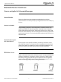


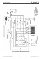


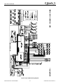
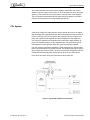
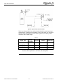
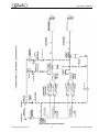

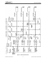
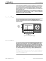

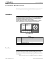
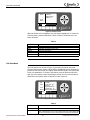
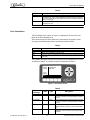
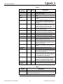
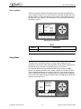
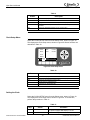
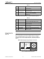
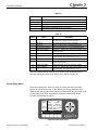
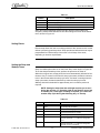
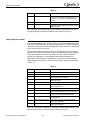
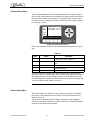


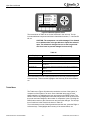
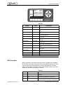

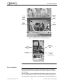

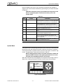
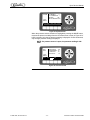


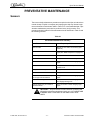

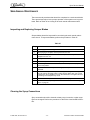
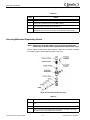

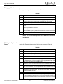

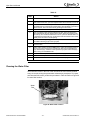

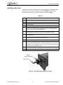
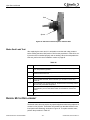
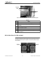
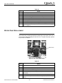
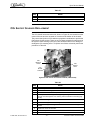
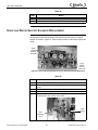
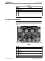
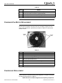
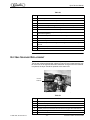
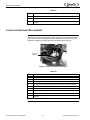

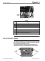
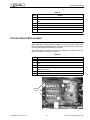
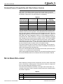

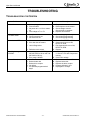


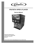
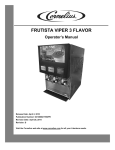

![Service Manual FCB Pinnacle 2 and 4 Flavor [ 005271 ]](http://vs1.manualzilla.com/store/data/006038828_1-2ffb9d6cd82d544c3f733521619945ce-150x150.png)


![Signature Service Manual [ 033869 ]](http://vs1.manualzilla.com/store/data/006016239_1-e43fe3a5f02ed64dc704dbebdd92be62-150x150.png)