1
0311 A OI
GT-2C-L/GT-2C
6(59,&(0$18$/
GT-2H-L/GT-2H
Apartment Intercom System
Master Monitor Station/Sub Master Monitor Station
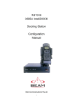
GT-2C-L/GT-2C
Master monitor station
GT-2H-L/GT-2H
Sub master monitor station
OPERATION MANUAL
PRECAUTIONS
General Prohibitions
Prohibition to Dismantle the Unit
Prohibition on Subjecting the Unit to Water
General Precautions
WARNING
(Negligence could result in death or serious injury.)
1. High voltage is present internally. Do not open the case. Electric shock could result.
2. Do not dismantle or alter the unit. Fire or electric shock could result.
3. Do not connect non-specified power sources to the +, - terminals. Also, do not install
two power supplies in parallel to a single input. Fire or damage to the unit could result.
4. Keep the unit away from water or any other liquid. Fire or electric shock could result.
5. Do not put any metal or flammable material into the unit through the openings. Fire or
electric shock could result.
6. Do not use a power supply with a voltage other than the specified. Fire or electric shock
could result.
CAUTION
(Negligence could result in injury to people or damage to
property.)
1. For power supply, use Aiphone power supply model or model specified for use with
system. If non-specified product is used, fire or malfunction could result.
2. Do not install the unit in any of the following locations. Fire, electric shock, or unit
trouble could result.
* Places under direct sunlight or places near heating equipment that varies in temperature.
* Places subject to dust, oil, chemicals, etc.
* Places subject to moisture and humidity extremes, such as bathrooms, cellars, greenhouses, etc.
* Places where the temperature is quite low, such as inside a refrigerated area or in front
of an air conditioner.
* Places subject to steam or smoke (near heating or cooking surfaces).
* Where noise generating devices such as dimmer switches or inverter electrical appliances are close by.
3. Do not put anything on the unit or cover the unit with cloth, etc. Fire or unit trouble
could result.
4. Do not press on the LCD or subject it to high impact. The LCD glass could be punctured and result in an injury.
5. If the LCD is punctured, do not allow skin contact with the liquid crystal inside. Inflammation could result.
* If liquid crystal is ingested, immediately gargle with water and seek medical attention.
* If contact with the eyes or skin occurs, clean with pure water for at least 15 minutes and
seek medical attention.
6. Do not place (install) the unit in locations subject to frequent vibration or impact. Injury or damage could result if the unit falls.
General Precautions
1.
2.
3.
4.
5.
6.
7.
8.
9.
10.
11.
12.
13.
14.
15.
16.
17.
18.
19.
20.
21.
22.
23.
24.
25.
26.
-2-
Keep the unit more than 1 m away from radio or TV set.
This unit is for indoor use only. Do not use outdoors.
In areas where broadcasting station antennas are close by, intercom system may be affected by radio frequency interference.
As to other manufacturer's devices (such as sensor, detectors, door releases) used with this
system, comply with the Specifications and Warranty conditions that the manufacturers or
venders present.
If the unit is down or does not operate properly, unplug the power supply or turn off the
control unit's power switch.
The unit is for wall-mount use only. For desktop applications, use desk stand.
When wall-mounted, the top of the unit may darken. This does not indicate a malfunction.
The unit case may become warm with use, but this is not a unit malfunction.
If a cellular phone is used close by, the unit may malfunction.
The LCD panel is manufactured with very high precision techniques. Please be aware of
this in advance.
Refrain from using this unit in sunlit areas.
At night, due to reduced lighting on the object, the monitor sees more noise and the face
becomes more difficult to see, but this is not malfunction.
Talk within 50 cm (20") or less from the unit. If you stand too far away, it may be difficult
for the other person to hear the communication.
If there are loud noises around the unit (such as music playing or children crying), the
sound may break up and be difficult to hear.
During communication, if you speak before the other person has finished talking, your
voice may not come through clearly. Communication will proceed smoothly if you wait
until the other person has finished before speaking.
At a gate or porch illuminated by a fluorescent lamp, the picture may vary, but this is not a
malfunction.
When outside temperature lowers sharply after rainfall, etc., the inside of the camera may
fog up slightly, causing a blurry picture, but this is not a malfunction. Normal operation
will be restored when moisture evaporates.
Due to the environmental sound around the unit, it may hinder smooth communication, but
this is not a malfunction.
When protection film is affixed to a unit, be sure to remove this before use.
The outline of video images displayed by video door station may differ from that of the
actual person(s) or background, but this is not a malfunction.
If the screen of a video door station freezes during wintertime, the picture may become
difficult to see or the CALL button may not move, but this is not a malfunction.
Aiphone assumes no responsibility for corruption of saved information (such as changes
to or deletion of saved information). Please be aware of this in advance.
The unit turns inoperative during power failure.
When putting a hearing aid into T-mode and approaching the unit, the intercom system
may be affected by radio frequency interference etc., depending on the installation environment.
Be careful about where the unit is used, as use of computers, televisions, or radios near the
unit may affect transmission from the unit or cause unwanted noise.
If very bright light such as direct sunlight hits the camera, white lines may appear on the
screen or the light may create a reflection pattern on the screen. This will make it difficult
to see the caller's face, but this is not a unit malfunction.
Table of Contents
1 NAMES
Master monitor station (GT-2C-L/GT-2C) ....................................................................................................4
Sub master monitor station (GT-2H-L/GT-2H) ..........................................................................................4
2 VIEWING THE SCREEN (MASTER MONITOR STATION) ............................................................................5
3 OPERATING METHOD (MASTER MONITOR STATION)
Turning off the screen display .........................................................................................................................6
Setting the date and time ...................................................................................................................................6
4 RECEIVING CALLS
Answering a call .....................................................................................................................................................7
Door release .............................................................................................................................................................8
Light control ............................................................................................................................................................8
Doctor call (master monitor station) .............................................................................................................8
5 CALLING
Calling security guard stations ........................................................................................................................9
Room-to-room calling...........................................................................................................................................9
6 MONITORING ........................................................................................................................................................10
7 OPERATION DURING COMMUNICATION AND MONITORING
ZOOM/WIDE switching ....................................................................................................................................11
Pan/tilt operation ...............................................................................................................................................11
Individual door zoom picture pre-set (master monitor station) .....................................................11
Night illumination...............................................................................................................................................12
Backlight adjustment and night sensitivity adjustment .....................................................................12
Switching of surveillance camera monitor in common area ............................................................12
8 RECORDING AND PLAYING (MASTER MONITOR STATION)
Automatic recording ..........................................................................................................................................13
Manual recording ...............................................................................................................................................13
Playing recorded pictures ...............................................................................................................................14
Saving recorded pictures .................................................................................................................................15
Erasing recorded pictures ...............................................................................................................................15
9 ALARMS AND RELATED INFO.
OPTION button ....................................................................................................................................................16
Emergency alarm ................................................................................................................................................16
External calls.........................................................................................................................................................17
PRESENCE SECURITY, ABSENCE SECURITY setting (master monitor station) .........................17
Canceling security setting after arrival (master monitor station) ..................................................18
Canceling security alarms (master monitor station)............................................................................18
10 CHANGING SETTINGS (MASTER MONITOR STATION)
Using the MENU ..................................................................................................................................................19
LANGUAGE setting .............................................................................................................................................19
CALL TONE switching .......................................................................................................................................20
Picture memory setting for individual door call....................................................................................20
External call sound time duration setting ................................................................................................21
Individual door call time setting ..................................................................................................................21
Individual door night illumination setting ...............................................................................................22
SECURITY PIN setting .......................................................................................................................................23
DEPARTURE TIMER, ARRIVAL TIMER setting ........................................................................................24
Security alarm sound duration time setting ............................................................................................24
11 TECHNICAL PRECAUTIONS ..............................................................................................................................25
12 SPECIFICATIONS ..................................................................................................................................................25
-3-
1
NAMES
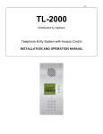
Master monitor station (GT-2C-L/GT-2C)
Color LCD video
monitor
Screen brightness control
(0∼10)
Speaker
Adjust the LCD screen brightness.
Hearing aid T-mode
compatibility symbol*1
(GT-2C-L only)
MENU
CALL
MONITOR
REC/PLAY
button
button
button
button
Receive volume control
(0∼10)
ADJUST button
ZOOM/WIDE
button
Adjust the receive volume during
communication.
At "0", no sound is output.
PAN/TILT button
Indicated with
STWX
button symbols.
STATUS LED (orange) *2
TONE OFF LED (orange) *3
Microphone
*5
Call tone volume
(0∼10)
Adjust the call tone volume.
At "0", no sound is output.
OFF button
DOOR RELEASE button
OPTION button
TALK button
Transmit LED (orange) *4
SECURITY GUARD STATION CALL/LIGHT button
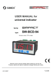
Sub master monitor station (GT-2H-L/GT-2H)
Color LCD video
monitor
Speaker
Screen brightness control
(0∼10)
Adjust the LCD screen brightness.
Hearing aid T-mode
compatibility symbol*1
(GT-2H-L only)
Receive volume control
(0∼10)
CALL button
MONITOR button
ADJUST button
ZOOM/WIDE
button
PAN/TILT button
Indicated with
STWX
button symbols.
OFF button
STATUS LED (orange) *2
TONE OFF LED (orange) *3
Microphone
Adjust the receive volume during
communication.
At "0", no sound is output.
Call tone volume
(0∼10)
Adjust the call tone volume.
At "0", no sound is output.
TALK button
Transmit LED (orange) *4
SECURITY GUARD STATION CALL/LIGHT button
DOOR RELEASE button
OPTION button
*1: This unit emits an electromagnetic field for hearing aids equipped with T-mode to produce clear audio.
*2: The status is indicated by the LED lighting and blinking.
Long-interval blinking:
Blinks every 5.5 seconds
Medium-interval blinking: Blinks every 2.5 seconds
Blinking:
Blinks every 0.5 seconds
*3: When the call tone is set to OFF, this LED will blink with a long interval.
*4: The LED lights up while communicating.
*5: When the handset is connected, the receive volume control cannot be adjusted.
-4-
*5
2
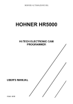
VIEWING THE SCREEN (MASTER MONITOR STATION)
CALLING ENTRANCE1
MAY/26 18:45
Displays during recording or playing
:Recording
:Play
Door release operations are indicated. (This does not exactly
correspond to the door release status of the entrance station.)
The status is displayed.
"CALLING ENTRANCE1": When there is a call from entrance 1
"IN-USE ENTRANCE1": During communication with entrance 1
Displays while screen is being adjusted.
:Backlight adjustment 1, Backlight adjustment 2
:Night adjustment
Displays when absence security or presence security is set.
The current month and date as well as time is displayed.
Symbols are displayed here.
[Screen during calling]
3
OPERATING METHOD (MASTER MONITOR STATION)
To operate this unit, check the symbol and then press the appropriate operation button.
This unit is not operated with touch-panel operation.
Main symbols and function descriptions
Symbol
Do not press on the LCD or subject it to high impact.
The LCD glass could break which could result in an injury.
Operation buttons
Press the button to select the symbol that is
displayed on the screen.
*The operation button name and symbol name
may differ in some cases.
Symbol
The symbols differ according to the screen.
Function description
To manually record
To return to the screen of the previous operation
To display the previous (more recent date/time) picture
To play the recorded pictures
To display the next (older date/time) picture
To save or erase an image
To erase a recorded image
To fast forward the play screen
To pause the play screen
To advance the play screen frame by frame
To reverse the play screen frame by frame
To erase the display
To save recorded pictures
To perform monitoring
To perform room-to-room communication
To perform setting
*Setting can also be done by pressing
[ ZOOM/WIDE] button.
To operate a symbol, press the operation button
that is below the symbol.
Example: To return to the screen of the previous
operation, press the button below [
REC/PLAY].
*In the manual, an explanation is given using the
[
REC/PLAY] button.
-5-
3-1 Turning off the screen display
is displayed on the screen while video images are played. Press
the [
MENU] button to turn off all items displayed on the screen
(date, time, etc.) so that the entire picture is visible.
3-2
1
&$//,1*(175$1&(
Setting the date and time
In the standby mode, press the [
MENU] button.
3
• When the time is set to the initial setting, skip step 2 and go to step 3.
2
0$<
In the "DATE/TIME" screen, press the [S] or [T] button to select the
"Month".
Press the [S] or [T] button to select the "DATE/TIME", and press the
[ MENU] button.
'$7(7,0(
0(18
*8$5'&$//
-$1
6(&85,7<
6(77,1*6
'$7(7,0(
4
Press the [X] button to set the "Month" and the cursor will move to
"Day".
'$7(7,0(
-$1
5
Perform the same steps to set the "Day", "Year", "Hour" and "Minute". After setting the "Minute", press the [ MENU] button to complete the settings.
6
Press the [
OFF] button to return to the standby mode.
1. If there are no operations for approximately 1 minute during the
setup mode, the setting will end automatically. If the settings end
while incomplete, start again from the beginning.
2. A maximum error of ±60 seconds can occur in the displayed time
over a month. Periodically adjusting the time setting is recommended.
3. When power is not supplied to the unit for more than 30 minutes,
the set time will return to its initial setting, "JAN/01/2011 00:00",
and the STATUS LED (orange) will blink with a long interval.
4. If the security sensor is not installed, "SECURITY" will not display.
NOTES: Operations for setting numbers
• [S] button (press once): The date or time increases by one. • [S] button (press and hold for 1 second or more) :
• [T] button (press once): The date or time decreases by one. The date or time increases in succession.
• [W] button (press once) : The cursor moves to the left.
• [T] button (press and hold for 1 second or more) :
• [X] button (press once) : The cursor moves to the right.
The date or time decreases in succession.
•[
MENU] button : The settings are fixed.
-6-
4
RECEIVING CALLS
The unit used in the example pictures is a master monitor station.
4-1
1
2
Answering a call
3
When a call is received from an entrance station, security guard station, or door station, a call tone will sound and the STATUS LED
blinks. If the station has a camera, a picture will be displayed on the
monitor. If the station has a doorbell, a call tone sounds. (Communication is not possible.)
When you are done talking, press the [
OFF] button.
The STATUS LED will go off.
Press the [
TALK] button once, and after the beep, communicate
hands-free. Hands-free communication starts when the STATUS LED
switches from blinking to steadily lit. Transmit LED lights when you
talk, and goes off as you listen to the caller (or hear outside sounds).
NOTES: 1.
2.
• If you press the [
TALK] button for at least one second while talking
hands-free, a beep will be emitted and you can communicate by press-totalk communication.
• In press-to-talk communication, you press the [
TALK] button to talk
and release it to listen.
• Calling turns off after a set amount of time if there is no answer. (Turning off
occurs after 45 seconds for the direct select entrance station.)
• Listening is possible with hearing aids with T-mode. (GT-2C-L/GT-2H-L
only)
• On a sub master monitor station also, the STATUS LED switches from
blinking to steadily lit.
3.
4.
If the call tone volume is turned off, the TONE OFF LED will blink
with a long interval.
When press-to-talk is disabled, press-to-talk communication cannot be used.
During communication, it is not possible to switch back to handsfree communication from press-to-talk communication.
The communication will be ended automatically after approximately 1 minute when hands-free communication is made at the
residential station or after approximately 3 minutes when the handset is used.
The unit emits an electromagnetic field. If a hearing aid with T-mode
is brought too close to the unit, this may cause ear pain. (GT-2C-L/
GT-2H-L only)
Log-data function for missed calls from security guard
station (master monitor station)
When a call from a security guard station is not answered, a call record
picture is recorded (counted as 1 shot). The name of the security guard
station is also displayed.
-$1 *8$5'
0,66('&$//
-7-
4-2
1
Door release
Press the [
tion.
] button while in communication with the entrance sta-
2
Door release is activated at the entrance station.
is displayed
for approx. 5 sec. at the master monitor station. (This does not exactly
correspond to the door release status of the entrance station.)
• If the station has a camera, the door release will also activate during calling.
Depending on the electric door release system that you use, door release may be active only while the door release button is pressed.
4-3
Light control
Turning the entrance light on (when light is installed in common area)
1
2
Press the [ GUARD] button once during entrance station calling,
communication, or monitoring.
The outside light at the entrance will only turn on for the preset duration of time.
This function is not available if a surveillance camera is installed in
the common area.
4-4
Doctor call (master monitor station)
When the specified residence is called using Doctor call (automatic entry), the electric lock is automatically released without a door release operation from the residential station.
1
3
The residential station for which the Doctor call function is set is
called. Press the [
TALK] button as necessary to respond.
In the standby mode, press the [ GUARD] button while pressing the [
TALK] button. Press the button once more to reset the Doctor call function.
• When Doctor call is enabled, the TONE OFF LED blinks with a medium interval.
NOTES: When Doctor call is enabled, the TONE OFF LED function cannot be
used. (It is possible to turn the call tone off.) When calls are transferred to
the security guard station, door release with Doctor call is not possible.
2
This function may not be operated due to the equipment being used.
Press CALL button of the entrance station to unlock a door without a
door release operation from the residential station.
-8-
5
CALLING
The unit used in the example pictures is a master monitor station.
5-1
Calling security guard stations
1
When calling all of the security guard stations, press the [
button while in the standby mode.
1
When calling one of the security guard stations, press the [ MENU]
button, select "GUARD CALL", and press the [ MENU] button.
2
GUARD]
Move the cursor to the security guard station to be called and press the
[ MENU] button. The STATUS LED blinks and calls the indicated
security guard station.
• If there is no answer, a call record will be stored in the security guard station, and notification of the call will be sent to the security guard.
• On a sub master monitor station also, the STATUS LED will blink.
0(18
*8$5'&$//
*8$5'&$//
6(&85,7<
*8$5'
*8$5'
*8$5'
6(77,1*6
*8$5'
'$7(7,0(
NOTES: With a sub master monitor station, all security guard stations will be
called. (Selection is not possible.)
5-2
1
Room-to-room calling
3
When you press the [ CALL] button, you can call all sub master
stations that are connected to the master monitor station.
When you are done talking, press and hold down the [
OFF] button.
The STATUS LED will go off.
• A call will be made to all sub master stations and the STATUS LED will
blink.
• The reply of the other person is not heard.
• On a sub master monitor station also, the STATUS LED will blink.
&$//,1*725220
2
NOTES: 1.
If the other person presses the [
TALK] button, the STATUS LED
lights up and communication between two people is possible.
• Listening is possible with hearing aids with T-mode. (GT-2C-L/GT-2H-L
only)
-9-
2.
Room-to-room communication ends automatically after approximately 10 minutes.
To perform room-to-room communication again, repeat from the
beginning.
If a call is received from the entrance station during room-to-room
communication, the image from the entrance station is displayed at
the master monitor station and sub master monitor station where
communication is taking place. Press the [ OFF] button to end
room-to-room communication, and press the [
TALK] button
to switch to communication with other stations such as entrance
stations.
6
MONITORING
The unit used in the example pictures is a master monitor station.
1
In the standby mode, press the [ MONITOR] button to display the
video image from an individual door station. Audio can heard at the
same time. The STATUS LED will light up.
NOTES: 1.
2.
3.
4.
5.
2
Press the [ MONITOR] button again to display the video image in
order from entrance 1. Audio can heard at the same time.
6.
7.
If there is an operation such as a call, monitoring ends and the call
operation begins.
If the monitor button of a residential station at another residence is
pressed, monitoring of the entrance station switches to the monitor
of the residential station where the monitor button was pressed last.
TALK] button to communicate
During monitoring, press the [
with the individual door station or entrance station being monitored.
With individual door monitoring, monitoring that was initiated first
is prioritized over later attempts at monitoring. (If an attempt is
made to monitor from a sub master station during monitoring from
a master station, an alarm sound will start beeping.)
During monitoring, the display uses a wide picture display. (If the
[
ZOOM/WIDE] button is pressed, the display changes to the
zoom picture.)
When an individual door is being monitored, the illuminator LED
will not light up at night until the TALK button is pressed.
Monitoring will automatically end after 30 seconds.
1. It will take a moment after pressing the MONITOR button for the
picture to display, so please wait for the monitor picture to display
before performing the next button operation.
2. This function may not be usable depending on the equipment being
used.
• Listening is possible with hearing aids with T-mode. (GT-2C-L/GT-2H-L only)
- 10 -
7
OPERATION DURING COMMUNICATION AND MONITORING
The unit used in the example pictures is a master monitor station.
7-1
1
ZOOM/WIDE switching
Press the [
ZOOM/WIDE] button when a picture is displayed.
• Switching between zoom ⇔ wide occurs each time the button is pressed.
[Wide picture]
NOTES: 1.
2.
[Zoom picture]
When the caller is not shown in the center of the picture, the zoom
picture can be moved up, down, left, and right. (Refer to section 7-2.)
For an individual door, when the display changes from the wide picture to the zoom picture, the zoom picture starts at the preset (section
7-3) position.
The wide picture may be distorted in comparison with the zoom picture
due to the characteristics of the camera, but this is not a malfunction.
7-2
1
Pan/tilt operation
When a zoom picture is displayed, press the [S], [T], [W], or [X]
button.
•
•
•
•
•
[S]: Up
[T]: Down
[W]: Left
[X]: Right
Moving diagonally is also possible.
1. The image range of the zoom picture and wide picture differs. The
edges of the wide picture do not display with the zoom picture.
2. At night, due to reduced lighting on subjects, subjects may become
blurry and difficult to see if the zoom picture is moved up, down,
left, or right. (The same thing occurs with moving subjects.)
7-3
Individual door zoom picture pre-set (master monitor station)
The picture can be set to display using a set zoom picture position for
when a call is received from an individual door.
2
• When switching from the wide picture to the zoom picture, the zoom picture
displays starting from the pre-set position.
1
When an individual door zoom picture is displayed, press the [S],
[T], [W], or [X] button. (Ex. Pressing the [S] button moves the picture up.)
• While viewing the picture, set the desired picture position.
NOTES: 1.
2.
3.
To change the zoom picture position that has been set, perform the
zoom picture settings again. The previous settings will be overwritten.
The zoom picture position set with the master monitor station will
also be displayed at the sub master monitor station. * Pre-sets cannot
be set from a sub master monitor station.
The picture will display according to the individual door call record
setting.
- 11 -
Press the [
ZOOM/WIDE] button (for at least 2 seconds).
• A beep will sound and the position setting will be completed.
7-4
Night illumination
At night, the illuminator LED lights up during an entrance station or individual door station call. Also, the LED can be made to light up during
monitoring of a individual door station.
When a call is made from an entrance station or individual door
station
Lighting up the illuminator LED when monitoring an individual door
station
1
1
If the call button of the entrance station or individual door station is
pressed, the illuminator LED will light up.
When the [
TALK] button is pressed during monitoring, communication starts and the illuminator LED will light up.
1. Be aware that inside sound can be heard at the entrance.
2. For entrance stations, the LED lights up when monitoring starts.
the illuminator
LED will light up.
2
2
When communication ends, the illuminator LED will go out.
When communication ends, the illuminator LED will go out.
NOTES: 1.
2.
7-5
Distinguishing between day and night is automatically done by the
entrance station or individual door station.
Operation will vary depending on the entrance station setting and
individual door night illumination setting.
Backlight adjustment and night sensitivity adjustment
Day
When a unit is installed at an entrance or individual door where backlighting makes viewing difficult, adjustment for easier viewing is performed.
Night
At night or when the area around the entrance or an individual door is
dark, adjustment for easier viewing is performed.
1
When the picture is difficult to see, press the [
ADJUST] button
to switch between the three modes "Backlight adjustment 1", "Backlight adjustment 2" and "No adjustment".
1
2
For an individual door, press the [
ADJUST] button for at least 2
seconds to make a beep sound and to set the mode being displayed
(master monitor station only).
NOTES: 1.
2.
7-6
When the picture is difficult to see, press the [
ADJUST] button
to switch between "Night adjustment" and "No adjustment".
NOTES: 1.
2.
is displayed during "Backlight adjustment 1" and "Backlight
adjustment 2".
When display is performed again, entrance stations will display
using the default setting while individual door stations will display
using the mode that was last set.
3.
4.
is displayed during night adjustment.
When display is performed again, both the entrance and individual
door stations will display without any previously set adjustment
being applied.
Distinguishing between day and night is automatically done by the
entrance station or individual door station.
Pressing the [
ADJUST] button at night makes the caller's
face easier to see, but moving subjects may be more difficult to see.
Switching of surveillance camera monitor in common area
When a surveillance camera is mounted in the common area
Press the [ GUARD] button during calling from the entrance station,
communication with the entrance, or entrance monitoring to switch to the
will display.
surveillance camera video image.
Press the button again to return to the entrance station video image.
During switching between the entrance camera and surveillance camera in common area, the image on the monitor may become momentarily distorted, but this is not a malfunction.
- 12 -
8
RECORDING AND PLAYING (MASTER MONITOR STATION)
8-1
Automatic recording
If call is received from an entrance station or individual door station, resymbol blinks on
cording starts automatically. During recording, the
the screen.
Zoom pictures (from 1st shot to 6th shot)
1st shot
2nd shot
• Recording starts approximately 2 seconds after the CALL button of an entrance
station or individual door station is pressed. A maximum length of approximately 6 seconds (6 shots) can be recorded, with 1 image and 1 shot for each second.
• In the initial settings, pictures are automatically recorded. All six pictures are
zoom pictures at a pre-set position.
• A maximum of 40 pictures can be recorded (combined total of automatic recording and manual recording pictures). When 40 pictures are exceeded, new pictures overwrite old pictures starting from the oldest recorded date. (Up to 10
protected picture cannot be overwritten.)
• Automatic recording will also start if a call is made from an entrance station or
individual door station that is being monitored.
• When a call from the security guard station is not answered, 1 shot is recorded in
the call record.
• If an operation with high priority is performed during recording, recording stops
and operation is performed according to the order of priority.
NOTES: 1.
2.
3.
8-2
1
6th shot
1. During installation, if a zoom ⇔ wide range is set in the entrance
station call picture settings, the number of recorded pictures may
not switch between 3 zoom pictures ⇔ 3 wide pictures.
2. If switching of the surveillance camera in common area is performed during recording, a distorted picture may be recorded, but
this is not a malfunction.
The automatic recording function cannot be cancelled.
Pictures recorded at individual door stations are recorded using the
method that has been set (section 10-4). Picture recording at entrance stations is set in advance. However, if switching between
zoom and wide is performed during automatic recording, the displayed picture will be recorded.
The picture during monitoring is not automatically recorded. If you
wish to record this picture, press the [
REC/PLAY] button.
Manual recording
Display the video image of the location to be recorded with an operation such as a [ MONITOR] button operation.
NOTES: 1.
2.
Manual recording is not possible during automatic recording (for
approximately 7 seconds after receiving a call from an entrance
station or individual door station).
After the end of automatic recording (approximately 7 seconds after receiving a call from an entrance station or door station), recording of another image in addition to the automatically recorded
image can be performed.
2
Press the [
REC/PLAY] button. The
screen and recording starts.
symbol flashes on the
• A maximum length of approximately 6 seconds (6 shots) can be recorded, with
1 image and 1 shot for each second.
• A maximum of 40 pictures can be recorded (combined total of automatic recording and manual recording pictures). When 40 pictures are exceeded, new pictures overwrite old pictures starting from the oldest recorded date. (Up to 10
protected shots cannot be overwritten.)
• If an operation with high priority is performed during recording, recording stops
and operation is performed according to the order of priority.
If switching of the surveillance camera in common area is performed
during recording, a distorted picture may be recorded, but this is not a
malfunction.
- 13 -
8-3
Playing recorded pictures
If there are automatically recorded pictures, such as those taken while you
were out, the STATUS LED blinks with a long interval during standby
mode.
1
Press the [
REC/PLAY] button in the standby mode to display the
picture with the most recent date and time.
•
displays on the screen when there are no recorded pictures.
The status is displayed.
Sequence number of image currently being displayed/total recorded images
Displays on unplayed images
Displays when image is saved
JA N/01/2011 18:45
07/16
The recorded pictures are displayed in order based on the date set
during recording.
[Play-waiting screen]
07/16
2
JA N/01/2011 18:45
Time and date of
recording
Press the [
REC/PLAY] button on the play-waiting screen. The
recorded image is played. When the play of one image ends, the next
image is displayed.
[During play]
Lit up
07/16
JAN/01/2011 18:45
[Next picture]
06/16
* In addition, the operations shown below are also possible in the play-waiting
screen.
• [ MONITOR] button:
To display the next (more recent date/time) picture.
When the button is pressed for 1 second or more, the first picture of the set
will display and then the other pictures can be checked in succession in the
direction of the newer dates and times by keeping the button pressed.
(If the [
MONITOR] button is pressed while the picture with the most
recent date and time is displayed, the picture with the oldest date and time
will display.)
• [ CALL] button:
To display the previous (older date/time) picture.
When the button is pressed for 1 second or more, the first picture of the set
will display and then the other pictures can be checked in succession in the
direction of the older dates and times by keeping the button pressed.
•[
MENU] button:
To save or erase an image. (Refer to sections 8-4 and 8-5.)
JAN/01/2011 17:45
3
When advancing the play screen frame-by-frame, press the [
REC/PLAY] button during playback to pause. The play advances
frame-by-frame each time the [ CALL] button is pressed.
4
Press the [
OFF] to end playback.
* The operations shown below are possible during play.
•[
REC/PLAY] button:
To pause play.
• [ MONITOR] button:
To display the next (older date/time) picture.
• [ CALL] button:
To display the picture with the next oldest date after fast forward playing.
•[
MENU] button:
The symbols on the screen can be turned on and off.
* In addition, the operations shown below are also possible during pause.
•[
REC/PLAY] button:
To return to the play screen.
• [ MONITOR] button:
The play is reversed frame by frame each time the button is pressed. When
the frames of one image end, the unit returns to the play-waiting screen.
• [ CALL] button:
The play advances frame by frame each time the button is pressed.
•[
MENU] button:
The picture with the next oldest date displays on the play-waiting screen.
NOTES: 1.
2.
- 14 -
If there are no operations for at least approximately 1 minute, it
will end automatically.
If a call is received during play, the call tone sounds and play is
forcibly ended.
8-4
Saving recorded pictures
10 images can be saved from the recorded images (maximum of 40 images).
Saved pictures are not overwritten.
1
2
Press the [
MONITOR] button.
07/16
JA N/01/2011 18:45
Display the picture that you want to save in the play-waiting screen.
(Refer to section 8-3.)
Press the [
MENU] button to display the save/erase selection screen.
07/16
JA N/01/2011 18:45
3
is displayed when saving is performed. If the picture has already
been saved, the save is canceled.
Each time the [
MONITOR] button is pressed, the operation
switches between save and cancel.
NOTES: 1.
2.
"CANNOT BE SAVED. MAX 10 IMAGES" is displayed if the number of possible saves is exceeded. Cancel unnecessary saved image.
Images that have had the save canceled are not erased, but they are
overwritten if the number of recorded images is exceeded.
07/16
MAY/26/2011
18:45
JA
IMAGE SAVED
8-5
SAVE CANCELLED
Erasing recorded pictures
3
It is also possible to erase saved recorded pictures.
The erasure of recorded pictures is performed for each picture in turn.
1
MAY/26/2011
18:45
JA
07/16
Press the [
Press the [
MENU] button to erase the picture.
REC/PLAY] button to stop erasing.
Display the picture that you want to erase in the play-waiting screen.
(Refer to section 8-3.)
Press the [
07/16
0$<
JA N/01/2008 18:45
MENU] button to display the save/erase selection screen.
07/16
JA N/01/2011 18:45
(5$6(,0$*("
12
<(6
Once a picture is erased, it cannot be restored
NOTES: When there are multiple recorded pictures, the next (older date) picture
displays when erasing is completed.
2
Press the [
MENU] button.
07/16
JAN/01/2011 18:45
- 15 -
9
ALARMS AND RELATED INFO.
The unit used in the example pictures is a master monitor station.
9-1
OPTION button
Pressing the [
OPTION] button allows for operation of connected units
to be performed such as turning lights on and off.
9-2
Emergency alarm
1
Press and lock the emergency alarm switch (or when there is a line off trouble).
2
An alarm will sound from the residential station, and a warning signal
will be sent to the security guard station. An emergency screen is displayed on the monitor.
4
Press the [
TALK] button to communicate with the security guard
station. The STATUS LED will light up. After communication, the
emergency alarm will begin to sound again.
5
Release the lock position of the emergency alarm switch to return to
the standby position (restore the system to normal status).
• Only the alarm sounds at sub master monitor stations.
$/$50$&7,9$7('
3
%HHS
%HHS
%HHS
When there is a call from the security guard station, the warning
sound will change to a call tone that will sound for the set amount of
time. The STATUS LED blinks.
NOTES: 1.
2.
3.
4.
5.
- 16 -
On the residential station, the emergency alarm and call tone will
be emitted at level 10 (HIGH) volume, regardless of the volume
setting.
The emergency alarm function can be activated even while the system is in use.
Residential stations within the same residence will be unable to
receive normal calls or doorbell calls while the emergency alarm is
sounding. It is only possible to respond to calls from the security
guard station.
During the emergency alarm, the entrance station cannot make
calls to the residential station or to the security guard station that
are producing emergency alarms.
Emergency alarms will also sound at individual door stations, and
the illuminator LED will blink.
9-3
1
External calls
When a separately-installed sensor is activated or the CALL button is
pressed, the alarm sounds, and the warning screen displays on the
monitor and blinks.
2
Press the [ OFF] button or [
REC/PLAY] button ([
ton for GT-2H-L/GT-2H) to stop the alarm sound.
OFF] but-
• Only the alarm sounds at sub master monitor stations.
3UUUUUU
6(1625$&7,9$7('
5(6(7
NOTES: 1.
2.
3.
9-4
PRESENCE SECURITY, ABSENCE SECURITY setting (master monitor station)
Set the security settings for individual doors and windows. By security
settings, intrusions at individual doors or windows will be detected and a
security alarm will sound.
4
• PRESENCE SECURITY
Security setting for when resident is at home sleeping that is applied immediately after setting.
• ABSENCE SECURITY
Security setting for when resident is away that is applied after the delay time
(section 10-9) elapses after setting.
1
2
3
The alarm sound time is set in the external settings. (Refer to section 10-5.)
The initial setting is 10 minute.
When the alarm sound time is set for 1 hour or for the alarm to
sound continuously, the monitor warning screen will go out after
approximately 10 minutes.
Even if the call tone volume is set to 0 (OFF), it will sound at a
level equivalent to 10 (HIGH).
In the standby mode, press the [
In the "SECURITY" screen, confirm the locations that are on alert
among sensors 1 through 3 (only sensors for which security settings
have been performed will display). To change settings, move the cursor to the location to be changed and press the [ MENU] button.
• Locations will display according to the locations selected when settings
were performed last.
SECURITY
MENU] button.
Select "SECURITY" in the "MENU" screen, and press the [
MENU] button.
SENSOR1
[ ENEBLE ]
SENSOR2
[ ENABLE ]
SENSOR3
[ DISABLE ]
SELECT SENSOR TO BE ON ALART.
Select "PRESENCE SECURITY" or "ABSENCE SECURITY" in the
"SECURITY" screen, and press the [ MENU] button.
(Ex.: Selection of "PRESENCE SECURITY")
SECURITY
5
Select "ENABLE" or "DISABLE" in the "SECURITY" screen for
each sensor, and press the [ MENU] button.
6
Press the [
REC/PLAY] button to return to the step 3 screen, move
the cursor with "PRESENCE SECURITY" or "ABSENCE SECURITY" and press the [ CALL] button.
7
PRESENCE SECURITY is set. For "ABSENCE SECURITY", "ABSENCE SECURITY" is set after the set time elapses.
PRESENCE SECURITY
ABSENCE SECURITY
[ S1
:ON
S2
S3
]
:ALARM ACTIVATED
START
• The STATUS LED blinks with a medium interval.
• If there are no operations for approximately 1 minute, the screen display
will end.
• If selected locations are open, they will display in red and "CHECK STATUS SENSOR" will display on the screen.
• To cancel settings, press the [
MENU] button (cancel) at the step 3
screen.
- 17 -
9-5
1
Canceling security setting after arrival (master monitor station)
When the ABSENCE SECURITY setting in 9-4 is set, if an individual door is opened, a screen will display and the alarm will sound.
3
Restoration occurs when the security PIN is correct.
• If the security PIN is not correct, "WRONG SECURITY PIN." will display.
• There is no limit to the number of times the PIN can be entered, but if a correct security PIN is not entered within the set delay time (10-9 DEPARTURE TIMER, ARRIVAL TIMER setting), a security alarm sounds.
• At this time, operation other than an emergency alarm cannot be performed.
Ex.: When a call is made from the entrance station, communication will not
start. (The master monitor station is in occupied mode.)
• Even if the call tone volume is set to 0 (OFF), it will sound at a level equivalent to 10 (HIGH).
3LSLSL
6(1625$&7,9$7('
5(6(7
2
Press the [
REC/PLAY] to display the security PIN input screen.
Input the security PIN by pressing the [S], [T], [W], and [X] buttons.
• When a security PIN is not used, press the [
store.
REC/PLAY] button to re-
(17(56(&85,7<3,1
&/($5
9-6
1
Canceling security alarms (master monitor station)
When the PRESENCE SECURITY setting in 9-4 is set, if an individual door is opened, the security screen will display and the alarm
will sound.
When ABSENCE SECURITY is set, the security screen will display
and the alarm will sound after the DEPARTURE TIMER or ARRIVAL TIMER has elapsed.
3
Press the [
REC/PLAY] to display the security PIN input screen.
Input the security PIN by pressing the [S], [T], [W], and [X] buttons.
• When a security PIN is not used, press the [
store.
• Alarms will also sound at individual door stations, and the illuminator LED
will blink.
• Even if the call tone volume is set to 0 (OFF), it will sound at a level equivalent to 10 (HIGH).
REC/PLAY] button to re-
(17(56(&85,7<3,1
&/($5
Prrrrrr
SENSOR1 ACTIVATED.
4
STOP
Restoration occurs when the security PIN is correct.
• If the security PIN is not correct, "WRONG SECURITY PIN." will display.
• Depending on the settings at installation, an alarm may be output to a security guard station.
2
Press the [
REC/PLAY] button or the [
OFF] button.
• The alarm sound will stop.
- 18 -
10
CHANGING SETTINGS (MASTER MONITOR STATION)
The screen may vary depending on the equipment being used.
10-1 Using the MENU
1
2
In the standby mode, press the [
3
MENU] button.
Press the [S] or [T] button to select "SETTINGS", and press the
[ MENU] button.
Press the [S], [T], [W], and [X] buttons in the "SETTINGS" screen
to select the item to be confirmed, and press the [ MENU] button.
6(77,1*6
&$//721(
/$1*8$*(
*8$5'&$//
3,&785(0(025<
'225
6(&85,7<
87,/,7<
6(&85,7<
0(18
6(77,1*6
'$7(7,0(
4
To finish changing settings, press the [ OFF] button to return to the
standby mode. In other cases, set by pressing the [ MENU] button.
Press the [
REC/PLAY] button to cancel the settings and return to
the previous screen.
2
Select the desired language in the "LANGUAGE" screen.
10-2 LANGUAGE setting
The initial language setting is "ENGLISH".
1
After performing steps 1 and 2 in section 10-1, select "LANGUAGE"
in the "SETTINGS" screen and press the [ MENU] button.
- 19 -
Press the [
MENU] button to complete the settings.
/$1*8$*(
10-3 CALL TONE switching
Separate sounds can be selected for entrance stations, individual door stations, and security guard stations from 5 sound types.
1
After performing steps 1 and 2 in section 10-1, select "CALL TONE"
in the "SETTINGS" screen and press the [ MENU] button.
2
Select one from "ENTRANCE/DOOR/GUARD" in the "CALL
TONE" screen, and press the [ MENU] button.
CALL TONE
ENTRANCE
[
1
]
DOOR
[
2
]
GUARD
[
3
]
3
In the separate "CALL TONE" screens for "ENTRANCE/DOOR/
GUARD", select the desired call tones. The selected call tone sounds,
MENU] button to
enabling you to check the sound. Press the [
complete the settings.
• The sub master monitor station call tone will also change.
(175$1&(&$//721(
Initial settings
ENTRANCE :♪ 1
DOOR
:♪ 2
GUARD
:♪ 3
10-4 Picture memory setting for individual door call
For automatic recording at an individual door, select the recording method
for recording pictures (up to 6 for each image) from the following four
types. In the initial settings, all six pictures are zoom pictures at a pre-set
position.
1
After performing steps 1 and 2 in section 10-1, select "PICTURE
MEMORY" in the "SETTINGS" screen and press the [
MENU]
button.
2
Select the picture recording method in the "PICTURE MEMORY"
screen.
Pictures are automatically recorded. All six
pictures are zoom pictures at a pre-set position.
PICTURE MEMORY (DOOR)
x6
Press the [
Pictures are automatically recorded. All
six pictures are wide pictures.
MENU] button to complete the settings.
3,&785(0(025<'225
x6
x3+
x3
x3+
x3
[
Pictures are automatically recorded. First three
pictures are zoom pictures at a pre-set position,
and the next three pictures are wide pictures.
Pictures are automatically recorded. First three
pictures are wide pictures, and the next three
pictures are zoom pictures at a pre-set position.
NOTES: The set picture recording method does not apply to pictures displayed
during a call from the entrance station.
- 20 -
[
[
[
[
[
10-5 External call sound time duration setting
Select the external call sound time duration. The initial setting is "10
MIN.".
1
2
3
After performing steps 1 and 2 in section 10-1, select "UTILITY" in
the "SETTINGS" screen and press the [ MENU] button.
Select the sound time in the "UTILITY-CALL TIMER" screen. Press
the [ MENU] button to complete the settings.
UTILITY-CALL TIMER
Select "ALARM TIMER" in the "UTILITY" screen, and press the
[ MENU] button.
10SEC.
1HOUR
1MIN.
CONT.
"CONT." = Continuous
10MIN.
87,/,7<
$/$507,0(5
10-6 Individual door call time setting
3
Select the individual door call time. The initial setting is "45 SEC.".
1
2
After performing steps 1 and 2 in section 10-1, select "DOOR" in the
"SETTINGS" screen and press the [ MENU] button.
Select "CALL DURATION" in the "DOOR" screen, and press the
[ MENU] button.
Select the call time in the "CALL DURATION" screen.
[ MENU] button to complete the settings.
&$//'85$7,21
6(&
6(&
6(&
6(&
6(&
'225
&$//'85$7,21
>6(&@
1,*+7,//80,1$7,21>(1$%/(@
- 21 -
Press the
10-7 Individual door night illumination setting
Select whether the door station illuminator LED is enabled or disabled.
The initial setting is "ENABLE".
1
2
3
After performing steps 1 and 2 in section 10-1, select "DOOR" in the
"SETTINGS" screen and press the [ MENU] button.
Select "NIGHT ILLUMINATION" in the "DOOR" screen, and press
the [ MENU] button.
'225
&$//'85$7,21
>6(&@
1,*+7,//80,1$7,21>(1$%/(@
- 22 -
Select "ENABLE" or "DISABLE" in the "NIGHT ILLUMINATION"
screen. Press the [ MENU] button to complete the settings.
1,*+7,//80,1$7,21
(1$%/(
',6$%/(
10-8 SECURITY PIN setting
The security PIN to be used can be set when performing PRESENCE
SECURITY and ABSENCE SECURITY setting.
The initial setting is "DISABLE", when "ENABLE" is selected, the initial
setting for the security PIN is [S], [X], [T], and [W].
1
After performing steps 1 and 2 in section 10-1, select "SECURITY" in
the "SETTINGS" screen and press the [ MENU] button.
2
Select "SECURITY PIN" in the "SECURITY" screen, and press the
[ MENU] button.
5
After "CHANGE SECURITY PIN?" displays in the "SECURITY
PIN" screen, press the [ MENU] button.
6(&85,7<3,1
&+$1*(6(&85,7<3,1"
12
<(6
SECURITY
SECURITY PIN
ABSENCE SECURITY
6
ALARM TIMER
After "ENTER SECURITY PIN." is displayed, enter the security PIN
with the [S], [T], [W], and [X] buttons.
• To re-enter the security PIN from the start, press the [
ton.
REC/PLAY] but-
6(&85,7<3,1
3
Select "RESET SETTING" on the "SECURITY PIN" screen and select whether a security PIN is used in the restoration method.
"ENABLE" = Used
"DISABLE" = Not used
4
(17(56(&85,7<3,1
&/($5
When "ENABLE" is selected, select "PIN SETTING" in the "SECURITY PIN" screen, and press the [ MENU] button.
6(&85,7<3,1
3,16(77,1*
7
5(6(76(77,1*
When settings for the 4 items are input, "CHANGE SETTING?" is
displayed. Press the [ MENU] button to complete the settings.
6(&85,7<3,1
&+$1*(6(77,1*"
12
- 23 -
<(6
10-9 DEPARTURE TIMER, ARRIVAL TIMER setting
With ABSENCE SECURITY, the delay time from when an action causing
a warning response is detected to when a warning is actually sent can be
set. The initial setting is "60 SEC.".
DEPARTURE TIMER = Time from when ABSENCE SECURITY is set
to when user leaves
ARRIVAL TIMER = Time from when user arrives to when ABSENCE
SECURITY is canceled
1
After performing steps 1 and 2 in section 10-1, select "SECURITY"
in the "SETTINGS" screen and press the [ MENU] button.
2
Select "ABSENCE SECURITY" in the "SECURITY" screen, and
press the [ MENU] button.
3
Select "DEPARTURE TIMER" or "ARRIVAL TIMER" in the "ABSENCE SECURITY" screen, and press the [ MENU] button.
(Ex.: Selection of "DEPARTURE TIMER")
ABSENCE SECURITY
DEPARTURE TIMER
ARRIVAL TIMER
SECURITY
SECURITY PIN
4
ABSENCE SECURITY
ALARM TIMER
Select the delay time in the "DEPARTURE TIMER SETTING"
screen, and press the [
MENU] button. Repeat the same operation
for the "ARRIVAL TIMER" screen.
DEPARTURE TIMER SETTING
0SEC.
120SEC.
30SEC.
300SEC.
60SEC.
600SEC.
TIME DURATION FOR THE ALARM SET
1. Setting the "DEPARTURE TIMER" to "0 SEC." will make a security alarm sound immediately when a door or window is opened
when ABSENCE SECURITY is set.
2. Setting the "ARRIVAL TIMER" to "0 SEC." will make a security
alarm sound immediately when a door or window is opened after
arrival.
10-10 Security alarm sound duration time setting
Select the security alarm sound time duration. The initial setting is "10
MIN.".
1
2
3
After performing steps 1 and 2 in section 10-1, select "SECURITY" in
the "SETTINGS" screen and press the [ MENU] button.
Select "ALARM TIMER" in the "SECURITY" screen, and press the
[ MENU] button.
SECURITY
SECURITY PIN
ABSENCE SECURITY
ALARM TIMER
- 24 -
Select the sound time in the "SECURITY ALARM TIMER" screen.
Press the [ MENU] button to complete the settings.
SECURITY ALARM TIMER
10SEC.
1HOUR
1MIN.
CONT.
10MIN.
"CONT." = Continuous
11
TECHNICAL PRECAUTIONS
• Operating temperature: 0°C to +40°C (+32°F to +104°F)
• The video image may distort when the door release is activated. But this
is not a unit malfunction.
• If a zoom/wide or pan/tilt operation is performed during communication with the entrance station, noise will be produced at the entrance
station, but this is not a malfunction.
• Cleaning: Clean the units with a soft cloth dampened with a neutral
household cleanser. Do not use any abrasive cleaner or cloth.
12
SPECIFICATIONS
• Power supply:
• Current consumption:
• Communication:
• Video monitor:
• Dimensions:
• Weight:
• If there is a system malfunction, unplug the power supply and contact a
qualified technician for service.
DC 24 V (from power supply)
GT-2C-L: (MAX) Approx. 390mA
GT-2H-L: (MAX) Approx. 240mA
GT-2C: (MAX) Approx. 260mA
GT-2H: (MAX) Approx. 110mA
Hands-free communication/
Press-to-talk communication
3-1/2" TFT color LCD
140 (H) × 190 (W) × 30 (D) (mm)
5-1/2 (H) × 7-1/2 (W) × 1-1/4 (D) (inches)
GT-2C-L: Approx. 520 g (1.15 lbs.)
GT-2C: Approx. 470 g (1.04 lbs.)
GT-2H-L: Approx. 480 g (1.06 lbs.)
GT-2H: Approx. 440 g (0.97 lbs.)
- 25 -
Aiphone warrants that its products have no material or workmanship defects under normal use conditions for two years after delivery to the end user. Aiphone will perform repair or replacement
free of charge if the product is defective and the warranty applies to the defect. Aiphone reserves unto itself the sole right to make the final decision whether there is a defect in materials and/or
workmanship and whether or not the product is under warranty. This warranty shall not apply to any Aiphone product which has been subject to misuse, neglect, accident, or to use in violation of
instructions furnished, nor extended to units which have been repaired or altered outside of the factory. This warranty does not cover batteries or damage caused by batteries used in connection
with the unit. Any repairs must be made at the shop or place designated in writing by Aiphone. Aiphone will not be responsible for any costs incurred during on-site service calls. Aiphone will not
provide compensation for any loss or damage incurred by the breakdown or malfunction of its products during use, or for any consequent inconvenience or losses that may result.
indicates applicability to the EU.
This equipment has been tested and found to comply with the limits for a Class B digital device, pursuant to Part 15 of the FCC Rules. These limits are designed to provide
reasonable protection against harmful interference in a residential installation. This equipment generates, uses, and can radiate radio frequency energy, and if not installed and used
in accordance with the instructions, may cause harmful interference to radio communications. However, there is no guarantee that interference will not occur in a particular
installation. If this equipment does cause harmful interference to radio or television reception, which can be determined by turning the equipment off and on, the user is encouraged
to try to correct the interference by one or more of the following measures: • Reorient or relocate the receiving antenna • Connect the equipment into an outlet on a circuit different
from that to which the receiver is connected. Increase the separation between the equipment and receiver. • Consult the dealer or an experienced radio/TV technician for help.
http://www.aiphone.net/
AIPHONE CO., LTD., NAGOYA, JAPAN
AIPHONE CORPORATION, BELLEVUE, WA, USA
AIPHONE S.A.S., LISSES-EVRY, FRANCE
- 26 -