1
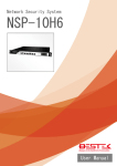
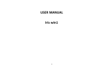
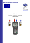
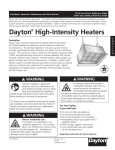
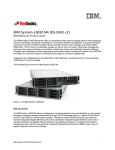
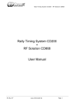
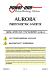
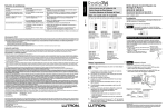
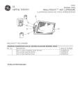
TouchTunes Music Corporation
Maestro Parts and Service Manual
First Edition (October 2005)
900164-001 Rev 00
TouchTunes and the TouchTunes logo are trademarks of TouchTunes Music Corporation.
Bose and Accoustimass are registered trademarks of Bose Corporation.
All other brand and product names are trademarks or registered trademarks of their respective corporations.
The mention of any product does not constitute an endorsement by TouchTunes Music Corporation.
This manual, as well as the software and hardware described in it, are furnished under a lease agreement and may only be
copied or used within accordance with the terms of such lease agreement. The content of this manual is furnished for
informational use only, is subject to change without notice, and should not be construed as a commitment by TouchTunes
Music Corporation. TouchTunes Music Corporation assumes no responsibility or liability for any errors or inaccuracies that
may appear in this document.
Except as permitted by such lease agreement, no part of this publication may be reproduced, stored in any retrieval
system, or transmitted, in any form or by any means, electronic, mechanical, recording, or otherwise, without prior written
consent of TouchTunes Music Corporation.
Changes are periodically made to the information herein; these changes will be incorporated into new editions of this
publication. TouchTunes may make improvements and/or changes in the products and/or software programs described in
this publication at any time.
If you have comments on this manual or the products it describes, address them to:
TouchTunes Music Corporation
Attention: Publications
1110 Lake Cook Road, Suite 100
Buffalo Grove, IL 60089
Telephone: 1-888-338-JUKE
Support hotline: 1-888-711-JUKE
Fax: (847) 419-3304
TouchTunes may use or distribute whatever information you supply in any way it believes appropriate without incurring any
obligations to you.
Copyright © 2005 TouchTunes Music Corporation. All rights reserved, including those to reproduce this publication or parts
thereof in any form without permission in writing from TouchTunes Music Corporation.
:
Contents
Chapter 1
Parts List . . . . . . . . . . . . . . . . . . . . . . . . . . . . .3
Chapter 2
Servicing the Maestro SBC . . . . . . . . . . . . . .11
Overview ...................................................................11
Parts list ....................................................................11
Removing and opening the SBC...............................12
ISA/PCI card .............................................................12
Removal . . . . . . . . . . . . . . . . . . . . . . . . . . . . . . . . . . . .12
Installation. . . . . . . . . . . . . . . . . . . . . . . . . . . . . . . . . . .12
CPU and fan..............................................................13
Removal . . . . . . . . . . . . . . . . . . . . . . . . . . . . . . . . . . . .13
Installation. . . . . . . . . . . . . . . . . . . . . . . . . . . . . . . . . . .13
Lithium clock battery .................................................13
Removal . . . . . . . . . . . . . . . . . . . . . . . . . . . . . . . . . . . .13
Installation. . . . . . . . . . . . . . . . . . . . . . . . . . . . . . . . . . .13
RAM card ..................................................................14
Removal . . . . . . . . . . . . . . . . . . . . . . . . . . . . . . . . . . . .14
Installation. . . . . . . . . . . . . . . . . . . . . . . . . . . . . . . . . . .14
Hard drive..................................................................14
Removal . . . . . . . . . . . . . . . . . . . . . . . . . . . . . . . . . . . .14
Installation. . . . . . . . . . . . . . . . . . . . . . . . . . . . . . . . . . .14
Riser/sound card .......................................................15
Removal . . . . . . . . . . . . . . . . . . . . . . . . . . . . . . . . . . . .15
Installation. . . . . . . . . . . . . . . . . . . . . . . . . . . . . . . . . . .15
Power supply.............................................................16
Removal . . . . . . . . . . . . . . . . . . . . . . . . . . . . . . . . . . . .16
Installation. . . . . . . . . . . . . . . . . . . . . . . . . . . . . . . . . . .16
1
:
2
Chapter 1: Parts List
Chapter 1
Parts List
Notes
1.
Unless otherwise specified, all screws
are Item 25, 8-32 X 0.250 HEX.
2.
See page 6 for details.
3.
Gasket not shown.
4.
Cable-tie and harness not shown.
Chapter 1: Parts List
Notes
4
1.
Unless otherwise Specified, all screws
are item 25, 8-32 X 0.250 HEX.
2.
Install Item 57 with included hardware.
3.
nsert filter item 33, (not shown).
4.
Cable-tie and harness not shown.
Chapter 1: Parts List
5
Chapter 1: Parts List
Notes
6
1.
Unless ttherwise specified, all screws are
item 25, 8-32 X 0.250 HEX.
2.
Insert item 53 Split Ring (not shown).
3.
Applied Meastro Label item 32 (not shown).
4.
Cable-tie and harness not shown.
Chapter 1: Parts List
Item
TouchTunes
Part #
Part #
Rev.
Description
Qty
1
400062-001
267521-111
0
HOUSING,CONSOLE,FRONT,SILVER
1
2
400072-001
267522-111
0
HOUSING,CONSOLE,REAR,CASTING
1
3
400101-001
258258-001
0
BRACKET,PAYMENT,CONSOL,MAESTRO
1
4
400165-001
258259-001
0
COVER,AC,CONSOLE,MAESTRO
1
5
400166-001
258255-001
0
BRACKET,FAN,CONSOLE,MAESTRO
1
6
400167-001
258256-001
0
BRACKET,FILTER,CONSOLE,MAESTRO
1
7
400168-001
258257-001
0
BRACKET,LED,L,CONSOLE,MAESTRO
1
8
400169-001
258257-002
0
BRACKET,LED,R,CONSOLE,MAESTRO
1
9
400170-001
258260-001
0
BRACKET,CTRL,LED,L,CSL,MAESTRO
1
10
400171-001
258260-002
0
BRACKET,CTRL,LED,R,CSL,MAESTRO
1
11
400089-001
258285-001
0
LOCK,ANCHOR,CONSOLE,MAESTRO
1
12
400059-001
258265-001
0
BRACKET,WALL,CONSOLE,MAESTRO
1
13
400172-001
258284-001
0
BRACKET,LENS,CONSOLE,MAESTRO
2
15
400105-001
258263-001
0
HINGE,MOBILE,CONSOLE,MAESTRO
2
16
400060-001
258292-001
0
BRAKET,PASSTRU,CONSOLE,MAESTRO
1
17
400030-001
258291-001
0
COVER,COIN,BAG,CONSOLE,MAESTRO
1
18
400173-001
258286-001
0
BRACKET,SBC,CONSOLE,MAESTRO
1
19
400092-001
258267-001
0
CAM,KEYLOCK,CONSOLE,MAESTRO
1
20
400029-001
258251-001
0
DOME,BACKLITE,CONSOLE,MAESTRO
1
21
400174-001
258269-001
0
LENS,SIDE,LEFT,CONSOLE,MAESTRO
2
23
N/A
107343-04
1
SCREW,MACH,6-32x.25,PAN,XREC
6
24
N/A
100413-3
5
NUT,HEX,6-32,KEPS
8
25
N/A
121441-04
5
SCREW,MACH,8-32x.25,HEXW,HEX
14
26
N/A
121441-06
5
SCREW,MACH,8-32x.375,HEXW,HEX
39
27
400175-001
262225-06
0
SCREW,WING,STEEL,1/4-20 X 3/8L
2
28
400117-001
195262-002
0
BILL ACCEPTOR,24VAC,STACK750
1
29
400033-001
258277
0
COIN COLLECTOR,QUARTER & 1$US
1
30
400028-001
216148-002
0
PLATE,CARD READER,BLANK,SILVER
1
31
400031-001
195265-002
0
BAG,COINS,CLOTH,CONSOL,MAESTRO
1
32
N/A
263163-001
0
LABEL,PAYMENT,MAESTRO,SILVER
1
33
400049-001
258282
0
FILTER,POLY,GRAY,FAN,84MM
2
34
400176-001
262227-001
0
FAN,12VDC,80X80X25MM
1
7
Chapter 1: Parts List
Item
TouchTunes
Part #
Part #
Rev.
Description
Qty
35
300038-001
262211-001
0
HARNESS,LS_CTRL/SD LED,MEASTRO
1
36
300150-088
148589
1
ANTENNA,FM,DIPOLE,75 OHM,FCONN
1
37
300045-001
262212-001
0
HARNESS,LS_CTRL/SD,LED,MAESTRO
2
38
300046-001
262214-001
0
HARNESS,CTRL,PCB/BILL,MAESTRO
1
39
300047-001
262216-001
0
HARNESS,CTRL
1
40
300039-001
262213-001
0
HARNESS,SBC/CTRL PCB,MAESTRO
1
41
N/A
262217-001
0
HARNESS,CTRL PCB/CARD,MAESTRO
1
42
300048-001
262424-001
0
LINE CORD,IEC320,18AWG,R ANGL
1
199002-001
0
CABLE TIE
4
43
44
N/A
263162-001
0
CLAMP,WIRE,STEEL/PVC
12
45
N/A
262226-001
0
STRAIN REL,BUSH,.625X.550X.062
1
48
400073-001
262230
0
MAGNET,DISC SHAPE
1
49
100224-001
196833-001
0
SEMI-COND,DALLAS,BUTTON,DS1993
1
50
400076-001
262219
0
BRACKET,DAMPER,GUDEN,BR204R-02
4
51
400074-001
262220
0
END_FITTING,DAMPER,GUDEN,EF110
4
52
400075-001
262221
0
DAMPER,GUDEN,GDE60-E
2
53
N/A
262223-001
0
RING,SPLIT,METAL
1
54
400149-001
262224-001
0
ROD END BALL JOINT, JOINT,FEM,1/4-28
2
55
N/A
262218-06
0
SCREW,MACH,10-24X.375,BIND,PH
2
56
400177-001
262229-001
0
CLIP,RETAINING,DOME,MAESTRO
3
57
400057-001
195290-002
0
LOCK,KIT,FLAT KEY
1
58
N/A
262222-001
0
GASKET,EMI SHIELD,CLIP-ON
0.5
59
400099-001
262228-999
0
GASKET,FOAM,BLACK,.125X.250,UL
9
N/A
60
400093-001
255388-050
0
TAPE,FOAM,.12"THK,BLK,UL
2
61
900130-001
185150
1
LABEL,BLANK 2.5x1.0
4
62
N/A
263166-001
0
LABEL,WARNING,WING BOLT,WMNT
1
64
N/A
258272
0
LABEL,PRODUCT,CONSOLE,MAESTRO
1
65
N/A
258273
0
LABEL,BAR/SKU,CONSOLE,MAESTRO
1
66
N/A
262419
0
LABEL,INTEL PROP,CONSL,MAESTRO
1
68
N/A
172930-04
5
CONNECTOR,PLUG-IN,4P
1
70
N/A
147538
0
BATTERY,CARBON,AA SIZE
3
8
Chapter 1: Parts List
Item
TouchTunes
Part #
Part #
Rev.
Description
Qty
71
700031-001
285931
1
REMOTE CONTROL,RC-JB-3
1
72
N/A
196924
0
ENVELOPE,PADDED,8.5X12
1
74
900155-001
263135
0
PACKING,CUSH ASSY,CONSOLE BTM
1
75
900156-001
263134
0
CARTON,RSC,TUNE-UP CONSOLE
1
76
N/A
124045
0
STAPLE,CARTON,1.25x.75
10
77
N/A
186897
0
TAPE,SEALING,BROWN,UNPRINTED
3.67
78
400061-001
262427-001
0
COVER,CTRL PCB,CONSOLE,MAESTRO
1
79
400178-001
262428-001
0
BUMPER,RUBBER
2
121441-08
5
SCREW,MACH,8-32x.5,HEXW,HEX
6
80
81
N/A
263161
0
WIRE TERM,0.177ID TO FASTON
1
82
N/A
262429-012
0
CABLE,CAT5,RJ45-RJ45,12"L
1
83
N/A
257447-012
1
SCREW,TF,10-9,HEXW,HEX,BLK
4
84
N/A
263164-001
0
BUSHING,CAP,3/8 OD
4
85
400113-001
263165-001
0
BRACKT,LOCK,SBC,CONSOL,MAESTRO
1
86
400152-001
263167-001
0
LATCH,FIXE,CONSOLE,MAESTRO
1
88
400056-001
263170
0
SPRING
1
89
400183-001
263136
0
PACKING,CUSH ASSY,CONSOLE TOP
1
119095-14
0
SCREW,MACH,8-32X.875,HEX,HEX
2
90
91
N/A
250649
1
CABLE,MODULAR TELEPHONE,RJ-11
1
92
N/A
216146-999
0
GASKET,TOUCHSCREEN INTERFACE
0
93
N/A
263177-06
0
SCREW,#8-32X3/8,PAN,PH
6
94
N/A
216137-06
0
SCREW,#6-32X3/8,CARR BOLT
4
95
400180-001
216138-060
0
MICROFOAM,46",SCORE-60"
1
96
400068-001
264659-001
0
BRACKT,SHLD,ANTI THEFT,MAESTRO
1
97
N/A
196914-999
0
TAPE,FOAM,.25 THK,PSA,UL
0.2708
98
N/A
196722-03
0
ADHESIVE,LOCTITE #262,10 MIL
0.007
99
N/A
171958
7
ADHESIVE,AIRFLEX,426,WHITE
0.04
101
400050-001
258592-001
0
HOLDER,REMOTE
1
102
300152-001
283294-001
0
LCD 15", GENERAL TOUCH
1
103
300004-002
262420-001
0
COMPUTER ASSY,CONSOLE,MAESTRO
1
104
300006-001
258270-001
0
LED KIT,CONSOLE,MAESTRO
1
105
300005-002
258281
0
CONTROL PCB,CONSOLE,MAESTRO
1
9
Chapter 1: Parts List
10
Chapter 2:
Chapter 2
Servicing the Maestro SBC
Overview
Parts list
This chapter explains how to remove and replace the
Maestro SBC (single board computer), as well as service
its internal components.
6
Item
Part #
Description
1
400004-001
SBC Chassis Base
2
300017-001
TME Motherboard N2115
3
100141-001
EOS Power Supply
4
NA
Not Used
5
300013-001
Maestro Sound Card
6
100143-002
CPU AMD K62+
7
300115-001
Modem, Zoom for Genesis II
& Maestro
8
300078-001
Modem, Zoom for Genesis II
& Maestro
9
300003-17
Cofan, BGM System
10
300003-003
Cofan 50mm Fan for
Maestro PC
11
NA
Battery, SBC Maestro
12
100142-001
Memory Module 256mb
PC100 DIMM
13
400006-001
SBC Riser Support
14
100146-030
Hard Drive 2.5" IDE 30 gig
15
400005-001
SBC Top Cover
Chapter 2: Servicing the Maestro SBC
Removing and opening the SBC
1.
Disconnect the power cord
2.
Disconnect all cabling from rear face of the SBC
(including all RCA jacks, Phone and Modem jacks,
etc.)
3.
Unscrew the two (2) captive screws attaching the SBC
to the frame.
4.
Place the SBC on grounded work surface and wear
static charge protective clothing or a static strap.
5.
Remove the eight (8) sheet metal screws on top of the
SBC and remove the cover.
ISA/PCI card
Removal
1.
Loosen the set screw on the tab clamp adjacent to the
card and slide clamp away from the card.
2.
Grasp the card by thesheet metal flange and slide
itaway from slot- connector on the riser card, then
slide card completely out of the connector.
Clamp
Set scerw
Installation
Note: The ISA card and PCI card each dock into unique
connectors on the riser card. The ISA card docks upright
into the black connector and the PCI card docks upside
down into the white connector.
12
1.
Orientate the card into position and be sure to position
the sheet metal flange into the slot on the case.
2.
Align the notches on thethe card with the slot
connector and push the rear corner into the dock.
Insert other corner of the card by pressing on the
sheet metal flange, making surethat the card is
completely docked to the connector.
3.
Slide the tab clamp tight to the sheet metal flange and
tighten the set screw.
Chapter 2: Servicing the Maestro SBC
CPU and fan
Lithium clock battery
Note: It is recommended that you wear an anti-static wrist
Removal
strap connected to the metal case to prevent any static
charges from damaging the CPU.
Removal
1.
Remove the two cards installed in the riser card as
explained in “ISA/PCI card” on page 12.
2.
Locate and remove the 2-wire fan power lead from the
motherboard.
3.
Depress the wire clips on each side of the fan and
release the catch tabs. A flat blade screwdriver may
be needed to carefully slip the wire clips past the
catches
1.
Remove the two cards installed in the riser card as
explained in “ISA/PCI card” on page 12.
2.
Locate the yellow rectangular clock battery and pull
straight up to remove it from the mothe board.
Lithium battery
Lock lever
Wire clip
Wire clip
Installation
Two-wire lead
4.
Pull the locking lever upright to release the CPU and
fan.
5.
Pull the CPU and fan straight up and out of the socket.
Installation
Note: When handling the CPU, never touch the pins,
always hold the CPU on the sides.
1.
Align the pins on the CPU with the holes in the
motherboard socket and push in.
2.
Press the wire catches on each side of the fan onto
the catch tabs one at a time. You may need to use a
flat blade screwdriver to get the wire clips past the
catches, being careful not to damamge the processor.
3.
Lower the lock lever into the locked position.
4.
Connect the 2-wire power lead into the receiver on the
motherboard.
5.
Reinstall the cards you removed earlier, as explained
in “ISA/PCI card” on page 12.
13
1.
Align the tabs of the new clock battery into battery
base on the motherboard and push firmly into place.
2.
Reinstall the cards you removed earlier, as explained
in “ISA/PCI card” on page 12.
Chapter 2: Servicing the Maestro SBC
RAM card
Hard drive
Removal
Removal
1.
1.
Remove the thumb screw adjacent to the hard drive.
2.
Grasp the hard drive by the handle and pull it out of
slot.
2.
Depress the two (2) white catch tabs on either side of
the RAM card until it releases from the DIMM slot
connector.
Remove the RAM card.
Pull out
Thumb screw
Installation
White catch tabs
Note: Take extra care to make sure that the hard drive pins
pins are correctly aligned or the pins may be bent and
damaged during installation.
Installation
Note: There is only one orientation in which the RAM card
can be inserted into the DIMM slot connector. Be sure to
properly align the notches on the edge of the card
correctly before installation or the card or slot connector
may be damaged
1.
1.
Insert the hard drive into the slot keeping a small
amount of pressure on the front of the unit by pulling
up while sliding the drive in. Gently push the hard
drive into the slot until the face is flush with the case.
DO NOT FORCE THE HARD DRIVE IN. If the hard
drive will not easily enter the slot, then the pins are not
correctly aligned. The pins must be aligned before the
hard drive will properly dock into the connector.
2.
Replace the thumb screw.
Orientate the RAM card into position and firmly push
both sides of the card into the DIMM connector until
the white catch tabs lock into sides of memory card.
Note: Make sure both catches are locked into the side
notches on RAM card.
14
Chapter 2: Servicing the Maestro SBC
Riser/sound card
Removal
1.
Remove the two cards installed in the riser card as
explained in “ISA/PCI card” on page 12.
2.
Remove the two (2) screws that hold the cross-bar in
place over the riser card.
3.
Remove the crossbar.
5.
Pull up on the rear corner of the riser card,
disconnecting it from the slot connector on the
motherboard. Slide the riser card and sound card
assembly away from the wall of the case. Be sure that
all jacks are clear of the case before removing the
assembly from SBC.
6.
Pull sound card out of slot connector on riser card to
separate.
Crossbar
Screw
Screw
Riser card
Installation
4.
Remove the two (2) sound card retaining screws on
the wall of the case next between the RCA jacks.
1.
Align the notches on the sound card with the slot
connector on the riser card and insert, firmly pushing
the two cards together.
2.
Simultaneously align the RCA jacks, the Mic In
connector and the Manager button on the sound card
through the wall of the case, as well as the slot
connector on the riser card with the slot on the
motherboard.
At this point the sound card will be angled so as to
allow the left side of the riser card to enter the slot
connector first. With gentle pressure, insert the riser
card into the slot connector starting on the left side
and working towards the right side.
Note: After installation, make sure the connection
between the sound card and riser card is tight
3.
Install the crossbar by placing the end tab under the
flange on the case and securing the two screws. Be
sure that the guides on the crossbar capture the top
edge of the riser card before both screws are
tightened.
4.
Reinstall the cards you removed earlier, as explained
in “ISA/PCI card” on page 12.
Sound card
retaining screws
15
Chapter 2: Servicing the Maestro SBC
Power supply
Removal
6.
Warning: Be extremely cautious when handling the power
supply, the capacitors may discharge if the contacts form
a circuit.
1.
Remove the two (2) sheet metal screws on either end
of the metal crossbar.
2.
Remove the crossbar.
3.
Using a wide metal blade, gently pry the lock tab away
from the ribbon connector attaching the power supply
to the motherboard. Pull the ribbon cable up and out of
the way.
Remove the four (4) screws attaching the power
supply card to the mother board. A screw is located in
each corner of the power supply card.
Remove
screws
7.
Pull the power supply card up and away a few inched
from the motherboard and remove the ground wire
connector from the power supply card.
Installation
4.
5.
Follow the four (4) wires (2 white and 2 black), from
the rear of the main power switch and disconnect
them from the tabs on the 120V supply jack and the
white snap connector on the power-supply card .
Depress the two tabs on the sides of the switch and
pull the switch with the wires attached through the
hole in the case.
16
1.
Attach the green ground wire to the tab on the power
supply card.
2.
Align the screw holes on the power supply card over
the four offset studs and tighten all four screws.
3.
Pass the four wires from the rear of the switch through
the hole in the case and install the connectors in the
corresponding slots.
4.
Snap the tabs of the switch housing through the case
so it locks into place.
5.
Connect the ribbon cable to the corresponding slot on
the motherboard
6.
Install the crossbar by placing the end tab under the
flange on the case and securing the two screws.