1
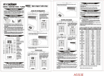
READ AND SAVE THESE INSTRUCTIONS
NOTE:
YLrlmml
1
CORPORATION
I.
INSTALLATION
AND
OPERATING
INSTRUCTIONS
The fan in the Microshelf
Hood turns on
automatically
to protect the microwave oven
when the temperature inside the hoodreaches
122°F (SO’C). It turns off automatically
when
the temperature falls below 95°F (35°C).
INSTALLATION
REQUIREMENTS
A. Space Requirements
A typical installation can be seen in Figure 1. Study
Figure 1 before proceeding. The Microshelf Hood
requires
an opening
that is 30” wide. It is
recommended that the cabinet above the cooktop
be a maximum of 15” high. This provides adequate
space between
the range cooktop
and the
Microshelf Hood.
FOR
MICROSHELF
HOOD
MODEL RJH 3330-l
l-
Before you begin, read the following
instructions
completely
and carefully. If followed, they will simplify
the installation
job.
CEILING
--(
APPROX
96”
FROM
FLOOR
%I
FURR
DOWN
F 3;‘.IO”
1
IMPORTANT:
OBSERVE ALL GOVERNING
AND ORDINANCES
CODES
TRANSITION
%
FLOOR
SAVE THESE INSTRUCTIONS
FOR THE LOCAL
ELECTRICAL
INSPECTOR’S
USE
BEFORE YOU USE YOUR MICROSHELF
DUCT
HOOD:
Be sure your Microshelf
Hood is installed
on an
appropriate wall strong enough tosupport this appliance.
NOTE:
The shelf of the Microshelf Hood is designed
to support a Microwave
Oven with a net
weight of up to 75 pounds.
The area used for the installation must be suitable forthe
size, function,
and protection
(from elements) of the
Microshelf Hood.
CAUTION:
When mounting the Microshelf Hood to a
wall, you must locate 2 studs in the wall.
Do not attempt to install the hood if the 2
wall studs are not found.
Be careful when drilling holes into a wall. Electrical wires
and water pipes may be concealed
behind the wall
covering.
tu
T
MICROWAVE
OVEN
SHELF1
n000
I5”MIN
DUCT
PROVIDED
WITH
HOOD
$
II
THICK
SHEET
COOK
ROCK
TOP?
Figure 1
B. Electrical Requirements
A 120 Volt, 60 Hz, AC only, 20 Ampere fused
electrical supply is required (time delay fuse or
circuit
breaker
is recommended).
It is
recommended
that a separate circuit serving only
this appliance be provided.
C. Venting Requirements
For vented installations,
the venting system must
terminate to the outside.
CAUTION:
Do not terminate the vent in an attic or
other enclosed space. This type of installation may
result in a fire.
APPROVED FOR USE WITH WHIRLPOOL
RJM
AND RHM SERIES AND THE RFM 7300-l
MICROWAVE OVENS.
If a vertical venting system is used, using 3%” x 10”
duct, the maximum length allowed is 25 feet. If
elbows are used in the venting system, reduce the
length of 3%” by 10” duct by 24 feet for each elbow
used.
The Microshelf Hood may be centered horizontally
as shown in Figure 2. The maximum length of duct
run horizontally,
using one 3%” x 10” elbow, is one
foot
APPROVED
FOR
USE
OVER
WHIRLPOOL
CONVENTIONAL
RANGE COOKTOPS
THAT DO
NOT HAVE A GRILLE.
Page 1
+“x
RAIN
If the Microshelf
Hood is to be installed
NOTE:
above a freestanding
range, disconnect the power
from the range and move the range out of the
opening in the cabinets. This will allow for more
access to the installation
area.
If installing the Microshelf Hood above a built-in
cooktop or set-in range, lay a protective cover over
the cooktop during the installation.
This may help
prevent damage to the cooktop (in case you drop
something)
and it will prevent dust and dirt from
accumulating
on the cooktop during installation.
IO”ELBOW
CAP
12” HIGH
CABINET
TRANSITION
DUCT
PROVIDED
WITH HOOD
3. Mark a line on the back wall 15” down from the
upper cabinets 30” long centered between theside
cabinets or allotted space. See Figure 3.
4. Locate the 2 wall studs in the area you have
selected for mounting the microwaveoven.
IF YOU
DO NOT KNOW HOW TO LOCATE A WALL
STUD,
CONSULT
A LOCAL
BUILDING
CONTRACTOR
FOR HELP.
If 2 studs are not located on the line drawn
NOTE:
in Figure 3, DO NOT attempt to install the shelf
hood.
SHELF/
HOOD
Figure 2
II.
VENTED INSTALLATION
For ventless
installation,
Kit RCH3630 must be
installed.
A. Assembling and Installing to Wall
1. Select the area for installation,
making sure
you have an electrical supply available. See the
shaded area in Figure 3. This is the area the
electrical supply must enter.
5. Line the top of the hanging bracket up with the
line drawn on the wall in Figure 3. Move the bracket
to the left or right within the allotted 30”space until
the center line of the 2 studs line up with 4 holes in
the hanging bracket. Neither edge of the bracket
should be closer than l/2” to the side cabinets or the
end of the 30” allotted space. (See Figure 4).
ELECTRICAL
INLET AREA \
ON BACK
6. Mark and drill four 3/16 dia. pilot holes in the
studs for the l/4” dia. x 2” long lag bolts provided.
CLEARANCE
TO CABINET
WALL
Figure 3
STUD+
1
-MARK
HANGING
*When installing the Microshelf Hood in a ventless
installation,
this dimension
is 16%“. See the
instructions
with the ventless kit (RCH3630) for
details.
HOLES-REMOVE
BRACKET
DRILL
&’
II
+ SHEET
DIA.
HOLE
AND
IN
ROCK
Figure 4
CAUTION:
Due to the amount of weight the
Microshelf
Hood must support, you must make
sure the Microshelf Hood is mounted to 2 vertical
wall studs and into the wall covering which must be
at least %” thick sheet rock, with 4 wall anchor
bolts.
2. If the Microshelf Hood is mounted to a wall that
does not meet the above recommendations,
the
weight of the microwave
oven may cause the
Microshelf
Hood to pull away from the wall
resulting in personal injury or property damage.
7. Mark 2 holes on each end of the hanging
bracket. Remove bracket and drill four 7/16” dia.
holes.
8. Insert four hollow wall anchor bolts into the
four 7/16” dia. holes in thesheet rock. Anchor bolts
are provided in installation
pack. Rotate anchor
bolts screws 5-10 revolutions to hold each anchor
bolt in place. These will be completely tightened
later. (See Figure 5).
Page 2
-
-;
14. Hang the shelf hood on the hanging bracket.
(See Figure 10). To be sure theshelf hood hanging
angle is completely
engaged
in the hanging
bracket, measure from the top of the shelf hood to
the top of the hanging bracket. This distance
should be l-7/16” on both ends.
THICK
SHEET
ROCK
SCREW,
2s’
NO. IO
CAUTION:
Do not continue
until both ends
measure l-7/16”. If the hanging angle is not fully
engaged in the hanging bracket, the Microshelf
Hood will not be level and the hood may become
dislodged from the hanging bracket. This could
cause damage.
15. Complete the duct work by:
A. Fit the duct provided with the Microshelf
Hood on to the vent outlet of the Microshelf
hood.
<.
U
HOLLOW
ANCHOR
WALL
BOLT
Figure 5
10. Attach hanging bracket to the wall with the
four screws taken from the anchor bolts. Tighten
the screws in the anchor bolts until the anchor
bolts are completely set.
B. Mark and drill (2) %” dia. holes (1 each
side) to fasten the thin duct provided with the
hood to the back wall. See Figure 7.
C. Use 2 #8 x VI” long screws provided with
the unit to fasten the narrow thin duct to the
shelf. See Figure 7.
11. Install four remaining
‘/4” dia. lag bolts
through the hanging bracket and into the two
studs.
Do not overtighten
the lag screws. If
CAUTION:
they are overtightened,
the bracket may pull into
the wall material which will not allow the shelf to
slide into place properly.
D. Next install the transition adaptor to the
thin duct.
This transition adaptor will accept 3%” x 10”
duct.
E. Complete
the 3%” x 10” duct (or
equivalent)
to the outside
using
the
guidelines listed under venting requirements.
9.
Remove all 4 screws from the anchor
bolts.
12. The hole in the bottom of the cabinet (for the
duct provided with the hood) should be cut as
shown in Figure 6 (15%” long by 1%” deep). Hole
must be cut to back wall. Make sure to center the
hole within the 30” allotted space.
L
HANGING
BRACKET
B. Connect the electrical supply:
It is the personal responsibility
and obligation of the
customer to contact a qualified installer to assure that
the electrical
installation
is adequate
and is in
conformance
with the National Electrical Code and
local codes and ordinances.
Figure 6
13. Rough wire the electrical
shown in Figure 3.
supply
to the area
Page 3
1. Connect the appliance to the junction
box
through
flexible
armoured
or nonmetallic
sheathed
copper cable (with ground wire). A
suitable strain relief must be provided at each end
of the power supply cable (at appliance and at the
junction box). See Figure 8.
*Cold water pipe must have metal continuity
to
electrical ground and not be interrupted by plastic,
rubber or other electrically
insulating connectors
(including water meter or pump) without adding a
jumper wire to these connections.
C. INSTALLING
AND
LEVELING
THE
MICROWAVE OVEN.
1. Remove the screw from the upper left
hand side of the microwave oven. See Figure
9.
2. Screw the safety bracket to the back of the
microwave
with the screw removed in the
previous step.
2. This appliance is equipped with copper lead
wires. If connection
is made to aluminum house
wiring, use only special connectors
which are
approved for joining copper and aluminum wires
in accordance
with the National Electrical Code
and local codes and ordinances.
Electrical
Ground
is Required on This Appliance
Recommended
Electrical Connection
and Groundrng Method
This appliance must be permanently grounded in
accordance with the National Electrical Code and
local codes and ordinances.
TO 20 AMP
FUSED
DISCONNECT
(WIRING
DONE
ACCORDING
TO
NATIONAL
ELECTRICAL
CODE
AND
APPLICABLE
LOCAL
CODES)
RECEPTACLE7
SCREW REMOVED FROM
/
__
H
CONNECTION)
Figure 9
LEADING
SWITCHES
I
I
\GROUND
SCREW
I
TO
3. Place the empty hood carton the top of the
cooktop. Test the shelf hood for strength. If
the mounting seems secure, proceed to the
next step.
4. WARNING:
THE WEIGHT
OF THE
MICROWAVE
OVEN MAY EXCEED YOUR
WE RECOMMEND
LIFTING
ABILITY.
ASSISTANCE.
I
I
I
TERMINAL
ACCESS
COVER
\yy##y-F
Figure 8
1. Remove the terminal access cover. See Fig. 8.
2. Install a strain relief into the opening of the
wire junction box. See Figure 8.
3. Connect the white and black wires of the
power supply cable to the white and black wire
leads inside the terminal access box. See Figure 8.
4. Connect the green ground wire from the power
supply cable to the end of the green ground wire
provided in the terminal access box. See Figure 8.
5. Replace the terminal access cover.
Alternate Grounding
Method
If the recommended
grounding
method
is
impossible,
permanently
ground the appliance
from the green ground wire (located in the terminal
access box) to a grounded cold water pipe* using a
separate,
green
colored,
insulated
copper
conductor
of appropriate size (no. 16 minimum).
THIS, HOWEVER, IS NOT RECOMMENDED.
Do
not ground to a gas supply pipe. Do not connect to
electrical supply until appliance is permanently
grounded.
I
7 I(
‘Is
SHELF
HOOD
HANGING ANGLE
\
SHELF
HOOD
BACK
LEVELING
BOLTS
Figure 10
Page 4
w
Place
right
right
front
the microwave oven on the hood shelf on the
hand side of the hood aligning the front and
hand side of the microwave oven with the
and right hand side of the Microshelf Hood.
Place the microwave oven on the hood shelf on the
left hand side. Plug the microwave oven into the
outlet provided in the top of the shelf hood.
Slide the microwave oven to the right so the right
hand side of the microwave oven is aligned with
the right hand side of the hood shelf. Install the
safety bracket using the safety bracket retaining
screw. Before operating
the microwave
oven,
make sure the oven cavity and magnetron area
cooling vents will not be restricted.
Use the leveling bolts provided to level shelf hood
after weight of the appliance is placed on it. Bolts
are provided in the installation package. Screw the
bolts into the nuts provided on the lower left and
right hand sides of the shelf hood until the unit is
level. See Figure 10.
NOTE:
The leveling
8. Insert Glass
Figure 11.
bolts have a g/16” hex head.
Frame Assembly
according
to
CAUTION:
THE MICROWAVE OVEN MUST BE
LEVEL FROM FRONT TO BACK TO MINIMIZE
UTENSILS
FROM SLIDING
FORWARD WHEN
OPENING THE DOOR.
5. Mark the safety bracket hole on the back wall
through
the center of the slotted hole in the
bracket, so it can be attached to the rear wall.
WARNING:
THE WEIGHT OF THE MICROWAVE
MAY EXCEED YOUR LIFT:NG
ABILITY.
WE
RECOMMEND
ASSISTANCE.
6. Remove the microwave oven and drill a 3/16
dia. hole through the back wall in the location
marked in step 5 above. If a solid wood stud is
behind the wall covering, a l/4” dia. lag bolt will be
used to mount the safety bracket to the wall. If no
solid stud is found in this location, drill a 7/16 inch
dia. hole in the wall and insert a hollow wall
expanding anchor bolt.
7. WARNING:
THE
WEIGHT
OF THE
MICROWAVE
MAY EXCEED YOUR LIFTING
ABILITY. WE RECOMMEND
ASSISTANCE.
OPERATION
Figure 11
AND CARE OF UNIT
CARE OF FILTERS:
A. ALUMINUM
FILER:
For greatest efficiency,
the permanent
type aluminum
filter should be
removed and cleaned periodically.
LIGHTS:
Select two light bulbs up to 60 watts each to
achieve desired lighting for cooking. The three
position switch provides two levels of lighting.
CARE OF EXTERIOR SURFACES:
Clean with a mild detergent to preserve finish. DO
NOT use abrasive cleaners.
TO CLEAN:
The filter should be soaked in hot
water and detergent, then thoroughly
rinsed. The
aluminum filter can be cleaned in a dishwasher.
Replacement
filters and repair parts may be
obtained
from Whirlpool
Corporation,
Parts
Distribution
Center, LaPorte, Indiana 46350.
CAUTION:
Operate the hood only with the filter
in place to prevent grease build up inside the hood.
Page 5
Whirlpool
franchised
TECH-CARE@
service
If your WHIRLPOOL appliance ever needs serviceanywhere
in the United States, help is just a phone call away.
.to your
nearest TECH-CARE
service representative.
Whrrlpool
maintains
a nationwide
network of franchised
TECH-CARE
servrce companies
to fulfill your warranty
and
provide after-warranty
service and maintenance
to keep your
WHIRLPOOL
appliance in peak condition.
You’ll find your nearest TECH-CARE servicecompany
listed
in your
local
telephone
book
Yellow
Pages
under
Washers/Dryers-Repairing
or Servicing. Should you not find a
listing, dral free, the Whirlpool COOL-LINE@ servrce assistance
telephone number (800)253-1301. When calling from:
Mrchigan
Dial (800) 632-2243
Alaska& Hawaii..
_.
Dial (800) 253-l 121
My TECH-CARE
service
representative’s
telephone
number
is:
Range hood model number.
Range hood serial number:
Purchase
and/or
installation
date:
If you move..
Call the TECH-CARE
service representative
in your local
area. He’ll see to the installation
of WHIRLPOOL
appliances in
your new home. promptly, expertly and fairly priced to you.
~irlpool
Helptul hints. .
You can help your TECH-CARE
service representative
give
you faster service if you include the model and serial number of
your appliance when requesting service. Also, retain your sales
slrp and warranty to verify your warranty status.
CORPORATION
Benlon Harbor, Mlchlgan. Automatrc Washers,
Clothes Dryers, Freezers, Refngerator-Freezers,
Remember.
Your TECH-CARE service representative
is specially lrained
in the expert repairing
and servicing
of your WHIRLPOOL
appliances. He can help you maintain the quality originally built
into your WHIRLPOOL appliance. So why not take the trme, now,
to look up his telephone number and fat it down in the space
provrded below.
Ice Makers, DIshwashers.
Built-In Ovens and
Surface Units, Ranges, MIcrowave
Ovens, Food
Waste
Drsposers.
Compactors,
Conditioners,
Dehumidifiers,
Air Conditioning
Systems
l-27-81
A625-964
Page 6
Room
Air
Central Heating and
PART
NO. 830806A