1
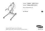
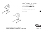
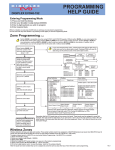
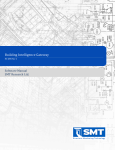
RESIDENTIAL
PLATFORM LIFTS
RPL400 / RPL600
Installation and
Service Manual
WARNING! STRICT ADHERENCE TO THESE INSTALLATION INSTRUCTIONS IS REQUIRED to promote the safety of those installing
this product, as well as that of those ultimately using the lift for its intended purpose. Any deviation from these instructions will
void the Limited Warranty that accompanies the product. Additionally, any party installing the product who deviates from the
Installation Instructions shall be taken to agree to INDEMNIFY, SAVE AND HOLD HARMLESS the manufacturer from any and all
loss, liability or damage, including attorney fees that might arise out of, or in connection with, such deviation.
Table of Contents
This Installation and Service Manual provides step-by-step instructions on how to install a
Highlander Residential Platform Lift. Read and understand the entire Manual before beginning
to install the lift. Also, ensure that the end-user has a copy of the Owner’s Manual with
operating instructions before it is put into service.
If you have questions, concerns or comments, please contact Harmar’s Technical Service
Department at 1-866-378-6648 or email [email protected].
CONTENTS
Features...............................................................................................3
Specifications......................................................................................3
Safety & Code Requirements...........................................................4
Site Requirements.......................................................................4
Preliminary Checks............................................................................5
Review All Parts...........................................................................5
Tools Needed...............................................................................5
Materials Needed........................................................................5
Preparing to Install............................................................................6
Installing the Platform......................................................................7
Controller Harness Connections...............................................8
Installing Outer Guard Panel.........................................................10
Installing the Ramp.........................................................................11
Top Landing Gate (Optional)..................................................12
Top Landing EMI Interlock (Optional)...................................13
Fascia Panel (Optional)............................................................14
Anchoring the Lift............................................................................15
Setting the Limit Switches..............................................................17
Verifying Lift Operation..................................................................18
Manual Override..............................................................................19
2
RPL Installation and Service Manual |
| www.Harmar.com | 866-351-2776
Features
Top Cover
Data / Serial Tag
Ramp Roller Guide
Platform
Controls
Platform
Front Guard
Panel
Platform
Rear Guard
Panel
Platform Assembly
Safety Pan Assembly
Folding Ramp
SPECIFICATIONS
Payload Capacity: Vertical Travel Height: RPL400:
RPL600:
Footprint: 600 lbs.
53”
77”
50” x 73”
36” x 48”
115VAC - 15a grounded circuit
24VAC
10 ft/min.
½ HP - 90 VDC
Platform: Input Voltage: Control Voltage: Platform Speed: Motor: RPL Installation and Service Manual |
| www.Harmar.com | 866-351-2776
3
Safety
Read all instructions in this Manual before installing or operating the lift.
• Always wear eye protection while installing or servicing this product.
• Always disconnect this product from the electrical source before servicing it.
• Do not wear loose clothing or jewelry when working on this product.
• Do not disable any safety equipment or switches supplied with this lift.
• Stay away from all drive train components while the lift is operating.
• Do not exceed the maximum payload capacity of 600 lbs.
• Do not ride on the lift until it is anchored in place.
• This product is designed only for lifting people and mobility devices. Do not use for any other purpose.
Code Requirements
This lift is designed to meet ASME A18.1 section 5 and CSA B44/ASME A17.5 with the addition of
certain options. Code requirements for vertical platform lifts vary depending on location. Installers are
responsible for contacting their local code enforcement office to determine all applicable regulations
prior to installing vertical platform lifts.
Site Requirements
• The lift requires a 115VAC 20 amp grounded circuit.
• Outdoor installations require a GFI protected circuit.
• Only install the lift on a 4” thick, level 3,500 psi reinforced concrete slab.
• Footprint requires 49” x 69” area (this includes the folding access ramp.)
4
RPL Installation and Service Manual |
| www.Harmar.com | 866-351-2776
Preliminary Checks
Review All Parts
• Check the lift for shipping damage. If you find any damage contact the freight carrier to file a damage claim.
• Verify the products match that described on the packing list attached to the exterior packaging.
Tools Needed
• ½” Hammer Drill
• 3/8” Masonry Drill Bit
• Appliance Dolly
• Hammer
• Level
• Measuring Tape
• Socket Wrench Set
• Screwdriver Set
• Allen Wrench Set
Materials Needed
• 4 Floor Anchors
Harmar recommends securing the lift using our anchor kit. If you purchase your own floor anchors they must use
3/8” bolts and have a minimum tensile strength of 6,000 lbs.
RPL Installation and Service Manual |
| www.Harmar.com | 866-351-2776
5
Preparing to Install
Final Site Inspection
Verify the surface of the lift will mount to is smooth and level. This surface must be made from 3,500 psi
reinforced concrete with a minimum thickness of 4.”
Verify that there is enough space for the lift’s footprint. Include space for the folding access ramp, allowing
50” x 70.”
CAUTION: Verify that the running clearance around the lift complies with any codes for your area.
• The horizontal gap between the edge of the platform and the upper landing must be no less than 3/8”
and no greater than ¾.”
• The horizontal gap between the guard panel and any wall or barrier must be no less than 2” and no
greater than 3.”
• The ASME A18.1 Code recommends that a gate or door be installed at the upper landing.
• Verify that sufficient head room exists above the lift. The lift will require 6’8” of clearance above
the platform floor when the lift is at the upper landing.
WARNING: The area between the floor where the lift is mounted and the top landing must be
covered by a smooth vertical fascia to eliminate pinch points between the platform and landing.
Connecting Electricity
The lift requires a 115VAC 15 AMP grounded, dedicated electrical outlet within 6 feet of the lift. Plug the lift
directly into the power outlet. Do not plug anything else into the same outlet as the lift.
WARNING: Do not ride on the lift until it has been anchored in place.
6
RPL Installation and Service Manual |
| www.Harmar.com | 866-351-2776
Installing the Platform
Step 1
The lift will arrive on its back on a pallet. Carefully
cut away and remove the shrink wrap to expose the
platform, guard panels, ramp, and lift tower.
Step 2
Unpack the platform, guard panels, ramp and smaller
hardware box from the lift tower. The mounting bolds,
nuts an spacers that secure the platform to the lift
carriage are included in the small hardware pack.
Step 3
Carefully tilt the lift tower up and remove from the pallet. Remove
the top cover and the front panel from the lift tower by removing
the three Phillips head screws at the top. Set the top cover aside.
Grasp the loose panel by its sides and raise it up and
slide it to the side, freeing it from the lift frame.
Step 4
Plug the platform control box into the Controller Harness
that exits the plastic chain on the left tower.
Plug lift tower into power source and, using the
rocker switch on the platform control box, carefully
lower the platform carriage to the ground.
Note: If the red emergency stop button on the front of the control
box is pushed in the lift will not move. Grasp the red button
and pull it straight out to disengage the emergency stop.
RPL Installation and Service Manual |
| www.Harmar.com | 866-351-2776
7
Verify the surface the lift will mount to is smooth and level. This surface must be made from 3,500 psi
reinforced concrete with a minimum thickness of 4”.
Verify that there is enough space for the lifts foot print. Be sure to include space for the folding access
ramp. (49” xthe
69”) Platform (con’t)
Installing
Caution: Verify that the running clearance around the lift complies with
any codes for your area.
The horizontal gap between the edge of the platform and the upper landing must no less than 3/8”
and no greater than 3/4”.
• The horizontal gap between the guard panel and any wall or barrier must be no less than 2” and
no greater
3”.
Controller
Harnessthan
Connections
• It is recommended that a gate or door be installed at the upper landing.
• Verify that sufficient head room exists above the lift. The lift will require 6ʼ 8” of clearance above
the platform floor when the lift isFigure
at the1 upper landing.
Figure 2
•
Warning: The area between the floor where the lift is mounted and the top
landing must be covered by a smooth vertical fascia. This is to to eliminate any pinch
points between the platform and landing.
Connecting to Electricity
The lift will require a 115 VAC 20 amp grounded electrical outlet within 6 feet of the lift.
Plug the lift directly into the power outlet. Do not plug anything else into same outlet as the lift.
Warning: Do not ride on the lift until it has been anchored in place.
Controller Harness Connections
High Voltage Circuit Breaker (AC unit only) Upper & Lower Call‐Sends Low Voltage Circuit Breaker Safety Pan Jumper
Platform Traveling Cable
Upper & Lower Limit Switches
Figure 3
Upper Landing Interlock
Note: Lift will be shipped with jumper in place.
8
RPL Installation and Service Manual |
| www.Harmar.com | 866-351-2776
Installing the Platform (con’t)
Step 5
Align the four platform mounting holes with those on the lift carriage.
Insert a ½” x 3” bolt into each of the lower holes. Place the spacers
between the carriage flanges and the platform arm upper holes and
insert ½” x 3” bolts. Install the low-profile lock nuts on the upper bolts
and the standard ones on the lower bolts.
Step 6
Locate the safety pan harness exiting from the rear of the platform
and plug it into the harness at the end of the plastic chain in the lift
tower. Secure the platform control harness and the safety harness
under the clip at the top of the carriage flange.
Step 7
Remove the safety pan bypass jumper from the front of the electronics
box at the top of the lift. Verify that the platform safety pan is
operational by pressing up on the pan when the lift is coming down.
The lift should stop but be able to move in the up direction.
RPL Installation and Service Manual |
| www.Harmar.com | 866-351-2776
9
Installing the Outer Guard Panel
Step 1
Remove the outer hex bolts on the ends of the platform. Insert the guard
panel posts in the pockets in the platform. The smooth side of the guard
panel should face in towards the center of the platform. Bolt in place. If
you have a 90 degree exit platform, install the end guard panel using the
provided bracket and bolt to inner guard panel.
Step 2
Install the platform control box on the rear guard panel using screws and
nuts through the panel.
Step 3
Install rear panel on platform by installing guard panel posts into the
pockets at the rear of the platform and bolt in place.
Step 4
Install platform control box to rear guard panel.
10
RPL Installation and Service Manual |
| www.Harmar.com | 866-351-2776
Installing the Ramp
Step 1
Install the ramp roller guide on the side of the lift tower using the screws
already installed in the panels.
Note: The longer flange will point toward the floor.
Step 2
Attach the two ramp pivot tabs to the lower landing sides of the
platform. Reinsert the hex bolts, one of which will go through the guard
panel post, and tighten.
Step 3
Attach the ramp to the pivot tabs using shoulder bolts and locking nuts.
Tighten the nuts until they seat against the bolt shoulder.
Step 4
Attach the ramp roller arm by bolting it to the underside of the ramp.
The ramp roller should align and make contact with the ramp roller
guide. The roller should ride up the tower arm, folding the ramp when
the platform is raised.
RPL Installation and Service Manual |
| www.Harmar.com | 866-351-2776
11
Top Landing Gate (Optional)
Top Landing Gate (optional)
The optional top landing gate is provided with a combination
mechanical lock and electric contact (interlock.)
The interlock:
• Prevents the lift from running if the gate is open.
• Prevents the gate from being opened if the platform is not at
the top landing.
• Unlocks when the lift is on the upper limit switch.
Wiring
A length of multi-conductor wire will
need to be run from the bottom of
the lift tower up to the landing gate.
Consult local codes for type and
mounting requirements. After wiring
is completed, the wiring harness
must be plugged into an appropriate
receptacle on the controller.
Wiring Connections
A crescent-shaped key is provided to manually unlock the gate
during installation. The key is inserted from the back side to lift
up on the solenoid that holds the gate locked.
Gate Harness
Black
Black
Yellow
Yellow
Gate Harness
Orange
Green
Black
Brown
Call-Send Harness
Blue
Yellow
Red
Lift Harness
Blue
White
Red
Mount the gate by placing onto the upper landing making
sure to align the gate opening with the platform (outer guard
rail not shown for clarity.) A number of attachment holes are
provided in the threshold portion of the gate for mounting
using wood lag screws or concrete anchors as appropriate.
Remove the latch post cover and connect the call-send and
interlock wire harnesses.
The vertical posts of the gate must be attached to a supporting
structure. The gate is not designed to be freestanding.
12
RPL Installation and Service Manual |
| www.Harmar.com | 866-351-2776
Top Landing EMI Interlock (Optional)
Top Landing EMI Interlock (optional)
The optional EMI Interlock is provided with a combination
mechanical lock and electric contact. They are to be used with
existing doors.
The interlock:
• Prevents the lift from running if the gate is open.
• Prevents the door from being opened if the platform is not at
the top landing.
• Unlocks when the lift is on the landing limit switch.
EMI Interlock
1. Position interlock to door jamb and mark mounting holes
2. Fasten interlock to door jamb with #8 wood screws.
3. Route 4-conductor interlock cable thru hole in top of interlock
and make wire connections.
4. Attach door keeper and emergency key plates to hoistway door.
RPL Installation and Service Manual |
Wiring
A length of multi-conductor wire
will need to be run from the bottom
of the lift tower up to the interlock.
Consult local codes for type and
mounting requirements. After wiring
is completed, the wiring harness
must be plugged into an appropriate
receptacle on the controller.
Wiring Connections
EMI
Black (A)
Black (B)
Yellow (C)
Yellow (D)
Lift Harness
Orange
Green
Black
Brown
| www.Harmar.com | 866-351-2776
13
Fascia Panel (Optional)
Fascia Panel (optional)
A fascia panel must be used. It provides a smooth surface
for the platform edge to meet in order to prevent any shear
or obstruction hazards.
A running clearance of no more than ¾” and no less than
3/8” must be maintain between the edge of the platform
and the fascia panel.
14
RPL Installation and Service Manual |
| www.Harmar.com | 866-351-2776
anchors they must use 1/2-13 bolts and have
a minimum tensile strength of 6000 LBS.
Warning: All four floor anchors
Anchoring
must be installed
correctlythe
in Lift
accordance to
their instructions.
Step 2
Use the liftʼs base as a template. Drill 4 holes
into the concrete.
Step 1
• Position the lift in its final location
• Verify that it is level and perpendicular to its surroundings.
• Shim if necessary.
9
CAUTION: Verify that the running clearance around the lift
complies with any codes for your area. The horizontal gap
between the edge of the platform and the upper landing must
be no less than 3/8” and no greater than 3/4.”
Anchoring the Lift
The horizontal gap between the guard panel and any wall
or barrier must be no less than 2” and no greater than 3.”
Step 1
• Position the lift in its final location.
• Verify
it is or
level
and be
perpendicular
It is recommended
that that
a gate
door
installed atto its
surroundings.
the upper landing.
• Shim if necessary.
Anchors
Harmar
recommends
securing
using
Verify that sufficient
head
room exists
abovethe
theliftlift.
The lift
our Anchor Kit. If you purchase you own floor
requires 6’8” of clearance
above
floor
anchors they
mustthe
useplatform
1/2-13 bolts
andwhen
have the lift is
a minimum tensile strength of 6000 LBS.
at the upper landing.
Warning: All four floor anchors
must
be installed
Warning: The area
between
the floorcorrectly
where theinlift is
to be covered by a
mounted and theaccordance
top landing must
their instructions.
Verify
the holes and
you have
drilled are
smooth vertical fascia. This is to eliminate any pinch points between
thethatplatform
landing.
deep enough to accept the anchors.
Step 2
Use the liftʼs base as a template. Drill 4 holes
into the concrete.
Tip: Concrete dust may have settled into
the holes you just drilled. Use a shop
vacuum to clean out these holes. This will
ensure the floor anchors set correctly.
Step 3
Secure the lift in place by tightening the floor
anchor bolts.
RPL Installation and Service Manual |
| www.Harmar.com | 866-351-2776
15
Anchoring the Lift (con’t)
Anchors
Harmar recommends securing the lift using our Anchor Kit. If you purchase your own floor anchors they
must use 3/8” bolts with a minimum tensile strength of 6,000 lbs.
Warning: All floor anchors must be installed correctly in accordance to their instructions.
Step 2
Use the lift’s base as a template. Drill 4 holes into the concrete. Verify that holes you have drilled are deep
enough to accept the anchors.
TIP: Concrete dust may have settled into the holes you just drilled. Use a shop vacuum to clean out
these holes. This will ensure the floor anchors set correctly.
Step 3
Secure the lift in place by tightening the floor anchor bolts.
16
RPL Installation and Service Manual |
| www.Harmar.com | 866-351-2776
Verify the emergency switch is in the ON
landing.Run
Thethe
lower
limit
position.
lift in
thewill
up typically
directionno
u
the platform floor is level with the upper
Step 1
landing.
Setting
the
Switches
Verify
theLimit
emergency
switch is in the O
position.
Run
the
lift
in
up from
direction
1A Unplug the liftʼs powerthe
cord
the
the
platform
floor
is
level
with
theunits).
uppe
before going to the next step (AC
landing.
1A Unplug the liftʼs power cord from th
before going to the next step (AC units
This lift is equipped with upper and lower limit switches. The vertical
location of these switches may be adjusted to fit your application.
Typically, the upper limit switch will need to be adjusted so the platform
will stop level with the upper landing. The lower limit will typically not need
adjusting.
Step 1
Verify the emergency switch is in the ON position. Run the lift in the up
direction until the platform floor is level with the upper landing.
Step 2
Unplug the lift’s power cord from the wall before going to the next step (AC
units) Unplug the power cable from the battery box before going to the next
step; (DC units)
1B Uplug the power cable from the batte
box before going to the next step (DC un
1B Uplug the power cable from the bat
box before going to the next step (DC u
WARNING: Moving components can cut and crush. Do not operate the
lift if you are in close proximity to any drive components. Be aware that
loose clothing or jewelry may catch on moving parts.
Warning: Moving components can cu
and crush. Do not operate the lift if yo
are in close proximity to any drive
components. Be aware that loose
Warning:
components
clothing
or Moving
jewelry may
catch oncan
movc
and
crush.
Do
not
operate
the
lift
if y
parts.
Step 3
are in close proximity to any drive
Remove the front cover by tilting it forward and lifting upwards. The bottom components. Be aware that loose
of the front cover sets on a pin on either side of the lift frame. Set the cover
clothing or jewelry may catch on mo
parts.
aside in a safe location where it will not become damaged.
Step 4
Loosen the bolts that attaches the upper limit switch assembly. Slide the
assembly down the track until the lower switch in the assembly comes in
contact with the stop bracket on the lift’s car. You should hear the limit
switch click as contact is made.
RPL Installation and Service Manual |
| www.Harmar.com | 866-351-2776
17
Verifying Lift Operation
Step 5
Replace the front cover and secure it with the screw you removed in Step 1.
Step 6
Plug the lift’s electrical cord into the wall. Verify that the emergency switch is in the ON position.
Step 7
Run the lift in the down direction for several inches. Next, run the lift in the up direction. Continue to press
the up button until the upper limit switch has caused the lift to stop. Be sure the lift platform stops level with
the landing platform.
VERIFYING LIFT OPERATION
CAUTION: Complete the following section before training the customer to use the lift.
Step 1
Run the lift up and down for 5 complete cycles. Hold the direction button down and allow the limit switches
to stop the lift. At the top, verify that the platform stops level with the upper
landing. At the bottom, verify the access ramp unfolds and rests on the ground.
Step 2
Verify the Emergency Stop Switch operation. When Emergency Stop is pushed, the
lift should not run in either direction. When the switch is pulled back out, the lift
should operate normally.
Step 3
Verify the operation of the sensor pan underneath the platform. Start with the lift
at the top landing. Press up on the sensor pan. While holding the pan in this location, press the down switch
on the platform. The lift should not run. Check all sides and middle of the safety pan.
18
RPL Installation and Service Manual |
| www.Harmar.com | 866-351-2776
Manual Override
In case of power failure, this lift is equipped with a Manual Override Crank that permits it to be raised or
lowered by hand. Before using, check to ensure that the manual system is required.
Verify the Need for Manual Override
Before using the Manual Override Crank, try trouble-shooting by verifying the following:
• Check that the Emergency Stop Switch is pulled out.
• Check that the electrical cord is plugged into the wall.
• Check that the building’s circuit breaker has not tripped.
• Try to run the lift by pushing both the up and down buttons.
Manual Override Procedure
If, after Troubleshooting as above, the lift still will not run, complete the following steps:
Step 1
Unplug the lift from the wall. Push in the Emergency Stop Button.
WARNING: Do not service or operate the Manual Override Crank while the lift is connected to
electricity.
Step 2
Loosen the screws and remove the top cap at the top of the tower.
Step 3
Insert the manual hand crank onto the upper nut on the top of the drive screw.
Rotate the crank to raise or lower the platform.
WARNING: Never operate the lift while the Manual Override Crank is inserted into the lift.
For your safety and that of the end-user, if you have any questions about installation or service procedures,
please contact Harmar’s Technical Service Department at 1-866-378-6648 or email [email protected].
© 2012 Harmar MKT-IM-HIGHLANDER-1214
RPL Installation and Service Manual |
| www.Harmar.com | 866-351-2776
19