1
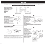
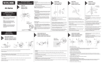
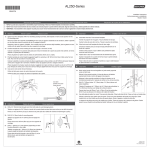
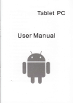
AL-Series Service Manual
Disassemble Trim From Lock
1. Place a narrow tool into hole in inside lever
to depress catch. Remove lever and driver.
Repeat for outside lever and driver.
2. Rotate inside rose counterclockwise to
remove from spring cage.
3. Using provided wrench, unscrew inside and
outside castlenut bushings. Using Phillips
screw driver, unscrew through bolts.
Remove inside spring cage, anchor spring
and outside rose and spring cage assembly.
Disassemble Chassis
4. Remove chassis screws. Straighten lugs and
remove housing from chassis.
(If necessary, rap on edge of housing to
loosen assembly.)
5. Depress slide, unhook and remove inside
plunger and spindle.
6. (Hold palms of hands around lock to prevent
springs from escaping from slide.) Press
forward with thumbs against frame tabs
while pushing upward with index finger to
disengage hub plate.
7. Remove slide and springs.
8. Remove cam from outside spindle.
9. Use pliers to snap off outside button from
plunger bar. Now remove the plunger bar.
10. To remove outside spindle, depress catch
and push slide into hub and frame as far as it
will go. Rotate spindle until catch aligns with
slot in hub and plate. Depress catch again.
Remove spindle.
Outside Button and Bar Assembly
11. Insert outside spindle through lock frame from
inside of frame. Insert plunger bar (less button
assembly) into spindle as shown. The bar will
stop against the catch in the spindle.
Insert cam into
spindle. The bar
will become
trapped in the spindle
by the cam. Reposition hub
plate, slide and springs in frame.
Follow previous steps 1 thru 5 for disassembly
of trim and chassis.
To remove outside lever of keyed functions,
insert key into cylinder. Insert narrow tool into
hole in lever. Turn key 90° and depress catch
with tool. Pull off lever.
8. Align plunger button assembly so lug fits
into slot on spindle. Position plunger
button assembly onto bar and snap firmly
into place.
9. Reverse steps to reassemble completelock and trim.
6. Insert new plunger bar (less button
assembly), depress slide and push plunger
bar while releasing slide to hook into place.
12. Install button assembly into spindle and snap
firmly onto plunger bar. When properly
assembled, rotating button will retract the slide.
13. Reverse steps to reassemble chassis and
lock trim.
7. Install spindle over bar, rotate slightly and
push into place. Slot on spindle should be on
same side as slide jaws.
NOTE: Accurate door preparation is essential for proper functioning of this lock. Follow template and instructions carefully.
DOOR AND JAMB PREPARATION
Install strike
a. Mark vertical line and heightline on
jamb exactly opposite center of
latch hole.
Mark door
a. Detach stub.
b. Fold template at correct marking for door bevel (high or low bevel, or flat).
c. Position template at correct height (suggested height for centerline is 38"
(97mm) from floor). Mark center for lock hole. Also mark for (2) holes for
mounting screws.
d. Use stub to mark center of door thickness.
1" (25mm) Hole,
³⁄₄" (19mm) deep
b. Drill (2) 1" (25mm) holes, ³⁄₄" (19mm)
deep, ⁵⁄₁₆" (8mm) above and below
heightline.
⁵⁄₁₆" (8mm)
c. Use strike plate to pattern for
cutout. Clean out hole and
install strike.
CL
HINT: For retrofitting existing lock holes, fold template in half to locate position
for the (2) mounting screws.
CL
C
LA L
TC
P50
INT
9-8
ED
63
IN
U.S
DETACH HERE
R FOR
CENTE
MARK
HOLE
¹⁄₈" (3mm)
ONLY
INSIDE
TE FOR
TEMPLA NG
INSTALLI
®
LEVER
D25D
LOCKS
)
2³⁄₄" (70mm
R
CENTE
MARK
HOLES
(54mm)
FOR 2¹⁄₈"
BACKSET
CL
LATCH
NT
IMPORTA
OUTSIDE
PLACE
BEVEL
DOOR
FOR HIGH AT EDGE OF
CENTER
PLACE
LINE
DOORS
DOOR
FOR FLAT AT EDGE OF
INSIDE
LINE
PLACE
BEVEL
DOOR
FOR LOWAT EDGE OF
LINE
H
PR
LOW
BEVEL
Door bevel
CEMAR
NT K
ER
DO OF
FO THIC OR
R 1" KN
(25 ESS
HO mm)
C
LE DIA.
L
⁵⁄₁₆" (8mm)
R FOR
CENTE
MARK
HOLE
¹⁄₈" (3mm)
ONLY
INSIDE
.A.
LOCK INSTALLATION
Disassemble inside trim
a. Insert pointed end of spanner wrench into hole in inside lever. Push to
depress catch and remove lever. Also remove driver.
2
Drill (4) holes
a. Drill a 2¹⁄₈" (54mm) hole through door (from both sides to avoid damaging
door).
b. Unscrew and remove castlenut bushing. (Use metal tool or plastic tool
provided.)
b. Drill (2) ⁵⁄₁₆" (8mm) holes for mounting screws.
c. Remove spring cage.
c. Drill a 1" (25mm) or ⁷⁄₈" (22mm) (depending on latch housing diameter) in door
edge.
a.
b.
c.
a.
b.
Install latch
a. Insert latch into hole. Trace around faceplate.
b. Chisel out wood until faceplate fits flat with door edge.
c. Fasten latch to door so that beveled side of latchbolt faces jamb.
c.
Install outside lock unit
Install inside rose
IMPORTANT: This lock is factory preset for 1³⁄₄" (44mm) doors. See other side to
center chassis in door or to change adjustment for other door thicknesses.
Align dimples on rose with grooves in
spring cage. Place rose against door and
rotate clockwise until dimples snap into
slots next to the grooves.
Place outside lock unit into position. Make sure that latch prongs engage chassis
housing, and latch retracter engages latch bar.
Install lever, insert, and driver
Engage prongs
a. Remove driver from lever and install it onto spindle.
b. Assemble plastic insert into lever. (CAUTION: Insert must be used for lock to
function properly.)
c. Slide lever and insert onto spindle. Push lever completely into place. (Pull on
lever to make sure that catch is fully engaged.)
b.
a.
Insert
Driver
Lever
Install inside assembly
c.
a. Hold outside unit in place.
b. Put spring cage into position on chassis.
c. Place castlenut bushing on threads of chassis. Hold outside lever in position
while threading castlenut. You will hear a ratcheting sound. Continue tightening castlenut with tool until lock is fastened firmly.
d. Insert and tighten mounting screws.
e. Retighten castlenut with installation tool.
CAUTION: When using power screwdriver for installation, set to minimum torque
setting
a.
Test operation of lock to make sure you have followed instructions correctly.
INTERCHANGEABLE CORE
How to remove core
Insert control key and turn it clockwise 15 degrees until action stops. Pull on key
to remove core.
b.
15˚
How to replace core
c.
d.
Insert control key fully. Push core into lever as far as it will go.
Turn key clockwise 15 degrees and push core completely into lever. Turn key
back to normal position and remove from core.
HOW TO ADJUST FOR NON STANDARD DOOR THICKNESS
Adjust for door thickness
Use tool to rotate castlenut bushing until screw post lines up with correct door
thickness mark.
Remove outside lever
a. Non-keyed locks (except A40S; See
step 2.)
Place pointed end of spanner
wrench into hole in lever. Push in to
depress catch and remove lever
and driver.
a.
b. Keyed Locks (Use screwdriver
instead of key for A40S locks.)
b.
HINT: It is easier to remove a keyed
lever if the lock is positioned in the
door cutout.
Insert key into cylinder. Insert pointed
end of spanner wrench (or similar tool)
into hole in lever. Turn key one-quarter
turn and push wrench to depress catch.
Reassemble outside lever
Reverse Step 10 to reassemble levers.
Install Interchangeable Core
Driver and Retainer
Installation Tool
(Order Separately)
e
c
b
2
Place retainer and driver on end of
installation tool as shown. Be sure
the flat sides of the retainer are
aligned as shown. Install the driver
so the timing line is horizontal, or parallel with the
latch. Insert installation tool into spindle and push in until it
stops. Remove installation tool.
3
AL-Series Kit:
a. Interchangeable
Core
b. Lever
c. Insert
d. Retainer
e. Driver
a
d
1
Install Interchangeable
Core Lever
a. Press insert into back of the lever
as shown. Be sure the insert is
firmly seated.
a.
b. Slide lever onto spindle up to catch.
Insert smooth end of installation
tool through core opening in lever
and turn tool until it engages the
driver. Turn installation tool clockwise and push lever on until it
“clicks” into place. Pull on lever to
be sure catch is engaged.
Remove Lever and
Cylinder
To remove existing
lever from lock assembly,
insert pointed end of spanner
wrench or small nail into hole in
lever. Exert pressure on wrench
while turning key slowly until catch
depresses and pull off lever.
4
Install Interchangeable Core
With control key fully inserted, push
core into lever housing, rotate key 15˚
clockwise and insert core completely.
Remove control key.
b.
Administrative Offices
1915 Jamboree Drive, Suite 165
Colorado Springs, CO 80920
(719) 264-5300
FAX (719) 264-5382
Commercial Customer Service
2401 Bayshore Boulevard
San Francisco, CA 94134
P.O. Box 193324
San Francisco, CA 94119
(800) 847-1864
FAX (800) 452-0663
FAX (415) 330-5627
Order Processing
FAX (800) 452-0665
International Division
Ingersoll-Rand Architectural Hardware
1076 Lakeshore Road East
Mississauga, Ontario, L5E 1E4, Canada
(905) 278-6128
FAX (905) 278-1413
Internet
http://www.schagelock.com
Fax-On-Demand
(888) 321-3228
Lock Division
Schlage Lock Company
Colorado Springs, CO
Form MS-C71
Printed in USA
© 1997 Ingersoll-Rand Co.