1
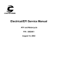
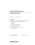
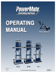
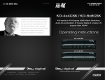
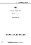
C annondale D iagnostic
Tool M anual
For vehicles (ATV & Motorcycles) equipped with the MC1000 Engine
Management System
Software CD
P/N 971-5001983
Data Cable
P/N 971-5001984
DANGER
POTENTIAL HAZARD
Running the engine indoors.
Breathing exhaust gases.
WHAT CAN HAPPEN
Running the engine indoors will expose you to
dangerous exhaust gases. Breathing carbon
monoxide gas leads to poisoning, asphyxiation, and
death. This will happen rapidly and without notice.
HOW TO AVOID THE HAZARD
Never operate the vehicle indoors even for brief
periods.
Cannondale Diagnostic Tool Manual.fm
© 2001 Cannondale Corporation - All Rights Reserved
P/N 912-5001985
Printed : 11/8/01
S afety A lerts
•
•
FAILURE TO FOLLOW THE WARNINGS CONTAINED IN THIS MANUAL CAN RESULT IN SERIOUS INJURY OR
DEATH.
Keep this Assembly manual in a safe place.
Messages with the Safety Alert Symbol
•
Pay special attention to all messages preceded by the Safety Alert Symbol.
The Safety Alerts symbols means: ATTENTION! BECOME ALERT! YOUR and YOUR CUSTOMER’S SAFETY IS
INVOLVED.
DANGER
Indicates that severe personal injury or
death WILL result if instructions are not
followed.
WARNING
Indicates a potential hazard that COULD
result in serious injury or death.
CAUTION
Indicates a potential hazard that could result in vehicle damage if instructions are not followed.
NOTE :
Provides helpful information
Cannondale Diagnostic Tool Manual.fm
© 2001 Cannondale Corporation - All Rights Reserved
2
Basics
WHAT IS THE CANNONDALE DIAGNOSTIC TOOL?
The Cannondale Diagnostic Tool is a Windows-based software program and special data cable that
enables you to connect and communicate with vehicles using the MC1000 Engine Management System.
The software is installed on a PC or Pocket PC, then the PC (or Pocket PC) is connected to the vehicle
wiring harness via the special data cable. Once the software is installed in the PC and communication
with the vehicle ECU is established, here’s what the tool can do:
•
Send a calibration file from the PC to the vehicle ECU.
•
Receive a calibration file from the vehicle ECU to the PC.
•
Set the vehicle throttle body and injector variables
•
Monitor the (vehicle) ECU operating parameters
•
Read system faults
INSTALLING THE SOFTWARE
To install the Cannondale Diagnostic Tool in your PC, insert the installation CD in your computer CDROM drive. Use the Windows explorer and open the program Setup.exe on the software CD. Follow the
step-by-step instructions. When the installation is complete, go to the security set-up. See next
heading.
SECURITY SET_UP
After the software has been installed on your PC, click on the Windows START button in the lower left
corner of your desktop go to Cannondale DIagnostic and Maintenance Program group and open
SecurityCode.exe. Follow the instructions that are displayed in program window. When the security
code is entered (after you call Optimum Power to get it), you can begin using the software.
ALWAYS MAKE SURE THE VEHICLE BATTERY IS FULLY CHARGED
Before performing any diagnostic work on the vehicle make sure the battery is at full charge. If the
battery voltage is low the ECU power relay may drop out and shut off the ECU. If the battery is not fully
charged the ECU power relay can drop out while the engine is cranking over. Why? During crank over
the battery voltage could drop below the needed latch voltage of 10 volts.
ALWAYS MAKE SURE THE ECU IS POWERED-UP
The vehicle’s ECU operates on a relay controlled power source which is separate from any lighting or
starting electrical systems. The relay “latches-in” the ECU when the crankshaft sensor detects flywheel
movement. If the ECU senses inactivity (no engine start or communications between the PC and ECU)
for two minutes, it powers down. If you try to communicate with the ECU when it is powered-down or off,
the “Failed to Unlock System 125” message will display.
POWERING-UP MOTO ECU’S
On motorcycles, power-up is relatively simple. Press the green start button and release it without
starting the engine. When the system is powered-up the green LED on the data cable “block” will light.
3
P/N 912-5001985
Printed : 11/8/01
POWERING-UP ATV ECU’S
To power-up the ECU on ATVs you have to switch the ignition switch to the “ON” position, then switch
the engine switch to the RUN position. Then, press the green start button and release it without starting
the engine. When the system is powered-up the green LED on the data cable “block” will light.
After 2 minutes of inactivity, the ECU will power-down automatically except with the ATV the data cable
block green LED will not go out. It will remain lit as long as the ATV ignition is in the “ON” position.
CONNECTING THE DATA CABLE
2
1
3
4
1.
2.
3.
4.
Serial connector (female to PC)
Serial connector (male to Pocket PC)
LED
Cable connector (to vehicle)
2
3
3
2
1
1
1.
2.
3.
Motorcycle harness connector - on this model (2002 X440s)
the connector is secured to the relay mounting plate on the
frame spar. Components have been removed for this photo.
Cap
Data interface connector
Cannondale Diagnostic Tool Manual.fm
© 2001 Cannondale Corporation - All Rights Reserved
1.
ATV harness connector - located under the right front fender
near the main fuse
Cap
Main fuse holder
2.
3.
4
“FAILED TO UNLOCK SYSTEM 125”.
This message means that the Cannondale Diagnostic Tool was not able to communicate with the vehicle
ECU. If you see this message check one or more of the following:
•
Make sure that both the vehicle harness connector and data cable are undamaged (pins not bent or
broken) and the connectors are properly locked together.
•
Make sure the vehicle battery is fully charged.
•
Make sure the vehicle ECU is powered-up. See page 3.
•
Make sure the data cable is plugged securely into the PC.
•
Click OK and start again.
5
P/N 912-5001985
Printed : 11/8/01
MAIN SCREEN
(1)
(2)
(3)
(4)
(5)
(6)
(7)
(8)
(9)
00200
(5)
(8)
00200
00200,X440s,082801
(1)
1.
2.
3.
4.
5.
6.
7.
8.
9.
10.
Calibration file identification
Opens a saved calibration file
Receives a calibration file from the vehicle’s ECU
Sends the current calibration file to the vehicle ECU
Used to set the vehicle’s throttle body (min./max. values)
Used to monitor ECU parameters (rpm, throttle body offset, battery voltage, airbox temp, airbox temp, engine temp, IACV)
Receives faults from the vehicle ECU
Used to update throttle body leakage, fuel injector flow rate, injector offset
Progress indicator
Used to display Cannondale Diagnostic Tool version info
Cannondale Diagnostic Tool Manual.fm
© 2001 Cannondale Corporation - All Rights Reserved
6
(10)
1 - CALIBRATION FILE ID
On the top left corner of the Cannondale Diagnostic Tool main screen there will be a Numeric Cal ID
number for the calibration file that is open. If “Untitled” is displayed in this area of the screen, no
calibration file has been opened (from a saved file) or received from the vehicle ECU. In addition to the
ID number, each calibration file is assigned a 128-character description. Although Cannondale assigns a
Numeric Cal ID and description to authorized files, a calibration file is like most other kinds of computer
files. Its possible to changes to the Numeric Cal ID and description through third party software
applications.
Do not experiment with calibration files!
Sending unidentified, altered, or third party calibration files can result in severe damage to the vehicle or
affect the safe operation of the vehicle. You could be severely injured or killed in a resulting accident.
Always consult the Cannondale website (www.cannondale.com) for calibration files authorized for a
specific vehicle identification number (VIN).
The ECU for each ATV and Motorcycle leaving the Cannondale factory is loaded with a specific
calibration file. All calibration files developed by Cannondale are assigned a Numeric Cal ID code. Refer
to "Numeric Cal ID Coding" starting on page 8. The code identifies the model, and sequence of the
calibration file issued. The calibration files SHOULD NOT be interchanged between model VINs or
models. A database of calibrations files is maintained on the Cannondale website so that service
technicians have ready access to the correct factory authorized calibration files for a particular vehicle
VIN. Vehicle’s equipped with a third party (aftermarket) map select interface can toggle maps (and
other fueling features) while the engine is running to meet changing performance demands.
7
P/N 912-5001985
Printed : 11/8/01
NUMERIC CAL ID CODING
MODEL CODE (2 DIGIT)
0
0
YEAR
SEQ (2 DIGIT)
0
00 thru 99
MODEL CODES
Code
Model
0
0
X440s
0
1
X440
0
2
C440
0
3
E440
3
0
Cannibal
3
1
Speed
3
2
Blaze
3
3
Moto 440
YEAR
Year
Code
2002
2
2003
3
2004
4
2005
5
2006
6
2007
7
2008
8
2009
9
2010
0
2011
1
NOTE :
Reset every 10 years
SEQ
00 thru 99
NOTE :
The two digit SEQ number is assigned sequentially. When a
calibration file is updated the SEQ number increases. However,
due to continual product evolution, the updated calibration file for
the model may not be authorized for use in vehicles produced
previously.
Always consult the Cannondale website for the
compatibility of calibration files for a specific vehicle VIN number.
Cannondale Diagnostic Tool Manual.fm
© 2001 Cannondale Corporation - All Rights Reserved
8
2 - OPENING A CALIBRATION FILE
The OPEN Calibration File (saved) button opens the Windows explorer so that you can look for and
open a calibration file that is saved on your PC or Pocket PC. A saved calibration file might be one that
you have received via e-mail, downloaded from the Cannondale website, or one that is stored on a
diskette or CD. This button functions the same way as if you click File - Open.
3 - RECEIVING A CALIBRATION FILE FROM THE VEHICLE ECU
The RECEIVE Calibration File (from ECU) button allow you to receives the calibration file from the
vehicle’s ECU to the Cannondale Diagnostic Tool. It works just like opening a saved calibration file, but
unlike opening a saved calibration file on your computer the calibration file will be “received” from the
vehicle ECU across the data cable.
NOTE :
The received calibration file is not removed from the ECU, it is merely copied into the Cannondale DiagnosticTool
program.
1. Connect the data cable to the computer and vehicle.
2. Open the Cannondale Diagnostic Tool software on your PC.
3. Power-up the vehicle’s ECU.
4. Click the RECEIVE Calibration File (from ECU) button.
After you click the button, the data transfer will start. While the data is copied from the ECU to the PC the
progress indicator in the upper right of the menu will display and the LED on the data cable block may
appear to flicker. The time required for the transfer could vary. It should take place within 1 minute.
When the entire data transfer process is complete, you will see the “Receive complete” message.
5. Click OK. The vehicle calibration file has now been copied to the Cannondale Diagnostic Tool program.
9
P/N 912-5001985
Printed : 11/8/01
4-SEND CALIBRATION FILE (TO ECU)
The SEND Calibration File (to ECU) button “sends” the calibration file open (in the Cannondale
Diagnostic Tool software) to the vehicle ECU.
Whenever you send a calibration file to the vehicle ECU you have to keep the following points in mind:
•
The software will automatically retrieve the vehicle specific variables (throttle positions (min./max),
throttle body offset, injector flow rate, injector offset) from the vehicle’s current calibration file (if
specific values have not been entered manually) and send the retrieved values with the open file. The
process is automatic.
•
Anytime the throttle body is serviced, you will have to reset or “teach” the ECU the new values before
the new calibration file is sent to the ECU. In the case of a replaced throttle body or injector set, you
will have to enter the throttle body offset and injector flow rate, and injector offset variable values that
are supplied with the components in the main screen before sending the calibration file to the vehicle.
Refer to "8 - Updating calibrations" starting on pa ge15.
1. Connect the data cable to the computer and vehicle.
2. Open the Cannondale Diagnostic Tool software on your PC.
3. Power-up the vehicle. When the vehicle is powered-up, the LED on the data cable block with be lit.
4. Open a calibration file or receive a calibration.
5. Click the SEND Calibration File (to ECU) button. The file that is open will be sent to the vehicle ECU. It will
over-write the current calibration file stored in the ECU. When the send has been completed the vehicle
ECU will automatically power itself down. The LED on the data cable block will turn off indicating the ECU
power is now off. The calibration file just sent will remain “open” in the Cannondale Diagnostic Tool software
program until the program is exited or another calibration file is opened or received.
Cannondale Diagnostic Tool Manual.fm
© 2001 Cannondale Corporation - All Rights Reserved
10
5- SET THE THROTTLE POSITION
CAUTION
Set the throttle position with the vehicle off.
This SET Throttle Position button enables you to “teach” the ECU the fully closed and fully open
throttle body plate positions. Teaching the ECU these positions assures that the ECU is calculating fuel
and timing on the information arriving from the Throttle Position Sensor (TPS) mounted on the throttle
body. Slight variations in different vehicles necessitate this teaching step. When a calibration file is
opened or received, the TPS fully closed and fully open voltage values are displayed at the “TPS Sensor
Closed (volts)” and the “TPS Sensor open (volts)” in the main screen.
1. Make sure the throttle plate on the vehicle is completely closed. “Closed” does not mean at the idle position,
rather, it means the idle adjustment screw is backed out until the throttle plate is completely shut. Pay
attention to any tension present in the cable. Tension will hold the plate open. While you can’t see inside the
installed throttle body, checking the position of the throttle set plate position can confirm that the plate is fully
closed.
2. Connect the data cable to the computer and vehicle.
3. Open the Cannondale Diagnostic Tool software on your PC.
4. Power-up the vehicle.
5. Use the OPEN button to open a calibration file that is saved on your PC, or use the RECEIVE button to
open the calibration file that is currently stored in the vehicle ECU. When the calibration file is opened or
received successfully, click the SET Throttle Position button. The following prompt will display:
11
P/N 912-5001985
Printed : 11/8/01
6. Since you already made sure the throttle plate was completely closed click OK to continue. Next, the
following prompt will display:
7. When the prompt above displays, have an assistant fully open the throttle and hold it. While the throttle is
held in the fully open position click OK. Immediately after you click OK, you will see the following prompt:
8. Tell your assistant to release the throttle. Click OK and the Cannondale Dealer Tool will send the open
calibration file (which now includes the new values for fully closed and fully open throttle) to the vehicle
ECU.
When the send is completed, the vehicle ECU will automatically power itself down - the green LED on the
data cable block will go out. Communication from the software to the ECU is now shut down. To recommunicate with the ECU, you will have to power-up the vehicle once again.
9. Power-up the vehicle ECU and click on the MONITOR ECU Parameters button. You are looking for the
“Throttle (%) Open value.”
Now, make sure the ECU parameters display is in the Continuous mode. Adjust the idle adjustment screw
so that the “Throttle (%) Open” value increases by 3%. For example, if the value was 2.3 with the throttle
plate fully closed, you need to adjust this to approximately 5.3 to ballpark the throttle plate position enough
to achieve idle.
Start the engine and allow the vehicle to reach operating temperature (70°C) and fine tune the vehicle idle setting as specified for the vehicle.
NOTE :
Refer to "6 - ECU Monitor" starting on page 13.
Cannondale Diagnostic Tool Manual.fm
© 2001 Cannondale Corporation - All Rights Reserved
12
6 - ECU MONITOR
The MONITOR ECU Parameters button enables you to monitor selected ECU parameters with the
vehicle engine running or with the vehicle engine off. It can be operated in “Continuous” (live) or “Hold”
(snap shot) mode. You can start the vehicle with the monitor running.
1. Connect the data cable to the computer and vehicle.
2. Open the Cannondale Diagnostic Tool software on your PC.
3. Power-up the vehicle ECU.
4. Click the MONITOR ECU Parameters button. The ECU monitor window will be displayed. Click CANCEL
to exit and close the monitor.
This displays the engine RPM.
This displays the % (percentage) that the
throttle plate is open. This value may not
be "0" even with the throttle plate completely
closed.
This is the battery (system) voltage.
This is the air temperature reading
as measured by the airbox air pressure
sensor.
This is the airbox pressure reading
as measured by the ECU sensor.
This is engine temperature reading as
measured by the coolant temperature sensor
This is the position of the
Idle Air Control Valve (IACV). The ECU
moves or "steps" the valve between 0 - 255
depending on the current engine and
air temperature.
Select "Continuous" to view live data.
Select "Hold" to take a snap shot and hold the values displayed.
NOTE :
While this window is open, constant communications between the ECU and PC are occurring - the ECU will not
power itself down. The moment you click CANCEL, the two minute power-down timing will start if no other
communication is attempted.
13
P/N 912-5001985
Printed : 11/8/01
7 - RECEIVE FAULTS (FROM ECU)
The vehicle ECU will record and maintain faults that it encounters during operation. The “RECEIVE
Fault(s) (From ECU)” button enables you to read the codes the ECU is currently encountering. Most
faults reported by the system can be corrected by examining the connector attached to the device or by
tracing the continuity between the ECU connectors and the device connector.
NOTE :
Obtain the vehicle’s wiring diagram before attempting any testing.
1. Connect the data cable to the computer and vehicle.
2. Open the Cannondale Diagnostic Tool software on your PC.
3. Power-up the vehicle. When the vehicle is powered-up, the LED on the data cable block with be lit.
4. Click the “RECEIVE Fault(s) (From ECU)” button. If the ECU is reporting any faults they will be displayed.
POSSIBLE FAULT(s)
Fuel pump fuel short
Fuel pump open short
Sensor power supply fault
Battery voltage low fault
Battery voltage high fault
Coil short fault
Cooling fan short fault (ATV only)
Cooling fan open fault (ATV only)
Injector A short fault
Injector A open fault
Injector B short fault
Injector B open fault
Throttle sensor low fault
Throttle sensor high fault
Stepper motor fault
Crank tooth synch fault
Air temp sensor low fault
Air temp sensor high fault
Engine temp sensor low fault
Engine temp sensor hi fault
NOTE :
The Fault Report window sample above was taken while the Cannondale Diagnostic Tool was connected to an
2002 X440s motorcycle. This vehicle does not have a cooling fan. The “Cooling Fan open fault” will report when
the tool is connected to a motorcycle, however, it can be disregarded. Also for the sample fault report above, we
temporarily disconnected the air temperature sensor - notice the “Air temp sensor high fault” that was reported.
Cannondale Diagnostic Tool Manual.fm
© 2001 Cannondale Corporation - All Rights Reserved
14
8 - UPDATING CALIBRATIONS
The UPDATE Calibrations button enables you to calibrate the Throttle Body Leakage (also called
Throttle Body Offset), the Injector Flow Rate, and Injector Offset. The current values for an open or
received calibration file are displayed in the main screen:
These calibrations compensate or correct for slight manufacturing variations in the vehicle’s throttle body
and/or fuel injectors. Anytime these components are serviced or changed, these values must be
calibrated. The values are loaded to the calibration file when the vehicle is dyno tested and are
determined at the factory. The Cannondale Diagnostic Tool enables you to input these calibrations into
the calibration file manually. If either the throttle body or fuel injectors are replaced - the variables are
supplied by factory analysts and would be packaged with the parts.
1. Connect the data cable to the computer and vehicle.
2. Power-up the ECU.
3. Click the “UPDATE Calibrations” button. The following menu will display.
Type in values and
click "OK."
Click C ncel to exit
without updating.
15
P/N 912-5001985
Printed : 11/8/01
4. Type in the values in the corresponding fields and click “OK.” The new values will display in the main
screen.
5. Now, you have to send these values to the ECU for them to take effect. Click the “SEND Calibration File
(to ECU)” button.
9 - PROGRESS INDICATOR
Whenever data is being transferred between the vehicle ECU and PC a progress indicator displays in
the upper right area of the main screen.
Data transfers should take no more than 1 minute. If the progress indicator freezes for a long time, close
the Cannondale Diagnostic Tool software and try again making sure the cables are connected properly
and that the vehicle battery is fully charged.
RETRYING CHECKSUM
Data is transferred between the vehicle and PC in small “packets” or chunks. During the transfer
process, checks are performed by the diagnostic tool (software) to ensure that the data is not damaged
during the transfer. Each small packet is checked during the transfer. If data errors are detected in the
packet the message “Retrying Checksum...” will display in the progress indicator:
Retrying
Checksum . . .
Typically, this is due to electrical “noise” or other interference during the process. The diagnostic tool will
keep trying automatically.
10 - VERSION INFORMATION
The Cannondale logo in the top right corner of the main menu is a link to the Cannondale Tech Center
website. The site includes all factory issued calibration files. The file can be downloaded via the link.
Follow the link for more details.
Cannondale Diagnostic Tool Manual.fm
© 2001 Cannondale Corporation - All Rights Reserved
16