1
TECHNICAL INFORMATION
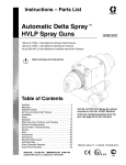
OPERATING INSTRUCTIONS
BITZER AUSTRALIA
BITZER CO2 DX HYBRID PARALLEL COMPRESSOR PLANT
1.General.
2.
Safety Instructions.
3.
Safety Carbon Dioxide ( R744) CO2
4.
Inspection and Unit designation.
5.
Product/Accessories / Check list.
6.Installation.
7.Application.
8.Operation.
9.
Ancillaries/Product Components.
10.
Commissioning data.
11.
Commissioning Sheet.
12.
Service and Maintenance.
13.Drawings.
14.CO2 Pressure Temperature Chart.
15.CO2 Operating Window.
16.CO2 MSDS Sheets.
17.
BITZER OIL BSE 60K MSDS Sheets.
18.
Risk Assessments.
1.General
This document is designed to outline the installation requirements, commissioning & operating instructions for the
successful operation of the BITZER Sub-Critical CO2 DX Hybrid Parallel Compressor Rack.
•
•
•
•
•
•
BITZER Designed and Engineered.
Sub-Critical CO2 Applications only.
DX [Direct Expansion CO2 Evaporators Systems only.] Not suitable for Flooded Evaporator Liquid Recirculation
Cooling.
Hybrid system of mixed origins R744 CO2 Low stage and R134a High stage
Parallel Compressors available in 2, 3 & 4 Compressor line ups, employing the latest BITZER CO2 sub-critical
SL series compressors.
Rack Industry title for multiple refrigeration compressor units.
NOTE: The safety switches, controls, system control valves & electronic controls are not factory set due to
the flexible applications of this unit. All controls must be correctly commissioned by a qualified & trained
technician.
1
BAO-104-1 AUS
2.
Safety Instructions.
All work on compressors and refrigeration systems shall be carried out only by refrigeration personnel who have
been trained and instructed in all work. The qualification and expert knowledge of the refrigeration personnel
corresponds to respectively valid guidelines.
All plumbing work on the [Optional] Hot Water BPHE shall be carried out only by licensed accredited plumbing
personnel who have been trained and instructed in all work. The qualification and expert knowledge of the plumbing
personnel corresponds to respectively valid guidelines. See 9:10
The BITZER CO2 Hybrid Rack is constructed according to the state of the art and valid regulations. Particular
emphasis has been placed on the users’ safety.
Retain these Operating Instructions during the entire lifetime of the BITZER CO2 Hybrid Rack.
2.1 Residual hazards
Certain residual hazards from the BITZER CO2 Hybrid Rack are unavoidable. All persons working on these units
must therefore read these Operating Instructions carefully!
2.2
Safety References
ATTENTION!
Instructions on preventing possible damage to equipment.
CAUTION!
Instructions on preventing minor hazard to persons.
WARNING!
Instructions on preventing a possible severe hazard to persons.
DANGER!
Instructions on preventing an immediate risk of severe hazard to persons.
2.3
General safety references
WARNING!
The BITZER CO2 Hybrid Rack is under pressure with a holding charge of nitrogen to a pressure of 1000 kPa
above atmospheric pressure. Incorrect handling may cause injury to skin and eyes. Wear safety goggles while
working on compressor. Do not open connections before pressure has been released.
CAUTION!
During operation surface temperatures exceed 60°C or fall below 0°C. Serious burns and frostbite are possible.
Switch off and allow cooling down before working on the compressor and associated pipework.
CAUTION!
Compressors contain oil & refrigerant under pressure. Release pressure from both high & low side of compressor
before servicing.
CAUTION!
Tube brazing & compressor operation can produce hot surfaces. To avoid burns, allow surfaces to cool down
before continuing installation or servicing.
2
BAO-104-1 AUS
3
SAFETY CARBON DIOXIDE ( R744)
Carbon dioxide is colourless – odourless gas or cryogenic liquid. The AS1677 Refrigeration standard classifies R744 CO2
as a A1 group refrigerant.
At low concentrations the gas is odourless: @ higher concentrations it has a sharp acidic odour. Carbon dioxide is a
powerful cerebral dilator: It is also an asphyxiate and an irritant. The effects and there concentrations of CO2 refrigerant
are listed below in Table 1.
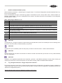
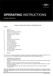
Table 1 Physiological Effects of CO2
PPM
EFFECTS ON HEALTH
350
Normal value in atmosphere
1,000
Recommended not to be exceeded for human comfort
Threshold Limit Value (TLV) - Time Weighted Average (TWA)
Concentration to which one may be repeatedly exposed for 8 hours per day without adverse effects
Can affect the respiration function and case exitation followed by depression of the central nervous system plus
a 50% increase in breathing rate
100% increase in breathing rate after Short Term Exposure Limit (STEL) 15 minutes TWA exposure should not
exceed at any time of day
5,000
20,000
30,000
40,000
50,000
Immediately Dangerous to Life or Health (IDLH) maximum level
100,000 Lowest lethal concentration. Few minutes exposure produces unconsciousness
200,000 Death accidents have been reported
300,000 Quickly results in unconsciousness and convulsions
CAUTION!
Contact with CO2 cold gas or liquid can cause freezing to exposed tissue, Note: Do not attempt to remove clothing which
has stuck to the skin. Burns must be treated by a physician.
CAUTION!
Contact with eyes, immediately wash out with plenty of water for several minutes – Obtain medical attention.
CAUTION!
Moisture with the air can lead to the formation of carbonic acid that can irritate the eyes. All forms of CO2 (carbon dioxide)
are non-combustible.
CAUTION!
Ingestion is not regarded as potential route of exposure, give 200 – 300 millilitres (half pint) of water to drink. Never give
anything by mouth to an unconscious person. Do not induce vomiting. Seek immediate medical attention.
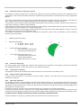
3.1
CO2 Refrigerant detection / Oxygen deprivation detectors:
Ensure that the plant room/s other confined spaces (Coolrooms) are fitted with CO2 detection sensors (systems) or
oxygen deprivation sensor/s. Also refer AS1677 [Accumulation of heavier than air refrigerants.] and [Safety provisions for
personnel in refrigerated spaces.]
Ensure that the plant room has adequate ventilation at all times.
BAO-104-1 AUS
3
3.2CO2 Refrigerant physical properties:
Carbon dioxide CO2 is heavier than air and should not be allowed to accumulate in low lying areas.
Ensure that the current Material Safety Data Sheets for carbon dioxide CO2 are on site.
[See MSD attached]
Melting point
-56.6 °C
Boiling point
-78.5 °C
Density1.977kg /m3
Freezing point
-56.6 °C
Vapour Density
1.53 (air is 1)
Vapour pressure @ 15 °C = 5105 kPa
Soluble in water, ethanol & acetone
Slightly acidic
3.3CO2 Refrigerant Handling and Storage:
• Use only in well ventilated areas
• Storage: Keep in a cool dry, well ventilated place. Do not store above 45°C
3.4CO2 Refrigerant Accidental release measures:
• Personal precautions
• Shut off source of leak if safe to do so
• In poorly ventilated areas or confined spaces, use airline respirator or approved self-contained breathing
apparatus
• Wear approved safety boots and gloves
3.5
Environmental precautions
• Refer to special instructions within safety data sheets
• Clean up actions
• Shut off source of leak, if safe to do so
• Allow product to evaporate
• Ventilate area
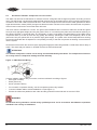
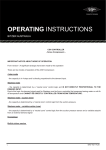
Table 2 shows HAZCHEM ratings for all commonly used refrigerants: The HAZCHEM code provides advisory information
for the emergency service personal to enable them to take appropriate action in the event of an accident. It can be seen
that R744, CO2 has the same HAZCHEM rating as all other commonly used refrigerants. That is to say that in the event
of a major leak of CO2 the emergency services would respond in the same manner as with any of the other commonly
used refrigerants.
Table 2 - HAZCHEM Rating of Refrigerants
Refrigerant
Description
HAZCHEM
Boiling Point
R744
CO2 Carbon Dioxide
2RE
-78.5ºC
ASHREA
Safety Code
A1
R410A
R32 (50%) + R125 (50%)
2RE
-52.2ºC
A1
R404A
R125 (44%) + R123a (52%) + R134a (4%)
2RE
-46.8ºC
A1
R507
R125 (50%) + R143a (50%)
2RE
-46.7ºC
A1
R407C
R32 (23%) + R125 (25%) + R134a (53%)
2RE
-43ºC
A1
R22
Chlorodiflouromethane
2RE
-40.7ºC
A1
R134a
R717
1, 1, 1, 2 - Tertraflouroethane
NH3
2RE
2RE
-26.2ºC
-33.4ºC
A1
B2
Hazard
Asphixiate
Asphixiate in high
concentrations
Asphixiate in high
concentrations
Asphixiate in high
concentrations
Asphixiate in high
concentrations
Asphixiate in high
concentrations
Asphixiate in high
concentrations
TOXIC by inhalation
TLV / TWA
ppm
5000
1000
1000
1000
1000
1000
1000
25
The code can be broken down to:
• The number 2 represents the category of gas, Class 2 being nontoxic.
• The letter R indicates that a water fog or fine mist sprays used by emergency services to contain a spill or major gas
leak.
• The letter E indicates the possibility of evacuation.
4
BAO-104-1 AUS
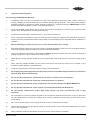
4
Inspection and Designation.
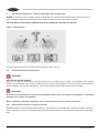
On receiving your BITZER CO2 DX Rack:
1.
Immediately upon receiving the BITZER CO2 DX Hybrid [Parallel Compressor] Rack, please inspect the
crating, packaging and the BITZER Rack for possible damage during shipment. The crating and packaging
has been designed to provide the safest possible protection for equipment transport. IMPORTANT: Contact
BITZER Australia immediately to notify of any damage reported.
2.
Check the BITZER picking slip/list (bill of goods) and product/s provided are correct to your purchase order.
(Check unit/s nameplate/s and record serial number/s).
3.
Accessories are packaged in separate carton/s. See Check list section 5.
4.
Check compressor nameplate to ensure you have the correct model and voltage for the application. Also ensure
that the maximum pressure/temperature ratings listed on the nameplate are not exceeded during installation or
operation.
5.
Before attempting to install rack, be sure to review this document in its entirety.
6.
Ensure that all work carried out on the unit is done by qualified refrigeration personnel, who are suitably trained &
instructed. Applicable safety procedures & practices should be followed.
7.
The unit is supplied under pressure approximately 1000kPa above atmospheric pressure. Failure to relieve the
holding charge in the correct manner may result in injury.
8.
Safety glasses, safety footwear, safety gloves and appropriate work wear must be worn when working on the
unit.
9.
When receiving multiple BITZER CO2 DX racks check and insure that the correct rack is located on the
nominated system platform / designated area.
10.
Install the supplied loose crankcase heaters to each of the compressors.
11.
Do not apply any power supply to the compressor/s unless all suction & discharge shut off service valves are
opened. [Fully back seated position]
12.
Do not operate compressor/s system until in-line valves, controls are set for operation.
13.
Do not operate compressor/s unless the crankcase heater/s are installed
14.
Do not operate compressor/s unless compressors are correctly charged with BITER BSE60K oil.
15.
Do not operate compressor/s unless system is pre-charged with R744 CO2 Refrigerant.
16.
Do not operate compressor/s unless High Stage system has been commissioned and is fully
functional.
17.
Do not operate or provide any electrical power to the compressor unless the terminal box cover is in place and
secured. Measurement of amps and voltage during running conditions must be taken at other points in the
power supply.
18.
Do not remove terminal box cover until all electrical sources have been disconnected.
19.
Follow recommended safety precautions listed on the terminal box cover label before attempting any service
work on the compressor.
20.
During operation surface temperatures can exceed +60°C. Severe burns are possible.
BAO-104-1 AUS
5
5
Product/Accessories/Check List.
Component Check list for 2 Compressor CO2 DX Rack
•
•
•
•
•
•
•
•
•
•
•
•
1 x BITZER CO2 DX Twin Compressor Parallel Rack.
2 x BITZER Compressor instructions c/w spare service valve gaskets for compressors.
1 x Wooden packing crate.
2 x Crankcase heaters [Supplied loose]
6 x One Litre cans of BSE60K BITZER Compressor Refrigeration Oil. [Item No. I06-033]
6 x Embelton NR3 Equipment Mounting feet each 500kg Rated. [Item No. P37-053]
2 x Traxon Oil level Control electrical leads.
1 x Suction Drier felt Element F48
2 x Liquid line Drier Cores 48-DM. 100% Molecular sieve [Item No. S03-033]
1 x Henry Optical level Switch E-9224A N.C. 24V AC/DC [Item No. K06-003] to suit Liquid Receiver bottom
Sight Glass.
2 x Henry Frost Shield [Perspex viewing elements] to suit Liquid Receiver Top and middle Sight Glasses.
1 x spare Temprite coalescent Oil Cartridge sized to application [when Temprite Oil Separator selected]
Component Check list for 3 Compressor CO2 DX Rack
•
•
•
•
•
•
•
•
•
•
•
•
1 x BITZER CO2 DX Three Compressor Parallel Rack.
3 x BITZER Compressor instructions c/w spare service valve gaskets for compressors.
1 x Wooden packing crate.
3 x Crankcase heaters [Supplied loose]
9 x One Litre cans of BSE60K BITZER Compressor Refrigeration Oil. [Item No. I06-033]
6 x Embelton NR3 Equipment Mounting feet each 500kg Rated. [Item No. P37-053]
3 x Traxon Oil level Control electrical leads.
1 x Suction Drier felt Element F48
2 x Liquid line Drier Cores 48-DM. 100% Molecular sieve [Item No. S03-033]
1 x Henry Optical level Switch E-9224A N.C. 24V AC/DC [Item No. K06-003] to suit Liquid Receiver bottom
Sight Glass.
2 x Henry Frost Shield [Perspex viewing elements] to suit Liquid Receiver Top and middle Sight Glasses.
1 x spare Temprite coalescent Oil Cartridge sized to application [when Temprite Oil Separator selected]
Component Check list for 4 Compressor CO2 DX Rack
•
•
•
•
•
•
•
•
•
•
•
•
1 x BITZER CO2 DX Four Compressor Parallel Rack.
4 x BITZER Compressor instructions c/w spare service valve gaskets for compressors.
1 x Wooden packing crate.
4 x Crankcase heaters [Supplied loose]
12 x One Litre cans of BSE60K BITZER Compressor Refrigeration Oil. [Item No. I06-033]
6 x Embelton NR3 Equipment Mounting feet each 500kg Rated. [Item No.P37-053]
4 x Traxon Oil level Control electrical leads.
1 x Suction Drier felt Element F48
2 x Liquid line Drier Cores 48-DM. 100% Molecular sieve [Item No.S03-033]
1 x Henry Optical level Switch E-9224A N.C. 24V AC/DC [Item No. K06-003] to suit Liquid Receiver bottom
Sight Glass.
2 x Henry Frost Shield [Perspex viewing elements.] to suit Liquid Receiver Top and middle Sight Glasses.
1 x spare Temprite coalescent Oil Cartridge sized to application [when Temprite Oil Separator selected]
6
BAO-104-1 AUS
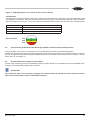
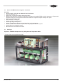
6Installation.
BITZER Sub-Critical CO2 DX Hybrid racks are designed exclusively for indoor use, preferably within a designated
plant equipment room. Refer enclosed safety data, especially 3.1 and Risk assessment documentation prior to any
equipment unloading from transport, lifting, and installation.
WARNING! Careful considerations to lifting should be applied, prior to removal from transporter.
Instructions:
1.
The BITZER CO2 Rack should only be lifted from the base.
2.
The BITZER CO2 Rack should remain within its wooden crate until, located on designated area within plant
room.
3.
The BITZER CO2 Rack must remain perpendicular [upright] and level during installation.
4.
A single BITZER CO2 Rack unit will have a Net Weight between 1250kg up to 2100kg depending on Number
of Compressors, Compressors models, BPHE’s and options applied.
5.
The BITZER CO2 Rack must be set on a flat level foundation.
6.
The designated plant room floor area, must allow for the rack weight and size, Including the Refrigerant weight,
Electrical wiring / Equipment, and conform to current building codes.
7.
Clearances: A safe working space surrounding 360˚ to be provided, including free access to above and must
conform to current building codes. A safe working distance must also apply to any adjacent switchboards or
mains boards.
8.
Free working space is required for service of the BITZER DX CO2 Hybrid Rack.
9.
When the BITZER DX CO2 Hybrid Rack is located in its designated location. Unpack the wooden crate/ Plastic
wrapping; Install the Embelton mounting feet to both the floor and the unit frame. Adjust mounting feet until the
rack is level.
Embelton NR3 adjustable mounting foot. Capacity 500Kg each. [Item No. P37-053]
10.
11.
12.
13.
14.
15.
The Embelton mounting feet slightly raise the BITZER DX CO2 Hybrid Rack off the floor allowing free space
for a metal condensate / oil tray to be inserted at floor level. [Recommended]
Ensure that fully operational [tested/certified] CO2 Refrigerant detection / Oxygen deprivation
detectors: Are installed prior to receiving any R744 CO2 refrigerant to site.
The equipment plant room should be free of dust before the BITZER DX CO2 Hybrid Rack is connected to any
field piping to ensure internal cleanliness.
Ensure that the system nitrogen holding charge is expelled from the BITZER DX CO2 Hybrid Rack, prior to any
attempts at connecting field piping.
Ensure that the BITZER DX CO2 Hybrid Rack and all refrigeration field piping are not exposed to atmosphere
for any long periods.
The System (field) piping must be to AS1677. An inert gas [Dry Nitrogen] must be charged through field
refrigeration pipe work during the brazing process. It is recommended that the inert gas be delivered into the
pipework, so that air is not also introduced.
BAO-104-1 AUS
7
7Application.
BITZER Sub-Critical CO2 DX Hybrid Racks are designed exclusively for the use of Carbon Dioxide (R744) as the low
stage refrigerant and R134a as the high stage refrigerant, in a two stage, Cascade system, where the R744 CO2 systems,
evaporators are of direct expansion design.
They are designed to be applied in Low Temperature refrigeration applications & ideal for medium to large supermarkets,
Industrial processes, and Frozen Food Storage Rooms.
ATTENTION!
BITZER CO2 Hybrid Racks are exclusively intended for the use in low temperature sub-critical cascade
applications. This documentation applies to BITZER DX CO2 Parallel Hybrid Racks Series only.
The BITZER CO2 Hybrid series are a factory assembled range of highly efficient and reliable multiple compressor
refrigeration racks, designed with all piping, ready for onsite connection, including all required components (excludes
R134a EEV’s), controls, transducers and safety devices.
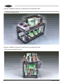
The BITZER CO2 Hybrid rack is designed with simplicity and serviceability in mind. Figure.1 shows a system schematic
outlining the design and refrigerant flow. Details of specific component operation are outlined in section 6.
The BITZER CO2 Hybrid racks are individually fabricated to each particular, specific application.
The BITZER CO2 Hybrid racks comprise of:
•
1 x BITZER Designed / Engineered Structural Steel Unit frame Assembly.
•
1 x BITZER Compressor Mount cradle.
•
2-4 BITZER SL Series CO2 Compressors.
•
2-4 Stainless Steel Suction Lines [from 1-Core Suction Drier / Accumulator Vessel to each Compressor]
•
1 x BITZER 1-Core Drier Shell / Accumulator Metal Clad and Insulated Vessel.
•
2-4 Steel Discharge Branches,
•
1 x Steel Discharge manifold and steel discharge pipe to oil separator.
•
1 x Oil Separator/Reservoir sized to application. [Optional: BITZER COS or Temprite Coalescent Oil Separator
/ Reservoir]
•
Two in parallel BPHE Cascade Condensers c/w Metal Cladding and 75mm Insulation. Engineered to application
and clients Specifications. [BPHE’s CO2 Condenser side and R134a Evaporator side]
•
1 x Suction Re-Heat BPHE c/w Metal Cladding and Insulation. Engineered to application.
•
1 x Emergency Cooling BPHE Cascade Condenser/Evaporator R744 / R134a comes with R134a Tx Valve. To maintain
refrigerant CO2 temperature/pressure within the Liquid Receiver during IE: catastrophic system failure / power
failure.
•
1 x Horizontal liquid Receiver c/w Level Indicator Sight glasses, engineered to application.
•
1 x BITZER Dual Suction/Liquid header Assembly c/w Insulated PVC Enclosure, Suction ball Valves/service
valves, Liquid ball valves.
•
1 x Liquid line 2-Core Drier Assembly c/w c/w Insulated PVC Enclosure, Liquid Line By-Pass circuit for continuous
run during drier replacement and one Ø3/8” MSAE post service valve for system charging or refrigerant reclaim
prior to Drier core replacement.
•
Compressor pressure controls 1 x LP and 1 x HP per compressor.
•
System Pressure Controls (5.) comprising of 1 x LP and 4 x HP controls.
•
BITZER Pressure Relief Manifold consisting of 1 x LP Pressure Relief Valve 2500kPa, 6 x HP Pressure Relief
Valves 4000kPa, 1 x LP Bleed Solenoid, 1 x HP Bleed Solenoid, associated Service valves, 1 x LP transducer
port c/w service valve and 1 x HP transducer port c/w service valve.
•
System interconnecting refrigeration pipe work engineered to application and safe working pressure specifications.
•
System interconnecting flexible hoses engineered to application and safe working pressure specifications.
•
All Refrigeration Ball Valves, Packed Capped Valves, Rotolock Valves, Check Valves, inline products, Copper
Tubing, Copper Fittings, Brass Fittings, Flexible Lines are safe working pressure rated at greater than 2500kPA
low side and greater than 4500kPA High side.
8
BAO-104-1 AUS
8Operation.
The BITZER DX CO2 Hybrid racks
•
The High pressure liquid CO2 leaves the Liquid Receiver via the insulated liquid line. This liquid enters a
CO2 liquid/CO2 suction vapour Brazed Plate Heat Exchanger (BPHE). The purpose of this heat exchanger
is to add additional superheat to the suction return vapour. This ensures that the oil in the compressor
crankcase is sufficiently warm to avoid catastrophic compressor failure. An additional hot gas injection is
installed into the suction line to ensure sufficient superheat. This design also provides simultaneous sub
cooling to the liquid supply to the evaporators.
•
There is a liquid line by-pass circuit complete with inline (NC) solenoid valve, prior to the (BPHE) this solenoid
when open causes the liquid refrigerant to partially by-pass the (BPHE) reducing the amount of superheat
of the return suction CO2.The Liquid CO2 leaves the BPHE via a three way ball valve then on to the 2-core
[100% molecular sieve] drier shell. There is also a drier shell by-pass circuit to simplify drier core changeover,
while the system remains in operation. The by-pass is operated by the liquid line three way ball valve and
straight thru ball valve. We have also provided a Ø3/8” post valve for liquid charging, fast evacuation or
reclaiming refrigerant from the drier cavity prior to drier core replacement. The liquid refrigerant exiting the
liquid line then enters the four, six or eight circuit liquid header [manifold]. The sub cooled liquid then enters
field piping to the LT evaporators via electronic expansion valves [located at fixtures] and returns to the rack
as superheated vapour via the four, six or eight circuit suction (return) header (manifold).
•
The suction vapour then flows within the suction line to the CO2 suction vapour (BPHE) gaining superheat.
The suction return vapour then enters the suction filter/ accumulator vessel, before reaching the compressors.
•
The low pressure suction vapour then enters the compressor/s where it becomes compressed to a high
superheated pressure then discharged into a common header before it enters the Oil Separator/Reservoir.
The Oil is separated/filtered and returned back to the compressor/s via an oil manifold.
•
Individual oil levels within each compressor are maintained with TRAX oil controls fitted to the crankcase of
each compressor.
•
The high pressure discharge vapour once leaving the oil separator can be directed to the (Optional) dual
wall Hot Water BPHE or directly to the integral or remote Air Cooled De-Superheater. The BITZER Air cooled
De-Superheater reduces the discharge gas temperature to an acceptable level where the vapour can be
permitted to enter the matched parallel set of BPHE Cascade Condensers/Evaporators.
•
The matched set [two in parallel] CO2/R134a BPHE Condensers / Evaporators, remove the CO2 THR (total
heat of rejection) and condense the CO2 back into liquid state. Condensing is achieved by the counter flow of
R134a liquid refrigerant evaporating from the high stage of the Cascade system. The liquid CO2 then drains
into the insulated horizontal Liquid Receiver where the whole process continues.
NOTES:
•
The Air Cooled De-Superheater is mandatory requirement on all BITZER DX CO2 systems. The Air Cooled
De-Superheater provides improved efficiency, reliability and ensures that the BPHE’s Cascade Condensers/
Evaporators are within their small operating envelope.
•
Operating a BITZER DX CO2 rack without an Air Cooled De-Superheater voids all warranty.
•
The Air Cooled De-Superheater should be set to maintain a CO2 outlet temperature of less than 60kTD above
the R134a Evaporation temperature.
BAO-104-1 AUS
9
Figure 1 - BITZER CO2 Hybrid Rack Schematic .
LEGEND
SIX SUCTION LINE INLETS [Top Entry.]
Ø7/8"
BITZER CO₂ Compressor With Trax Oil
Ø7/8"
Ø7/8"
Ø7/8"
Ø7/8"
SIX LIQUID LINE OUTLETS [Bottom Exit.]
Ø7/8"
Ø7/8"
Ø7/8"
Ø7/8"
Ø7/8"
Ø7/8"
Ø7/8"
BITZER
DUAL SUCTION / LIQUID
HEADER ASSY. PVC
Clad & Insulated
ؼ” FF
Flexible
Line. [TYP.]
BPHE Brazed Plate Heat Exchanger CO2 various Applications.
BITZER Single Core Suction
Drier / Suction Accumulator
REMOTE AIR COOLED
DE-SUPERHEATER [GAS COOLER.]
CO2 SENSIBLE HEAT REMOVAL
[MANDITORY.]
Solenoid Valve (NO)
¼”
¼”
¼”
¼”
¼”
¼”
Solenoid Valve (NC)
Ø1-3/8"
Metering Device [ TX Valve ]
Shut Off Valve (NO)
Ø1-1/8"
Ø1-3/8"
Ø1-3/8"
Shut Off Valve (NC)
Field Piping by contractor.
Ø1-1/8"
Compressor Pressure Relief Valve 25bar
Ø1-1/8"
BPHE Emergency CO2 Cooling:
Condenser R744
/ Evaporator R134a
Metal Clad & Insulated
Capped Ø1-1/8 Tube
Connections To and From
Remote [De-Superheater]
Gas Cooler.
SL Series Compressor Pressure Relief Valve 30bar
Ø1/4"
Field Piping by contractor.
Ø1-1/8"
Ø1/4 Access Valve
Water Inlet [Hot Water Circuit. ]
External Threaded Connections
1-¼” MBSP 265 NM MAX. TORQUE
Ø3/8 Access Valve
v
Two Core Liquid Drier
Low Pressure Switch
P
High Pressure Switch
I-2
Ø1-1/8"
LP
LP
Transducer Connection
LP BLEED
2450 KpA
SET POINT
Ø3/8 Oil Strainer
I-2
HP
B
L
E
E
D
R
A
C
K
p
E
M
E
R
G
E
C
Y
p
HP
R
A
C
K
p
I-2
Ø3/8"
3 Way
Ball
Valve
Rotolock Shut Off Valve
Shut Off Valve [ 3-Way Ball Valve ]
Ø3/8"
Ø3/8"
Ø3/8" Hot Gas Injection Circuit.
Ø1-3/8"
Oil Separator
Ø3/8"
TEMPRITE Pressure
Differential Indicator
Ø1-3/8"
SINGLE CORE
FILTER [END.]
SUCTION Ø1-3/8" 1-CORE
p
TEMPRITE
Pressure
Differential
Indicator
B36-088
Colorbond Metal Clad
& Insulated.
Ø3/8"
SERVICE VALVE
FILTER
MAINTENANCE
p
Steel
Discharge
Branch
SUCTION BRANCH
CDS STAINLESS
STEEL
ؼ” FF
Flexible
Line
Comp No.1
p
p
SUCTION BRANCH
CDS STAINLESS
STEEL
ؼ” FF
Flexible
Line
Steel
Discharge
Branch
p
Oil Return Manifold
Ø1-5/8"
R744
Liquid
Outlet
A
BPHE
R744
PVC Clad
& Insulated.
Ø1-1/8"
TWO CORE
FILTERS [END.]
Ø7/8"
Ø1-1/8"
Liquid Line.
Ø3/8"
Ø3/8" SERVICE
VALVE.
BLEED FOR FILTER
MAINTENANCE.
& CO2 CHARGING
Inlet
Outlet
Liquid
Inlet
B30-254
CO₂ RECEIVER
PUMP DOWN CAPACITY
@80% 110Kg @ -4˚C
Inlet
ؼ” FF
Flexible
Line
Liquid
Outlet
Liquid
Inlet
Roto Lock
Valve
Liquid Line.
Notes:
▪ BITZER - Schematic Rack System R744 2013
▪ Intellectual Property of BITZER.
▪ Electronic Tx Valves to each R744 / R134a BPHE By others.
▪ Valves / Solenoids Coloured Red are Normally Closed
▪ Liquid Line Drier By- Pass [3-Way Ball Valves] Standard.
▪ We reserve to right to change design – specifications
without notice.
▪ Optional Emergency Cooling Condensing Unit Not Shown.
B36-073
TEMPRITE
925R COALESCENT
AS 2971 APPROVED.
Oil Separator / Reservoir.
Liquid level Sight Glass Inc.
Low Level [Alarm.] Probe.
Liquid level Sight Glasses
Front Facing.
▪ Remote Air Cooled De-Superheater Not Shown.
▪ Not to scale.
Colorbond Metal Clad
& Insulated.
BITZER Australia Pty Limited
Comp No.3
Compressor Sequence viewed from front.
Ø1-1/8"
R134a
Liquid
Inlet
Ø7/8"
Pressure Relief
Socket
SUCTION BRANCH
CDS STAINLESS
STEEL
ؼ” FF
Flexible
Line
Steel
Discharge
Branch
Comp No.2
Steel Discharge Main Manifold
p
Ø7/8"
Ø1-5/8"
R744
Liquid
Outlet
A
Outlet
ؼ” FF
Flexible
Line
DRIER / SUCTION ACCUMULATOR 3 COMP.
Ø1-1/8"
R134a
Liquid
Inlet
ؼ” FF
Flexible
Line
Steel Discharge Line Ø1-1/8"
TEMPRITE
Ø1-1/8"
BPHE
R134a / R744
Ø1/4"
Liquid Inlet [Liquid Receiver]
Ø1/4"
Ø1-1/8"
BPHE
R134a / R744
HP BLEED
3950 KpA
SET POINT
Sight Glass with Optical Level Sensor [Fitted]
Water Inlet [Hot Water Circuit. ] 1-¼” MBSP
Ø1-5/8"
A
R134a
Tx Valve
c/w
Orifice
Sight Glass [ Liquid Receiver]
Water Outlet [Hot Water Circuit. ] 1-¼” MBSP
Ø1-5/8"
Ø3/8"
B
L
E
E
D
p
R744
Vapor
Inlet
Ø2-1/8"
R134a
Vapor
Outlet
A
A
HP
p
R744
Vapor
Inlet
Ø2-1/8"
R134a
Vapor
Outlet
BPHE
R134a / R744
Copper Discharge Line Ø1-1/8"
P
BPHE
Suction Re-Heat
Metal Clad & Insulated
A
Water Outlet [Hot Water Circuit. ]
Sight Glass [Oil.]
BPHE Cascade
Condenser R744
/ Evaporator R134a
Metal Clad & Insulated
Liquid Line Drier Bypass
BPHE [Dual Wall.]
R744 / H2O
HOT WATER
[HEAT RECLAIM.]
Non Return Valve [Check Valve]
BPHE Cascade
Condenser R744
/ Evaporator R134a
Metal Clad & Insulated
R134a
Vapor
Outlet
Ø1-1/8"
Liquid Line.
Ø1-1/8"
System Pressure Relief Valve 40bar
Suction Super Heat BPHE
System Pressure Relief Valve 25bar
Ø3/8"
ABN 70 057 670 023
134-136 Dunheved Circuit
St Marys NSW 2760
Private Bag 7, St Marys 1790
Tel.: +61 (2) 8801 9300
Fax: +61 (2) 9673 4698
BITZER AUSTRALIA 2013
NOTES:
•
Schematic depicting 3- Compressor DX CO2 Rack
•
Schematic depicting system complete with Temprite Oil Separator/Reservoir and Pressure Differential
Indicator
•
Schematic depicting system complete with Hot Water BPHE
•
Remote Air Cooled De-Superheater depicted with dotted lines. (Integral Air Cooled De-Superheater Option not
shown)
•
Remote or integral Air Cooled Condensing Unit for Emergency Cooling BPHE option not shown
10
BAO-104-1 AUS
Figure 1A - Thermocouple probe Locations BITZER CO2 Hybrid Rack Schematic .
SIX SUCTION LINE INLETS [Top Entry.]
Ø7/8"
Ø7/8"
Ø7/8"
Ø7/8"
Ø7/8"
SIX LIQUID LINE OUTLETS [Bottom Exit.]
Ø7/8"
Ø7/8"
Ø7/8"
Ø7/8"
Ø7/8"
Ø7/8"
Ø7/8"
ؼ” FF
Flexible
Line. [TYP.]
De-Superheater Outlet.
Discharge Temperature
Sensor.
High Temperature Probe.
¼”
¼”
¼”
¼”
¼”
¼”
Ø1-3/8"
Ø1-1/8"
Ø1-3/8"
Ø1-3/8"
Field Piping by contractor.
Ø1-1/8"
Ø1-1/8"
Capped Ø1-1/8 Tube
Connections To and From
Remote [De-Superheater]
Gas Cooler.
R134a Suction
Temperature Sensor.
[From High Stage System.]
B
L
E
E
D
I-2
p
HP
HP
R
A
C
K
E
M
E
R
G
E
C
Y
p
p
p
BPHE
R134a / R744
Thermocouple
B
L
E
E
D
I-2
p
Ø1-1/8"
BPHE
R134a / R744
HP BLEED
3950 KpA
SET POINT
Ø3/8"
3 Way
Ball
Valve
Ø3/8"
Ø1-3/8"
BPHE
R744
Ø1-1/8"
Ø3/8"
Ø3/8" SERVICE
VALVE.
BLEED FOR FILTER
MAINTENANCE.
& CO2 CHARGING
ؼ” FF
Flexible
Line
Inlet
Outlet
Outlet
Ø3/8"
SERVICE VALVE
FILTER
MAINTENANCE
Pressure Relief
Socket
ؼ” FF
Flexible
Line
p
Thermocouple
p
ؼ” FF
Flexible
Line
Flexible
Line
Comp No.2
Steel Discharge Main Manifold
Comp No.3
Oil Return Manifold
Compressor Sequence viewed from front.
B30-254
CO₂ RECEIVER
PUMP DOWN CAPACITY
@80% 110Kg @ -4˚C
Liquid
Inlet
Liquid
Outlet
Liquid
Inlet
Roto Lock
Valve
Liquid Line.
Notes:
▪ BITZER - Schematic Rack System R744 2013
▪ Intellectual Property of BITZER.
▪ Electronic Tx Valves to each R744 / R134a BPHE By others.
▪ Valves / Solenoids Coloured Red are Normally Closed
▪ Liquid Line Drier By- Pass [3-Way Ball Valves] Standard.
▪ We reserve to right to change design – specifications
without notice.
▪ Optional Emergency Cooling Condensing Unit Not Shown.
p
Thermocouple
ؼ” FF
ؼ” FF
Flexible
Line
Comp No.1
p
▪ Remote Air Cooled De-Superheater Not Shown.
Steel Discharge Line Ø1-1/8"
SUCTION BRANCH
CDS STAINLESS
STEEL
Thermocouple
Thermocouple
Inlet
ؼ” FF
Flexible
Line
DRIER / SUCTION ACCUMULATOR 3 COMP.
Ø1-1/8"
TWO CORE
FILTERS [END.]
Ø7/8"
Liquid Line.
Ø3/8"
p
BPHE
R134a / R744
Ø1/4"
Ø3/8"
Ø1/4"
Ø1-1/8"
R134a
Tx Valve
c/w
Orifice
HP
Ø3/8" Hot Gas Injection Circuit.
p
Thermocouple
Copper Discharge Line Ø1-1/8"
LP
R
A
C
K
LP BLEED
2450 KpA
SET POINT
Liquid Line.
v
LP
Crankcase Temperature
Sensor.
Attached to Each Compressor Sump.
Thermocouple
Liquid Line Drier Bypass
Suction Temperature
Sensor.
400mm to 300mm Upstream
of Hot Gas Injection line
SUCTION Ø1-3/8" 1-CORE
Ø1-1/8"
Thermocouple
Ø1-1/8"
Ø1-3/8"
SINGLE CORE
FILTER [END.]
R134a Suction
Temperature Sensor.
[From High Stage System.]
Ø1/4"
Field Piping by contractor.
Thermocouple
Liquid Line Temperature
Sensor
▪ Not to scale.
Discharge Temperature
Sensor.
High Temperature Probe.
BITZER Australia Pty Limited
Ø3/8"
ABN 70 057 670 023
134-136 Dunheved Circuit
St Marys NSW 2760
Private Bag 7, St Marys 1790
Tel.: +61 (2) 8801 9300
Fax: +61 (2) 9673 4698
BITZER AUSTRALIA 2013
NOTES:
•
Schematic depicting 3- Compressor DX CO2 Rack with recommended Thermocouple Probe locations
•
Additional Probe locations
•
The CO2 Suction Line outlet of Suction Re-Heat BPHE
•
The Discharge line before the cascade condenser BPHE’s
•
Both Liquid CO2 Outlets of cascade condenser BPHE’s before Liquid Receiver
BAO-104-1 AUS
11
9. Ancillaries /Compressors
At the heart of the BITZER CO2 Hybrid Rack is the BITZER Octagon CO2 compressor, the solid drive gear design and
valve plate construction have been specifically adapted to the requirements of CO2 which leads to a further increase
in operational efficiency.
BITZER SL Series sub-critical CO2 Compressor.
Maximum Permissible Pressure (standstill)
Suction side:
SL Models 30 Bar.
Discharge side:
SL Models 53 Bar.
HC Models: 25 Bar.
HC Models: 43 Bar.
Minimum Suction Gas Superheat:
20K, lower suction gas superheat is possible provided that the minimum oil and discharge gas temperatures are
maintained.
Minimum Oil Temperature:
20°C (for continuous operation oil temp should not fall below 30°C).
Minimum Discharge Temperature:
40°C (for continuous operation discharge temp should not fall below 50°C).
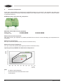
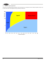
Operating Envelope BITZER CO2 Sub Critical Compressors.
Note:
•
•
•
12
SL Series Latest Generation.
HC Series Previous Generation still current.
1st Generation.
BAO-104-1 AUS
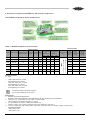
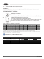
9. Ancillaries /Compressors BITZER CO2 Sub-Critical Compressors
The BITZER CO2 Hybrid SL Series Compressors
Table 3 - BITZER Compressor Technical data.
Electrical Data
Technical Data
Pipe Connection
DL
Suction Line
mm
Inch.
mm
Inch.
J04-469
2MSL-07K
1.73
2
1.0
47
12
½"
16
⅝"
J04-490
2KSL-1K
2.71
2
1.0
47
12
½"
16
⅝"
J04-491
2HSL-3K
4.34
2
1.0
50
12
½"
16
⅝"
J04-492
2FLS-4K
6.36
2
1.0
53
12
½"
16
⅝"
J04-493
2DSL-5K
9.23
2
1.5
77.5
16
⅝"
22
⅞"
J04-494
2CSL-6K
11.20
2
1.5
94
16
⅝"
22
⅞"
J04-495
4DSL-10K
18.45
4
2.0
94.5
22
⅞"
28
1-⅛"
Motor Connection
Volt
265..290V ∆-3 - 60Hz, 440..480V ϒ-3 - 50Hz
Pipe Connection
DL
Discharge Line
∆/ϒ
Displacement with Number of Oil Charge Weight
dm3
1450 min-1 m3/Hour Cylinders
Kg
220..240V ∆-3 - 50Hz, 380..420V ϒ-3 - 50Hz
Item No. Compressor Type
Max.
Max.
Starting
Operating
Power
Current
Current. Consumption (Locked Rotor.)
Amp.
kW
Amp.
4.5/2.5
1.1
25.6/14.8
6.1/3.5
1.8
39.0/22.5
10.7/6.0
3
44.2/25.5
15.4/8.6
4.6
68.1/39.3
20.1/11.3
6.4
107.7/62.2
24.8/13.9
7.8
107.7/62.2
39.3/22.0
12.7
168/97
Crankcase Heater
230V
•
2MSL-07K..2FSL-4K: 0..60W
Self regulating PTC Heater
2ESL-4K..4CSL-12K: 0..120W
Self regulating PTC Heater
4VSL-15K..4NSL-30K: 0..140W
Self regulating PTC Heater
•
•
i
Crankcase heater is generally required
due to high solubility of CO2 in the oil
Explanations
① BSE60K: Oil Standard applications
BSE85K: Oil Booster applications and applications with high discharge gas temperatures
② Tolerance (+or- 10%) based on mean value of voltage range.
Other voltages and electrical supplies on request.
③ For the selection of contacts, cables and fuse the max.
Working current / max. power consumption must be considered. See also ④
④ Data for compressors with voltage 380V.. 420V (220.. 240V) are based on average voltage of 400V (230V)
Conversion factors:
380V (220V) 0.95
420V (240V) 1.05
BAO-104-1 AUS
13
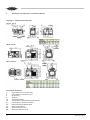
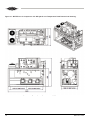
9.
Ancillaries /Compressors: Crankcase Heaters.
Figure 2.0 - Dimensional Drawings:
Connection Positions:
1. High Pressure Connection (HP)
2. Low Pressure Connection (LP)
5.
Oil Fill Plug
6.
Oil Drain
10.
Crankcase Heater
16. Connection for Oil Monitoring (Oil Sensor)
21. Connection for Oil Service Valve
22.
External Pressure Relief Valve
24.
Service Connection
SL.
Suction Service Valve
DL.
Discharge Service Valve
14
BAO-104-1 AUS
Figure 2.1 - Dimensional Drawings:
Connection Positions:
1. High Pressure Connection (HP)
2. Low Pressure Connection (LP)
5.
Oil Fill Plug
6.
Oil Drain
10.
Crankcase Heater
16. Connection for Oil Monitoring (Oil Sensor)
21. Connection for Oil Service Valve
22.
External Pressure Relief Valve
24.
Service Connection
SL.
Suction Service Valve
DL.
Discharge Service Valve
BAO-104-1 AUS
15
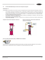
9. Ancillaries /Compressors: Suction Filter [within each Compressor]
BITZER compressors of the “Octagon” series are designed with a Suction Filter located under the Suction service
valve. This filter is easily removed for inspection / cleaning when necessary IE: During oil change.
SUCTION GAS FILTER SHOULD ALWAYS BE IN SL (A) POSITION ON BITZER CO2 RACKS
Figure 3 - Suction Filter
For futher information refer to document KB100-5 @ www.bitzer.com.au
9.2
Ancillaries/ Electrical Connections
WARNING!
ELECTRICAL SHOCK HAZARD
Failure to comply with these safety warnings could result in serious injury or death. All installation and servicing
activities should be performed only by trained personnel. Wear safety goggles. Shut off all power to this equipment
during installation, service and maintenance. Lock and tag all disconnect locations until work is complete.
WARNING!
All electrical wiring should be carried out by qualified persons and in accordance with AS3000 or equivalent
standard in the country of installation.
Refer to AS3000 for electrical installation and for service/ maintenance of electrical equipment
9.2.1
Electrical Connections; Frequency Inverters
BITZER Australia recommends that that the lead CO2 compressor should operate with a frequency inverter in order to
reduce compressor cycling. It is also advantages as higher system efficiency can be achieved, especially under partial
load.
16
BAO-104-1 AUS
9.2.2
Selection Criteria; Frequency Inverters
The frequency inverter must be able to continuously supply the maximum operating current to the compressor motor
additionally, a 10% reserve should be planned for. Selections should be made in accordance with KT-420-1 Application
Manual.
The torque of reciprocating compressors is not constant with the angle of rotation, the higher the number of cylinders, the
more constant the torque, thus a greater starting torque is required for a smaller number of cylinders.
The maximum current must be within the transient overload rating of the frequency inverter. If this is not the case, then a
larger type of frequency inverter must be selected.
Several values of rated current (constant and quadratic torque ratings) are provided by frequency inverter manufacturers,
select a frequency invertor based on a constant torque rating.
The frequency inverter must be capable of briefly delivering over torque during the starting phase in order to overcome
the break-away torque and too accelerate the drive.
This results in increased current demand for starting the compressor, which must be provided for by the frequency
inverter in the ramp up time.
Variable speed drive (VSD)
Standard speed range:
HC Series: 30 Hz .. 50 Hz
SL Series: 30 Hz .. 60 Hz
Trans-synchronous operation:
motor reserve limited with R744
(constant torque requirement)
For a constant torque above 50 Hz
VSD with auxiliary transformer
(higher output voltage)
Motor layout 230 V / 3 / 50 Hz
9.2.3 Electronic Screening
Use screen cables. Ensure large area contact to the housing of the compressor. The frequency inverter must be fitted
with suitable EMC filters, connect both ends of motor cable to the ground.
9.2.4 Compressor Contactor
A compressor contactor should always be used to ensure the correct function of the safety circuit.
9.2.5 Ramp up time to Minimum Speed
A Ramp up time of between 1-3 seconds to minimum speed, enables a soft start and at the same time adequate
lubrication is achieved.
9.2.6 Abnormal Vibrations
The pulsation frequency in the discharge line and the excitation frequency at the compressor feet and in the piping
system depend on the compressor speed. This can result in resonance effects in pipelines and other plant components.
Therefore the entire plant must be carefully checked for abnormal vibration during commissioning and repeatedly during
the operation at each frequency.
Frequencies at which resonance occur must be blocked out in the frequency inverter programming.
In certain cases there can be a mismatch in the compressor/frequency inverter selection where the compressor and
inverter do not have adequate reserves; this may result in a large number of frequency ranges where resonance occurs.
PLEASE CONTACT BITZER AUSTRALIA IN SUCH CASES FOR FURTHER ADVICE.
Further information on frequency inverters refer to Document KT420- www.bitzer.com.au.
BAO-104-1 AUS
17
9.3
Ancillaries/BITZER COS Oil Separation System.
OPTION No. 1#
The BITZER CO2 DX Hybrid racks come with a high efficiency BITZER COS Oil separator / Reservoir used in
conjunction with Traxon oil level controls.
Figure 4: BITZER COS CO2 Oil Separator.
Oil Separator Technical Data
The BITZER Centrifugal oil separator provides improved oil separation, very low pressure
drops and greatly reduced vibration levels due to the patented centrifugal oil separator
cartridge fitted within the top half of the vessel. The lower section contains the oil reservoir with
a high and low level sight glass and oil service valve.
The BITZER COS Oil Separator is manufactured to AS1210.
The centrifugal separators are ideally suited to multiple compressor parallel systems, and
compressors using capacity control or systems with a wide range of required capacity.
Table 4 - COS CO2 Oil Separator Technical Data
Model
Number
COS 1
COS 2
BITZER
Item No.
inlet
outlet
size Ø size Ø
ID
ID
B36-063S Ø1-1/8" Ø1-3/8"
B36-053C Ø1-3/8" Ø1-5/8"
A
Height
±5mm
662mm
870mm
B
C
D
E
F
Diameter Sight glass Sight glass inlet height stand ring
± 5mm
± 5mm
± 5mm
OD
OD
Ø168mm
110mm
N/A
515mm
114mm
Ø219mm
128mm
140mm
668mm
168mm
G =Safety relief valve socket Ø3/8”BSP. Fastening bolt Ø1/2“BSP. Oil outlet valve Ø3/8”rotalock
NOTE: Oil Separator is not Pre-charged with Oil. Please insure that the oil separator is charged with a correct
quantity of the nominated oil prior to final evacuation.
ATTENTION! Only use BITZER BSE 60K POE Oil.
BITZER Item No.
Model No.
COS Oil Separator - Reservoir
B36-063S
B36-053C
18
COS 1
COS 2
Oil Quantities in Litres
Oil Level to Centre Line of
Lower Sight Glass
1.62
2.92
Tolerance + or - 50ml
Oil Level to Centre Line of Upper
Sight Glass
3.29
7.44
BAO-104-1 AUS
9.3
Ancillaries/BITZER Temprite Coalescent Oil Separation System
OPTION No. 2#
The BITZER CO2 DX Hybrid racks can offer an option to fit a high efficiency Temprite Coalescent Oil Separator / Reservoir.
•
•
•
The Temprite Coalescent Oil Separators have an internal filter, installed. Temprite™ Coalescent Oil Filters will
pick up all dirt and effluent to 3.0 microns. (Typical Filter driers only catch 50 microns or larger) Replace the
coalescent filter if dirt loading is above 0.896 Bar / 89.63kPa./ 13.0 PSI differential across the separator (Refer
the Temprite Differential Indicator) See below.
The Temprite Coalescent Oil Separators are also excellent at maintaining oil cleanliness. (This has a direct
positive effect in reducing operational costs)
The Temprite Coalescent Oil separator / Reservoirs are not affected by velocity and are 98.5% efficient down
to 20% of total rated load.
Temprite Coalescent Oil separator / Reservoir.
Temprite Oil Separator with Pressure differential Indicator. PDI installed
Temprite
Pressure differential Indicator (PDI) - BITZER Item No. B36-088
This PDI indicator includes electrical leads that can be wired to your Micro-processor refrigeration control system to
indicate when the differential across the oil separator is too high (requiring a filter change)
BAO-104-1 AUS
19
9.3
Ancillaries/BITZER Temprite Coalescent Oil Separation System
Temprite Clean up Filter.
Temprite Filter Change Instructions:
1.
Isolate Oil separator from System.
2.
Recover or recycle any remaining refrigerant from the oil separator.
3.
Be sure that the Oil Separator is de-pressurized.
4.
Carefully unbolt the flange bolts and nuts. (Put aside with washers to be reused)
5.
Carefully remove the top plate.
6.
Remove the filter retaining nut and sealing washer.
7.
Remove the old filter and “O” ring from the bottom of the filter.
8.
Make sure that the filter sealing surface inside the separator is smooth and clean of dirt.
9.
Wipe clean oil separator internals so that it is free from any dirt, scale or contaminates.
10.
Dispose old oil properly.
11.
Install a new Temprite™ replacement filter cartridge.
a.)
Apply a thin film of clean refrigeration oil to the “O” ring of the new filter and insert the new filter into the
separator so that it is centred and that the “O” ring seats flush on the sealing surface.
b.)
Re-attach the new sealing washer and filter nut.
c.)
Tighten the filter nut until it will not turn.
d.)
Tighten the filter nut an additional 1/2 to 3/4 turn.
12.
Thoroughly remove the old gasket or “O” ring from the groove. (Careful not to scratch the steel surface)
13.
For 930R select the correct “O” ring and fit in the groove, discard extra “O” ring.
14.
Replace the flange “O” ring or gasket in the groove dry, and then apply oil with 360˚ coverage of the “O”ring.
15.
Pre charge the Oil separator with BSE60K oil. (see nameplate for quantity)
16.
Re attach the top cover plate to flange by first finger tightening nuts on bolts with lock washers, in between nut
and flange face. Start with any given bolt and gradually tighten crisscross pattern firmly up to 27 to 29.8 N-m
of torque for 922R - 9227R. 67.7 to 74.5 N-m of torque for 928R. 94.9 to 101.6 N-m of torque for 930R. Tighten
mounting bolts in an opposing pattern to ensure even pulling down of the top cover assembly.
17.
Leak test/check the oil separator flange junction.
18.
Evacuate the oil separator and interconnecting lines.
19.
Return the oil separator to operation, slowly open the isolating valves.
20.
Monitor the oil levels and pressure drop frequently.
21.
Continue to replace filters until you maintain a pressure drop staying below 0.896 Bar / 89.63kPa./ 13.0PSI
differential across the separator. The separator is clean.
NOTES:
•
The clean-up Oil Filters are for clean-up purposes only. They remove dirt down to 3.0 microns.
•
The STD oil filters remove dirt down to 0.3 microns and you will have 98.5% oil separation for normal operation.
•
Oil Separator is not Pre-charged with Oil. Please ensure that the oil separator is charged with a correct
quantity of the nominated oil prior to evacuation.
ATTENTION!
Only use BITZER BSE 60K POE Oil.
20
BAO-104-1 AUS
9.3
Ancillaries/BITZER Temprite Coalescent Oil Separation System
Temprite AS2971 - Coalescent Oil Separator/Reservoirs models and Accessories:
BITZER
Item No.
Description
B36-070
922R OIL SEPARATOR/RESERVOIR COALESCENT c/w Filter kit
B36-071
923R OIL SEPARATOR/RESERVOIR COALESCENT c/w Filter kit
B36-072
924R OIL SEPARATOR/RESERVOIR COALESCENT c/w Filter kit
B36-073
925R OIL SEPARATOR/RESERVOIR COALESCENT c/w Filter kit
B36-074
926R OIL SEPARATOR/RESERVOIR COALESCENT c/w Filter kit
B36-075
927R OIL SEPARATOR/RESERVOIR COALESCENT c/w Filter kit
B36-076
928R OIL SEPARATOR/RESERVOIR COALESCENT c/w Filter kit
B36-077
930R OIL SEPARATOR/RESERVOIR COALESCENT c/w Filter kit
B36-078
OIL FILTER KIT STD. 922R/923R
B36-079
OIL FILTER KIT CLEAN-UP. 922R/923R
B36-080
OIL FILTER KIT STD. 924R/925R
B36-081
OIL FILTER KIT CLEAN-UP. 924R/925R
B36-082
OIL FILTER KIT STD. 926R/927R
B36-083
OIL FILTER KIT CLEAN-UP. 926R/927R
B36-084
OIL FILTER KIT STD. 928R
B36-085
OIL FILTER KIT CLEAN-UP 928R
B36-086
OIL FILTER KIT STD. 930R
B36-087
OIL FILTER KIT CLEAN-UP 930R
B36-088
PRESSURE DIFFERENTIAL INDICATOR 224#
Temprite Oil Separator/Reservoirs are manufactured to AS2971 with a Design Pressure 45 bar.
Temprite Oil Separator/Reservoirs recommended BSE60K vessel oil charge.
BITZER Item
No.
Description
Oil Charge
Litres
B36-070
922R OIL SEPARATOR/RESERVOIR COALESCENT
2.27
B36-071
923R OIL SEPARATOR/RESERVOIR COALESCENT
2.27
B36-072
924R OIL SEPARATOR/RESERVOIR COALESCENT
3.22
B36-073
925R OIL SEPARATOR/RESERVOIR COALESCENT
3.22
B36-074
926R OIL SEPARATOR/RESERVOIR COALESCENT
6.7
B36-075
927R OIL SEPARATOR/RESERVOIR COALESCENT
6.7
B36-076
928R OIL SEPARATOR/RESERVOIR COALESCENT
7.55
B36-077
930R OIL SEPARATOR/RESERVOIR COALESCENT
21.25
NOTE: BITZER COS and Temprite Coalescent Oil Separator / Reservoirs complete with accessories are available
from BITZER Price Book.
BAO-104-1 AUS
21
9.4
Ancillaries/ TRAX Oil. Compressor oil level control.
The OW3 Trax Oil uses a Hall-Sensor to measure oil level. A magnetic float changes its position according to the oil
level. The Hall-Sensor converts these magnetic field changes into an equivalent signal, which is used by the electronic
controller to show with LED’s the actual oil level. If the oil level drops into the red zone the OW3 generates an alarm
signal and the alarm contact (SPDT) changes into the alarm state. The later can be used to shut down the compressor.
If the oil level comes back to normal the alarm will reset.
The level control is divided into 3 zones. The green LED indicates that the oil level is within the normal limit green
zone (50-70% sight glass height) and only the green LED is on. On reaching the yellow zone the OW3 is switching on
the yellow LED after a 10 second delay. The time delay of 10sec is necessary to avoid flickering of the LED’s during
compressor start up as the oil level can vary greatly and thereby switching the LED on/off frequently. When in the
yellow zone only the yellow LED is on (50-30% sight glass height). The yellow zone can be interpreted as a warning
zone and indicate that the oil separator is not operating correctly or that the compressor is throwing out excessive oil
into the system.
Should the oil level reach the red zone (30% sight glass height) the OW3 will generate a critical alarm after a delay of
20sec. The alarm relay will switch to “ALARM” and the red LED will illuminate.
ATTENTION!
The external compressor control circuit wiring should automatically shut down. The compressor/s failure to
do so may result in compressor damage and void warranty.
Figure 5 - OW3 Electrical Wiring
Connect CAB301 cable to relay connection, maximum 3A/240V according to figure 7
• Blue (open in Alarm)
• Black (Common)
• Brown (closed in Alarm)
•
•
•
Do not switch compressor directly, use the compressor power relay instead.
Connect CAB302 cable to 24VAC 50/60Hz 0.7A (see Figure 7).
Ensure the cables are parallel to each other and they protrude out the side and not over the LED’s
WARNING!
All electrical wiring should be carried out by qualified persons and in accordance with AS300 or equivalent
standard in the country of installation.
22
BAO-104-1 AUS
Figure 6 - OW3 Sight Glass Level Control Zones & Technical Data
TR3 Operation
The sight glass is divided into three main zones. When the level reaches the yellow zone (2) tge TR3 starts filling after
a time delay of 10 seconds. When the level drops to the red zone (3) the control will switch the alarm relay contacts on
after a time delay of 20 seconds. The current oil status is indicated with the three LED’s according to the following table:
LED
Status/Function
Green
Oil Level zone 1 (70 - 50%)
Yellow
Red
Oil Level zone 2 (50 - 30%) injection
Yellow
Oil Level zone 3 (30 - 0%) alarm & injection
Oil Level Zones
70%
50%
30%
(1)
(2)
(3)
9.5Ancillaries/CO2 Brazed Plate Heat Exchanger (BPHE) Cascade Condensers/Evaporators.
The condensing of CO2 vapour is achieved by two in parallel BPHE Cascade Condensers/Evaporators.
BITZER CO2 Hybrid racks use liquid refrigerant (typically R134a) from the high stage of the cascade system to condense
the CO2 through Direct Expansion (DX) in the BPHE condenser. The direction of flow of the R134a is always in counter
flow to the CO2, see Figure 7.1.
9.6
Ancillaries/Electronic Expansion Valve (EEV)
Control of the condensing process is regulated typically by an EEV; the EEV is not supplied as part of the BITZER scope
of supply and is selected and fitted by the contractor.
ATTENTION!
Care should be taken when selecting, installing and commissioning of the EEV as erratic superheat control
WILL lead to the premature failure of the BPHE condenser.
BAO-104-1 AUS
23
9.7
EEV Superheat Control
It is imperative that stable superheat is maintained at all times during the condensing process, there are several other
system related processes that influence the ability to maintain stable superheat namely:
•
•
•
•
Compressor Cycling
De-superheater control
Defrost loads
Suction Superheater Control
The above will be explored in greater detail in other sections of this document and this section will concentrate on the
actual EEV and the effects of unstable superheat control.
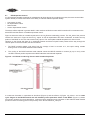
Figure 9 shows the effect of unstable superheat on the CO2/R134a condensing process. The CO2 side of the process
remains the same as in Figure 8 where CO2 vapour is first de-superheated and then condensed, as before the top
portion of the BPHE on the CO2 side contains only vapour. The actual plate material temperature is around 59°C.
However on the R134a side there is no superheat present and there is liquid R134a present all the way through the
channel plate on the R134a side, this has two affects
1.
The BPHE material rapidly cools down from an average of 59°C to around -2°C, this rapid cooling creates
tearing forces on the BPHE stainless steel material.
2.
The cooling of the BPHE stainless steel material causes the BPHE material to contract (by up to 1mm), when
the EEV restores positive superheat the BPHE stainless steel material expands.
Figure 9 - CO2/R134a Condensing Process with Unstable Superheat
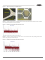
A continuous fluctuation in superheat as described (Figure 9) and the effects of (Figure 10) points 1 and 2 create
cyclic fatigue on the BPHE material and will ultimately cause premature failure of the BPHE. (Figure 11) shows
microscopic analysis from an actual failure, continuous linear expansion and contraction of the stainless steel material
produces cracks on brazing joints in the proximity of the R134a outlet/CO2 inlet port
24
BAO-104-1 AUS
Figure 10 - Microscopic Analysis of a BPHE Failure.
Figure 11 - shows site data from an actual BPHE failure it can be clearly seen that the superheat control is unstable
with continuous fluctuations around zero superheat.
Figure 11 - Graph showing unstable EEV superheat control
Figure 12 - shows the opening position of the same valve, it can be seen that the valve operating position is also
erratic, moving from fully closed to wide open.
Figure 12 - Graph showing unstable EEV Opening Position.
BAO-104-1 AUS
25
Figure 13 below shows the ideal superheat control of the EEV.
Figure 13 - Graph showing stable EEV Superheat.
ATTENTION!
Failure to maintain stable superheat will void all warranty on the BPHE, BITZER Australia reserve the right to
request periodic graphical data in the event of BPHE failure.
9.8
Piping Recommendations for EEV
Figure 14 shows the recommended position of the EEV relative to the inlet port. The EEV should be mounted in the
horizontal position relative to the inlet connection, with a straight pipe in between. The pipe between the EEV and the
BPHE inlet should be between 150mm-300mmlong or with a ratio of pipe length to pipe inner diameter of 10-30.
Figure 14 - Recommended Positions for EEV
9.9
Ancillaries BPHE [OPTIONAL] HOT WATER [HEAT RECLAIM UNIT]
BITZER CO2 Hybrid Racks are available with (OPTIONAL)] HOT WATER BPHE. This consists of a Dual Wall Stainless
Steel Brazed Plate Heat Exchanger engineered to application. The Dual Wall BPHE is intended for potable water
applications. NOTE: Water mark level 1. Certificate of conformity AS/NZS 3498:2009 CERTIFICATE No. 23131.
26
BAO-104-1 AUS
9.10
Water Connection to the HOT WATER BPHE. (Heat Reclaim Unit)
Installation:
Of water plumbing connection for a dedicated Hot Water circuit to the (OPTIONAL) HOT WATER BPHE.
Ensure that the refrigeration contractor/s has successfully pressure tested / leak tested the HOT WATER BPHE prior to
installation of plumbing [water] circuit.
The HOT WATER BPHE Ø1-1/4” MBSP water connections are to be connected counter flow to the refrigeration fittings
by a registered, licensed Plumber. We recommend that additional BSP sockets/valves be installed within the water
circuit for periodic water circuit cleaning purposes.
The maximum allowable connection load is 260 Nm Torque with a maximum Bending Moment of 87 Nm. to the
Ø1-1/4” MBSP Water fitting.
Ensure that all interconnecting plumbing (water pipes) are structurally secured before and after the BPHE.
9.11 Cleaning of the HOT WATER BPHE.
Thanks to the normally high degree of turbulence in the BPHE there is a self-cleaning effect in the channels. However
in some applications the fouling tendency can be very high. e.g. when using extremely hard water at high temperatures.
In such cases it is always possible to clean the exchanger by circulating an approved cleaning liquid. [CIP Cleaning
In Place] Use a tank with weak acid solution 5.0% phosphoric acid or if the exchanger is frequently cleaned a 5.0%
solution of oxalic acid. For optimum cleaning the cleaning solution flow rate should be minimum 1.5 times the normal
flow rate, preferably in a back flush mode. After use do not forget to rinse the exchanger carefully with clean water. A
solution of 1-2% sodium hydroxide (NaOH) or sodium bicarbonate (NaHCO) before the last rinse ensures that all acid
is neutralized. (Check PH test sample of water leaving the BPHE after the cleaning process is complete) Clean
the BPHE water circuit at regular intervals.
9.12 Ancillaries Liquid Receiver
BITZER CO2 Hybrid Racks are supplied with a CO2 rated liquid receiver, the receiver comes with 50mm insulation and
is encapsulated in a metal enclosure. All vessels are manufactured to AS1210. Figure 15 shows technical details for
the different type of the receivers.
Figure 15 - B30-245 Horizontal Liquid Receiver CO2 Colorbond Metal Clad and insulated.
BAO-104-1 AUS
27
1.
2.
3.
Two of the Frost Shield [Perspex viewing elements] are supplied within the accessories carton. Gently insert one
Frost Shield viewing element horizontally into the top sight glass and the other into the middle sight glass.
One of the HENRY E-9224 liquid level sensors is supplied within the accessories carton. Gently insert horizontally
the liquid level sensor into the bottom sight glass and wire to switchboard/control system.
NOTE: It is imperative that the Liquid level Alarm sensor be tested during commissioning and periodically when
general maintenance occurs.
9.13 Ancillaries/Liquid Level Alarm
• A low level liquid alarms are generated by a HENRY E-9224 liquid level sensor the switch is mounted horizontally
in the bottom receiver sight glass (switch locates on O ring see Figure 16). The switch is nonintrusive and can be
serviced without pumping down the receiver.
• The liquid level alarm probe is supplied loose within the accessories carton and must be installed into the
bottom liquid receiver sight glass prior to, charging the system with refrigerant.
Figure 16 - Liquid Level Switch Details (Disassembled View).
Check and Test-function of the low level Alarm probe during Commissioning.
Figure 17 - Liquid Level Switch Wiring Details
Voltage: 24V AC/DC
Rating: 0.5Amp
Contact When liquid present: 9424 N/C 9424A N/O
Min/Max Fluid Temp Range: -40°C to 98°C Working Pressure: 8273kPa
WARNING!
All electrical wiring should be carried out by qualified persons and in accordance with AS300 or equivalent
standard in the country of installation.
28
BAO-104-1 AUS
9.14 Ancillaries/Filter Driers & Moisture
The solubility of water in CO2 vapour is considerably lower than in other refrigerants, as a consequence a relatively low
moisture content can freeze out of the refrigerant and block control valves. Excessive moisture can also lead to a buildup of organic acid as the moisture reacts with both the CO2 and the POE oil. Therefore all BITZER CO2 DX Hybrid racks
come fitted with a generously sized liquid drier complete with 2 x 100% molecular sieve driers cores supplied loose.
The drier shell is installed at the rear, right hand end of the rack encased in PVC tubing complete with urethane insulation.
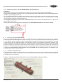
1. Upstream of the Drier Shell is a service Charging / Drain Post Valve Ø3/8”. See FIG 18
2. Upstream of the Drier shell is a Liquid line Three Way Ball Valve. See FIG 18
3. The Liquid Line can be temporarily diverted along the Liquid line By-Pass line during Drier changes. This means
that the system can be fully functional, during liquid line Drier Core replacement.
4. Please note that the driers cores are supplied loose within the accessories carton and should be installed as part
of the commissioning. See commissioning section …..
5. The Ø3/8” Post valve can also be employed for reclaim of residual CO2 refrigerant from the Drier Shell cavity prior
to Drier core changes.
Figure 18 - Liquid Line Drier (End view showing insulated cover) Figure 18A - Liquid Line Drier
3-Way Ball Valve
Liquid Line Drier
By-Pass circuit
Ø3/8” Service Valve
Recommended for
System Evacuation and
System Charging.
ATTENTION!
Only fit 100% molecular sieve driers when replacing liquid drier cores, excessive moisture content in the CO2
will lead to a build-up of organic acid.
BAO-104-1 AUS
29
9.15 Ancillaries Suction Drier /Suction Accumulator
BITZER CO2 Hybrid racks are equipped with a single core Suction Drier / Suction Accumulator Vessel. This is located
at the back of the unit within a metal cradle at the rear right hand end of the rack frame assembly.
1. The Suction Drier / Suction Accumulator vessel is Colorbond metal clad and insulated.
2. There is a removable metal insulated cover at the suction inlet end of the vessel. (Drier Shell End Plate Access)
See Figure 19
3. The insulated Individual Suctions lines along the top of the vessel are seamless stainless steel, sized to each
specific compressor.
4. Please note that the suction felt is not fitted when the rack is supplied and should be installed as part of the
commissioning. The suction felt should be removed after commissioning in order to avoid excessive pressure drop
through the filter.
5. Burnt out cores should be installed in the event of a compressor burn out or high moisture content.
6. A Service valve Ø1/4”MSAE is connected upstream of the Suction Drier / Suction Accumulator to assist with
changing drier cores.
Figure 19 - Suction Drier/Suction Accumulator vessel Schematic
1-Core Drier Shell End Plate Cover Access. This End.
Figure 19A - Suction 1-Core Drier/Accumulator Vessel Schematic
30
BAO-104-1 AUS
9.16 Ancillaries/Suction Superheaters
Due to the high solubility of CO2 and POE oil it is essential that the compressor crankcase is kept above 20°C. Low
crankcase temperatures will allow the high density CO2 to dilute into the oil, leading to compressor failure.
The BITZER CO2 Hybrid racks use several methods (depending on generation) to superheat the return CO2 suction
vapour, superheating the suction vapour raises the compressor discharge temperature, which in turn raises the oil
temperature.
Although there is a slight decrease in COP with the additional increase in suction superheat, the decrease is less than if
one were to use an external heater (additional parasitic load) to maintain crankcase temperature.
9.17 Suction Superheating
ATTENTION!
The set points listed below are advisory as each system varies depending on design conditions. Operation should be
checked to ensure that the crankcase temperature operates between 20°C and 30°C.
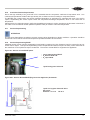
9.18 Suction Superheating BPHE
Additional suction (return vapour) superheating is achieved by passing CO2 High Pressure Liquid in counter flow to CO2
suction return vapour. This style of superheating is less complicated and does not require as many control solenoids as
the mass flow of CO2 liquid and vapour is balanced. The suction re-heat BPHE is engineered to application
Figure 20 - Suction re-heat BPHE photo
Sucton Superheating BPHE.
CO2 Suction Side and
CO2 Liquid Side.
Liquid line by-pass Solenoid.
Figure 20A - Suction R-Heat BPHE (Engineered to Appliction) Schematic.
Liquid line by-pass Solenoid Valve
Set points:
Solenoid: On -5°C Off -8°C
BAO-104-1 AUS
31
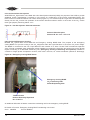
9.19 Ancillaries/Hot Gas Injection
All BITZER CO2 Hybrid racks come fitted with a Hot Gas Injection solenoid (HGIS), the purpose of the HGIS to provide
additional suction superheating if required or in the event of a malfunction of the suction superheater BPHE. The
HGIS consist of a solenoid with two non-return valves (Figure 21). The solenoid injects hot gas from the discharge line
directly into the CO2 suction line upstream of the suction Drier/Accumulator vessel. In the event of the CO2 suction
return gas (vapour) remaining below -15°C
Figure 21 - Hot Gas Injection Solenoid Schematic.
Solenoid Valve Set point
Solenoid D: On -15°C Off -10°C
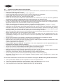
9.20 Ancillaries/Emergency Cooling
BITZER CO2 Hybrid racks come fitted with an Emergency Cooling BPHE fitted. The purpose of the emergency
cooling BPHE is to provide cooling to the CO2 refrigerant within the Liquid Receiver in the event of a power outage.
The BPHE is connected to the CO2 Liquid Receiver and includes a Tx Valve. R134a TUAE mechanical expansion
valve, (R134a is standard other refrigerants valves available on request) the liquid line and suction line on the R134a
require connecting to a dedicated condensing unit, (Emergency Cooling Condensing Unit Optional) available in
3 Phase or Single phase Compressor versions, each with a twin fan, air cooled condenser (vertical air discharge).
Figure 22 - Emergency Cooling BPHE Photo.
Emergency Cooling BPHE.
CO2 Condensing Side.
R134a Evaporating Side.
TX Valve R134a
Danfoss Externally Equalised
No. 7# Orifice
An additional HP switch is fitted to control the condensing unit for the emergency cooling BPHE.
HP Switch 3 Function: Emergency Cooling BPHE Condensing unit Control
Cut in 3800kPa
Cut out3600kPa
32
BAO-104-1 AUS
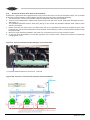
Figure 22A - Location of PRV’s on Rack. [Solenoids shown without Coils
fitted.]
High Pressure
High Pressure
Solenoid Vent Line. Liquid Receiver
Relief Valve
HP Bleed.
No.1.#
High Pressure
Liquid Receiver
Relief Valve
No.2.#
High Pressure High Pressure
Discharge line LH. BPHE Cascade
[After Oil Sep.] Condenser.
Relief Valve.
Relief Valve.
High Pressure
RH. BPHE Cascade
Condenser.
High Pressure
Liquid line
[After Drier.]
Relief Valve.
Relief Valve.
Low Pressure
Solenoid Vent Line.
LP Bleed.
3-Way Ball Valve.
To switch from Liquid Receiver
Relief valves
No.1 or No.2
Low Pressure
Transducer Connection
Ø1/4”MSAE.
High Pressure
Transducer Connection
Ø1/4”MSAE.
BAO-104-1 AUS
33
9.22 Ancillaries Transducer Points
BITZER CO2 Hybrid come with suction and discharge transducer post valves. Please note that the actual transducers are
not part of the rack scope of supply (Transducers by others). The suction transducer post valve is connected the main
suction header, the discharge transducer post valve is connected to the CO2 liquid receiver.
9.23 Ancillaries Emergency Vent Solenoid (EVS)
The BITZER CO2 racks come fitted with additional HP switches to control emergency vent solenoids. Emergency Vent
Solenoids are included within the part of the scope of supply of the rack and should be relocated outdoors by the
contractor/installer in the vicinity of the relevant main pressure reliefs valves. No additional pipework should be fitted on
the outlet of the EVS as in the event of CO2 been released dry ice will form at the point of expansion.
The purpose of the EVS is to relief pressure in the suction header and or the CO2 liquid receiver before the pressure
builds-up and the PRV’s are activated.
9.24 Ancillaries/Pressure Switches
All compressors come fitted with mechanical Low Pressure (LP) and High Pressure (HP) safety switches.
Recommended Settings Only
LP
Cut in 1200kPa
Cut out
560kPa
HP
Cut in 3200kPa
Cut out
3950kPa
Figure 23 - Additional System Pressure Switches.
High Pressure
Control KP6
HP Safety.
[System.] ①
High Pressure
Control KP6
HP Safety.
[Emergency
Cooling Unit ②
High Pressure
Control KP6
HP Bleed. ③
Low Pressure
Control KP5
LP Safety.
[System.] ④
Low Pressure
Control KP6
LPM Bleed
The additional system pressure switches are located at the right hand end of the unit frame. Each pressure control has
a dedicated isolation service valve for service purposes.
1. 2. 3. 4. 5. 34
The High Pressure safety Control is for Rack Safety.
The High Pressure (Emergency Cooling Unit) control is to operate the Emergency Condensing Unit.
The High Pressure safety Control (HP Bleed) is for the HP Bleed Solenoid Valve.
The Low Pressure safety Control is for Rack Safety
The Low Pressure safety Control (LP Bleed) is for the LP Bleed Solenoid Valve.
BAO-104-1 AUS
9.25 Suction and Liquid Headers
BITZER CO2 Hybrid Racks come fitted with six stub or eight suction and liquid headers (2 compressor racks have four
stub headers fitted as standard). The headers are encased in 225mm PVC tubing complete with urethane insulation
(Figure 24) to reduce condensation.
Figure 24 - Suction & Liquid headers
The dual Suction - Liquid header is specially designed for BITZER DX CO2 systems. Both headers (Suction and Liquid
headers) are fully sealed within the one PVC Insulated, enclosure providing compact, robust design. The Suction (Return
Vapour) Inlet connections are located on the top of the enclosure and the Liquid outlet connections are located at
the bottom of the enclosure with external pipework facing upwards. The dual suction headers are available in three
combinations.
For 2 Compressor Racks only: 4 x Suctions Ø 7/8” and 4 x Liquids Ø7/8”.
For 3 or 4 Compressor Racks: 6 x Suctions Ø 7/8” and 6 x Liquids Ø7/8”.
For 3 or 4 Compressor Racks: 8 x Suctions Ø 7/8” and 8 x Liquids Ø7/8”.
NOTE: Other combinations/sizes can be ordered as special applications.
1. 2. 3. The Suction return Inlets consist of 4, 6 or 8 stubs of Ø7/8” refrigeration pipe. Each complete with system ball valves
with non-return valve (NRV) bypass. Suction stubs have an additional post valve fitted. This arrangement allows
for the pumping down and evacuation of the field evaporators to be carried out from the rack.
The liquid Outlets 4, 6 or 8 stubs of Ø7/8” refrigeration pipe. Each complete with system ball valves with non-return
valve (NRV) bypass.
The dual header design also provides additional Suction Superheating and Liquid Sub-Cooling with its internal pipe
network.
Figure 24A - Suction and Liquid headers (Insulated)
For Connection and operating instructions of the ball valves. See Figure 25. Note: Ensure that all site pipe work is
structurally self-supported, prior to connecting to the BITZER CO2 Hybrid Rack.
BAO-104-1 AUS
35
Figure 25 - Connection & Operating Instructions for Ball Valves
Figure 26 - Connection & Operating Instructions for 3- Way Ball Valves
The three way ball valves are primarily located;
• The Discharge line upstream of the Hot Water BPHE (When HW is BPHE fitted)
• The Discharge line prior to the Air Cooled De-Superheater.
• The Liquid Line upstream of the Liquid line By-Pass and Drier Shell.
• The liquid Receiver Pressure Relief Valves.
Notes:
• The 3-way valves do not require Non- Return Valves (Check valves) in the current configurations.
• For 3-Way Valve Brazing (Soldering) instructions See Figure 26.
36
BAO-104-1 AUS
10. Commissioning/Pressure test
The entire system should be pressure tested prior to the evacuation process, the pressure test should be carried out
with Dry Nitrogen, in accordance to relevant Australian / New Zealand standards.
DANGER!
Under No circumstances is Oxygen or other industrial gases to be introduced.
Do-not add HFC refrigerant as a leak indicator.
WARNING!
All work to be carried out to the relevant Standards by licensed accredited personal.
Ensure that the test pressure does not exceed 2500kPa on the low side and 4000kPa on the high side.
Test / Inspect all components / connections for leaks. Employ the soapy water method of leak detection to system
joints-junctions while system is at test pressure. We also recommend the use of quality electronic CO2 Leak detectors
to ensure system integrity.
Warning: Electronic CO2 leak detectors can/may register CO2 presence in the expanded polyurethane foam
(insulation) within the Headers / BPHE Enclosures / Pressure Vessels Insulation.
When the pressure test/s are completed record findings.
When the pressure test/s are completed reduce the system pressure to a safe holding pressure, recommend 500 kPa.
BAO-104-1 AUS
37
10.1 Commissioning/Evacuation and Dehydration.
The BITZER CO2 Hybrid rack requires a minimum evacuation of 500 microns, we therefore recommend the following:
• Employ the Triple Evacuation Process.
• Evacuate with two-Stage vacuum pump/s sized to application.
• Provide new (approved) vacuum pump oil to the vacuum pump/s prior to evacuation.
• Employ Ø3/8” hoses [minimum size.] to both high and low sides of system.
• Ensure that all circuits of the CO2 system are all evacuated.
• Ensure that the Compressors and the Oil Separator/Reservoir are drained of oil prior to evacuation. [Label all
Compressors and the Oil Separator/Reservoir stating that they are drained of Oil]
• Ensure that all Solenoid valves are fully open during the evacuation process. This can be achieved by energising
the coils or replacing them with coil magnets during this process. [Important: Replace any coil magnets with the
appropriate Solenoid coil/s once evacuation process is fully completed]
• Ensure that the Electronic TX valves are fully open during the evacuation process.
• Employ accurate gauges for measuring vacuum e.g. Digital vacuum gauge (correctly calibrated / certified)
• Commence the 1st evacuation. During this initial process, Test vacuum to check for inward leaks. During initial
evacuation. Leave vacuum to stand for a period and record vacuum findings. If pressure rises rapidly showing
a possible inward leak. Evacuate different sections one at a time to determine leak source. Once leak is located
and fully repaired, pressure test / leak test system prior to recommencing evacuation.
• Option on larger plants isolate sections of the refrigeration plant and Evacuate different sections one at a time or
employ several vac pumps one on each section of the system.
• During initial evacuation, open the 2-Stage vacuum pump/s gas ballast valve to exhaust/remove any noncondensable’s entering the vac pump. Once a low vacuum is approaching close the Ballast valve to achieve
lowest vacuum.
• Once the first evacuation is successfully completed. [Record findings within commissioning report]
• Ensure that the vacuum testing instruments are disconnected or isolated.
• Break the 1st vacuum with dry nitrogen to a positive pressure. Install all system drier/filter cores between the first
and the second evacuation. [Keep any exposure of the
system to atmosphere to a minimum]
• Install BITZER approved BSE60K refrigeration oil to each compressor and Oil Separator/Reservoir
between the first and the second evacuation.
• Commence 2nd evacuation process and reinstate the vacuum testing instruments. Activate heaters.
• Once the 2nd vacuum is achieved [Record findings within commissioning report.]
• Ensure that the vacuum testing instruments are again disconnected or isolated.
• Break the 2nd vacuum with refrigeration grade R744 CO2 vapour only to a positive pressure. [We recommend
charging the vapour R744 CO2 through a drier shell with a drier core/s fitted.]
• Commence 3rd evacuation process. And reinstate the vacuum testing instruments.
• Once the 3rd [final.] vacuum is achieved [Record findings within commissioning report.]
• The system is now ready for R744 CO2 refrigerant charging. [System must be charged from a vacuum with
vapour R744 only.]
For locations of Evacuation Connections refer List below and Figure.1 BITZER CO2 Hybrid Rack Schematic .
1.
2.
3.
4.
38
The Liquid line Ø3/8” MSAE Post valve upstream of the 2-Core liquid line Drier.
The Suction Line Ø3/8” MSAE Post valve upstream of the Suction Drier/Accumulator vessel.
The Ø1/4” MSAE Post valves at the Suction header. [One per Suction Inlet.]
The Compressor service valve Ø1/4” MSAE connections. [DL and SL Valves]
BAO-104-1 AUS
10.2 Commissioning/Oil
Oil type: BITZER BSE 60K (POE)
ATTENTION!
The POE oils used in the BITZER CO2 Hybrid rack is hydroscopic, when exposed to the atmosphere it absorbs moisture.
Excessive moisture in the CO2 can lead to a build-up of organic acids as the free moisture reacts with both the POE
and the CO2
• Do not reuse drained oil that has been exposed to the atmosphere.
• The minimization of system internals, exposure to atmosphere.
• The use of 100% molecule sieve driers only.
• Check operation of crankcase heaters during evacuation.
10.3Commissioning/Controls
Special attention must be taken in the control strategies used to control the BITZER CO2 Hybrid rack and the high stage
rack: the very minimum we require the following.
• The use of electrical interlocks to prevent the BITZER DX Hybrid CO2 rack operating without the high stage rack
operating.
• Evaporator and fans should be staged off in the event of the suction pressure reaching 2200kPa.
• Evaporators and fans should be staged back on after a power outage.
10.4
Commissioning/Starting Up and Charging
WARNING!
The following should only be carried out by suitably qualified refrigeration technician. Ensure that all gauges are accurate
and hoses are in good condition and have sufficient pressure rating.
A Risk Assessment and SOP should be completed before this work is carried. Appropriate PPE must be worn.
The high stage system and emergency cooling unit must be commissioned with all safety and control circuits proven.
All safeties and control circuits on the BITZER CO2 Hybrid Rack should be set and tested.
Energise the crankcase heaters and ensure that the oil temperature is between 35°C to 40° and that there is sufficient
oil in the compressors and the oil separator.
The BITZER DX Hybrid CO2 unit should be charged with refrigeration grade R744, CO2 with a moisture content
of 10 parts per million or less.
Extreme care must be taken when charging the system with R744
From a vacuum: Only Vapour Charge R744 Refrigerant into The Refrigeration System.
1. Connect the refrigerant charging line into the system 3/8” MSAE Charging Service Valve. This ensures refrigerant
charging through the systems dual core liquid line drier.
2. We recommend an additional 100% molecular sieve driers/shell be installed in the charging line to further ensure
that the system is charged with Dry R744.
3. This system must be vapour charged with R744 until the system pressure is above 600kPa
4. Only when the entire system is at 500kPa or greater can you then begin to Liquid Charge R744 CO2 into the Liquid
Line Charging Service valve Ø3/8” MSAE. And the Liquid Receiver, once an overall all system pressure of above
600kPa has been reached.
5. Continue charging liquid into the receiver until a level is clearly visible in the second sight glass. Once this level has
been reached turn on one sub system at a time, do not turn to many sub systems at once as this can lead to a rapid
rise in pressure.
6. Add additional refrigerant as required.
7. Vapour can be charged into the liquid receiver, wet gas return or dry suction.
8. Liquid can be charged in to the liquid receiver or liquid line.
9. Ensure that the system is sufficiently charged with R744, CO2
WARNING!
CHARGING LIQUID CO2 INTO THE SYSTEM AT PRESSURES BELOW 500kPa CAN LEAD TO THE FORMATION
OF CO2 IN A SOLID FORM (DRY ICE).
BAO-104-1 AUS
39
WARNING!
Do not overcharge system with refrigerant.
ATTENTION!
Avoid high cycling rates on compressors.
ATTENTION!
Switch off compressors immediately, upon exceeding the application limits or in case of abnormal conditions (e.g. wet
operation). Only switch compressors back on when pressure levels are stabilised or after correcting any faults.
ATTENTION!
Avoid rapid pressure pull down inside the crankcase when starting and during operation, as this will lead to oil
foaming and result in a lack of lubrication.
10.5Commissioning/Checks
The following should be checked and verified as part of the commissioning procedure.
ATTENTION!
BITZER Australia reserve the right to request one week’s running data from newly commissioned sites as
proof that the BITZER CO2 Hybrid rack is operating within its design envelope. Failure to do so may result in
voiding warranty on certain componentry
•
•
•
•
•
•
•
•
40
Set all system pressure (compressor safety) controls as described in section 6.
The superheat operation of the High Stage Cascade EEV must be checked and verified that the conditions described
in section 6.12 do not exist.
Operation of suction superheater should be verified and compressor crankcase, discharge temperature and suction
temperature should be logged.
The mains power to the plant should be turned off to the BITZER CO2 Hybrid Rack. The operation of the Emergency
Cooling BPHE needs to be checked.
Operation of the air cooled de-superheater should be checked, continuous cycling of the de-superheater fans
should be avoided. All de-superheater fans should be off when the CO2 outlet vapour temperature reaches 12°C.
Case defrost should be set so that excessive loads are created.
Operation of low liquid level alarm should be verified
Cycling frequency of compressors should be checked, compressor starts should not exceed eight starts per hour,
min operating time two minutes
BAO-104-1 AUS
11.
Commissioning Sheet. #
BITZER COMMISSIONING DATA SHEET
DESCRIPTION
BITZER RACK SERIAL NO.
BITZER COMPRESSOR MODEL NO.
BITZER COMPRESSOR SERIAL NO.
COMPRESSOR PRESSURE RELIEF VALVE (FITTED)
COMPRESSOR SUMP HEATER (FITTED & CHECKED)
COMPRESSOR RUN AMPS
RWB
SUCTION PRESSURE
SUCTION TEMP.
SUCTION TEMP. Hot Gas Injection Solenoid
SUCTION REHEAT bphe by-pass Solenoid setting
DISCHARGE PRESSURE
DISCHARGE TEMP. Compressor
DISCHARGE TEMP. Main Discharge Manifold
DISCHARGE TEMP. Entering Air Cooled De-Superheater
DISCHARGE TEMP. Exiting Air Cooled De-Superheater
DISCHARGE TEMP. Entering Liquid Receivers Internal Sparge Manifold
VALUE
25 Bar
√ or X
Amp.
Kpa
ºC
ºC
ºC
Kpa
ºC
ºC
ºC
ºC
ºC
%
√ or X
√ or X
√ or X
HIGH STAGE SYSTEM 134a
HIGH STAGE SYSTEM R134a CHECK FOR OPERATION/COMMISSIONING
HIGH STAGE SYSTEM R134a SUCTION SUPERHEAT RIGHT HAND SUCTION LINE
HIGH STAGE SYSTEM R134a SUCTION SUPERHEAT LEFT HAND SUCTION LINE
HIGH STAGE SYSTEM R134a AKV OR EEV SETTING
LIQUID SEPARATION VESSEL R134a LEVEL
LIQUID SEPARATION VESSEL R134a SHP LEVEL PROBE
LIQUID TEMP. R134a ENTERING BPHE
LIQUID TEMP. R134a EXITING RIGHT HAND SIDE OF BPHE
LIQUID TEMP. R134a EXITING LEFT HAND SIDE OF BPHE
√ or X
ºC
ºC
ºC
%
√ or X
ºC
ºC
ºC
SUCTION PRESSURE
SUCTION TEMP.
DISCHARGE PRESSURE
DISCHARGE TEMP.
LP CONTROL SETTING
HP CONTROL SETTING
COMPRESSOR OIL LEVEL
BAO-104-1 AUS
/
/
/
/
/
/
/
/
Kpa
Kpa
Kpa
Kpa
Kpa
Kpa
Kpa
Min.
%
%
bar
LP CONTROL SETTING (Compressor)
HP CONTROL SETTING (Compressor)
LP CONTROL SETTING (Rack)
LP CONTROL SETTING (LP Bleed)
HP CONTROL SETTING (RACK)
HP CONTROL SETTING (LP Bleed)
HP CONTROL SETTING (Emergency Cooling)
ANTI-SHORT CYCLING SETTING
COMPRESSOR OIL LEVELS
OIL SEPARATOR / RESERVOIR LEVEL
TEMPRITE PRESSURE DIFFERENTIAL INDICATOR READING
TRAX OIL LEVEL CONTROL CHECK
LIQUID RECEIVER LIQUID LEVEL
LIQUID LEVEL OPTICAL LEVEL SENSOR TEST
LP TRANSDUCER # CHECK
HP TRANSDUCER # CHECK
REMOTE EMERGENCY BACKUP CONDENSING UNIT
BITZER COND. UNIT MODEL NO.
BITZER COND. UNIT SERIAL NO.
COMPRESSOR RUN AMPS
RWB
COMPRESSOR COMPRESSOR COMPRESSOR COMPRESSOR
NO. 1
NO. 2
NO. 3
NO. 4
Amp.
Kpa
ºC
Kpa
ºC
Kpa
Kpa
%
/
/
41
12. Service and Maintenance Program:
BITZER Australia recommends that the following service and maintenance checks should be carried out as a minimum
requirement.
ATTENTION!
Failure to comply with the schedule listed below and to maintain accurate service and maintenance records may result
in premature failure and poor operation of the BITZER CO2 Hybrid rack and will affect any warranty claims.
First 100 Hours of operation:
• Change compressor oil.
• Clean compressor oil filter and magnetic plug.
• Replace main oil strainer. [replace oil Filter with new approved model] BITZER COS-Oil Separators. If Temprite Oil
separator employed check pressure differential indicator and replace Temprite cartridge with spare.
• Take oil sample for analysis.
• Check evaporators (frost patterns)
• Check high stage rack system.
• Log system/s operating parameters. (Both DX CO2 and High stage Plant.)
• Check operation of emergency cooling unit.
• Check for abnormal noise and vibration.
• Check compressor crankcase temperatures.
• Check all refrigeration unit pipe clamps [Stauff Clamps.] for tightness.
• Check Air Cooled De-Superheater.
• Check electrical cables for tightness
• Check Electrical Switchboard/s for hot spots [ Laser – Thermal – Sensor]
• Leak test plant.
• Record all 100 hour maintenance checks.
Monthly
• Check system operating conditions.
• Check operation of emergency cooling unit.
• Check for abnormal noise and or vibration.
• Check compressor oils for bubbles, cleanliness and levels.
• Check CO2 refrigerant level (Liquid Receiver).
• Check for oil leaks
• Check operation of EEV’s (operation and superheat setting.)
• Check operation of suction superheat (BPHE) control.
• Log system/s operating parameters
• Check electrical cables for tightness
• Leak test plant.
• Record all monthly maintenance checks.
Quarterly
• Check system operating condition.
• Check operation of emergency cooling unit where applicable. [Check cleanliness of the Emergency Cooling Unit
Condenser Coil.]
• Check operation of Remote Air Cooled De-Superheating Unit where applicable. [Check cleanliness of Coil. Check
fan Motors. Check operation]
• Check for abnormal noise and or vibration.
• Check compressor oils for cleanliness and levels.
• Check CO2 refrigerant level (liquid receiver).
• Check for oil leaks.
• Check operation of EEV’s (operation and superheat setting.)
• Check operation of suction superheat (BPHE) control.
• Log system/s operating parameters.
• Check all pipe clamps for tightness.
• Check electrical cables for tightness.
• Leak test plant. Record all monthly maintenance checks.
• Record all quarterly maintenance checks.
42
BAO-104-1 AUS
12.
Service and Maintenance Program: Continued.
Annually
• As per monthly check with the additional check listed below.
• Change compressor oil.
• Clean each compressors oil filter and magnetic plug.
• Replace main oil strainer. [replace oil Filter with new approved model] BITZER COS-Oil Separators. If Temprite Oil
separator employed check pressure differential indicator and replace Temprite cartridge with spare.
• Replace liquid line drier cores.
• Take oil sample for analysis.
• Check operation of safety circuits.
• Check high stage rack system.
• Check all refrigeration unit pipe clamps [Stauff Clamps.] for tightness.
• Check operation and calibration of plant room CO2 refrigerant detection system.
• Check plant room ventilation system.
• Record all annual maintenance checks.
13.
Drawings
Figure 27 - BITZER 3 Compressor CO2 DX Hybrid Low Temperature Rack.
- Frontal view showing right hand side.
BAO-104-1 AUS
43
Figure 28 - BITZER 3 Compressor CO2 DX Hybrid Low Temperature Rack.
- Frontal view showing Left hand side with optional [Integral Emergency Cooling Unit and rear mounted Integral
Air Cooled De-Superheater.]
Figure 29 - BITZER 3 Compressor CO2 DX Hybrid Low Temperature Rack.
- Side view showing Right hand side.
44
BAO-104-1 AUS
Figure 30 - BITZER 2 Compressor CO2 DX Hybrid Low Temperature Rack Dimensional drawing
.
Note: Dimensions are subject to change for special [non-standard.] applications.
BAO-104-1 AUS
45
Figure 31 - BITZER 3 or 4 Compressor CO2 DX Hybrid Low Temperature Rack Dimensional drawing.
Note: Dimensions are subject to change for special [non-standard.] applications.
46
BAO-104-1 AUS
14.
R744 CO2 Pressure Temperature Chart
BAO-104-1 AUS
47
15.
R744 CO2 Operating Window.
The R744 CO2 operating window displays the fact where R744 CO2 refrigerant must be initially charged as vapour only
to reduce the risk of the refrigerant forming internally as DRY ICE.
48
BAO-104-1 AUS
16. R744 CO2 Material Safety Data Sheet.
Safety Data Sheet
Version : 1
Product : R744
MSDS Nr : 300-00-2008BOC(A)
Date : 13/12/2005
BOC, UNITED KINGDOM
1.
•
•
•
IDENTIFICATION OF THE SUBSTANCE/PREPARATION AND OF THE COMPANY
Product name R744
Chemical formula CO2
Company identification see heading and/or footer
2.
•
•
•
•
COMPOSITION/INFORMATION ON INGREDIENTS
Substance/Preparation Substance.
Components/Impurities Contains Carbon dioxide {EINECS No. 204-696-9}
CAS Nr 124-38-9
EC Nr (from EINECS) 204-696-9
3. HAZARDS IDENTIFICATION
• Hazards identification Liquified gas
• In high concentrations may cause asphyxiation.
4.
•
•
•
•
•
•
FIRST AID MEASURES
Low concentrations of CO2 cause increased respiration and headache.
High concentrations may cause asphyxiation. Symptoms may include loss of mobility/consciousness.
Victim may not be aware of asphyxiation.
Remove victim to uncontaminated area wearing self-contained breathing apparatus. Keep victim warm
and rested. Call a doctor. Apply artificial respiration if breathing stopped.
Skin/eye contact:
- In case of liquid burn, spray with water for at least 15 minutes. Apply a sterile dressing
- Immediately flush eyes thoroughly with water for at least 15 minutes
- Obtain medical assistance
Ingestion is not considered a potential hazard of exposure.
5. FIRE FIGHTING MEASURES
• Specific hazards:
- Exposure to fire may cause containers to rupture/explode.
- Non flammable
- Hazardous combustion products
- Non-suitable extinguishing media
- All known extinguishants can be used
• Specific methods If possible:
- Stop flow of product.
- Move away from the container and cool with water from a protected position
BAO-104-1 AUS
49
17. BITZER BSE 60K OIL Material Safety Data Sheet.
MATERIAL SAFETY DATA SHEET
According to 91/155/EC
Printing date 23.03.2006 Reviewed on 23.03.2006
Identification of substance:
• Product details:
• Trade name: BSE60K OIL
• Application of the substance / the preparation: Lubricant
• Manufacturer/Supplier:
FUCHS EUROPE SCHMIERSTOFFE GMBH EXPORT DIVISION
Friesenheimer Str. 15
D-68169 Mannheim
Tel: ++49 (0)621/3701-0 (Switch Board)
Fax: ++49 (0)621/3701-570
• Informing department:
- Product safety department Tel: ++49 (0)621/3701-333
• Emergency information:
- Tel: ++49 (0)621/3701-333 or ++49 (0)621/3701-0 (Switch Board)
2 Composition/Data on components:
• Chemical characterization
• Description: Mixture of synthetic base oils with additives.
- Dangerous components: R-phrases
- Triaryl phosphate 0.1-1 %
- N; R 50/53
• Additional information
- For the wording of the listed risk phrases refer to section 16.
Hazards identification
• Hazard designation:
- By handling of mineral oil products and chemical products no particular hazard is known when normal precautions
(item 7) and personal protective equipment (item 8) are kept.
• Information pertaining to particular dangers for man and environment
- This product is water polluting; see item 12.
- R 52/53 Harmful to aquatic organisms, may cause long-term adverse effects in the aquatic environment.
• Classification system
- The classification is in line with current EC lists. It is expanded, however, by information from technical literature
and by information furnished by supplier companies.
- The classification results from the Conventional Method of 1999/45/EC concerning specific data of compounds.
First aid measures
• General information:
- Change clothes and shoes contaminated or soaked by the product.
- Never put rags contaminated by the product into cloth-pockets.
• After inhalation:
- Supply fresh air; consult doctor in case of symptoms. (Eventually by inhaling the overheated product)
• After skin contact: The product is not skin irritating.
• After eye contact: Rinse opened eye for several minutes under running water.
• After swallowing: In case of persistent symptoms consult doctor.
Fire fighting measures
• Suitable extinguishing agents CO2:
- Extinguishing powder or water jet. Fight larger fires with water jet or alcohol-resistant foam.
- Use fire fighting measures that suit the environment.
• For safety reasons unsuitable extinguishing agents: Water with a full water jet.
• Protective equipment: In case of fire fighting wear self-containing breathing apparatus
50
BAO-104-1 AUS
17. BITZER BSE 60K Material Safety Data Sheet continued:
Accidental release measures
• Person-related safety precautions:
- Particular danger of slipping on leaked/ spilled product.
• Environmental protection measures:
- Inform respective authorities in case product reaches water or sewage system.
- Do not allow to enter drainage system, surface or ground water.
- Prevent from spreading (e.g. by binding or oil barriers).
- Do not allow to enter the ground/ soil.
• Measures for cleaning/collecting:
- Absorb with liquid-binding material (sand, diatomite, acid binders, universal binders, sawdust).
- Dispose of the material collected according to regulations.
Handling and storage
Handling
• Information for safe handling:
- Prevent formation of aerosols.
- Do not eat, drink or smoke when working with the product.
- Take usual precautions when handling mineral oil products or chemical products.
• Information about protection against explosions and fires:
- Do not heat up Oil to temperatures close to the flash point.
Storage
• Requirements to be met by storerooms and containers:
- No special requirements.
• Information about storage in one common storage facility: Store away from foodstuffs.
• Further information about storage conditions:
- Local regulations concerning handling and storage of water polluting products have to be followed.
Exposure controls and personal protection
• Additional information about design of technical systems:
- No further data; see item 7.
• Components with critical values that require monitoring at the workplace:
- The product does not contain any relevant quantities of materials with critical values that have to be monitored
at the workplace.
• Additional information:
- The lists that were valid during the compilation were used as basis.
• Personal protective equipment
• General protective and hygienic measures
- The usual precautionary measures should be adhered to in handling the chemicals and the mineral oil products.
- Wash hands during breaks and at the end of the work.
- Avoid close or long term contact with the skin.
- Use skin protection cream for preventive skin protection.
- Do not carry cleaning cloths impregnated with the product in trouser pockets.
• Breathing equipment: Not required.
• Protection of hands: Protective gloves and protective skin cream.
• Material of gloves
- The selection of the suitable gloves does not only depend on the material, but also on further marks of quality
and varies from manufacturer to manufacturer. As the product is a preparation of several substances, the
resistance of the glove material cannot be calculated in advance and has therefore to be checked prior to the
application.
• Penetration time of glove material
- The exact break through time has to be found out by the manufacturer of the protective gloves and has to be
observed.
• Eye protection: Safety glasses recommended during refilling.
• Body protection: Protective work clothing.
BAO-104-1 AUS
51
17. BITZER BSE 60K Material Safety Data Sheet continued:
Physical and chemical properties: General Information
• Form: Fluid
• Colour: Light yellow
• Smell: Characteristic
• Value/Range Unit Method
• Change in condition
• Melting point/Melting range: Not determined
• Boiling point/Boiling range: Not applicable or not determined
• Flash point: 286°C ISO 2592
• Decomposition temperature: Not determined
• Self-in flammability: Product is not self-igniting.
• Danger of explosion: Product is not explosive.
• Density at 20°C 1.01 g/cm³ DIN 51 757
• Solubility in / Miscibility with
• Water: Not miscible or difficult to mix
• Viscosity or Consistency-Class:
• Kinematic: at 40°C 55 mm²/s DIN 51 562
Stability and reactivity
• Thermal decomposition / conditions to be avoided:
- No decomposition if used according to specifications.
• Dangerous reactions No dangerous reactions known
• Dangerous products of decomposition:
- No dangerous decomposition products known
Toxicological information
Acute toxicity:
• Primary irritant effect:
- on the skin: No irritant effect known.
- on the eye: No irritant effect known.
• Sensitization: No sensitizing effect known.
• Additional toxicological information:
- When used and handled according to specifications, the product does not have any harmful effects according to
our actual information.
Ecological information:
• Behaviour in environmental systems:
• Mobility and bioaccumulation potential: No data available
• Eco-toxic effects:
• Remark: Harmful to fish
• Behaviour in sewage processing plants:
•
The product sinks in the sewage water on account of its high specific gravity; eventually it is able to pass the
conventional collector for light-density material.
• General notes:
- German Water Endangering Class 1 (Self-assessment): slightly hazardous for water.
- Do not allow to reach ground water, water bodies or sewage system.
- Harmful to aquatic organisms
Disposal considerations
• Product:
• Recommendation
- Must not be disposed of together with household garbage. Do not allow product to reach sewage system. When
storing used mineral oil products, ensure that the categories for waste oil and mixing instructions are observed.
• Delivery of waste oil only to officially authorized collectors.
• European waste catalogue
• 13 02 08: other engine, gear and lubricating oils
• Uncleaned packaging’s:
• Recommendation:
- Empty contaminated packaging’s thoroughly. They can be recycled after thorough and proper cleaning. Small
one-way packaging’s have to be disposed according to the local regulations. EWC 15 01 99.
52
BAO-104-1 AUS
17. BITZER BSE 60K Material Safety Data Sheet continued:
Transport information
•
•
•
•
•
•
Land transport ADR/RID and GGVS/GGVE (cross-border/domestic)
ADR/RID-GGVS/E Class: Maritime transport IMDG/GGVSea: • IMDG/GGVSea Class: - • Marine pollutant: No
Air transport ICAO-TI and IATA-DGR:
ICAO/IATA Class: Transport/Additional information:
- No dangerous good acc. to dangerous goods/ transport directions.
Regulatory information.
• Designation according to EU guidelines:
- Observe the normal safety regulations when handling chemicals or mineral oil products.
- The product has been classified and labelled in accordance with EC
- Directives until 2004/73/EC (29. ATP).
• Risk phrases:
- 52/53 Harmful to aquatic organisms, may cause long-term adverse effects in the aquatic environment.
• Safety phrases:
- Avoid release to the environment. Refer to special instructions/safety data sheets.
• National regulations
• German Water Hazard Class:
- Water Endangering Class 1 (Self-assessment): slightly hazardous for water.
Other information:
All ingredients are listed in the European Inventories. These data are based on our present knowledge. However, they
shall not constitute a guarantee for any specific product features and shall not establish a legally valid contractual
relationship. This data sheet is a safety data sheet according to 91/155/EU. For products which are not subject to
classification according to EU lists this data sheet is made on a voluntary base.
•
•
•
•
Relevant R-phrases
- 50/53 Very toxic to aquatic organisms, may cause long-term adverse effects in the aquatic environment.
Department issuing data specification sheet:
- FUCHS EUROPE SCHMIERSTOFFE GMBH Export Division
- Product Safety Department
Contact:
- Product Safety Department:
- Tel: ++49(0)621/3701-333, Mrs. Manuwald
Validity:
- With this latest edition of this MSDS all former editions are invalid.
BAO-104-1 AUS
53
18. Risk Assessment Documentation.
Work Activity:
Transport, lifting
Site / Location:
Onsite location
Those at Risk
Y/N
Comments - enter names of general groups
Contractor:
Y
Installation, personnel and Assistants
Other workers:
Y
General Public
N
Comments: The package is supplied shrink wrapped on an export treated wooden skid and requires installing in its final position. No-one under the age of 18 will undertake lifting or
slinging operations unless directly and closely supervised by a componenet person.
HAZARDS
1.
2.
3.
4.
5.
6.
7.
8.
9.
Collision of moving crane, host, forklift truck or lifting other device with people or plant.
Collision of crane boom, hook, block or other moving part with people or plant
Collision of suspended load with people or plant
Working in windy or rainy weather or when sunshine makes observation difficult
Working at night when there is insufficient lighting to observe the full travel of the load
Dropping of load due to mechanical failure of load bearing component (crane, sling or shackle)
Dropping of load due to incorrect slinging method or use of equipment or overload of crane or sling
Trapped fingers or toes
Cuts and abrasions whilst handling chains or sling
Control Measures (existing or planned)
Details
Control
PPE:
Equipment:
Information, Instruction and
Training:
Control
1.
2.
3.
4.
5.
1.
2.
3.
1.
2.
3.
4.
5.
6.
7.
8.
9.
10.
11.
12.
13.
14.
15.
Steel toecap boots
Overalls/protective clothing
Safety helmet
Leather gloves for handling chains or slings
Safety harness (if appropriate)
Forklift
Slings, hooks (fitted with safety catches), plate clamps, eyebolts and shackles
Crane or hoist (mobile cranes must be fitted with overload warning devices)
Observe local standards and guidelines relating to lifting operations and lifting equipment and safe use of cranes
Insure that all lifting equipment including forklifts are properly maintained
Only qualified personnel should lift or install package
No-one under the age of 18 will undertake lifting or slinging operations unless directly and closely supervised by a competent person
Any good Boson or Rigger's manual with a section on rigging practices
Maintenance checklist of slings and lifting equipment
Weights of items slung and lifted should be known before lift is undertaken
Only those trained in slinging will carry out these operations
Damaged slings of lifting equipment must be discarded immediately and cut or otherwise rendered unuseable
For large and unusually shaped loads or loads with not fixed lifting points are provided, a professional rigger should be subcontracted in
addition to crane operator
The safe working load must be clearly marked on all lifting equipment and tackle. Check before use.
A competent person must plan non-routine lifts
Ropes, chains or slings should be shortened in a safe manne
Lifting tackle will be returned to appropriate storage after use
Extreme care should be taken not to trap fingers when loads are being positioned
Details
Supervision:
An experienced person who has been trained in slinging will attach the slings or direct the rigger to the appropriate lifting points.
No fixed lifting points are provided, so a competent rigging sub-contractor should be employed. The crane driver will not lead the lift.
Forklift drivers should possess relevant licences
Environment:
Lifting and slinging takes place under all conditions and weather - Important considerations are that the load is balanced and that tag lines are used to
steady and guide the load. Very windy conditions may prohibit the lift.
Procedures, documents etc:
1.
2.
3.
Communications:
Emergency action/procedures:
Access:
54
4.
5.
1.
1.
2.
3.
1.
2.
The load should be slung from correctly attached shackles - the most common failure is that of an eyebolt pulled at an incorrect angle
The load should be lifted a few inches and checked that it is stable before the full lift is attempted
When lifting operations are su-contracted to specialist, the contractor should ensure that the crane was thoroughly examined within the last
12 months, that thie accessories were thoroughly examined within the last 6 months and that both the crane dirver and banks man are
certified competent.
Observe the safety standards and other national safety regulations
Refer to relevant BITZER documentation
Lift should be supervised by suitably trained or qualified persons, radios or other suitable communication devices should be used
Observe the safety standards and other national safety regulations
Persons trained in the use of first aid should be present
Call emergency services
Access should be restricted to the area where lift is taking place, issue appropriate signage
Access to the area beneath the crane radius over which a load will pass should be prohibited to prevent a load striking a person.
Access around the crane will be controlled to prevent the crane trapping persons.
BAO-104-1 AUS
18. Risk Assessment Documentation.
Probability of Occurence
Remote = 1
Possible = 2
Frequent = 3
Hazard Severity
Minor = 1
Serious (Hospital) = 2
Major (3 days or more) l = 3
Probability of Occurence x Hazard Severity = Risk Rating (RR)
Identified Hazards (base scores on existing or planned control measures)
1. Collision with moving plant
2. Collision with moving machine parts
3. Collision with moving materials
4. Weather conditions
5. Insufficient lighting
6. Dropping loads due to mechanical failure
7. Dropping load due to misapplication of lifting equipment
8. Trapped fingers or toes
9. Cuts or abrasions
Note:
Moderate Scores:
Probability
1
1
1
1
1
2
3
2
2
3
Severity
2
2
2
2
3
1
1
2
1
1
3
2
1
1
RR
2
2
2
1
2
3
4
2
1
Thought should be given to reducing risk, but the cost and time
(1 to 5):
Substantial:
Requirements of prevention should be carefully considered and limited
Work should not be started until the risk has been reduced, for work (6 to 7) in progress, urgent action is required.
Considerable resources may have to be allocated.
Intolerable:
If unlimited resources cannot reduce risk, work will be prohibited (8 to 9)
Is risk adequately controlled using the above control measures Y / N
Y
If "No" state further action required
State further action required:
Note: This risk assessment is only valid when all control measures are in place before the work or activity commences. If the nature of the work
changes or there is a dangerous occurrence.
BAO-104-1 AUS
55
18. Risk Assessment Documentation.
Work Activity:
Pressure Testing & Evacuating
Site / Location:
Onsite location
Those at Risk
Y/N
Comments - enter names of general groups
Contractor:
Y
Installation, Personnel and Assistants
Other workers:
Y
General Public
N
Comments: The package is delivered with a holding charge of dry nitrogen, which requires releasing before additional field pipework is connected.
Care should be taken during pressure testing the entire system and during the commissioning of the package.
HAZARDS
The following hazards have been identified:
1. Risk of explosion
2. Risk of over pressure
3. Environmental pollution
Control Measures (existing or planned)
Details
Control
PPE:
1.
2.
3.
1.
2.
1.
2.
3.
4.
5.
6.
Gloves
Safety goggles
Steel toe cap boots
General tools
Calibrated gauges and test equipment
Only use dry nitrogen for pressure testing, never use Oxygen or other industrial gases as this leads to an explosion
Never add refrigerant to the test gas; environmental pollution is possible
Refer to relevant BITZER documentation
Only use calibrated gauges and equipment, use serviced regulators to control the flow of nitrogen
Continuously observe the flow and pressure of nitrogen
Only qualified personnel should install and commission the package
1.
2.
1.
2.
Work should be carried out only by qualified persons
Observe National Safety Regulations
Ensure adequate levels of ventilation
Check emergency exits
Procedures, documents etc:
1.
2.
3.
Observe the Safety Standards and National Safety Regulations
Refer to relevant BITZER documentation
AS1667
Communications:
1. Comply with site rules permits may be required
2. Familiarise yourself with plant site emergency plan
In case of leak:
1. Isolate leak (if possible)
2. If isolation is not possible, evacuate area and follow the site emergency plan
3. Treatment to injuries should be in accordance with the product data sheet
1. Access should be restricted to the area where work is taking place
Equipment:
Information, Instruction and
Training:
Control
Supervision:
Environment:
Emergency action/procedures:
Access:
56
Details
BAO-104-1 AUS
18.
Risk Assessment Documentation.
Risk Evaluation of Identified Hazards
Probability of Occurence
Hazard Severity
Remote = 1
Minor = 1
Probability of Occurence x Hazard Severity = Risk Rating (RR)
Identified Hazards (base scores on existing or planned control measures)
1. Risk of explosion
2. Risk of over pressure
3. Environmental pollution
Possible = 2
Serious (Hospital) = 2
Probability
1
1
2
1
2
Frequent = 3
Major (3 days or more) l = 3
3
1
Severity
2
3
3
2
1
RR
3
4
2
Thought should be given to reducing risk, but the cost and time
Requirements of prevention should be carefully considered and limited
Work should not be started until the risk has been reduced, for work (6 to 7) in progress, urgent action is required.
Considerable resources may have to be allocated.
Intolerable:
If unlimited resources cannot reduce risk, work will be prohibited (8 to 9)
Is risk adequately controlled using the above control measures Y / N
Y
If "No" state further action required
State further action required:
Note:
Moderate Scores:
(1 to 5):
Substantial:
Note: This risk assessment is only valid when all control measures are in place before the work or activity commences. If the nature of the work
changes or there is a dangerous occurrence.
BAO-104-1 AUS
57
18.
Risk Asssessment Documentation.
Work Activity:
Charging/Decanting Refrigerant
Site / Location:
On site location
Y/N
Those at Risk:
Comments - enter names or general groups
Y
Contractors:
Installation, Personnel and Assistants
Other Workers:
Sub-contractors, site maintenance personnel
Y
General Public
N
Comments:
When charging a system, when decanting a system, it is also very easy to overfill a recovery cyclinder. An overfilled refrigerant recovery cylinder represents a serious explosion
hazard. It is essential that proper charging and recovery procedures be observed to prevent serious incidents involving injury or accidental emission of refrigerant.
HAZARDS
The following hazards have been identified:
1. Explosion
2. Asphyxiation
3. Refrigerant liquid burns
4. Manual handling injury when moving cylinders or plant
Control
PPE:
Equipment:
Information, Instruction and
Training:
Control
Control Measures (existing or planned)
Details
1.
2.
3.
4.
5.
1.
2.
3.
4.
5.
1.
2.
3.
Safety boots with a heel, good grip and steel to cap
Overalls/protective clothing
Safety goggles
Neoprene impervious gloves
Hard hat
Refrigerant recovery pump
Scales (for recovery)
Suitable charging/transfer lines
Properly identified refrigerant recovery cylinders
Log book for recording amount charged, decanted or transferred
Wear impervious gloves to prevent refrigerant contacting the hands
Eye protection must be worn when opening any refrigeration system. As a minimum goggles are required.
Only persons experienced in handling refrigerations and with relevant licences will charge, decant refrigerant. They may have an
apprentice or assistant helping them or observing the operation.
4. Continuously and accurately weigh recovery cylinders during decanting
5. Continuously supervise charging, decanting or transferring operations
6. Secure cylinders from falling over
7. Do not trap liquid refrigerant between valves
8. Use mechanical handling equipment or follow good manual handling techniques
9. Warning signs to be erected, warning of hazards
10. Transfer lines to be made safe by marking with bunting to stop accidental collision
Details
Supervision:
Environment:
1.
1.
2.
Contractors should ensure that all persons are properly trained in handling refrigerants and have current dated handling licence
Ensure adequate levels of ventilation
Check emergency exits
Procedures, documents etc:
1.
When charging liquid refrigerant, disconnect the hoses slowly in case liquid remains in the hose (frost on hose may indicate that liquid
is still present.
Keep an accurate record of the amount of refrigerant added, decanted or transferred
2.
Communications:
Emergency action/procedures:
Access:
Environmental:
58
1. Comply with site rules permits may be required
2. Familiarise yourself with plant site emergency plan
In case of leak:
1. Isolate leak (if possible)
2. If isolation is not possible, evacuate area and follow the site emergency plan
3. Treatment to injuries should be in accordance with the product data sheet
1. Access should be restricted to the area where work is taking place
1. Disposal of waste refrigerants covered by various Environmental Protection Acts, refer to local, observe the Safety Standards and other
National Safety Regulations
BAO-104-1 AUS
18. Risk Assessment Documentation.
Risk Evaluation of Identified Hazards
Probability of Occurence
Hazard Severity
Remote = 1
Minor = 1
Possible = 2
Serious (Hospital) = 2
Probability
Probability of Occurence x Hazard Severity = Risk Rating (RR)
Identified Hazards (base scores on existing or planned control measures)
1. Explosion
2. Asphyxiation
3. Refrigerant liquid burns
4. Manual handling injury when moving cylinders or plants
Note:
Moderate Scores:
1
1
1
2
1
1
Frequent = 3
Major (3 days or more) l = 3
3
1
Severity
2
3
3
3
2
2
RR
4
4
4
4
Thought should be given to reducing risk, but the cost and time
(1 to 5):
Substantial:
Requirements of prevention should be carefully considered and limited
Work should not be started until the risk has been reduced, for work (6 to 7) in progress, urgent action is required.
Considerable resources may have to be allocated.
Intolerable:
If unlimited resources cannot reduce risk, work will be prohibited (8 to 9)
Is risk adequately controlled using the above control measures Y / N
Y
If "No" state further action required
State further action required:
Note: This risk assessment is only valid when all control measures are in place before the work or activity commences. If the nature of the work
changes or there is a dangerous occurrence.
BAO-104-1 AUS
59
18.
Risk Asssessment Documentation.
Work Activity:
Electrical Connections
Site / Location:
On site location
Y/N
Y
N
N
Those at Risk:
End User Employees
Other Workers:
General Public
Comments:
Comments - enter names or general groups
Installation, Service and Maintenance Personnel and Assistants
The package is supplied with no wiring, contractors need to wire mains power for compressor and relevant control circuits. Work should only be carried by qualified persons.
HAZARDS
The following hazards have been identified:
1. Electric shock incorrect wiring
2. Electric shock from earth leakage
Control Measures (existing or planned)
Details
Control
PPE:
1.
N/A
Equipment:
1.
2.
3.
General hand tools (insulated)
Electrical test equipment eg. Clamp amp meter, multi-meter, test lamp etc. Insulated fused and with calibration.
Warning notices
Information, Instruction and
Training:
1.
2.
3.
4.
Electrical installation should be carried out in accordance with wiring diagram in the compressor terminal box
Observe the Safety Standards and other National Safety Regulations
Compressor housing must be grounded or connected to an equipotential bond
Refer to relevant BITZER documentation
Supervision:
1.
Work should only be carried out by qualified persons
Environment:
2.
1.
Observe National Safety Regulations
Observe National Safety Regulations in case of emergency
Procedures, documents etc:
1.
2.
Observe the Safety Standards and other National Safety Regulations
Refer to relevant BITZER documentation
Communications:
1.
If in doubt contact your local BITZER office
Emergency action/procedures:
1.
2.
3.
Switch off and isolate supply
Remove injured person(s) from danger area (if without risk)
Call emergency services
Access:
1.
The normal site rules restrict access to the panel room to authorised maintenance personnel who are all familiar with electrical safety
Control
60
Details
BAO-104-1 AUS
18. Risk Assessment Documentation.
Risk Evaluation of Identified Hazards
Probability of Occurence
Hazard Severity
Remote = 1
Minor = 1
Possible = 2
Serious (Hospital) = 2
Probability
Probability of Occurence x Hazard Severity = Risk Rating (RR)
Identified Hazards (base scores on existing or planned control measures)
1. Electric shock, incorrect wiring
2. Electric shock from earth leakage
Note:
Moderate Scores:
1
1
1
2
Frequent = 3
Major (3 days or more) l = 3
3
1
Severity
2
3
3
3
RR
4
4
Thought should be given to reducing risk, but the cost and time
(1 to 5):
Substantial:
Requirements of prevention should be carefully considered and limited
Work should not be started until the risk has been reduced, for work (6 to 7) in progress, urgent action is required.
Considerable resources may have to be allocated.
Intolerable:
If unlimited resources cannot reduce risk, work will be prohibited (8 to 9)
Is risk adequately controlled using the above control measures Y / N
Y
If "No" state further action required
State further action required:
Note: This risk assessment is only valid when all control measures are in place before the work or activity commences. If the nature of the work
changes or there is a dangerous occurrence.
BAO-104-1 AUS
61
18.
Risk Asssessment Documentation.
Work Activity:
Electrical fault finding/testing within the packaged unit
During commissioning, service and maintenance
Site / Location:
On site location
Y/N
Y
Y
N
Those at Risk:
Contractors:
Other Workers:
General Public
Comments:
Comments - enter names or general groups
Service and Maintenance Contractors and Assistants
On-site maintenance personnel
All circuits to be worked on will be treated as live until verified dead. There are no exceptions to this requirement; experience of employees is irrelevant.
HAZARDS
Because of the complexity of the refrigeration package control circuits, it will occasionally be necessary to cary out "live' testing/fault finding. This assessment addresses the hazards
associated with such work. "Live" testing/fault finding is to be carried out by a trained, competent, authorised person.
In general, each plant contains control circuitry at 240 Volts and power circuits at 415 Volts 3 Phase
The following hazards have been identified:
1. Electric shock from power circuitry
2. Electric shock from 240 Volt control circuitry
3. Eye injury (from an electric arc)
4. Burn injury
5. Injury to third party (Maintenance Personnel)
Control Measures (existing or planned)
Details
Control
PPE:
Equipment:
Information, Instruction and
Training:
Control
Supervision:
Environment:
Procedures, documents etc:
Communications:
Emergency action/procedures:
Access:
62
For Live Testing:
1. Rubber soled shoes or boots
2. Rubber mats
3. Safety glasses
4. Suitable work wear overalls
For work on dead systems:
1. Padlock (for lock-off isolator)
1. General hand tools (insulated)
2. Electrical test equipment eg. Clamp amp meter, multi-meter, test lamp etc. Insulated fused and with calibration.
3. Warning notices
4. Suitable means of cordoning-off the work area eg. red and white bunting
1. Isolate (by removing fuses) power circuits within a panel before fault finding
2. Prove your test instrument prior to and immediately after testing for "dead"
3. Test for "dead' power circuits with exposed conductors
4. Fault find power circuits in the "dead' condition
5. The 240 Volt control circuit may be kept live for fault finding purposes providing that there is no reasonable way of doing the work "dead"
and that all control measures are followed
6. When live testing ensure that a current wiring diagram is available and followed
7. Familiarise yourself with all safety and operating controls such as pressure switches, oil differential switches, motor starters etc.
8. Isolate or discharge power factor correction capacitors before primary circuit work (if installed)
Details
1.
1.
Two person team required whilst live testing is being carried out; keep other persons away from the work area
Maintain a 1m clear space around the work area
2.
1.
2.
1.
Rubber mats should be placed around package, ensure that eses do not pose a trip hazard
Follow site safety rules
Lock individual panel doors
Inform the site manager when isolating panels as this may mean safety circuits are being isolated. Inform second person (if applicable)
of emergency actions.
Switch off and isolate supply
Remove injured person(s) from danger area (if without risk)
Call emergency services
The normal site rules restrict access to the panel room to authorised maintenance personnel who are all familiar with electrical safety
1.
2.
3.
1.
BAO-104-1 AUS
18. Risk Assessment Documentation.
Risk Evaluation of Identified Hazards
Probability of Occurence
Hazard Severity
Remote = 1
Minor = 1
Possible = 2
Serious (Hospital) = 2
Probability
Probability of Occurence x Hazard Severity = Risk Rating (RR)
Identified Hazards (base scores on existing or planned control measures)
1. Electric shock from power circuitry
2. Electric shock from 110 Volt control circuit
3. Eye injury (from electrick arc)
4. Burn injury
5. Injury to third party (Maintenance Personnel)
Note:
Moderate Scores:
1
1
1
1
2
2
2
Frequent = 3
Major (3 days or more) l = 3
3
1
Severity
2
3
3
2
2
2
2
RR
5
4
3
3
3
Thought should be given to reducing risk, but the cost and time
(1 to 5):
Substantial:
Requirements of prevention should be carefully considered and limited
Work should not be started until the risk has been reduced, for work (6 to 7) in progress, urgent action is required.
Considerable resources may have to be allocated.
Intolerable:
If unlimited resources cannot reduce risk, work will be prohibited (8 to 9)
Is risk adequately controlled using the above control measures Y / N
Y
If "No" state further action required
State further action required:
Note: This risk assessment is only valid when all control measures are in place before the work or activity commences. If the nature of the work
changes or there is a dangerous occurrence.
19.MANUFACTURER
•
Our products are manufactured in compliance with applicable international standards and
regulations. If you have any questions about how to use our products or if you are planning special
applications please contact:
BITZER Australia Pty Ltd
Please contact us via email and visit our website:
134-136 Dunheved [email protected]
St Marys NSW 2760 www.bitzeravp.com.au
Tel.: +61 (0)2 8801 9300
Fax: +61 (0)2 9673 4698
20.
SERVICE ADDRESS
•
For local support please refer to our website www.bitzeravp.com.au for a list of our nearest branch
office.
BAO-104-1 AUS
63
Quality
ISO 9001
In the interest of continuous improvement BITZER reserves the right to change the specifications or design of any
of its products without notice. The BITZER Symbol, Name BITZER and model numbers are registered trade marks.
All products manufactured are pending design and specification registration and must not be copied or duplicated in
any way.
Please note: The ISO Certification applies to New South Wales and Victoria branches only.
NSW
tel +61 (2) 8801 9300
fax +61 (2) 9673 4698
BAO-104-1 AUS
Victoria
tel +61 (3) 8326 8200
fax +61 (3) 9310 2520
SA
tel +61 (8) 8345 6110
fax +61 (8) 8268 4555
WA tel +61 (8) 6350 6297
fax +61 (8) 9359 2077
QLD
tel +61 (7) 3725 1360
fax +61 (7) 3274 3621
NZ
tel +64 9 415 2030
64