1
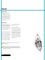
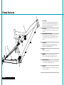
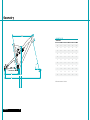
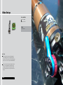
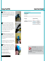
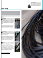
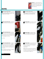
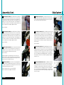
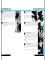
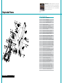
2011 575 OWNER’S MANUAL
YETI CYCLES
600 CORPORATE CIRCLE, UNIT D
GOLDEN, CO 80401
888.576.9384
USA
Table of Contents
Brand Overview
6
Frame Features
8
Geometry
10
Maintenance Schedule
12
Bike Setup Overview
14
ūū Shock Setup FOX RP23
16
ūū Quick Start Guide
17
ūū Cable Routing
18
Assembly Overview
20
ūū Assembly
22
ūū Chip System
25
ūū Disassembly Tips
27
Exploded Views
28
Part List
30
Warranty
32
Contact Information
33
Overview
Welcome to the tribe
Congratulations on your purchase of a new
Yeti bicycle and welcome to the Yeti Tribe. We
are confident your new bicycle will exceed your
expectations for value, performance and ride quality.
Each frameset and component has been custom
specified and designed to enhance your riding
experience. Whether you are a beginner cyclist or
a seasoned-pro, Yeti bicycles will provide endless
hours of two-wheeled fun.
General information
This model-specific manual is designed to be
used in conjunction with the general Yeti Owner’s
Manual and the manuals supplied by the suspension
manufacturers. If you did not receive the Yeti
Owner’s Manual or the manual provided by the
suspension manufacturer, download the materials
off the Internet, or contact you dealer.
Bicycling can be a hazardous activity even under
the best of circumstances. Proper maintenance of
your bicycle is your responsibility and when done
properly helps reduce the risk of injury and damage
to your bicycle. This manual outlines basic setup
and maintenance recommendations of your new
Yeti. Because it is impossible to anticipate every
situation or condition that may occur during the
assembly, setup and maintenance of your bicycle,
Yeti recommends that all service and repairs be
performed by an authorized Yeti dealer.
This manual contains many “Warnings” and
“Cautions” concerning the consequences of failure
to maintain or inspect your bicycle. The combination
of the safety alert symbol and the word “Warning”
indicates a potentially hazardous situation in which,
if not avoided, could result in serious injury or death.
The combination of the safety alert symbol and the
word “Caution” indicates a potentially hazardous
situation in which, if not avoided, may result in minor
injuries or damage to your bicycle or a component
of your bicycle. Be sure to read and understand all
“Warnings” and “Cautions”.
Warning: Make sure you review and understand the warnings, instructions and content of this manual and
accompanying manuals for your bicycle.
Warning: Technological advances have made bicycles and bicycle components more complex and the pace of
innovation is increasing. It is impossible for this manual or accompanying manuals to provide all the information
required to properly repair and maintain your bicycle. In order to help minimize the changes of injury, it is critical for you
to have work performed by an authorized Yeti dealer.
Overview
6
Frame Features
7
1.
Pure tubing
Yeti pure tubing is custom butted and tapered 7005 aluminum.
This makes the frame lightweight and strong without the use of
gussets. Unique shape perfectly compliments the shape of the
headtube for increased front-end stiffness.
1
2.
iscg 05’ tabs
Set up and run a 1x10 drivetrain with a chainguide cleanly and
effieciently.
3.
Re-designed chainstay and yoke provides a significant increase
in torsional rigidity. Internal cable routing through the chainstay
maximizes clearance between the chainstay, rear tire, and
crankset.
6
4.
4
hydroformed rear triangle
CarbonFlex pivots allowed us to shave weight and increases
performance. I-Beam construction has great lateral stiffness
and enhances suspension performance.
5
3
Flex pivots
5.
Shock
7.875” eye-to-eye / 2” stroke.
8
6.
Dogbone
Dogbone controls suspension rate and enhances rear end
stiffness. Sealed bearings allow the dogbone to move freely.
7.
Tapered headtube
The new tapered headtube provides an increase in torsional and
lateral stability with a negligible weight penalty.
2
Features
8
8.
Main pivot
Oversized sealed bearings on main pivot for low maintenance and
stiction-free performance.
Geometry
B
I
G e o met r y 575
150 mm fork
A
J
D
C
K
E
G
H
XS
S
M
L
XL
A
16.0
17.5
18.5
20.5
20.5
B
21.8
22.8
23.8
24.8
25.6
C
68.0
68.0
68.0
68.0
68.0
D
72.8
72.8
72.8
72.8
72.8
E
16.9
16.9
16.9
16.9
16.9
F
42.4
43.5
44.5
45.6
46.4
G
13.3
13.3
13.3
13.3
13.3
H
28.8
29.3
29.3
29.3
29.3
I
3.60
4.50
4.50
5.10
5.10
j
20.5
20.5
20.5
20.5
20.5
k
1.55
1.55
1.55
1.55
1.55
F
*All measurements are in inches.
Geometry
10
Maintenance? Not sure how to work on your own bike?
Contact your authorized Yeti dealer or visit www.parktool.com
and check out the repair help section. This section contains
detailed instruction on many of the service items listed in the
maintenance schedule.
Maintenance
Maintenance Following these guidelines will help maintain the performance of your bicycle and prevent
Torque We have attached a brief list of torque specifications for bolts and components that may need to
more serious problems from arising. It is important to remember that service intervals can vary depending
on climate, trail conditions and riding frequency.
be tightened while performing basic maintenance. This is just a guide. For specific torque, specifications,
please contact the component manufacturer directly.
ACTION
WEEKLY
Clean and lube chain
x
Check tire pressure
x
MONTHLY
3 MONTHS
ANNUALLY
Pivot Bolts
Derailleur Hanger Bolts
x
Clean bike of mud and debris (never
spray water directly into frame or
components)
Torque Specs
150 -180
Stem Binder Bolt
175 -260
150 -180
175 -250
Check brake function
x
Check shock pressure, if applicable
x
Saddle Clamp Bolts
Check for loose bolts and tighten, if
necessary
x
x
Thoroughly clean pivot points with a
rag (do not lubricate)
x
Replace brake pads, if necessary
x
Check tires for wear
x
Check spoke tension and retention, if
necessary
x
Check chain for worn, damaged, or
loose links, replace chain if necessary
x
Maintenance
12
Rear Derailleur
70 -86
Front Derailleur Clamp
45 -60
Chainring Bolts
88 -132
Caution: The torque specifications listed should be used as a guide when performing maintenance. Technological
advances have made bicycles and bicycle components more complex, and the pace of innovation is increasing.
Because of these advances, Yeti recommends that you refer to the torque specifications of the manufacture’s component
you are adjusting. In order to help minimize the chances of injury, do not perform any maintenance that you are not
confident can be completed within your abilities.
x
Complete tune-up performed by an
authorized Yeti dealer
30 -45
Handlebar Binder Bolt
Seatpost Binder Bolt
Check headset and tighten / loosen, if
necessary
125 -150
Bike Setup
Tools needed
Shock pump
Tape measure
Time
15-20 minutes
Yeti Tips
Inspect your shock for any visible damage. If
oil is leaking or you notice any damage to the
surfaces or seals, please contact the Fox Racing
Shox service center for repair at 800.FOX.SHOX.
Shock set-up can fluctuate greatly based on the
rider. The set-up guide is intended as a base
line to get the rider started. Experiment with
your settings to find the set-up that works best
for you.
SETUP
14
Quick Start Guide
Setup-Fox RP23
Air pressure The main air spring controls the sag of the shock.
For the 575 to ride properly it is important to setup the shock with the
correct amount of sag. For general riding use 20-30% of the shock stroke
(5mm to 10mm). To increase sag reduce the main spring air pressure. To
reduce sag increase the main spring air pressure. Refer to the quick start
guide to get your starting air pressure.
1
Quick start guide rp23 575
Air Spring Settings
Rider Weight (lbs)
125
135
145
155
165
175
185
195
205
215
Air Pressure (psi)
145
155
165
180
190
200
215
225
235
245
Sag Settings
2 sag Once you have set your baseline air pressure you need to
measure the sag. To measure the sag slide the travel indicator
(O-Ring) up against the shock body. With a friend supporting the bike, sit
on the saddle (do not bounce) and allow your body weight to compress
the shock. Once you have compressed the shock, get off the bike and
measure the distance between the shock body and the new position of the
travel indicator (O-Ring). This is your sag. Refer to the guide below for the
percentage of sag equivalents for the measurement recorded.
*External Adjustments
Sag %
20
25
30
Rebound
5 Clicks
Measured (mm)
10
12.5
15
Pro-Pedal Lever
On//Active
Pro-Pedal Knob
Position 2
Firm ride- 20-25% sag // Plush ride- 30% sag
Pro-Pedal The pro-pedal dampening has two settings and three
levels of adjustment and is controlled by the blue lever (formerly
the lock-out lever). The two settings are open and propedal. Use each
setting to adjust the shock for different riding conditions and situations. For
example use propedal for riding to the top of the mountain and then switch
to open for the descent.
3
The pro pedal knob has three different levels of dampening: (1) light, (2)
medium and (3) heavy pro-pedal. If the bike feels too firm, put it on a light
setting, and if it feels too sluggish, turn it to the stiffer setting.
rebound The rebound adjustment has 8-10 clicks of adjustment.
The rebound knob is the red adjustment dial located above your blue
pro-pedal adjustment lever. As a general rule, adjustments that are too fast
(counter-clockwise adjustment) will produce a springy ride with excessive
kick-up of the rear end causing a bucking sensation. Adjustments that
are too slow (clockwise adjustment) will cause packing of the rear wheel
indicated by a sluggish ride feeling ride.
4
Slower rebound- turn the knob clockwise
Faster rebound- turn the knob counter-clockwise
SETUP shock RP23
16
What is Pro-Pedal? Pro-pedal is a compression tune that
gives the right amount of low-speed compression to filter out
unwanted rider-induced bob without sacrificing critical midand high-speed damping. No flushing through your travel,
no wasted setup time, and no energy-sucking suspension
movement. Just super efficient pedaling performance ready
for hits of any size.
Bolt-on Cable guides 2011 Yeti frames use bolt-on cable
guides for routing brake and shift housing. The guides allow
for clean cable routing and thier two-piece design keeps the
housing from contacting the frame and marring the finish.
Cable Setup
The 575 has full cable housing. By using full cable housing, we have eliminated break points in the line
of your shifter housing. This allows riders to experience better overall shifting performance by reducing
the entrance of unwanted elements such as sweat and sediment. Use of full cable housing helps prevent
corrosion from the elements and keeps the shifting smoother for a longer period of time.
Caution: The failure to properly route shifter housing can cause malfunction of the shift mechanism and unexpected
shifting of gears.
REAR DERAILLEUR Fit the housing from the rear shifter across the
head tube and down the cable stops. There are three cable stops
groups on the bottom of the down tube to which the housing and brake line
can be attached, each with three positions to secure housing. Fit the rear
housing line along the down tube through these stops using the middle
position.
1
Next route the housing over the bottom bracket and into the drive side
chainstay. Be sure to run the housing through the guide on the front
derailleur mounting plate before inserting it into the chainstay. Push the
housing through the chainstay and loop into the rear derailleur to finish.
front derailleur Fit a piece of housing from the front shifter
across the head tube and into the cable stops on the down tube. Run
the housing line along the down tube though the three cable stops, using
the position closest to the drive side.
2
Next route the housing under the bottom bracket and into the stop under
the chainstay yoke. Ensure the housing loops into the chainstay stop to
allow enough slack when the suspension is compressed. Run the wire
cable through the housing and attached to the derailleur to finish.
rear brake The rear brake line loops across the head tube and into
the bolt-on cable stops on the down tube. Use the position closest to
the non-drive side on the cable guides for the rear brake line.
3
Next route the brake line over the bottom bracket shell and across the
non drive chainstay. Secure the line to the two single cable guides on the
chainstay with cable clips or zip ties. Ensure the line is finished on the
inside of the seatstay when attached to the caliper body. This will prevent
the brake line from being compromised if the bike or rider falls.
SETUP HOUSING
18
Assembly
Tools needed
Dead Blow Hammer
Two-5mm allen keys
6mm allen key
4mm allen key
3mm allen key
Fox guide pin tool
Time
30-45 minutes depending
on condition of the bike
Yeti Tips
Make sure your tools are in good condition.
A worn allen key can round the head of bolt
preventing proper torque. Be careful when using
ballend allen wrenches for the same reason.
Not every tool may be needed for the assembly /
disassembly of your bike. The list encompasses
all the tools necessary to completely assemble
and disassemble a each bike.
Torque settings are listed throughout the
instructions. It is also important to prep all bolt
threads. The instructions denote whether to use
a blue Loctite compound or grease.
Warning: Service on Yeti bicycles requires special
knowledge and tools. Yeti Cycles recommends that all
service and repairs be performed by an authorized Yeti
dealer.
assembly
20
Thread Prep Yeti recommends prepping all bolt threads
at once on your work bench with Loctite or grease. This will
ensure that all bolts are used in assembly. The medium
strength (blue) Loctite formula along with proper torque is
ideal to keep the bolts snug.
Assembly
DOGBONE AND SHOCK MOUNTING ASSEMBLY Install two M4x10mm
bolts into the bottom of the dogbone. Prep the threads with locktite
and torque the bolts tight enough to hold the bearings in place. The bolts
will be torqued to spec later in the assembly.
1
2
Dogbone & shock mounting assembly Use a dead blow hammer
to install two 15mm reducers into the lower portion of the shock.
DOGBONE AND SHOCK MOUNTING ASSEMBLY Align the shock and
dogbone. Orient the lower portion of the shock between the lower
bearings on the dogbone. If necessary, loosen the pinch bolts on the
dogbone to allow the bearings to move and accommodate the shock.
5
6
Rear Triangle Assembly Slide the swingarm over the main pivot
bore, using the grooves in the swingarm to properly align over the
bore.
Dogbone & shock mounting assembly Install the shock and
dogbone on the frame. Insert a 31.0 mm Ti female bolt through the
drive side of the frame for the shock. Use a Ti male bolt on the non-drive
to tighten the shock into place with a 5mm allen key. Support the bottom of
the shock while tightening the shock to the frame.
3
Mounting rear triangle Use the fox guide pin to align and
hold the seatstays, dogbone, and shock together. Use a dead blow
hammer to push the pin through the above mentioned components.
7
Torque: 90-95 in-LB
Dogbone & shock mounting assembly Install the dogbone using
a 40.5mm Ti female bolt and a Ti male bolt. Orient the dogbone so
the Yeti logo is facing the rear of the frame, and use a dead blow hammer to
insert 40.5mm female bolt through the top of the dogbone and the frame.
Use the Ti male bolt on the non-drive side to tighten the dogbone into place
with a 5mm allen key.
4
Tip: Use the fox guide pin tool and a dead blow hammer to help guide any
female Ti bolts through frames and frame components.
assembly
22
Mounting rear triangle Install the main pivot pin (female) from
the drive side of the bike. Use a dead blow hammer to push the pin
into place. Once the female pivot pin is in place, install and tighten the
male pivot bolt with a 5mm allen key.
Torque:115-125 in/LBs
8
Tip: While installing the female main pivot pin, align the swingarm with the
main pivot bore in the front triangle with your free index finger. Use grease
on the threads of the male bolt and on the outside of the female pin. This
will help prevent binding, seizing, or stripping over time.
Assembly Cont.
Mounting rear triangle Prep an M6x1x12mm male Ti bolt with
locktite and install into the 57.5 mm Ti stud. Place the 57.5 Ti stud
and Ti male bolt assembly over the male portion of the Fox guide pin. Use
a dead blow hammer to push the bolt into place. Be prepared to catch the
guide pin as it exits the non-drive side of the bike. Install and tighten a Timale bolt to the non drive side of the 57.5mm Ti stud with a 5mm allen key.
Check the alignment of the swingarm, dogbone, and shock.
9
Chip System
Removing stock chip set Use a 2.5mm allen key to loosen the
two M4x9mm flat head bolts holding the QR insert derailleur hanger
in place. Remove the bolts and the QR insert from the frame. Repeat the
process for the bolts and the non drive QR insert.
1
Torque: 90-95 in/lbs
Mounting rear triangle Prep an M6x1x12mm male Ti bolt with
locktite and install into the 57.5 mm Ti stud. Place the 57.5 Ti stud
and Ti male bolt assembly over the male portion of the Fox guide pin. Use
a dead blow hammer to push the bolt into place. Be prepared to catch the
guide pin as it exits the non-drive side of the bike. Install and tighten a Timale bolt to the non drive side of the 57.5mm Ti stud with a 5mm allen key.
Check the alignment of the swingarm, dogbone, and shock.
10
Installing dt dropout kit Fit the 12MM insert derailleur hanger
into the groove on the inside of the drive side chainstay. The hanger
should be flush with the chainstay. Next, insert the threaded 12mm cap
through the chainstay and into the hanger from the outside of the drive side
chainstay. To finish, use a 3MM allen key to attach the two dropout pieces
to the swingarm with two M4x15MM cap bolts. Prep the bolts with locktite
and insert them into the threaded cap, through the swingarm and into the
derailleur hanger.
2
Torque: 90-95 in/lbs
Torque: 15-20 in/lb
Front Derrailleur Mount Insert the front derailleur mount into
the main pivot area of the front triangle. Orient the mount so the
cable guide is closest to the back of the frame. Fasten the mount to the
frame using a 16.5mm Ti female bolt and a Ti male bolt.
Torque: 90-95 in-lb
11
Tip: When installing an e-type front derailleur to the mount, use the
provided cover plate, spacer, and custom bolts to fasten the derailleur.
The spacer can be rotated in two positions to allow the proper clearance
between the derailleur and largest chain ring.
COMPLETE ASSEMBLY Ensure that there is equal spacing between
the bearings in the dogbone and the bearings in the seatstays on the
rear triangle. The shoulders of the two bearings on each side of the frame
should be pushed flush against one another.
10
Torque the pinch bolts on the seatstays to 40-45 in/LB.
Torque the pinch bolts on the dogbone to 25-30 in/LB.
assembly
24
installing dt dropout kit Fit the 12MM non-drive insert into
the groove on the inside of the non-drive side chainstay. The insert
should be flush with the chainstay. Next, insert the un-threaded 12mm cap
through the chainstay and into the insert from the outside of the non-drive
side chainstay. To finish, use a 3MM allen key to attach the two dropout
pieces to the swingarm with two M4x15MM cap bolts. Prep the bolts with
locktite and insert them into the un-threaded cap, through the swingarm
and into the insert.
3
Installing Shimano dropout kit Fit the 12MM insert derailleur
hanger into the groove on the inside of the drive side chainstay. The
hanger should be flush with the chainstay. Next, insert the 12mm drive
cap through the chainstay and into the hanger from the outside of the drive
side chainstay. To finish, use a 3MM allen key to attach the two dropout
pieces to the swingarm with two M4x15MM cap bolts. Prep the bolts with
locktite and insert them into the drive cap, through the swingarm and into
the derailleur hanger.
4
Chip System Cont.
Dissassembly Tips
installing shimano dropout kit Fit the 12MM non-drive insert
into the groove on the inside of the non-drive side chainstay. The
insert should be flush with the chainstay. Next, fit the non-drive 12mm cap
through the chainstay and into the insert from the outside of the non-drive
side chainstay. To finish, use a 2.5MM allen key to attach the two dropout
pieces to the swingarm with two M4x10MM flat head bolts. Prep the bolts
with locktite and insert them into the non-drive cap, through the swingarm
and into the insert.
Torque: 15-20 in/lb
REAR TRIANGLE DISASSEMBLY
Loosen the pinch bolts at the top of
the seatstays.
Installing shimano dropout kit Insert the M4x6MM custom
cap bolt into the top of the drive cap. This bolt will be used to set the
position of the Shimano 142x12MM axle. Refer to Shimano literature for
exact instructions on axle operations.
REAR TRIANGLE DISASSEMBLY Insert the guide pin tool into the non
drive side of the 57.5 mm Ti stud and use a dead blow hammer to tap
the stud out of the frame. Be prepared to catch the stud as it exits the drive
side of the frame. Leave the guide pin in the frame during the next step.
5
6
1
At the seatstay junction, remove the Ti
male bolt on the non-drive side of the
frame from the 57.5 Ti stud with a 5mm
allen key.
2
Torque: 15-20 in/lb
REAR TRIANGLE DISASSEMBLY Remove the male main pivot bolt
from the female main pivot pin with a 5mm allen key. Use a punch
and a dead blow hammer to remove the main pivot pin from the swingarm
and front triangle. Tip: Brace the front triangle of the frame with your body
while removing the main pivot pin. This will help prevent any damage to the
front triangle and swingarm, and will allow for easier removal of the pin.
3
Tip: Use an adequate sized punch to prevent damage to the threads in the
main pivot pin.
SHOCK & DOGBONE DISSASSEMBLY Remove the guide pin from the
seatstay junction and then pull the rear triangle off of the frame.
Remove the male bolt from the 40.5mm Ti female bolt holding the dogbone
in place. Use the guide pin and a dead blow hammer to tap the female bolt
out of the frame.
4
Repeat the process for the bolts holding the shock in place.
chip system
26
disassembly
27
Rebuild Kits The individual components of each Yeti bike
are not sold separately. All Yeti parts are sold in rebuild kits
listed below. Each and every part can be obtained by purchasing one of the rebuild kits. Cross reference the part number
you desire from the parts lists.
Exploded Views
Parts list w/fox shock
Qty.
11
5
4
5
12
3
11
6
18
12
18
11
21
12
18
31
31
13 16
32
18
12
2
6
32
19
18 14
13 11
9
23
24 25
11
10 9
30
30
4
22 18
22
7
20
19 21 20
1
13 17
31
27
32
26
8
28 29
exploded views
30
30
28
13
15
Part #
Description
1
1
NA
Front Triangle
2
1
NA
575 Swingarm (Color Specific)
3
1
NA
Fox Rear Shock - RP23
4
2
300020020
Fox Garlock
5
2
300020034
Reducer - 22mm (Front)
6
2
300020035
Reducer - 8mm x 7.5mm (Rear)
7
1
300040235
575 Dogbone
8
1
300030188
Pivot Pin (M10 x 17 x 52.4mm)
9
2
300020001
Bearing 3903 2RS Double Row
10
1
300030189
Pivot Pin (M10 x 1 x 22mm)
11
5
300030110
Bolt - Ti - Male (M6 x 1 x 12mm)
12
4
300030069
Washer (8.5 x 12.5 x 0.5mm)
13
4
300030062
Washer (6.5 x 12.5 x 0.5mm)
14
1
300030191
Stud - Ti - Female (M6 x 8 x 57.5mm)
15
1
300030190
Bolt - Ti - Female (M6 x 8 x 40.5mm)
16
1
300030186
Bolt - Ti - Female (M6 x 8 x 31mm)
17
1
300030114
Bolt - Ti - Female (M6 x 8 x 16.5mm)
18
6
300020032
Bearing 398 2RS MAX Double Row
19
2
300040349
Barrel Insert (M5)
20
2
300030010
Bolt - Cap H20 (M5 x 0.8 x 16mm)
21
2
300030124
Washer 5.5mm ID x 9mm OD
22
2
300030194
Bolt Cap Sckt M4 x 10mm
23
1
100130038
ASR - 7 Front Derrailleur Mount
24
1
300030138
ASR - 7 Derrailleur Spacer E-Type
25
1
100130040
FD E-Type Cover Plate
26
1
300030140
Custom Bolt (M5 x 12mm)
27
1
300030141
Custome Bolt (M5 x 18mm)
28
1
300040386
QR Insert Non - Drive
29
1
300060061
QR Insert Derrailleur hanger
30
4
300030221
Bolt Flat Head (M4 x .7 x 9mm)
31
3
300030139
Bolt Flat Head (M4 x .7 x 16mm)
32
3
300040398
Bolt-On Cable Guide Triple Set
Parts List
PART NUMBER
200020184
200020185
200020136
200020162
parts List
DESCRIPTION
Qty.
1
575 2011 bearing rebuild kit
300020032
bearing 398 rs max dbl row 19mm x 8mm x 11mm
6
300020030
bearing 3903 2rs double row
2
1
575 2011 master rebuild kit
300030191
stud ti female 8 x 57.5mm
1
300030190
bolt ti female 8 x 40.5mm m6x1
1
300030186
bolt ti female 8 x 31.0mm m6x1
1
300030062
washer ss 6.5mm id 12.5 od .5m
3
300030069
washer ss 8.5mm id 12.5mm od
3
300030110
bolt ti male m6x1 12mm m6x1
3
300030188
Pivot Pin M10 x 17 x 52.4mm
1
300030189
pivot pin bolt M10 x 1 x22
1
300020035
reducer 8mm x 7.5 mm rear
2
300020034
reducer 22mm front
2
300020032
bearing 398 rs max dbl row 19mm x 8mm x 11mm
6
300020030
bearing 3903 2rs double row
2
1
575 ‘08-’11 pinch bolts for swingarm / dogbone
300030194
bolt cap sckt hd m4 x .7 x 10 stainless
2
300040349
barrel insert m5 rolled threads w/ position
2
300030011
bolt cap m5 x .8 x 12 stainless
2
575 2011 front Derrailleur mount kit
300030141
custom bolt M5 x 18mm
1
300030140
custom bolt m5 x 12mm
1
300030138
asr-7 derrAilleur spacer e-type
1
300030114
bolt ti female 8x16.5mm
1
300030110
bolt ti male m6x1 12mm m6x1
1
300030069
washer ss 8.5mm id 12.5mm od
1
300030062
washer ss 6.5mm id 12.5 od .5m
1
100130040
front derrailleur e-type cover
1
100130038
asr-7 front derrrailleur mount
1
30
Warranty
Yeti Limited (2) Two Year Frame Warranty (applies to 303 DH, 303 RDH, 25TH 303 DH, AS-R 7 > 160MM
Fork, DH-9, AS-X, 4X, DJ, SX)
Yeti Cycles will repair or replace, at its option, any frame it determines to be defective materials and / or
workmanship. The (2) two year limited warranty is conditioned upon the bicycle being ridden under normal
conditions and having been properly maintained. This warranty does not apply to the components attached
to the frameset such as suspension components, wheels, drive train, brakes, seatpost, handlebar and stem.
This warranty applies only to the original owner and is non-transferable. This warranty is void if the bicycle
was not properly assembled by an authorized Yeti dealer.
Yeti Limited (5) Five Year Frame Warranty (applies to AS-R 5 Carbon, AS-R 5 Alloy, AS-R Carbon, AS-R
Alloy, AS-R-sl(c), AS-R, AS-R 7 w/160MM Fork, 575, ARC, ARC-X, Big Top 29’R, FRO, Kokopelli)
Yeti Cycles will repair or replace, at its option, any frame it determines to be defective materials and / or
workmanship. The (5) five year limited warranty is conditioned upon the bicycle being ridden under normal
conditions and having been properly maintained. This warranty does not apply to the components attached
to the frameset such as suspension components, wheels, drive train, brakes, seatpost, handlebar and stem.
This warranty applies only to the original owner and is non-transferable. This warranty is void if the bicycle
was not properly assembled by an authorized Yeti dealer.
Additional Conditions
These limited warranties do not apply to normal wear and tear, nor to claimed defects, malfunction or
failures that result from abuse, neglect, improper assembly, improper maintenance, alteration, collision,
crash or misuse. The original owner shall pay all labor charges connected with the repair or removal of all
components. Under no circumstances does this limited warranty include of the cost of travel or shipment to
and from an authorized Yeti dealer. In order to exercise your rights under these limited warranties, the bicycle
or frameset must be presented to an authorized Yeti dealer, together with proof of purchase.
ūū The above warranties have been in effect since January 2000. All Yeti frames sold prior to that date
had a limited (1) one year warranty on the frameset.
ūū No Fault Replacement Policy
ūū Yeti Cycles will make replacement parts available at a minimum charge to the original owner in the
event of a crash or any other non-warranty situation. Yeti Cycles does this at its sole discretion and
reserves the right to refuse this offer.
ūū If you have a warranty concern, please contact your authorized Yeti dealer.
No Fault Replacement Policy
Yeti Cycles will make replacement parts available at a minimum charge to the original owner in the event of a
crash or any other non-warranty situation. Yeti Cycles does this at its sole discretion and reserve the right to
refuse this offer. If you have a warranty concern, please contact you authorized Yeti dealer.
Product Life Cycle
Every Yeti frameset has a useful product life cycle. The length of that useful product life cycle will vary
depending on the construction and materials of the frameset, maintenance and care the frameset receives,
and the amount and type of use the frameset is subjected to over its life. Yeti recommends that an authorized
Yeti dealer should inspect the frame for stress annually. Frame stress could cause potential failure and the
signs are usually apparent in the form of cracks, fracture lines, deformation, dents and other visual indicators
of abnormality. These safety checks for frame stress are important to prevent accidents, injury to the cyclist
Warranty
32
and product failure of a Yeti frameset.
Disclaimer
Yeti Cycles is not responsible for any damages to you or others arising from riding, transporting or other
use of your bicycle. In the event that your frame breaks or malfunctions, Yeti Cycles shall have no liability or
obligation beyond the repair or replacement of your frame pursuant to the terms outline in this warranty.
Contact info
Yeti Cycles
600 Corporate Circle, Unit D
Golden, CO 80401
(p) 303-278-6909
(f) 303-278-6906
www.yeticycles.com
BUSINESS HOURS
Monday-Friday
8AM-11:30AM, 1:00PM-5:30PM
(Mountain Time)