1
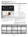
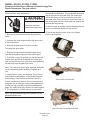
Service Manual for Remote Low Side Modular
Flaked and Nugget Ice Machines
including Prodigy Plus D Series Models
F1222L, F1322L, N0922L and N1322L
N0922L, N1322L, F1222L, F1522L
Remote Low Side Service Manual Includes Prodigy Plus
Introduction
This ice machine is the result of years of experience
with flaked and nugget ice machines. The latest in
electronics has been coupled with the time tested
Scotsman flaked ice system to provide reliable ice
making and the features needed by customers.
The features include simple conductivity water level
sensing, evaporator clearing at shut down, photo-eye
sensing bin control and the ability to add options.
Contents
Installation: . . . . . . . . . . . . . . . . . . . . . . . . . . . . . . . . . . . . . . . . . . . . . . . . . . . . . . . . . . . . . . . . . . . . . . Page 3
Location: . . . . . . . . . . . . . . . . . . . . . . . . . . . . . . . . . . . . . . . . . . . . . . . . . . . . . . . . . . . . . . . . . . . . . . . . Page 4
Cabinet Layout . . . . . . . . . . . . . . . . . . . . . . . . . . . . . . . . . . . . . . . . . . . . . . . . . . . . . . . . . . . . . . . . . . . Page 5
Unpacking. . . . . . . . . . . . . . . . . . . . . . . . . . . . . . . . . . . . . . . . . . . . . . . . . . . . . . . . . . . . . . . . . . . . . . . Page 6
Water. . . . . . . . . . . . . . . . . . . . . . . . . . . . . . . . . . . . . . . . . . . . . . . . . . . . . . . . . . . . . . . . . . . . . . . . . . . Page 7
Electrical . . . . . . . . . . . . . . . . . . . . . . . . . . . . . . . . . . . . . . . . . . . . . . . . . . . . . . . . . . . . . . . . . . . . . . . . Page 8
Refrigeration . . . . . . . . . . . . . . . . . . . . . . . . . . . . . . . . . . . . . . . . . . . . . . . . . . . . . . . . . . . . . . . . . . . . . Page 9
Final Check List. . . . . . . . . . . . . . . . . . . . . . . . . . . . . . . . . . . . . . . . . . . . . . . . . . . . . . . . . . . . . . . . . . . Page 10
Initial Start Up . . . . . . . . . . . . . . . . . . . . . . . . . . . . . . . . . . . . . . . . . . . . . . . . . . . . . . . . . . . . . . . . . . . . Page 11
Controller. . . . . . . . . . . . . . . . . . . . . . . . . . . . . . . . . . . . . . . . . . . . . . . . . . . . . . . . . . . . . . . . . . . . . . . . Page 12
AutoAlert and Display Code . . . . . . . . . . . . . . . . . . . . . . . . . . . . . . . . . . . . . . . . . . . . . . . . . . . . . . . . . Page 13
Component Indicator Lights. . . . . . . . . . . . . . . . . . . . . . . . . . . . . . . . . . . . . . . . . . . . . . . . . . . . . . . . . Page 14
Electrical Component Details . . . . . . . . . . . . . . . . . . . . . . . . . . . . . . . . . . . . . . . . . . . . . . . . . . . . . . . . Page 15
Sequence of Operation. . . . . . . . . . . . . . . . . . . . . . . . . . . . . . . . . . . . . . . . . . . . . . . . . . . . . . . . . . . . . Page 16
Electrical Sequence with Condensing Unit. . . . . . . . . . . . . . . . . . . . . . . . . . . . . . . . . . . . . . . . . . . . . . Page 17
Water System . . . . . . . . . . . . . . . . . . . . . . . . . . . . . . . . . . . . . . . . . . . . . . . . . . . . . . . . . . . . . . . . . . . . Page 18
Remote Refrigeration with Condensing Unit. . . . . . . . . . . . . . . . . . . . . . . . . . . . . . . . . . . . . . . . . . . . . Page 19
How Ice Is Made. . . . . . . . . . . . . . . . . . . . . . . . . . . . . . . . . . . . . . . . . . . . . . . . . . . . . . . . . . . . . . . . . . Page 20
Scale removal. . . . . . . . . . . . . . . . . . . . . . . . . . . . . . . . . . . . . . . . . . . . . . . . . . . . . . . . . . . . . . . . . . . . Page 21
Check Top Bearing . . . . . . . . . . . . . . . . . . . . . . . . . . . . . . . . . . . . . . . . . . . . . . . . . . . . . . . . . . . . . . . . Page 22
Bearing Service. . . . . . . . . . . . . . . . . . . . . . . . . . . . . . . . . . . . . . . . . . . . . . . . . . . . . . . . . . . . . . . . . . . Page 23
Options . . . . . . . . . . . . . . . . . . . . . . . . . . . . . . . . . . . . . . . . . . . . . . . . . . . . . . . . . . . . . . . . . . . . . . . . . Page 24
Service Diagnosis. . . . . . . . . . . . . . . . . . . . . . . . . . . . . . . . . . . . . . . . . . . . . . . . . . . . . . . . . . . . . . . . . Page 25
Service Diagnosis - Optional Ice Level Controls. . . . . . . . . . . . . . . . . . . . . . . . . . . . . . . . . . . . . . . . . . Page 26
Repair Procedures: Bearing And Breaker. . . . . . . . . . . . . . . . . . . . . . . . . . . . . . . . . . . . . . . . . . . . . . . Page 27
Repair Procedures: The Auger . . . . . . . . . . . . . . . . . . . . . . . . . . . . . . . . . . . . . . . . . . . . . . . . . . . . . . . Page 28
Auger and Evaporator Inspection . . . . . . . . . . . . . . . . . . . . . . . . . . . . . . . . . . . . . . . . . . . . . . . . . . . . . Page 29
Repair Procedures: The Water Seal:. . . . . . . . . . . . . . . . . . . . . . . . . . . . . . . . . . . . . . . . . . . . . . . . . . . Page 30
Repair Procedures: Replace the Evaporator:. . . . . . . . . . . . . . . . . . . . . . . . . . . . . . . . . . . . . . . . . . . . Page 31
Repair Procedures: The gear reducer. . . . . . . . . . . . . . . . . . . . . . . . . . . . . . . . . . . . . . . . . . . . . . . . . . Page 32
Repair Procedures: Thermostatic Expansion Valve . . . . . . . . . . . . . . . . . . . . . . . . . . . . . . . . . . . . . . . Page 33
December 2014
Page 2
N0922L, N1322L, F1222L, F1522L
Remote Low Side Service Manual Includes Prodigy Plus
Installation:
This machine is designed to be used indoors, in a
controlled environment. Operation outside the limits
listed here will void the warranty.
Air temperature limits
Ice maker
Minimum
50oF.
Maximum
100oF.
Warranty Information
The warranty statement for this product is provided
separately from this manual. Refer to it for applicable
coverage. In general warranty covers defects
in material or workmanship. It does not cover
maintenance, corrections to installations, or situations
when the machine is operated in circumstances that
exceed the limitations printed above.
Water temperature limits
All models
Minimum
40oF.
Maximum
100oF.
Water pressure limits (potable)
All models
Minimum
20 psi
Maximum
80 psi
Minimum
104
Maximum
126
Most water filters remove chlorine from the water
supply to the machine which contributes to this
situation. Testing has shown that using a filter that
does not remove chlorine, such as the Scotsman
Aqua Patrol, will greatly improve this situation.
Voltage limits
115 volt
Minimum conductivity (RO water)
• 10 microSiemens / CM
Water Quality (ice making circuit)
• Potable
The quality of the water supplied to the ice machine
will have an impact on the time between cleanings
and ultimately on the life of the product. Water can
contain impurities either in suspension or in solution.
Suspended solids can be filtered out. In solution
or dissolved solids cannot be filtered, they must be
diluted or treated. Water filters are recommended
to remove suspended solids. Some filters have
treatment in them for suspended solids. Check with a
water treatment service for a recommendation.
RO water. This machine can be supplied with Reverse
Osmosis water, but the water conductivity must be no
less than 10 microSiemens/cm.
Potential for Airborne Contamination
Installing an ice machine near a source of yeast
or similar material can result in the need for more
frequent sanitation cleanings due to the tendency of
these materials to contaminate the machine.
December 2014
Page 3
N0922L, N1322L, F1222L, F1522L
Remote Low Side Service Manual Includes Prodigy Plus
Location:
While the machine will operate satisfactorily within the
air and water temperature limits, it will operate more
efficiently when those temperatures are nearer the
lower limits. Avoid locations that are hot, dusty, greasy
or confined.
Options
The standard machine will make ice until ice fills
the bin and blocks an infrared light beam inside the
bottom of the machine. A field installed kit is available
to adjust the ice level lower. That kit number is KVS.
The standard controller has excellent diagnostic
capabilities and communicates to the user through the
AutoAlert light panel, seen through the front panel.
There is a field installed kit that can log data and
provide additional information when the front panel is
removed. That kit number is KSBU. A similar kit adds
network connectivity, and its number is KSB-NU.
Bin compatibility
All models are the same width: 22 inches. All models
are the same depth: 24 inches.
Dispenser compatibility
Only nugget ice models may be used with ice
dispensers. Flaked ice is not dispensable.
• ID150 – use KBT42 and KDIL-PN-150; includes
KVS, KNUGDIV and R629088514
• ID200 – use KBT43 and KNUGDIV and KVS
• ID250 – use KBT43 and KNUGDIV and KVS
See sales literature for other brand model ice and
beverage dispenser applications.
Other Bins & Applications:
Note the drop zone and ultrasonic sensor locations in
the illustrations on the next page.
Line Set
NRTE45 is a non-precharged tubing kit that contains
a 45 foot 3/8" liquid line and a 45 foot 5/8" suction
line. Tubes are supplied nitrogen charged and
capped.
Scotsman ice systems are designed and
manufactured with the highest regard for safety and
performance.
Bin & adapter list:
• B322S – no adapter needed
• B330P – Use KBT27
Scotsman assumes no liability of responsibility of
any kind for products manufactured by Scotsman
that have been altered in any way, including the use
of any part and/or other components not specifically
approved by Scotsman.
• B530P – Use KBT27
• B530S – Use KBT27
• B842S – Use KBT39
• B948S - Use KBT38 for a single unit
• B948S – Use KBT38-2X for two units side by side
Scotsman reserves the right to make design changes
and/or improvements at any time. Specifications and
design are subject to change without notice.
BH1100, BH1300 and BH1600 upright bins include
filler panels to accommodate a single 22 inch wide
flake or nugget ice machine. No adapter is needed.
December 2014
Page 4
N0922L, N1322L, F1222L, F1522L
Remote Low Side Service Manual Includes Prodigy Plus
Cabinet Layout
55.4
21.81
33.9
13.35
3/8"FLARE
MACHINE
WATER INLET
47.8
18.81
6.7
2.63
4
1.59
42.8
16.86
36.5
14.36
3/4" FPT DRAIN
BACK VIEW
120 VOLT CORD
5/8" O.D. REMOTE
SUCTION
CONNECTION
3/8" O.D. REMOTE
LIQUID LINE
CONNECTION
61
24.00
REF.
41.9
16.50
55.9
22.00 REF.
PLAN VIEW
31.8
12.50
16.5
6.48
ICE DROP
OPENING
61
24.00
LEFT SIDE VIEW
10.9
4.30
7.4
2.92
ULTRA SONIC
BIN LEVEL
SENSOR
OPTIONAL
7.1
2.81
[68.6]
27.00
57.7
22.70
55.9
22.00
FRONT VIEW
December 2014
Page 5
N0922L, N1322L, F1222L, F1522L
Remote Low Side Service Manual Includes Prodigy Plus
Unpacking
Remove the carton from the skid. Check for hidden
freight damage, notify the carrier immediately if any is
found. Retain the carton for the carrier’s inspection.
Panel Removal
The machine is not bolted to the skid. If strapped
remove the strap.
Place on Bin or Dispenser
If reusing an existing bin, be sure that the bin is in
good shape and that the gasket tape on the top is not
torn up. Water leaks, not covered by warranty, could
result from a poor sealing surface. Because this is a
remote low side, a new bin is recommended due to
the high cost to the user of replacing an old bin when
a remote system is on top.
Install the correct adapter, following the directions
supplied with that adapter.
Hoist the machine onto the adapter.
Note: The machine is heavy! Use of a mechanical lift
is recommended.
Position the machine on the bin or adapter. Secure
with straps from the hardware bag packed with the
machine, or those supplied with the adapter.
Remove any plastic covering the stainless steel
panels.
Remove any packaging, such as tape or foam blocks,
that may be near the gear reducer or ice chute.
Level the bin and ice machine front to back and left to
right by using the bin leg levelers.
1. Locate and loosen the two screws at the bottom
edge of the front panel.
2. Pull the front panel out at the bottom until it clears
the bin.
3. Lower the front panel down and off the machine.
4. Remove two screws at the front of the top panel.
Lift up the front of the top panel, push the top panel
back an inch, then lift to remove.
5. Locate and loosen the screw holding each side
panel to the base. Left side panel also has a screw
holding it to the control box.
6. Pull the side panel forward to release it from the
back panel.
December 2014
Page 6
N0922L, N1322L, F1222L, F1522L
Remote Low Side Service Manual Includes Prodigy Plus
Water
The water supply for ice making must be cold, potable
water. There is a single 3/8” male flare potable water
connection on the back panel.
Backflow
The design of the float valve and reservoir prevents
potable water backflow by means of a 1" air gap
between the reservoir's maximum water level and the
float valve water inlet orifice.
Drain
There is one ¾” FPT condensate drain fitting at the
back of the cabinet.
Potable Water Inlet
Tubing
Connect the potable water
supply to the potable water
fitting, 3/8” OD copper tubing or
the equivalent is recommended.
Connect the drain tube to the
condensate drain fitting. Vent this
drain tube.
Do not Tee ice machine drains
into the drain tube from the ice
storage bin or dispenser. Back
ups could contaminate and
/ or melt the ice in the bin or
dispenser.
Follow all local and national
codes for tubing, traps and air
gaps.
Condensate Drain
December 2014
Page 7
N0922L, N1322L, F1222L, F1522L
Remote Low Side Service Manual Includes Prodigy Plus
Electrical
The machine includes a power cord, connect
to the proper power supply. A separate circuit is
recommended to avoid unintended shut downs.
If a dedicated condensing unit is connected to this
machine, it will have a separate power supply.
Do not use an extension cord.
Follow all local and national codes.
Model
Dimensions
Voltage
All
w" x d" x h"
22 x 24 x 27
Volts/Hz/Phase
115/60/1
Min Circuit Ampacity Max Fuse Size
(cord connected)
5.8
15
Power Cord
3/8 OD Liquid Line Stub
5/8 OD Suction
Line Stub
December 2014
Page 8
N0922L, N1322L, F1222L, F1522L
Remote Low Side Service Manual Includes Prodigy Plus
Refrigeration
BTUH Capacity Requirements
Model
N0922L, F1222L
N1322L, F1522L
Refrigeration Installation:
BTUH
5,000
7,200
Connections
Condensing Units
The liquid and suction fittings on the back of the
cabinet are stubs. The liquid line size is 3/8" OD. The
suction line size is 5/8" OD.
Model Use Condensing Unit
1. Recover holding charge
N0922L or F1222L
N1322L or F1522L
2. Cut the stubs off.
NME954-RHS-A/C
None - rack only
Remote low side models require connection to a
dedicated condensing unit or a rack system.
Recommended Tubing from Head to Condensing Unit
•
Suction Line: 5/8" OD
•
Liquid Line: 3/8" OD
3. Braze line set tubing to each fitting. Sweep with
dry nitrogen while brazing.
4. Dedicated condensing unit: Evacuate complete
system to 50 microns.
5. Open the ball valves.
Distance limits:
Rack: The skills of a refrigeration technician are
required to connect the ice machine to the building’s
refrigeration system.
•
Notes:
•
Maximum distance between dedicated condensing
unit and head: 75 feet.
Condensing Unit Elevation over Ice Making
Section: 35 feet.
Note: Elevations greater than 20 feet require
installation of a suction line trap at the 10 foot mark.
Ice Making Section
•
•
R-404A models: 1.5 ounces of R-404A refrigerant
is in the system as a holding charge.
•
Be sure the liquid connection is NOT in series with
another liquid line valve.
•
Local Codes must be observed.
Dedicated condensing unit: Add refrigerant charge.
Recommended starting field charge:
Elevation over Condensing Unit: 15 feet.
Line Routing:
•
N0922L or F1222L: 8 lb R-404A
•
Allowed: One rise after a drop.
•
N1322L of F1522L: n/a - rack only
•
Allowed: One drop after a rise.
•
Not Allowed: More than one rise after a drop
•
Not Allowed: More than one drop after a rise
Roof Attachment
Install and attach the remote condensing unit to the
roof of the building, using the methods and practices
of construction that conform to the local building
codes, including having a roofing contractor secure
the condenser to the roof.
December 2014
Page 9
N0922L, N1322L, F1222L, F1522L
Remote Low Side Service Manual Includes Prodigy Plus
Final Check List
After Connections
Control Operation
1. Wash out the bin. If desired, the interior of the bin
could be sanitized.
Use and Operation
2. Locate the ice scoop (if supplied) and have it
available for use when needed.
Final Check List:
1. Is the unit located indoors in a controlled
environment?
2. Is the unit located where it can receive adequate
cooling air?
3. Has the correct electrical power been supplied to
the machine?
4. Have all the water supply connections been
made?
Once started, the ice machine will automatically make
ice until the bin or dispenser is full of ice.
When ice level drops, the ice machine will resume
making ice.
Caution: Do not place anything on top of the ice
machine, including the ice scoop. Debris and moisture
from objects on top of the machine can work their way
into the cabinet and cause serious damage. Damage
caused by foreign material is not covered by warranty.
There are four indicator lights at the front of the
machine that provide information on the condition of
the machine.
Indicator Lights:
5. Have all the drain connections been made?
• Power
6. Has the unit been leveled?
• Status
7. Have all unpacking materials and tape been
removed?
• Water
8. Is the correct switch bezel installed in the trim
strip?
9. Is the water pressure adequate?
10.Have the drain connections been checked for
leaks?
11.Has the bin interior been wiped clean or sanitized?
12.Have any water filter cartridges been replaced?
Switch Door
• De-scale &
Sanitize
Prodigy Plus: Under the door are two switches –
On and Off. To switch the machine OFF, push and
release the Off button. The machine will shut off at the
end of the next cycle.
To switch the machine ON, push and release the
On button. The machine will go through a start up
process and then resume ice making.
13.Have all required kits and adapters been properly
installed?
14.Has the ice machine been properly connected to
the condensing unit or rack?
December 2014
Page 10
N0922L, N1322L, F1222L, F1522L
Remote Low Side Service Manual Includes Prodigy Plus
Initial Start Up
1. Turn the water supply on.
• All models require sensor cleaning.
2. Switch the electrical power on. Confirm voltage is
correct for the model.
• All models require a top bearing check.
3. Push and release the On button. The machine will
start up in about two minutes.
The liquid line valve will open and liquid refrigerant
will flow into the machine. For the units connected to
a dedicated condensing unit, the resulting increase in
suction pressure will start the condensing unit and the
condensing unit will begin discharging warm air from
the remote condenser. After about 5 minutes, ice will
begin to drop into the bin or dispenser.
4. Check the machine for unusual rattles.
5. Tighten any loose screws, be sure no wires are
rubbing moving parts. Check for tubes that rub.
6. Check suction pressure, adjust EPR setting. As
shipped the EPR valve should maintain low side
pressure at about 36 PSIG + or - 2 PSIG.
Note: Machines will operate and make ice at the
factory EPR setting. For optimum performance, adjust
the EPR to the settings in the chart below:
Model
Scotsman
Rack
Number
Condensing Unit
N0922L /
Full open
30 PSIG
F1222L
N1322L /
Not specified
26 PSIG
F1522L
Superheat will be 12oF, + or - a few degrees.
Maintenance Frequency:
Scale removal. At least twice a year, in some water
conditions it might be every 3 months. The yellow DeScale & Sanitize light will switch on after a set period
of time as a reminder. The default time period is 6
months of power up time. There are 4 available time
period intervals: 1 year, 0 or disabled, 6 months or 4
months.
Sanitizing: Every time the scale is removed or as
often as needed to maintain a sanitary unit.
Sensor Cleaning: Every time the scale is removed.
Top bearing check: At least twice a year or every time
the scale is removed.
Maintenance: Remote air cooled condenser
The condenser fins will occasionally need to be
cleaned of leaves, grease or other dirt. Check the coil
every time the ice machine is cleaned.
Maintenance: Exterior Panels
The front and side panels are durable stainless steel.
Fingerprints, dust and grease will require cleaning
with a good quality stainless steel cleaner
Note: If using a sanitizer or a cleaner that contains
chlorine on the panels, after use be sure to wash the
panels with clean water to remove chlorine residue.
7. Fill out the warranty registration form and either
file it on line or mail it.
8. Notify the user of the maintenance requirements
and whom to call for service.
Maintenance
Maintenance: Water filters
If the machine has been connected to water filters,
check the cartridges for the date they were replaced
or for the pressure on the gauge. Change cartridges
if they’ve been installed more than 6 months or if the
pressure drops too much during ice making
This ice machine needs five types of maintenance:
• Remote condensing units need their condenser coils
cleaned regularly.
• All models need scale removed from the water
system.
• All models require regular sanitization.
December 2014
Page 11
N0922L, N1322L, F1222L, F1522L
Remote Low Side Service Manual Includes Prodigy Plus
Controller
Power Status Water De-scale
Location
of Optional
Vari-Smart
Sanitize
On
Off
Technician Section
Code
Description
F . . . . . . . . Freeze Mode
F flashes . . Freeze Mode is Pending
Clean
b . . . . . . . . Bin is Full
Code
C . . . . . . . . Clean Cycle
Display
L . . . . . . . . Board Locked
Control Operation - See Manual
d . . . . . . . . Test Mode
Water Light On - Restore water supply to O . . . . . . . . Off
machine.
E . . . . . . . . Self Test Failed
De-Scale Light On - Clean and sanitize 1 flashes. . No ice sensed - Retrying
machine.
1 . . . . . . . . . No ice sensed - Shut Down
Test Mode - Depress Off for 3 seconds, 2 flashes . Auger motor high load - Retrying
then depress Clean for 3 seconds.
2 . . . . . . . . Auger motor high load - Shut Down
Recall Diagnostic Codes - Depress Off
for 3 seconds. Press Clean repeatedly to 3 . . . . . . . . No water in reservoir
4 . . . . . . . . Refrigeration pressure too high / low
go from most recent to oldest of 10.
Clear Diagnostic Codes - Switch unit off,
All 4 Upper Lights Flashing - Unit Remotely
depress and hold Clean and Off for 3
Locked Out - Contact Leasing Company
seconds.
Reset from Code 1, 2, 3 or 4 - Depress
Off then Depress On.
Component Operation Indicator Lights
02-4407-01
Location
of Optional
Smart-Board
December 2014
Page 12
N0922L, N1322L, F1222L, F1522L
Remote Low Side Service Manual Includes Prodigy Plus
AutoAlert and Display Code
The controller uses indicator lights to provide the user
with information on Power, Status, Water or Time to
Clean. These are known as the AutoAlert panel.
Code Description
F . . . . . . . . . . . Freeze Mode
F . . flashes . . . Freeze Mode is Pending
b . . . . . . . . . . . Bin is Full
C . . . . . . . . . . . Clean Cycle
L . . . . . . . . . . . . Board Locked
d . . . . . . . . . . . Test Mode
O . . . . . . . . . . . Off
E . . . . . . . . . . . Self Test Failed
1 . . flashes . . . No ice sensed - Retrying
1 . . . . . . . . . . . No ice sensed - Shut Down
2 . . flashes . . . Auger motor high load - Retrying
2 . . . . . . . . . . . Auger motor high load - Shut Down
3 . . . . . . . . . . . No water in reservoir
Additionally a 7 segment display is under the front
panel. It shows operational status or problem codes.
The Status light is on Green when the machine has
been switched to the ice making mode. It will also
blink green if the unit has been equipped with an
optional Smart-Board AND the Smart-Board has
detected potential malfunction.
The Power light is on Green anytime the machine is
supplied with electrical power.
The Water light will blink Red if the water sensor does
not detect water.
The De-Scale / Sanitize light will glow Yellow when
the time to clean timer has reached its set time since
the last cleaning. It also blinks during the first part of
the cleaning mode.
Blinking Red
Yellow
Indicator Lights & Their Meanings
Power
Status
Normal
Normal
Self Test Failure
Switching on or
off. When SmartBoard used,
machine attention
recommended.
Diagnostic shut down
-
Blinking Yellow
Light Off
No power
Light Actions
Steady Green
Blinking Green
Switched to Off
December 2014
Page 13
Water
-
De-Scale & Sanitize
-
Lack of water
-
Time to descale and
sanitize
In Cleaning Mode
Normal
Normal
N0922L, N1322L, F1222L, F1522L
Remote Low Side Service Manual Includes Prodigy Plus
Component Indicator Lights
The controller has six lights to indicate component
operation:
Bin Eyes Blocked
•
This light is ON when the photo-electric ice
sensors have been blocked by ice.
Control Button Use
Recall diagnostic code:
•
Hold off button in for 3 seconds. Release.
•
Press and release the Clean button to cycle
through each of the last 10 error codes from most
recent to oldest.
Water Present
•
This light is ON when the water sensor has water
touching it.
Comp
•
•
Hold Clean and Off buttons in for 3 seconds to
clear all prior codes.
Reset control:
May light but is not used on this model.
Water Dispense
•
Clear diagnostic code:
•
Not used on this model, not present on Prodigy
Plus
Depress and release Off, then depress and
release On
Start Test Mode:
Auger
•
Hold Off button in for 3 seconds. Release.
•
•
Hold Clean button in for 3 seconds. Release.
This light is ON when the auger motor is
operating.
Lock / Unlock control:
Ice Dispense
•
Not used on this model, not present on Prodigy
Plus
•
Hold On button in for 3 seconds, keep holding
then press and release Off twice.
December 2014
Page 14
N0922L, N1322L, F1222L, F1522L
Remote Low Side Service Manual Includes Prodigy Plus
Electrical Component Details
Liquid line valve
•
Opened by the controller to start ice making.
Closed to shut unit off. Line voltage coil.
Controller
•
Senses water, ice making, and auger amps.
Controls liquid line solenoid coil and auger motor.
Indicates status and component operation.
Transformer
•
12 volt secondary, supplies power to controller
only. The Power light will be ON when the
transformer has provided 12 volts AC to the
controller.
Water Level Sensor
•
Two probe conductivity sensor. When water
touches it the Water Present light will be ON.
Auger Motor
•
Four pole, split phase motor that operates the
gear reducer. When operating, the Auger indicator
light will be ON. The gear reducer lowers the input
speed from about 1500 RPM to 11. Auger rotation
is CCW when viewed from above.
Photo-electric eyes
•
An LED emitter and photo transistor receiver set.
Pulsed infrared light is continuously emitted and
received to detect ice in the chute.
December 2014
Page 15
N0922L, N1322L, F1222L, F1522L
Remote Low Side Service Manual Includes Prodigy Plus
Sequence of Operation
The ice machine’s function is to continuously produce
ice until the ice level control senses that there is
enough ice in the bin or dispenser. There are three
systems that operate in close coordination to make
ice. They are the electrical system, the water system
and the refrigeration system.
The electrical system is the auger drive assembly,
liquid line solenoid valve and control system (the
auger drive assembly includes the gear reducer,
auger and top bearing).
The water system includes the float valve, reservoir,
inside of the evaporator and the drain tubing.
The refrigeration system includes the thermostatic
expansion valve and outside of the evaporator.
Control System
As noted, the electrical system includes a control
system. The control system consists of a controller
and sensors. It automatically operates the machine
to make ice only when needed. It also monitors the
water system and auger drive assembly for proper
function.
Sensors are used to monitor the machine. A continuity
probe water sensor is located near the float reservoir.
The sensor has been in two places, one in a tube
from the float tank, and two in the float tank itself.
Either allows water to touch the sensor’s two stainless
steel probes, making a connection between them.
That signals to the controller the presence of water.
The controller will now allow the machine to make ice
unless this sensor's probes have continuity.
A set of photo-electric eyes (infrared emitter and
receiver) is located at the base of the ice discharge
chute. They are used to sense ice. As ice is made,
it falls through the infrared beam from the emitter,
causing the receiver to detect it. When ice has filled
the bin, the top of the ice pile will continuously stop
the beam, breaking the light to the receiver, and that
signals to the controller that the bin is full.
Additionally, the control system uses the photo-eyes
to confirm ice making. As the machine makes ice,
the falling ice causes breaks in the infrared beam.
In operation, the first 6 minutes of ice making are
ignored to give the machine time to start producing
ice. After that, the controller will look for a minimum of
one beam-break in 10 minutes. If this is not achieved,
the control will shut the machine down for 10 minutes
and add the incident to a strike counter. During the
wait period, a 1 will be flashing in the code display.
After the 10 minute wait, the machine will restart. If no
ice is sensed three times in a row, the machine will
shut down on a no ice error and must be manually
reset. The 1 in the code display will change from
flashing to continuous.
If ice is detected within 10 minutes after any restart,
the strike counter will be reset to zero, and the code
display will show F, for freeze mode.
The auger drive motor amperage is monitored by
the controller. If the auger motor is overloaded
and is drawing too many amps, the controller will
shut the machine off, and a 2 will be flashing in the
code display. The controller will attempt a restart of
the auger motor in 4 minutes. If during the first 60
seconds after restart the auger motor current stays
within limits, the compressor is restarted and the
machine returns to normal operation. If the auger
motor’s current is excessive within 60 seconds after
the restart, the process will be repeated once more.
If during that try the current is still excessive the
machine shuts down and must be manually reset.
The 2 in the code display will change from flashing to
continuous.
Water System
The water level in the evaporator is maintained by a
float valve in a separate reservoir. As ice is made, and
water is used, the water level in the reservoir drops,
opening the float valve. The open valve adds water to
the reservoir to resupply it.
December 2014
Page 16
N0922L, N1322L, F1222L, F1522L
Remote Low Side Service Manual Includes Prodigy Plus
Electrical Sequence with Condensing Unit
Pushing and releasing the On button starts the
machine. The sequence of operation begins with
water. Water must be sensed or the controller will
not start the ice making process. If there is no water,
a 3 will show it the code display. If there is water,
and there is nothing blocking the infrared beam of
the ice sensors, the controller will start the machine.
A flashing F will show in the code display while the
auger drive motor starts up. When it has started,
the liquid line valve will open and the flashing F will
change to a continuous F.
An open liquid line valve allows refrigerant to flow
from the condensing unit into the evaporator and
suction line. That raises the suction pressure at the
condensing unit, causing the low pressure switch to
close, starting the compressor.
Ice making continues until the ice level control senses
a full bin, at that time the compressor is shut off, and
the auger motor continues to operate for a short time
to clear the evaporator of any left over ice. A b will
show in the code display.
December 2014
Page 17
N0922L, N1322L, F1222L, F1522L
Remote Low Side Service Manual Includes Prodigy Plus
Water System
Water enters the machine through the 3/8" male flare
at the rear of the cabinet, goes to the water reservoir
which it enters through the float valve.
The float valve maintains a constant level of water in
the reservoir and evaporator, as water flows out the
bottom of the reservoir tank to fill the evaporator.
Reservoir overflow or evaporator condensation is
routed to the drain. Water cooled models have a
separate water circuit for the cooling water: it enters
the fitting at the rear, goes to the water regulating
valve, then to the water cooled condenser and down
the drain.
Water Level: The correct water level should be
checked when the machine is making ice. Check
the water level in the reservoir and compare it to the
horizontal line molded into the side of the reservoir.
The correct level should be between 1/8” above and
1/4” below the line. If needed, bend the float arm up
or down to adjust the water level.
Float Valve and
Water Reservoir
Water
Level
Water Sensor, now
in water reservoir
Condensate
Pan
Evaporator Water Inlet
Water Schematic
December 2014
Page 18
N0922L, N1322L, F1222L, F1522L
Remote Low Side Service Manual Includes Prodigy Plus
Remote Refrigeration with Condensing Unit
A condensing unit's compressor concentrates the heat
from ice making into high pressure, hot discharge gas.
The high pressure forces the gas to the condenser.
At the remote condenser, the discharge gas will
either enter the coils or bypass them through the
headmaster. The head master maintains a minimum
discharge pressure to keep flash gas out of the liquid
line.
From the condenser, refrigerant flows to the receiver.
It can be either liquid or gas, depending upon the
modulation of the head master.
From the evaporator, the refrigerant, carrying the
heat from ice making, flows back to the compressor
through the suction line, and the cycle continues.
When enough ice has been made, the control
system closes the liquid line solenoid valve and the
condensing unit, when used, pumps down, forcing
refrigerant out of the low side until its pump down
pressure switch stops the compressor.
From the receiver, liquid refrigerant flows to the ice
making head's thermostatic expansion valve. At the
expansion valve, liquid refrigerant passes from a high
pressure zone to one of relatively low pressure, and in
the low pressure zone it evaporates, absorbing heat.
Generic
Condensing
Unit
Liquid
TXV
Suction
EPR
Ice Making Head
Liquid Line
Valve
Remote Low Side Refrigeration Schematic
December 2014
Page 19
N0922L, N1322L, F1222L, F1522L
Remote Low Side Service Manual Includes Prodigy Plus
How Ice Is Made
Refrigeration effect is applied to the water between
the auger and the evaporator. When that water's
temperature drops to its freezing point, ice crystals
form throughout it. A continually rotating auger moves
the ice up the evaporator tube. At this point the ice is
a soft ribbon that fills the space between the auger
and evaporator.
Flaked ice machines have 6 oblong and curved slots
that ice flows from, and they produce a softer, wetter
ice form.
Nugget ice machines have 16 round holes that form
the nuggets, which is more heavily compressed and
contains less water than freshly made flaked ice.
At the top of the evaporator tube, ice emerges from
the water and is forced or extruded through relatively
small openings. This has the effect of squeezing out
excess water and compressing the ice together into a
useable form.
Cutaway View
of Bearing
Ice flowing up from the openings is forced to one side,
breaking it into smaller lengths. An ice sweep moves
them to the chute.
Nugget or
Flaked Ice
Refrigerated
Tubing
Foam
Insulation
December 2014
Page 20
N0922L, N1322L, F1222L, F1522L
Remote Low Side Service Manual Includes Prodigy Plus
Scale removal
Note: Following this procedure will reset the de-scale
and sanitize light.
1. Remove front panel.
2. Push and release the Off button.
3. Remove ice from bin or dispenser.
4. Turn the water supply to the ice machine OFF.
5. Drain the water and evaporator by disconnecting
the leg of the hose connected to the water sensor
and draining it into the bin. Return the hose to its
original position.
6. Remove the water reservoir cover.
7. Mix a solution of 8 ounces of Scotsman Clear One
Scale Remover and 3 quarts of 95-115 degree F.
potable water.
Scotsman Ice Machine
Cleaner contains acids. These
compounds may cause burns.
If swallowed, DO NOT
induce vomiting. Give large
amounts of water or milk.
Call Physician immediately.
In case of external contact,
flush with water.
KEEP OUT OF THE
REACH OF CHILDREN
Discard or melt all ice made during the previous
step.
13.To sanitize the water system, mix a locally
approved sanitizing solution. An example of a
sanitizing solution is mixing one ounce of liquid
household bleach and two gallons of 95 – 115
degree F. water.
14.Pour the sanitizing solution into the reservoir.
15.Push and release the On button.
16.Switch the water supply to the ice machine on.
17.Operate the machine for 20 minutes.
18.Push and release the Off button.
19.Wash the reservoir cover in the remaining
sanitizing solution.
20.Return the reservoir cover to its normal position.
21.Melt or discard all ice made during the sanitizing
process.
22.Wash the inside of the ice storage bin with the
sanitizing solution.
23.Push and release the On button.
24.Return the front panel to its original position and
secure with the original screws.
8. Pour the scale remover solution into the reservoir.
Use a small cup for pouring.
9. Push and release the Clean button: the auger
drive motor and light are on, C is displayed and
the De-scale light blinks. After 20 minutes the
compressor will start.
10.Operate the machine and pour the scale remover
into the reservoir until it is all gone. Keep the
reservoir full. When all the scale remover solution
has been used, turn the water supply back on.
After 20 minutes of ice making the compressor
and auger motor will shut off.
11.Turn the water supply to the ice machine OFF
12.Drain the water reservoir and evaporator by
disconnecting the leg of the hose connected to
the water sensor and draining it into the bin or a
bucket. Return the hose to its original position.
December 2014
Page 21
N0922L, N1322L, F1222L, F1522L
Remote Low Side Service Manual Includes Prodigy Plus
Check Top Bearing
This task should only be done by a qualified service
technician
The bearing in the breaker should be checked at least
two times per year.
Check the bearing by:
1. Removing the bail clamp and ice chute cover
Bail Clamp
3. Removing the water shed & unscrewing the
breaker cover (left hand threads).
2. Unscrewing the ice sweep
4. Inspect the top of the bearing. When new the
grease is white, over time some gray will appear
over the rollers, that is normal. Add grease to
replace gray grease or if gaps between rollers
are visible. If grease is watery, all gray or rust is
visible, have the bearing replaced. See the next
page for more information.
Note: When checking the top bearing, always inspect
the drip pan for water seal leaks. If water is present
in the drip pan, service the water seal and check the
gear reducer's lubricant. See the next page.
December 2014
Page 22
N0922L, N1322L, F1222L, F1522L
Remote Low Side Service Manual Includes Prodigy Plus
Bearing Service
This task should only be done by a qualified service
technician
If the bearing only needs grease, or to confirm the
quality of the grease low in the bearing, inject grease
into the lower part of the bearing using Scotsman
Drip Pan
grease needle pn 02-3559-01 and Scotsman bearing
grease cartridge, pn A36808-001. Be sure to inject
grease evenly and thoroughly.
Bearing
Needle, pn 02-3559-01
Check Drip Pan For Water
Change De-Scale Notification Interval
This feature is accessible only from standby
(Status Light Off).
1. Press and hold Clean button for 3 seconds.
Starts the Time to Clean Adjustment State and
displays the current time to clean setting.
2. Press the clean button repeatedly to cycle through
the 4 possible settings:
If the grease is uniformly white, no further action is
needed. If very gray, rusty, wet or has any embedded
metal, have the bearing replaced.
• 1 year (8760 hours)
• 0 (disabled)
• 4 months (2920 hrs)
• 6 months (4380 hours) (default)
December 2014
Page 23
N0922L, N1322L, F1222L, F1522L
Remote Low Side Service Manual Includes Prodigy Plus
Options
Vari-Smart
Another bin control method available on these
machines is a bin thermostat.
Optional adjustable ice level control (KVS)
Type: Opens on temperature fall.
Connects: To blue wires to controller, in place of the
jumper connecting the blue wires between terminals 5
and 6.
When this option is present there is an adjustment
post and an additional indicator light to the right of the
four indicator lights mentioned earlier. The ultrasonic
ice level control allows the user to control the point
that the ice machine will stop making ice before the
bin or dispenser is full. Reasons for this include:
Use: In certain ice dispenser kits or whenever a
permanently lowered ice level is desired and a KVS is
not suitable.
Mounts: To the control box support strut.
Result when open: Machine shuts down, b in code
display.
• Planning to sanitize the bin
Results when closed: Machine makes ice until either
the circuit opens or the photo-eyes are blocked by
ice.
• Faster turnover for fresher ice
Circuit voltage type: Low
• Seasonal changes in ice used
• Certain dispenser applications where maximum ice
level is not desired
There are several positions the ice level can be set
to, including Off (knob and label indicators lined up),
where it fills the bin until the standard bin control shuts
the machine off. See the kit’s instructions for complete
details.
Rotate the adjustment post
to the desired ice level. The
machine will fill up to that
level and when it shuts off
the indicator light next to the
adjustment post will be On.
Note: The maximum fill
position is when the arrow on
the knob points to the arrow
on the label
Dispenser applications Nugget ice only:
Set the adjustment knob to either the first or second
position CW after the maximum fill position.
December 2014
Page 24
N0922L, N1322L, F1222L, F1522L
Remote Low Side Service Manual Includes Prodigy Plus
Service Diagnosis
Symptom
No ice
Probable Cause
No power
Code 3: No water
Status light is off
Code 1: No ice sensed
Code 2: Auger motor draws too
many amps, controller shuts unit
off.
Bin Eyes Blocked light is On
Everything is in operation, but no
refrigeration effect
Low ice making capacity
Scale build up
Restricted water supply to
evaporator
Suction tubing kinked
Expansion valve superheat
incorrect
December 2014
Page 25
Possible Correction
Check that ice machine and
condensing unit, if used, both have
power. If power light is out, check
transformer.
Restore water
Push and release ON switch
Check for ice flow down chute. if
very slow or no ice being made,
check water inlet tubing for
restriction; check for condensing
unit or refrigeration system failure
Check auger motor for power, if no
power, check controller component
indicator light. If there is power to
the motor, check motor windings
Check that liquid line valve shuts
off tightly
Check for damage to gear reducer
or auger bearings.
Ice is in the chute.
No ice in the chute. Check position
of sensors, check sensors for scale
build up
Check liquid line valve
Check condensing unit
Check TXV
Check refrigerant charge
Remove scale from evaporator and
water system
Squeeze hose, if bubbles appear
revise hose and reservoir
Check suction tubing
Check superheat
N0922L, N1322L, F1222L, F1522L
Remote Low Side Service Manual Includes Prodigy Plus
Service Diagnosis - Optional Ice Level Controls
Vari-Smart (KVS)
Symptom
No ice, bin full light is ON
Probable Cause
Adjustment knob set too low
Obstruction beneath sensor
Sensor recessed
No ice, b in code display, no bin
thermostat
No ice, power light on, bin full light
is OFF
Ice level too high
Chute thermostat is open
Possible Correction
Rotate knob to first position, knob’s
arrow pointing to the left of the L in
Lower (on the label)
Check for and clear any item that
might be below the sensor
Check sensor, sensor must
be flush in its holder and not
recessed.
Check chute thermostat
Photo-eye in chute blocked
Check controller display code. If a
b, check for blockage or scale build
up on photo eyes in chute
Check for photo eye failure
Optional Smart-Board is controlling Check Smart-Board settings.
ice level
Adjustment knob set to maximum
Check if knob’s arrow points to
fill
label arrow.
Sensor wire disconnected
Check for proper connection of
sensor wire to VS control board
Bin Thermostat
Symptom
No ice, b in code display
Probable Cause
Bin stat is open
Unit overfills, shuts off on photoeyes
Bin stat is stuck closed
December 2014
Page 26
Possible Correction
Check for ice on bin thermostat
capillary tube
Check for cold ambient in bin
Check continuity of bin thermostat
when capillary tube is warm,
replaced if does not close
Check position of bin thermostat
capillary tube.
Check continuity of bin thermostat
when ice is on the capillary tube,
replaced if does not open
N0922L, N1322L, F1222L, F1522L
Remote Low Side Service Manual Includes Prodigy Plus
Repair Procedures: Bearing And Breaker
Note: Removal of the auger, water seal, evaporator
and gear reducer w/ motor must begin at the top of
the assembly.
Note: Seals must be pressed in with a tool, they will
not install by hand. A 2” PVC coupling works well as
an insertion tool. Seals install open side up.
To Remove the Breaker Bearing Assembly:
Lip seals must be lubricated with food grade grease
prior to assembly.
1. Remove panels and disconnect electrical power.
Apply Food
Grade
Grease
Here
Electrical Shock Hazard
Disconnect electrical
power before beginning
2. Push back bail clamp and remove ice chute cover.
3. Unscrew and remove ice sweep.
4. Lift up and remove ice chute.
5. The breaker may be removed from the auger and
evaporator without disturbing the auger.
•
a. Unscrew breaker cover from breaker (left hand
threads)
•
b. Unscrew auger stud from top of auger.
•
c. Unscrew 4 allen head cap screws holding
breaker to evaporator.
•
d. Lift up, and remove breaker/bearing assembly
from auger & evaporator.
Replace parts as required. Re-grease bearing with
Scotsman part no. A36808-001 bearing grease.
Replace top seal, and check the o-rings, replace if cut
or torn.
7. Reverse to reassemble: specific tools and materials
are required to install properly.
6. Service the bearing. Check for rust, rough spots
and damage.
•
a. The bearing is pressed into the breaker, to
remove the bearing and replace it an arbor press
is needed.
•
b. Replace lower seals before installing new
bearing in breaker.
a. Add food grade grease such as Scotsman part
number 19-0569-01 to the seal area before installing
on the auger.
b. Check the seal to shaft areas for cuts, or rough
spots: none are permitted.
December 2014
Page 27
N0922L, N1322L, F1222L, F1522L
Remote Low Side Service Manual Includes Prodigy Plus
Repair Procedures: The Auger
Turn off the water to the machine, and unclip the
evaporator drain hose, pull it down and drain the
evaporator into the bin or a container.
1. Remove the the top panel.
2. Remove ice chute cover.
3. Unscrew ice sweep.
4. Remove ice chute body.
5. The auger and breaker/bearing may now be
removed as an assembly.
•
a. Unscrew 4 allen head cap screws holding
breaker to evaporator.
•
b. Lift up on breaker and remove auger from
evaporator.
Note: If the auger is stuck, the breaker must be
removed from the auger.
Ice Sweep Removed
The breaker may be removed from the auger and
evaporator without disturbing the auger.
•
a. Unscrew breaker cover from breaker (left hand
threads)
•
b. Unscrew auger stud from top of auger.
•
c. Unscrew 4 allen head cap screws holding
breaker to evaporator.
•
d. Lift up & remove breaker from evaporator.
•
e. If the auger is stuck use a slide hammer type
puller to pull on the auger at the threaded hole.
The size of that hole is 5/8"-18.
Inspect the auger, see the next page.
Remove allen head cap screws
December 2014
Page 28
N0922L, N1322L, F1222L, F1522L
Remote Low Side Service Manual Includes Prodigy Plus
Auger and Evaporator Inspection
The auger must be carefully inspected for wear and
scale. There are also wear areas like the top bearing
surface and the edges of the flights. The edges of the
auger have horizontal serrations and highly machined
areas in between. If the auger has contacted the
evaporator wall, it will have very rough flight edges
and should be replaced.
Scale forms on the auger during normal ice making.
If scale is still on the auger after cleaning in the
ice machine, the scale can be removed using ice
machine cleaner and a nylon scrub pad.
Inspect the auger, the critical areas of the auger are:
1. The auger body. It should be clean and shining.
Sometimes an auger will appear clean when wet, but
after it is dry it will be seen to be stained. Scrub the
auger with ice machine cleaner and hot water.
Caution: Ice machine cleaner is an acid. Handle it with
extreme care, keep out of the reach of children.
2. The water seal area. Because the auger has been
removed, the water seal will have to be replaced.
Remove the water seal top half from the auger, and
remove any sealant or debris from the shoulder of the
auger where the water seal was.
Inspect the evaporator's interior. The interior is
stainless steel that should be bright and shiny
when dry. If it isn't the scale on the surface must be
removed. To remove scale:
Example of a Clean Auger
1. Remove the water seal; it will have to be replaced.
2. Use a brass wire brush and scrub the interior of the
evaporator vertically to remove any scale.
3. Clean up any debris from the top of the gear
reducer.
Example of Scale Build Up on Evaporator Wall
December 2014
Page 29
N0922L, N1322L, F1222L, F1522L
Remote Low Side Service Manual Includes Prodigy Plus
Repair Procedures: The Water Seal:
(Assuming all steps to remove the auger have been
performed.)
1. The gear motor/evaporator assembly will have to
be exposed.
2. Remove the 4 hex head cap screws holding the
evaporator to the gear motor assembly. Lift the
evaporator up and off of the gear motor.
To Replace the Water Seal:
1. Lubricate the water seal with a thin coating of food
grade grease or oil, and push the water seal into the
bottom of the evaporator slightly past the groove for
the snap ring.
2. Replace the snap ring and pull the water seal down
against it.
3. The part of the water seal that rotates with the
auger must also be replaced. Remove the old part
from the auger and clean the mounting area.
4. Place a small bead of food grade silastic sealant
(such as 732 RTV or Scotsman part number 19-052901) on the area of the auger where the water seal is
to be mounted.
5. Carefully push the water seal (rubber side against
the auger shoulder and the silastic sealant).
Sealant
3. Remove the snap ring or wire retainer from the
groove under the water seal.
Do not get any sealant onto the face of the seal.
Snap
Ring
6. Allow the auger and seal to air dry until the sealant
is dry on the surface.
Stationary Water
Seal Bottom
7. If the original water seal was leaking, it would be a
good idea to inspect the interior of the gear motor.
4. Pull or drive out the lower half of the water seal.
Tip: Push one side of seal in so the seal is turned 90
degrees to the evaporator and pull it out.
December 2014
Page 30
N0922L, N1322L, F1222L, F1522L
Remote Low Side Service Manual Includes Prodigy Plus
Repair Procedures: Replace the Evaporator:
(Assuming all the steps for removal of the thrust
bearing, breaker, auger, and water seal have been
performed.)
1. Close ball valves to isolate machine.
2. Recover the refrigerant from the ice maker.
3. Unsweat the refrigerant connections:
• a) At the thermostatic expansion valve outlet. Heat
sink the TXV body when unsweating or resweating
the adjacent tubing.
• b) At the suction line at the joint about 3" from the
evaporator.
4. Remove the evaporator.
5. Unsweat the drier from the liquid line.
6. After installing a new water seal in the new
evaporator (see “To Replace the Water Seal”) sweat
in the new evaporator at the old tubing connections.
7. Install an new drier in the liquid line.
8. Evacuate the system until dehydrated, then weigh
in the nameplate charge. Check for leaks.
9. Install auger, breaker, breaker bearing assembly,
and ice discharge chute in reverse order of
disassembly.
10. Open ball valves.
To Reassemble the Evaporator and Auger
1. After the gear motor has been inspected, fasten the
evaporator to the gear motor. Torque the bolts to 110
inch pounds.
2. Lower the auger into the evaporator barrel, slightly
turning it to match up with the drive end. Do Not Drop
Into the Evaporator.
3. Complete the reassembly by reversing the
disassembly for the breaker & thrust bearing
assembly.
December 2014
Page 31
N0922L, N1322L, F1222L, F1522L
Remote Low Side Service Manual Includes Prodigy Plus
Repair Procedures: The gear reducer
(Assuming that the procedures through removal of the
water seal have been performed.)
Electrical Shock Hazard
Disconnect electrical
power before beginning
1. Remove the electrical wires from the gear drive
motor.
4. After replacing parts as required, (if any)
reassemble the gearcase. The two smaller gears and
the oil should be in the lower case, the output gear
will be with the cover. As you lower the cover onto
the lower case, cover will have to be moved closer to
the second gear after the output gear has cleared the
second gear top bearing.
5. After the case is together, and the locating pins are
secure in both ends, replace all cap screws.
6. Bench test the gear motor, check for oil leaks,
noise, and amp draw.
2. Unscrew the 4 cap screws holding the gear motor
to the ice machine.
3. Remove the gear motor from the ice maker.
To Inspect the gear motor.
1. Remove the cap screws holding the gear motor
case halves together and pry the two cases apart.
2, To lift off the cover, lift up until you can feel internal
contact, then pull the cover towards the output gear
end, and then lift the cover (with drive motor attached)
up and away from the gear motor case.
Replacement Drive Motor
Note: The case cover output gear, bearings, and shaft
are one pressed together assembly. Replace as a
unit.
3. Inspect the oil, gears, and bearings. If the oil level
and condition is acceptable, quickly check the gears
and bearings. They are likely to be fine if the oil is.
If there is evidence of water in the oil (rusty bearings
and gears; the oil having a creamy white appearance;
oil level too high) carefully inspect the bearings and
gears. If in doubt about the condition of a part, replace
it. The oil quantity is 14 fluid ounces, do not overfill.
Gear Case Cover Assembly
Note: The gears and bearings are available only as
pressed together sets
Gear Case with First and Second Gears
December 2014
Page 32
N0922L, N1322L, F1222L, F1522L
Remote Low Side Service Manual Includes Prodigy Plus
Repair Procedures: Thermostatic Expansion Valve
1. Remove front panel.
2. If the machine was in operation, push and release
the off button to shut it down.
3. Disconnect electrical power.
4. Shut ball and liquid line access valves to isolate
machine.
5. Recover refrigerant from head.
6. Remove insulation covering expansion valve and
bulb.
7. Remove strap securing bulb to suction line.
8. Unsweat the expansion valve from the liquid line.
Remove it.
9. Unsweat the drier from the liquid line. Remove it.
10.Connect nitrogen to discharge access valve.
11.Immediately place new valve in ice machine.
12.Open nitrogen bottle and braze expansion valve
inlet and outlet joints together. Braze new drier
into system.
13.Shut off nitrogen, shut access valves.
14.Evacuate to at least 300 microns.
15.Open ball and liquid access valves
16.Attach bulb to suction line. Position at 4 or 8
o'clock on the tube. Secure tightly but do not crush
the bulb with the strap.
17.Attach valve and bulb insulation.
18.Reconnect electrical power.
19.Return all panels to their original positions.
December 2014
Page 33
SCOTSMAN ICE SYSTEMS
775 Corporate Woods Parkway
Vernon Hills, IL 60061
800-726-8762
www.scotsman-ice.com