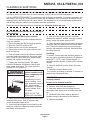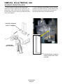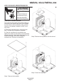
1
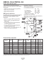
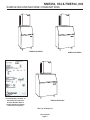
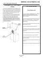
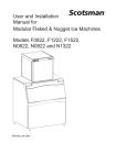
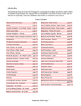
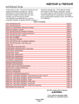
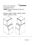
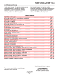
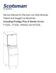
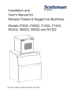
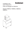
Installation and
User's Manual for
Flake and Nugget Ice Machine
Models FME504, FME804, NME454,
NME654
NME454, 654 & FME504, 804
INTRODUCTION
To the owner or user: This manual is intended to
provide you with the information needed to install,
start up, clean, and maintain this ice system.
This is a modular ice system that fits a variety of
Scotsman ice storage bins.
Table of Contents
FOR THE INSTALLER · · · · · · · · · · · · · · · · · · · · ·
SAMPLE BIN AND MACHINE COMBINATIONS · · · · · · · ·
FOR THE INSTALLER · · · · · · · · · · · · · · · · · · · · ·
FOR THE INSTALLER: Location · · · · · · · · · · · · · · · ·
FOR THE PLUMBER · · · · · · · · · · · · · · · · · · · · · ·
FOR THE ELECTRICIAN · · · · · · · · · · · · · · · · · · · ·
FOR THE INSTALLER · · · · · · · · · · · · · · · · · · · · ·
INITIAL START UP · · · · · · · · · · · · · · · · · · · · · · ·
CLEANING & SANITIZING · · · · · · · · · · · · · · · · · · ·
SENSOR MAINTENANCE · · · · · · · · · · · · · · · · · · ·
AIR COOLED MAINTENANCE · · · · · · · · · · · · · · · · ·
BEARING MAINTENANCE · · · · · · · · · · · · · · · · · · ·
AUGER MAINTENANCE · · · · · · · · · · · · · · · · · · · ·
REMOVAL AND REPLACEMENT: Bin Controls · · · · · · · ·
What to Do Before Calling for Service · · · · · · · · · · · · ·
Note this symbol when it appears.
·
·
·
·
·
·
·
·
·
·
·
·
·
·
·
·
·
·
·
·
·
·
·
·
·
·
·
·
·
·
·
·
·
·
·
·
·
·
·
·
·
·
·
·
·
·
·
·
·
·
·
·
·
·
·
·
·
·
·
·
·
·
·
·
·
·
·
·
·
·
·
·
·
·
·
·
·
·
·
·
·
·
·
·
·
·
·
·
·
·
·
·
·
·
·
·
·
·
·
·
·
·
·
·
·
·
·
·
·
·
·
·
·
·
·
·
·
·
·
·
·
·
·
·
·
·
·
·
·
·
·
·
·
·
·
·
·
·
·
·
·
·
·
·
·
·
·
·
·
·
·
·
·
·
·
·
·
·
·
·
·
·
·
·
·
·
·
·
·
·
·
·
·
·
·
·
·
·
·
·
·
·
·
·
·
·
·
·
·
·
·
·
·
·
·
·
·
·
·
·
·
·
·
·
·
·
·
·
·
·
·
·
·
·
·
·
·
·
·
·
·
·
·
·
·
·
·
·
·
·
·
·
·
·
·
·
·
·
·
·
·
·
·
·
·
·
·
·
·
·
·
·
·
·
·
Page 2
Page 3
Page 4
Page 5
Page 6
Page 7
Page 8
Page 9
Page 10
Page 11
Page 12
Page 13
Page 14
Page 15
Page 16
What to Do Before Calling for Service
If the machine is off, not making ice:
1. Check the water supply to the ice machine. The machine is designed to shut off
if there is no water to it. Check the filters if there are any.
2. Check the power supply to the machine. Reset the breaker if it is tripped.
3. If both water and power have been checked and are available, try switching the
power Off and then On. After 2 minutes the machine should restart.
If this procedure restarts the machine, service should be called the next time the
machine stops.
January 2007
Page 1
NME454, 654 & FME504, 804
FOR THE INSTALLER
These machines fit the following Scotsman
products, check sales literature for other possible
combinations:
· SB480 and extensions (with bin top KBT18)
· B842 using bin top KBT28
· B948 using bin top KBT24
NME Dispenser Applications
The NME models can be placed on and used with
certain ice and ice-beverage dispensers. Kits
are required for proper operation, see the
following list:
Installation Limitations:
This ice system is designed to be installed indoors,
in a controlled environment:
Min. Max.
Air Temperature
500F 1000F
Water Temperature
400F 1000F
Water Pressure
20 PSI 80 PSI
Voltage (for 115v model) 104
126
(Compared to the nameplate)
Operating the machine outside of the limitations is
misuse and can void the warranty.
· ID150, use adapter KBT42 and KNUGDIV
· ID200 or ID250, use adapter KBT46 and
KDIL-N-ID2
· Cornelius ED/DF200 beverage dispensers,
use KBT46 and KDIL-N-200
· Cornelius ED/DF250 beverage dispensers,
use KBT46 and KDIL-N-250
· Lancer nugget ice & beverage dispenser, use
KDIL-N-L and Lancer kit #82-3491.
SPECIFICATIONS: ICE MACHINE
Model
Number
FME504AS-1
FME504WS-1
FME804AS-1
FME804WS-1
FME804AS-32
FME804WS-32
NME454AS-1
NME454WS-1
NME654AS-1
NME654WS-1
Model Dimensions
Series
A
A
B
B
B
B
A
A
B
B
27" x 21" x 24"
same
same
same
same
same
same
same
same
same
Basic
Electrical
115/60/1
same
same
same
208-230/60/1
same
115/60/1
same
same
same
Ice Condenser Minimum Max. Refrigerant
Type
Type
Circuit
Fuse Charge:
Ampacity Size
R-404A
Flake
Flake
Flake
Flake
Flake
Flake
Nugget
Nugget
Nugget
Nugget
Air
Water
Air
Water
Air
Water
Air
Water
Air
Water
Note: Minimum Circuit Ampacity is used to determine wire size and type per national electric code.
April 2008
Page 2
15.75
14.35
19.5
18.3
10.2
10.2
15.75
14.35
19.5
18.3
20
20
30
30
15
15
20
20
30
30
22 ounces
18 ounces
24 ounces
19 ounces
24 ounces
19 ounces
22 ounces
18 ounces
24 ounces
19 ounces
NME454, 654 & FME504, 804
SAMPLE BIN AND MACHINE COMBINATIONS
FME804 ON BH550*
The Nameplate is located on
the back of the machine.
A Serial Number Plate is
located inside the cabinet,
behind the front panel.
NME654 ON BH801*
FME804 ON BH900*
*Bin Top Kit Required
January 2007
Page 3
NME454, 654 & FME504, 804
FOR THE INSTALLER
Location:
Install the machine be installed in a location where
it has enough space around it to be accessible for
service. A minimum of 6" must be allowed at the
back and sides for air circulation on air cooled
models. Try to avoid hot, dirty and crowded
locations. Be sure that the location for the machine
is within the environmental limitations.
Storage Bin:
Tip the storage bin on its back, using parts of the
carton to protect the exterior finish. Install the legs
into the threaded holes in the bottom of the bin.
Turn the leg levelers all the way in preparation for
leveling later. Return the bin to the upright
position, remove paper covering the bin gasket.
Note: Do not push bin into position, but lift it there.
Pushing a bin, especially one with ice in it, can
cause damage to the legs and the leg mounts.
Install the appropriate bin top on the bin, according
to the instructions for the bin top.
Ice Machine:
The machine is heavy, so the use of a mechanical
lift is recommended for lifting the machine high
enough to install on top of the bin. After the unit is
placed on the bin, line it up so it is even with the
back side. Secure the machine to the bin with the
hardware provided with the machine.
Remove the front panel and remove any shipping
blocks.
Note: When placing 2 of these machines on a
BH801 without the bin top, removal of the 2 service
panels facing each other will make future service
easier:
1. Remove the 2 top panel screws that will face
each other.
2. Remove the 2 service panels that will face each
other.
3. Add a strip of gasket, such as Scotsman part
number 19-0503-04, to the 2 base edges that will
face each other and around service panel space
on the 2 panels that will face each other.
When the 2 machines are placed on the bin, the
gaskets will seal the bin top area and the space
between the machines.
Water Limitations:
An ice machine is a food manufacturing plant: it
takes a raw material, water, and transforms it into
a food product, ice. The purity of the water is very
important in obtaining pure ice and in maximizing
product life. This section is not intended as a
complete resource for water related questions, but
it does offer these general recommendations:
1. Check with a water treatment specialist for a
water test, and recommendations regarding filters
and treatment.
2. In most cases, the water used to make ice
should be filtered or treated, depending upon the
water. There is no one type of water filter that is
effective in all situations. That is why a water test is
important.
RO Water Limitation: Water conductivity must be
no less than 35 microSiemens/cm.
Note:
Scotsman Ice Systems are designed and
manufactured with the highest regard for safety
and performance. They meet or exceed the
standards of UL, NSF, and CUL.
Scotsman assumes no liability or responsibility of
any kind for products manufactured by Scotsman
that have been altered in any way, including the
use of any part and/or other components not
specifically approved by Scotsman.
Scotsman reserves the right to make design
changes and/or improvements at any time.
Specifications and design are subject to change
without notice.
January 2007
Page 4
NME454, 654 & FME504, 804
FOR THE INSTALLER: Location
ALLOW AIR SPACE ON BOTH
SIDES
TWO UNITS ON ONE BIN
ALLOW ROOM
FOR AIR
CIRCULATION
AND SERVICE
ACCESS
Airflow Notice:
Air flow is in the sides and out the back.
January 2007
Page 5
NME454, 654 & FME504, 804
FOR THE PLUMBER
CONFORM TO ALL APPLICABLE CODES
Water Inlet
Drains
Air Cooled Models: Use 3 8" O.D. copper tubing to
connect cold potable water to the 3 8" male flare
fitting at the back of the cabinet. Install a hand
valve near the machine to control the water supply.
Water Treatment: In most areas, a water filter of
some type will be useful. In areas where the water
is highly concentrated with minerals the water
should be tested by a water treatment specialist,
and the recommendations of the specialist
regarding filtration and/or treatment should be
followed.
Water Cooled Models: Connect a separate 3 8"
O.D. copper line, with a separate hand valve, to
the 3 8" FPT condenser inlet at the back of the
cabinet. The water pressure to all lines must
always be above 20 PSIG, and below 80 PSIG.
Air Cooled Models: Connect a drain tube to the
¾" FPT drain at the back of the cabinet, the drain
line is of the gravity type, and ¼ inch per foot fall
is an acceptable pitch for the drain tubing. There
should be a vent at the highest point of the drain
line, and the ideal drain receptacle would be a
trapped and vented floor drain.
Use only ¾" rigid tubing.
Water Cooled Models: In addition to the above
mentioned drain, a separate condenser drain must
be installed. Connect it to the ½" condenser drain
connection at the back of the cabinet.
Storage Bin: Install a separate gravity type drain,
similar to the air cooled drain. Insulation of this
drain line is recommended.
HAND
VALVE
WATER
COOLED
VENTED
CONDENSER
INLET
AIR COOLED
MODELS
HAND
VALVE
WATER
INLET
WATER
FILTER
CONDENSER
DRAIN
VENTED
DRAIN
January 2007
Page 6
FIELD
SUPPLIED
FILTER
NME454, 654 & FME504, 804
FOR THE ELECTRICIAN
CONFORM TO ALL APPLICABLE
CODES
Connect the electrical power to the machine to the
wires in the junction box at the rear of the machine.
Check the nameplate (located on the back panel)
for the voltage requirements, and for the minimum
circuit ampacity. The machine requires a solid
chassis to earth ground wire.
The ice machine should be connected to its own
electrical circuit so it would be individually fused.
Voltage variation must remain within design
limitations, even under starting conditions.
All external wiring must conform to national,
state, and local electrical codes. The use of a
licensed electrician is required to perform the
electrical installation.
POWER
SUPPLY
FOR THE INSTALLER
Final Check List
1. Is the ice system installed indoors in a location
where the air and water temperatures are
controlled, and where they do not exceed the
design limitations?
2. Is there an electrical service disconnect within
sight of the installed machine? Has the voltage
been checked, and compared to nameplate
requirements?
3. Have all the plumbing connections been made
and checked for leaks?
4. Has the machine and bin been leveled?
WATER
COOLED
5. Is there a minimum of 6" clearance at the back
of the machine for proper service access and air
circulation?
6. Is the water pressure a minimum of 20 PSIG?
7. Has the machine been secured to the bin?
AIR
COOLED
8. Is there clearance over the top of the machine
for service access?
9. Is there a water shut off valve installed near the
machine?
10. Have all of the shipping blocks been removed?
January 2007
Page 7
NME454, 654 & FME504, 804
INITIAL START UP
Pre-Start Inspection
1. Remove the front and side service panels.
are rubbing each other. Check that the fan blade
turns freely (air cooled).
2. Check that any shipping blocks have been
removed.
4. Check that the unit is installed correctly
according to the final check list (page 8).
3. Inspect the interior of the machine for loose
screws or wires. Check that no refrigerant lines
Start Up
· The air cooled discharge pressure will depend
1. Go through the prestart inspection.
2. Open the hand valve, observe that water enters
the water reservoir, fills the tube from the reservoir
to the evaporator, and then shuts off. Check for
leaks.
3. Switch the master switch on. There will be a
short delay before the gearmotor and compressor
will start.
4. On air cooled models, the condenser will begin
to discharge warm air, on water cooled models, the
water regulating valve will open, and warm water
will be discharged into the drain.
5. The unit should soon be making ice, if desired,
the low side pressure can be checked: it should be
34 PSIG + or - 4 PSIG.
The suction line temperature at the compressor is
normally very cold, nearly to the point of frost up to
the compressor body, but not on it.
upon air and water temperatures, but should be
between 220 PSIG and 300 PSIG.
· The water cooled discharge pressure should be
constant at about 245 PSIG.
The above numbers are for new, clean machines,
you can expect to see some values higher, and
some lower between different units.
6. THERE ARE NO ADJUSTMENTS TO MAKE,
so replace the panels.
7. Clean and/or sanitize the storage bin interior,
wipe off the exterior with a clean, damp cloth.
8. Give the owner/user the service manual, instruct
him/her in the operation of the unit, and make sure
they know who to call for service.
9. Fill out the manufacturer’s registration and mail
it to Scotsman.
Water Level: The correct water level should be
checked when the machine is making ice. Check the
water level in the reservoir and compare it to the
horizontal line molded into the side of the reservoir.
The correct level should be between 18" above and 14"
below the line. If needed, bend the float arm up or
down to adjust the water level.
January 2007
Page 8
NME454, 654 & FME504, 804
CLEANING & SANITIZING
A Scotsman Ice System represents a sizable investment of time and money in any company’s business.
In order to receive the best return for that investment, it MUST receive periodic maintenance.
It is the USER’S RESPONSIBILITY to see that the unit is properly maintained. It is always preferable, and
less costly in the long run, to avoid possible down time by keeping it clean; adjusting it as needed; and by
replacing worn parts before they can cause failure. The following is a list of recommended maintenance
that will help keep the machine running with a minimum of problems.
Maintenance and Cleaning should be scheduled at a minimum of twice per year.
Note: Electrical power will be ON when doing in
place cleaning.
ICE MAKING SYSTEM: In place cleaning
1. Check and clean any water treatment devices,
if any are installed.
2. Remove screws and the front and top panels.
3. Move the ON-OFF switch to OFF.
4. Remove all the ice from the storage bin.
5. Remove the cover to the water reservoir and
block the float up.
6. Drain the water reservoir and freezer assembly
using the drain tube attached to the freezer water
inlet. Return the drain tube to its normal upright
position and replace the end cap.
7. Prepare the cleaning solution: Mix eight
ounces of Scotsman Ice Machine Cleaner with
three quarts of hot water. The water should be
between 90-115 degrees F.
Scotsman Ice Machine
Cleaner contains acids.
These compounds may
cause burns.
If swallowed, DO NOT
induce vomiting. Give
large amounts of water or
milk. Call Physician
immediately. In case of
external contact, flush
with water.
KEEP OUT OF THE
REACH OF CHILDREN.
8. Slowly pour the cleaning solution into the water
reservoir until it is full. Wait 15 minutes, then
switch the master switch to ON.
9. As the ice maker begins to use water from the
reservoir, continue to add more cleaning solution
to maintain a full reservoir.
10. After all of the cleaning solution has been
added to the reservoir, and the reservoir is nearly
empty, switch the master switch to OFF.
11. Drain the water reservoir and freezer assembly
using the drain tube attached to the freezer water
inlet. Return the drain tube to its normal upright
position and replace the end cap. Wash and rinse
the water reservoir.
Sanitizing:
To sanitize, use an approved sanitizing solution or
mix one ounce of household bleach to 2 gallons of
warm (95oF.-115oF.) water. Repeat steps 8-11
using the sanitizer solution in place of the cleaning
solution.
12. Remove the block from the float in the water
reservoir.
13. Switch the master switch to ON
14. Continue ice making for at least 15 minutes, to
flush out any cleaning solution.
DO NOT USE any ice produced from the
cleaning solution.
Be sure no ice remains in the bin.
15. Remove all ice from the storage bin.
16. Add warm water to the ice storage bin and
thoroughly wash and rinse all surfaces within the
bin.
17. Sanitize the bin interior with an approved
sanitizer using the directions for that sanitizer.
18. Replace the panels.
January 2007
Page 9
NME454, 654 & FME504, 804
SENSOR MAINTENANCE
1. The bin control is a device that senses light,
therefore it must be kept clean so it can “see”. At
least twice a year, remove the bin control sensors
from the base of the ice chute, and wipe the inside
clean, as illustrated.
2. The ice machine senses water level by a probe
located in the water reservoir. At least twice a year,
the probe should be removed from the reservoir,
and the tip wiped clean of mineral build-up.
ICE LEVEL SENSORS
SLIDE TO REMOVE
CLEAN THE
LIGHT SENSORS
Clean the Probe's Tip with ice
machine cleaner and a clean,
soft cloth.
January 2007
Page 10
NME454, 654 & FME504, 804
AIR COOLED MAINTENANCE
Hazardous Moving
Parts.
Moving fan blade can
cause personal injury.
Disconnect electrical
power before beginning.
Clean the air cooled condenser.
The air flow on this model is from front to back, so
the inside of the machine will have to be available
to clean the air cooled condenser. Use a vacuum
cleaner or coil cleaner if needed. Do NOT use a
wire brush.
A. Disconnect electrical power, and remove the
filter. The filter may be cleaned or replaced.
B. Clean the condenser: the condenser may
appear to be clean on the surface, but it can still be
clogged internally. Check with a flash light from the
front to see if light can be seen though the
condenser fins. Reverse to reassemble.
Step 2: Remove the top portion of the fan shroud.
Step 3: Clean the condenser.
Step 1: Remove the top panel.
January 2007
Page 11
NME454, 654 & FME504, 804
BEARING MAINTENANCE
The bearing in the breaker should also be checked
at least two times per year.
A. Check the bearing by:
· unscrewing the auger stud
Auger Stud
· removing the ice chute cover
Chute Cover
Cap Screw
· unscrewing the ice sweep
Ice Sweep
Inspect the bearing. There should be plenty of
grease in sight. If grease is needed the bearing
and breaker should be removed to check the
action of the bearing. It should rotate smoothly.
To remove the breaker remove the lower ice chute
then take out all four allen head cap screws and
pull the breaker off the auger and evaporator.
If the bearing only needs grease, inject grease into
the bearing using Scotsman grease needle pn
02-3559-01 and Scotsman bearing grease
cartridge, pn A36808-001. Be sure to inject grease
evenly and thoroughly.
See Removal and Replacement section to replace
bearing or seals.
Bearing
· removing the water shed & unscrewing the
breaker cover (left hand threads).
Breaker
Cover
Off
Reverse to reassemble.
January 2007
Page 12
Needle, pn
02-3559-01
NME454, 654 & FME504, 804
AUGER MAINTENANCE
4. Remove 4 allen screws holding breaker to
In some areas, the water supply to the ice maker
evaporator.
will contain a high concentration of minerals, and
that will result in an evaporator and auger
5. Pull up to remove auger.
becoming coated with these minerals, requiring a
After the auger has been removed, allow the auger
more frequent removal than twice per year. If in
to dry: if the auger is not bright and shiny, it must
doubt about the condition of the evaporator and
be cleaned.
auger, the auger can be removed so the parts can
Clean the auger and evaporator as required. DO
be inspected.
NOT HONE THE EVAPORATOR.
Note: Water filters can filter out suspended solids,
but not dissolved solids. “Soft” water may not be
the complete answer. Check with a water
FME Components
treatment specialist regarding water treatment.
ALLEN
Shown,
NME similar.
For more information on removal of these parts,
SCREWS
see REMOVAL AND REPLACEMENT.
1. To remove the auger, remove the front and top
panels.
2. Push bail clamp back from the top of the chute
cover.
BREAKER &
3. Unscrew and remove ice sweep.
BEARING &
AUGER
ASSEMBLY
ICE SWEEP
7. Replace the water seal.
8. Reverse to reassemble.
BREAKER
COVER
FME Components
Shown, NME similar.
January 2007
Page 13
NME454, 654 & FME504, 804
REMOVAL AND REPLACEMENT: Bin Controls
BIN CONTROLS (Ice Level Sensors)
1. Disconnect electrical power.
2. Remove front panel.
3. Remove control box cover.
4. Locate ice chute, at the base of the chute, in
front of and behind it are two plastic bin control
mounts.
5. Slide each bin control to the left, and in the
control box, disconnect the electrical leads
connecting the bin control to the circuit board.
6. Reverse to reassemble, be certain that the bin
controls are aligned so that the ice level sensors
are visible (centered) through the holes in the ice
chute.
ICE
CHUTE
SLIDE BIN
CONTROLS
LEFT AND
RIGHT
RESERVOIR
1. Shut off water supply.
2. Remove front panel.
3. Remove reservoir cover.
4. Disconnect water inlet tube from reservoir inlet
fitting.
5. To remove float valve, push in on “Locking Tab”
as shown and pull valve up.
Note: The plunger/seat is available as a separate
part.
6. To remove reservoir, pull up and remove water
sensor.
7. Disconnect water outlet tubes.
8. Remove the two screws holding reservoir to
bracket.
9. Remove reservoir from ice machine.
10. Reverse steps 1-9 to reassemble.
FLOAT
ASSEMBLY
LOCKING
TABS
January 2007
Page 14
Water
Sensor
SCOTSMAN ICE SYSTEMS
775 Corporate Woods Parkway, Vernon Hills, IL 60061
800-533-6006
www.scotsman-ice.com
17-3154-01