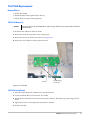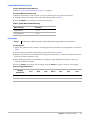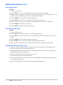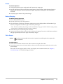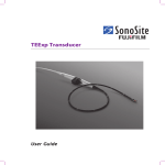
1
S Series
Ultrasound System
Service Manual
SonoSite, Inc.
21919 30th Drive SE
Bothell, WA 98021-3904
USA
Telephone: 1-888-482-9449 or 1-425-951-1200
Fax: 1-425-951-1201
SonoSite Ltd
Alexander House
40A Wilbury Way
Hitchin, Herts
SG4 OAP UK
T: +44-1462-444800
F: +44-1462-444801
Caution:
Federal (United States) law restricts this device to sale by or on the order of a physician.
S Series, SiteLink, SonoCalc, SonoHD, SonoMB, and SonoSite are registered trademarks or trademarks of SonoSite, Inc.
DICOM is the registered trademark of the National Electrical Manufacturers Association for its standards publications relating to digital communications
of medical information.
Non-SonoSite product names may be trademarks or registered trademarks of their respective owners.
Protected by U.S. patents: 5722412, 5817024, 5893363, 6135961, 6364839, 6371918, 6383139, 6416475, 6471651, 6569101, 6648826, 6962566, 7169108,
D456509, D538432. Patents pending.
P08386-01 3/2008
Copyright 2008 by SonoSite, Inc.
All rights reserved.
ii
Contents
Chapter 1: Introduction
Audience ........................................................................................................................... 1
Conventions .................................................................................................................... 1
Contact Information ..................................................................................................... 1
Chapter 2: System Overview
About the System .......................................................................................................... 3
Theory of Operation ..................................................................................................... 3
System Specifications .................................................................................................. 6
Chapter 3: Troubleshooting
Periodic Maintenance ................................................................................................11
Technical Bulletins .......................................................................................................11
System and Subsystem Diagnosis .........................................................................11
System Repair ...............................................................................................................11
Test Equipment ............................................................................................................11
Failure (Assert) Codes .................................................................................................12
Chapter 4: Replacement Procedures
Required Tools ..............................................................................................................13
Rear Cover Removal ....................................................................................................13
Rear Cover Installation ...............................................................................................14
Major System Components .....................................................................................14
Superplug Assembly Removal ................................................................................15
Superplug Installation ...............................................................................................18
Power Supply PCBA Replacement .........................................................................19
Mini-dock Assembly Replacement .......................................................................20
SD Card Daughter-card Replacement ..................................................................23
Audio I/O PCBA Replacement .................................................................................28
USB I/O PCBA Replacement .....................................................................................28
Main PCBA Replacement ..........................................................................................30
Other Major System Components .........................................................................35
LCD Replacement ........................................................................................................36
Display Backlight Inverter PCBA Replacement .................................................38
Control Panel PCBA Replacement .........................................................................39
TGC PCBA Replacement ............................................................................................41
Chapter 5: Performance Testing
Overview ........................................................................................................................43
Test Equipment ............................................................................................................43
Set Up Performance Tests .........................................................................................43
Basic Operational Tests ..............................................................................................43
2D Performance Tests ................................................................................................44
Additional Performance Tests .................................................................................46
Appendix A: Replacement Parts List
Major System Components .....................................................................................49
Other System Components .....................................................................................50
Miscellaneous System Components .....................................................................51
Fan Housing ...................................................................................................................52
Enclosure Assembly ....................................................................................................53
Transducer Nest Frame Assembly .........................................................................54
iii
Ordering Replacement Parts ...................................................................................54
Appendix B: Service Event Report
Service Event Report Form .......................................................................................56
Service Event Report Instructions .........................................................................57
Returning Products to SonoSite .............................................................................58
Index ........................................................................................................................ 59
iv
Chapter 1: Introduction
Before servicing the S Series ultrasound system, please read this manual. The information applies only to the SonoSite S Series ultrasound system product manufactured after December 7, 2007. The ultrasound system has multiple configurations and feature sets. All are described in this service manual but not every option may apply to your system. System features depend on your system configuration, transducer, and exam type.
Refer to the S Series Ultrasound System User Guide for additional information regarding safety, system controls, operation, capabilities, and specifications.
Audience
The intended audience of this manual is properly trained field and in‐house service personnel.
Conventions
These conventions are used in this service manual:
• A WARNING describes precautions necessary to prevent injury or loss of life.
• A Caution describes precautions necessary to protect the products.
• Numbered steps must be performed in a specific order.
• Bulleted lists present information in list format but do not imply a sequence.
Labeling symbols are in the user guide.
Contact Information
Questions and comments are encouraged. SonoSite is interested in your feedback regarding the service manual. If you encounter difficulty with the system, use the information in this manual to help correct the problem. If the problem is not covered here, contact SonoSite Technical Support as follows: Technical Support (USA, Canada) phone:
1-877-657-8118
Technical Support fax:
1-425-951-6700
Technical Support e-mail:
[email protected]
SonoSite Web site:
www.sonosite.com (Select Resources > Support &
Service)
International Technical Support:
Contact your local representative or call (USA)
+425-951-1330
European Service Center:
+44-(0)1462-444-800
e-mail: [email protected]
Japan Service Center:
+81-3-5304-5337
e-mail: [email protected]
Chapter 1: Introduction
1
2
Chapter 1: Introduction
Chapter 2: System Overview
About the System
The SonoSite S Series high‐resolution ultrasound system is a portable, software controlled, diagnostic ultrasound system using all digital architecture. The system is used to acquire and display high‐resolution, real‐time ultrasound data in 2D, Color Power Doppler (CPD), and color Doppler (Color) or in a combination of these modes.
The system provides measurement capabilities for anatomical structures and fetal biometry that provide information used for clinical diagnostic purposes. System features include cine review, image zoom, labeling, biopsy, measurements and calculations, and image storage, review, printing, recording capabilities.
The system/transducer is capable of exceeding a TI or an MI of 1.0 in certain operating modes or mode combinations. The system displays the current output level in terms of one of two bioeffects indices (“Mechanical Index [MI]” and “Thermal Index [TI]”) in accordance with the AIUM/NEMA Standard for Real Time Display of Thermal and Mechanical Acoustic Output Indices on Diagnostic Ultrasound Equipment.
Theory of Operation
The S Series ultrasound system has seven (7) major functional groups: • Transducer
• Acquisition Subsystem
• Processing Subsystem
• Display Subsystem
• Control Subsystem
• User Interface Subsystem
• Power Subsystem
Figure 2.1 shows the relationship of the functional groups.
Chapter 2: System Overview
3
External video to
monitor, printer
Acquisition
subsystem
RF
Bus
Processing
subsystem
AQ
Bus
Display
subsystem Video
User
interface
IrDA
Control Bus
Control
subsystem
Serial Bus
Power
subsystem
Display power
Transducer
Battery
pack
assembly
Logic power
Pulser voltage
Power
adapter
External power
Figure 2.1 SonoSite High-Resolution Ultrasound System (S Series) Block Diagram
The Transducer elements convert the pulser voltage to acoustic energy during the transmit portion of the ultrasound acquisition cycle. The elements convert the acoustic echo to voltage in the receive portion of the acquisition. The voltage developed on the transducer elements is sensed by the acquisition subsystem. The system transducers have 64 to 192 elements. The Acquisition Subsystem consists of the beamformer and interface to the transducer. The beamformer controls the timing of the transmit pulses to focus the acoustic beam. The beamformer amplifies the low‐level received echoes and controls the receive focusing. The system beamformer transmits on up to 128 elements and receives on 64 elements.
The Processing Subsystem includes capabilities for interfacing with the beamformer and performing high speed processing. The processing subsystem demodulates, filters, detects, and compresses the signal supplied by the beamformer into display information.
The Display Subsystem converts the detected ultrasound data into picture elements (pixels). The software user interface graphics are combined with the ultrasound information and converted to a video stream. The external video port supports NTSC and PAL format.
The Control Subsystem consists of the central processing unit, program and video memory, permanent image storage and retrieval memory, external communication interface ports, and connection to the user interface keys. The control software includes the acoustic power and intensity software subsystem, power group monitors, and a beamformer monitor. This software guarantees a level of patient safety by ensuring the system is operating within acoustic power and intensity limits. The User Interface Subsystem represents the software interface and form factor. The software interface is the interaction between the user and the screen layout components. The form factor is the type of physical buttons, location, and grouping of the buttons and the device size, shape, and weight. Dedicated controls are for high usage activities and grouped according to the user workflow.
4
Chapter 2: System Overview
The Power Subsystem provides the system power and protects the hardware from destructive and/or unsafe conditions by detecting failures in the system through hardware and software monitors. Detection of a fault results in disabling of the pulser supply, and signaling of an error to the Control Group. The power subsystem includes the battery pack and battery charging electronics.
Description of Operating Modes
2D Mode
2D mode is a two dimensional image of the amplitude of the echo signal. It is used for
location and measurement of anatomical structures and for spatial orientation during
operation of other modes. In 2D, a two-dimensional cross-section of a 3-dimensional soft
tissue structure such as the heart is displayed in real time. Ultrasound echoes of different
intensities are mapped to different gray scale or color values in the display. The outline of
the 2D cross-section may be a rectangle, parallelogram, trapezoid, sector, or a full circle,
depending on the particular transducer used. 2D mode can be used in combination with
any other modes.
Color
Doppler
(Color)
In color Doppler, a real-time, two-dimensional cross-section of blood flow is displayed. The
2D cross-section may be presented as a rectangle, parallelogram, trapezoid, sector, or a full
circle, depending on the particular transducer used.
The 2D cross-section is presented as a full color display, with various colors being used to
represent the velocity, both positive and negative, of the blood flow echoes. Often, to
provide spatial orientation, the full color blood flow cross-section is overlaid on top of the
gray scale cross-section of soft tissue structure (2D echo). For each pixel in the overlay, the
decision of whether to display VCD, gray scale (echo) information or a blended combination
is based on the relative strength of echoes from the soft-tissue structures and from the red
blood cells.
A high pass filter (wall filter) is used to remove the signals from stationary or slowly moving
structures. Tissue motion is discriminated from blood flow by assuming that blood is
moving faster than the surrounding tissue, although additional parameters may also be
used to enhance the discrimination. The remaining signal after wall filtering may be
averaged over time (persistence) to present a steady state image of blood flow distribution.
Variance information may also be displayed to provide information when large variance is
observed in the velocity information.
Color Power
Doppler
(CPD)
In CPD, a real-time two-dimensional cross-section of blood flow is displayed. The 2D
cross-section may be presented as a rectangle, parallelogram, trapezoid, sector, or a full
circle, depending on the particular transducer used.
The 2D cross-section is presented as a full color display, with various colors being used to
represent the power in blood flow echoes. Often, to provide spatial orientation, the full color
blood flow cross-section is overlaid on top of the gray scale cross-section of soft tissue
structure (2D echo). For each pixel in the overlay, the decision of whether to display CPD,
gray scale (echo) information or a blended combination is based on the relative strength of
echoes from the soft-tissue structures and from the red blood cells.
A high pass filter (wall filter) is used to remove the signals from stationary or slowly moving
structures. Tissue motion is discriminated from blood flow by assuming that blood is
moving faster than the surrounding tissue, although additional parameters may also be
used to enhance the discrimination. The power in the remaining signal after wall filtering
may be averaged over time (persistence) to present a steady state image of blood flow
distribution.
Chapter 2: System Overview
5
Additional System Feature Performances
Broadband
Imaging
This ultrasound acquisition system uses high resolution broadband technology in the
transmit pulsers, transducer, and receivers. The receive path can capture and process
signals over a wide spectrum, from below 2.0 MHz to beyond 10 MHz. For each
application, the transmit pulse is designed to produce an appropriate bandwidth. For
example, in 2D grayscale imaging, a wide band pulse is used to support good axial
resolution. For Doppler modes, a narrower band pulse is used, which improves the
spectral resolution of the detected Doppler signal.
In addition to transmit pulse control, programmable digital signal processing is used in
the receive path to further refine the bandwidth used to produce the final image. Digital
filters are applied to the digitized received signal to limit and shape the spectral
bandwidth used to generate the displayed output.
Biopsy
Guidance
The system can display a pair of biopsy guidelines that represent the anticipated path of
the biopsy needle. The image of an anatomical target, biopsy guidelines, a scan plane
marker, and a biopsy needle are displayed to assist in guiding the biopsy needle to the
target. The system also provides needle guidance for vascular access procedures. For
additional information, see the biopsy user guides.
Measurement
and
Calculation
Capabilities
The system offers a variety of measurements and calculations, specific to exam type and
transducer. A list of them, and author references, are in the system user guide.
Measurement accuracy is also discussed.
System Specifications
This section contains system and accessory specifications and agency approvals. The specifications for recommended peripherals can be found in the manufacturers’ instructions. See the applicable SonoSite accessory user guide for information on the accessories.
System Dimensions
Height: 15.1 in. (38.4 cm)
Width: 11.6 in. (29.5 cm)
Depth: 6.1 in. (15.5 cm)
Weight: 8.35 lbs. (3.79 kg)
Display Dimensions
Length: 8.4 in. (21.34 cm)
Height: 6.3 in. (16 cm)
Diagonal: 10.4 in. (26.4 cm)
Transducers
Note: Each of the S Series system types (S‐ICU, S‐Nerve, etc.) supports a unique combination of transducers. C11x/5‐2 MHz 11 mm curved array (6 ft./1.8 m)
C60x/5‐2 MHz 60 mm curved array (5.5 ft./1.7 m)
HFL38x/13‐6 MHz 25 mm linear array (5.6 ft./1.7 m)
ICTx/8‐5 MHz 11 mm intracavitary array (5.5 ft./1.7 m)
L25x/13‐6 MHz 25 mm linear array (7.5 ft./2.3 m)
6
Chapter 2: System Overview
L38x/10‐5 MHz 38 mm linear array (5.5 ft./1.7 m)
P21x/5‐1 MHz 21 mm phased array (6 ft./1.8 m)
Imaging Modes
2D (256 gray shades)
Color power Doppler (CPD) (256 colors)
Color Doppler (Color) (256 colors)
Image and Clip Storage
The number of images and clips you can save varies with imaging mode and file format.
Accessories
Hardware, Software, and Documentation
Battery
Biopsy Guide
Kensington Security Cable
Needle Guides
Power supply
SiteLink Image Manager 4.0
S Series Stand
System User Guide
System AC PowerCcord (10 ft / 3.1 m)
USB Keyboard
VESA Compliant Mounting
Video and printer cables
Cables
See the S Series Ultrasound System User Guide or the S Series Stand User Guide for information on cables.
Peripherals
Peripherals include the following medical grade (conforming to the requirements of EN60601‐1) and non‐medical grade (commercial) products. Manufacturer’s instructions accompany each peripheral. System setup instructions are in the S Series Ultrasound System User Guide. Instructions for using peripherals with the system are in the applicable SonoSite accessory user guide.
Medical Grade
Black‐and‐white printer
DVD recorder
Barcode Scanner
Non-Medical Grade
USB Memory Stick
Chapter 2: System Overview
7
Temperature, Pressure, and Humidity Limits
Note: The temperature, pressure, and humidity limits apply only to the ultrasound system and transducers.
Operating Limits: System
• 10–40°C (50–104°F), 15–95% R.H.
• 700 to 1060hPa (0.7 to 1.05 ATM)
Operating Limits: Battery
• 10–40°C (50–104°F), 15–95% R.H.
• 700 to 1060hPa (0.7 to 1.05 ATM)
Operating Limits: Transducer
10–40°C (50–104°F), 15–95% R.H.
Shipping/Storage Limits: System without Battery
• ‐35–65°C (‐31–149°F), 15–95% R.H.
• 500 to 1060hPa (0.5 to 1.05 ATM)
Shipping/Storage Limits: Battery
• ‐20–60°C (‐4–140°F), 0–95% R.H.*
• 500 to 1060hPa (0.5 to 1.05 ATM)
* For storage longer than 30 days, store at or below room temperature.
• 10–40°C (50–104°F), 15–95% R.H.
Shipping/Storage Limits: Transducer
• ‐35–65°C (‐31–149°F), 15–95% R.H.
Electrical
Power Supply Input: 100‐240 VAC, 50/60 Hz, 2.0 A Max @ 100 VAC.
Power Supply Output 1:
15 VDC, 5.0A Max (system)
Power Supply Output 2:
12 VDC, 2.3A Max (battery)
Combined output not exceeding 75W.
Battery
6‐cell, 11.2 VDC, 5.2 amp‐hours, rechargeable lithium ion battery pack.
Run time is up to 2 hours, depending on imaging mode and display brightness.
Electromechanical Safety Standards
EN 60601‐1:1997, European Norm, Medical Electrical Equipment–Part 1. General Requirements for Safety.
EN 60601‐1‐1:2001, European Norm, Medical Electrical Equipment–Part 1. General Requirements for Safety–Section 1‐1. Collateral Standard. Safety Requirements for Medical Electrical Systems.
EN 60601‐1‐2:2001, European Norm, Medical Electrical Equipment – Part 1‐2: General Requirements for Safety ‐ Collateral Standard: Electromagnetic compatibility ‐ Requirements and tests
EN 60601-2-37:2001 + Amendment A1:2005, European Norm, Particular requirements for the safety of ultrasonic medical diagnostic and monitoring equipment.
CAN/CSA C22.2, No. 601.1-M 90, Canadian Standards Association, Medical ElectricalEquipment.Part 1. General Requirements for Safety (including CSA 601.1 Supplement 1:1994 and CSA 601.1 Amendment 2:1998)
8
Chapter 2: System Overview
CEI/IEC 61157:1992, International Electrotechnical Commission, Requirements for the Declaration of the
Acoustic Output of Medical Diagnostic Ultrasonic Equipment.
UL 60601-1 (1st Edition), Underwriters Laboratories, Medical Electrical Equipment- Part 1: General
Requirements for Safety.
EMC Standards Classification
EN 60601‐1‐2:2001, European Norm, Medical Electrical Equipment. General Requirements for Safety‐Collateral Standard. Electromagnetic Compatibility. Requirements and Tests.
CISPR11:2004, International Electrotechnical Commission, International Special Committee on Radio Interference. Industrial, Scientific, and Medical (ISM) Radio‐Frequency Equipment Electromagnetic Disturbance Characteristics‐Limits and Methods of Measurement.
The Classification for the SonoSite system, SiteStand, accessories, and peripherals when configured together is: Group 1, Class A.
Airborne Equipment Standards
RTCA/DO-160E:200 4, Radio Technical Commission for Aeronautics, Environmental Conditions and Test Procedures for Airborne Equipment, Section 21.0 Emission of Radio Frequency Energy, Category B.
DICOM Standard
NEMA PS 3.15: 2000, Digital Imaging and Communications in Medicine (DICOM)‐Part 15: Security Profiles.
HIPAA Standard
The Health Insurance and Portability and Accountability Act, Pub.L. No. 104‐191 (1996).
45 CFR 160, General Administrative Requirements.
45 CFR 164, Security and Privacy.
Chapter 2: System Overview
9
10
Chapter 2: System Overview
Chapter 3: Troubleshooting
This chapter contains information to help you correct problems with system operation and provides instructions on the proper care of the system, transducer, and accessories.
Periodic Maintenance
There is no recommended periodic or preventive maintenance required for the system, transducers, or accessories. There are no internal adjustments or alignments required. There are no functions that require periodic testing or calibration. Performance tests are described in Chapter 5, “Performance Testing,” of this manual. Performing maintenance activities not described in this manual may void the product warranty.
Local regulations may require electrical safety testing.
Contact SonoSite Technical Support for any maintenance questions.
Technical Bulletins
Product Technical Bulletins describing known system issues are periodically placed on SonoSite.com. Select Resources > Support & Service, and then follow the links to S Series support documents. System and Subsystem Diagnosis
This section covers basic diagnostic and troubleshooting procedures you may follow if the system does not operate properly. To diagnose system failures, consult the referenced diagnostic figures that follow or SonoSite Technical Support.
Table 3.1: Troubleshooting Subassemblies and Diagnostic Figures
Subassemblies
Diagnostic Figures or Table
Display
TBA
Battery
TBA
Control Panel
TBA
System Repair
The system is repairable through subassembly replacement or through replacement of parts as recommended by SonoSite in Chapter 4, “Replacement Procedures.” Component level repair of Printed Circuit Board Assemblies is performed only at the SonoSite repair facility. Replacement of board level components by unauthorized service facilities voids the SonoSite warranty.
Test Equipment
Test equipment is not required for this troubleshooting section. Troubleshooting test aids include an external monitor and a spare battery.
Chapter 3: Troubleshooting
11
Failure (Assert) Codes
ʺAssertʺ or ʺAssert Codeʺ are software error codes that are generated by all Sonosite products when certain hardware or software fault conditions exist. Providing the Assert Code to the Technical Support Group may assist in quicker and more accurate fault diagnosis. Hardware Assert Codes typically cannot be reset and will usually require Main PCBA replacement. Many software Assert Codes can be reset and the system may recover and operate normally. Handling Assert Codes
1 Record the Assert Code. The Assert Code is a four or five digit number inside of parentheses on the maintenance screen (Blue screen with screwdriver symbol). See Figure 3.1.
Assert Code
Figure 3.1 Maintenance Screen with Assert Code
2 Press and release the Power button to power the system down.
3 Press the Power button again to power the system up.
• If the system powers up normally, it has recovered from the fault (software assert) and you may use the system.
• If the Assert Code remains, corrective action must be taken; usually replacement of the main PCBA is required. Contact SonoSite Technical Support for assistance and to obtain repair parts.
If the Power button is not functional, all sources of power must be removed to allow the system to power down. I.e., disconnect AC power and remove the battery.
12
Chapter 3: Troubleshooting
Chapter 4: Replacement Procedures
Caution:
Always use correct ESD procedures. ESD damage is cumulative and may not be noticeable at first.
Initial ESD symptoms may be slightly degraded performance or image quality.
Required Tools
• #1 Phillips screwdriver
• #1 Flat Blade screwdriver
• 2mm Allen Key
• Torque screwdriver, 2.0–10.0 inch pounds (0.23–1.1 Newton‐meter)
• Scissors
• Cotton swabs (Q Tips)
• Anti‐static mat
• Wrist grounding strap
Rear Cover Removal
Removal of the Rear Cover is required to access all other system components.
1 Remove the battery from the system.
2 Remove the seven screws from the Rear Cover as shown in Figure 4.1.
Screws (7x)
Battery removed
Figure 4.1 Rear Cover Removal
Chapter 4: Replacement Procedures
13
Rear Cover Installation
1 Insert the top of the Rear Cover under the top cap, and press down to mate with the Front Enclosure. 2 Install the seven screws removed from the Rear Cover and torque to 5.5 inch/pounds. 3 Install the battery.
Major System Components
All of the components shown below, including the frame they are mounted on, are called the Superplug Assembly. The Superplug Assembly cannot be ordered but is referenced throughout these instructions. Removal of the Superplug Assembly is required to replace many of the other system components.
Mini-dock Assembly
SD Card
Daughter
Card
(Shown
without
Copper
Tape)
USB I/O PCBA
Audio I/O PCBA
Power Supply
Frame
Figure 4.2 Major System Components
14
Chapter 4: Replacement Procedures
Power Supply
PCBA
(Shown with Shield
Removed)
Main PCBA
Nest Frame
Assembly
Superplug Assembly Removal
Caution:
Improper removal of the cable connectors could damage components on the Main PCBA. Use
extreme caution when removing the connectors.
1 Remove the Rear Cover as described in “Rear Cover Removal” on page 13.
2 Disconnect the five cable connectors as shown in Figure 4.3.
Use extreme caution when removing this
connector to prevent damage to the
components underneath.
Disconnect connectors (5x).
Figure 4.3 Disconnecting Superplug Cables
Chapter 4: Replacement Procedures
15
3 Remove the nine Superplug Assembly mounting screws as shown in Figure 4.4.
Remove 9 Superplug
Assembly screws.
Figure 4.4 Superplug Assembly Screw Removal
16
Chapter 4: Replacement Procedures
Caution:
There is a cable between the bottom of the Superplug Assembly and the LCD below it. Use
caution when removing the Superplug Assembly to prevent damage to the cable.
4 Disconnect the Display Wire Harness from the bottom of the Superplug Assembly as shown in Figure 4.5.
5 Remove the Superplug Assembly from the system.
Figure 4.5 Display Wire Harness between LCD and Superplug Assembly
Chapter 4: Replacement Procedures
17
Superplug Installation
Caution:
Use extreme caution when installing the Display Wire Harness to prevent irreparable damage to
the LCD.
1 Carefully reconnect the Display Wire Harness between the bottom of the Superplug Assembly and the LCD as shown in Figure 4.6.
2 Insert the Superplug Assembly into the system enclosure.
Use extreme caution when installing the
Display Wire Harness to prevent damage to
this component.
Figure 4.6 Display Wire Harness Installation
3 Reinstall the nine screws as shown in “Superplug Assembly Screw Removal” on page 16, and torque to 5.5 inch/pounds (.622 Newton‐meters).
4 Reconnect the cables as shown in Figure 4.3 on page 15.
5 Reinstall the Rear Cover as described in “Rear Cover Installation” on page 14.
18
Chapter 4: Replacement Procedures
Power Supply PCBA Replacement
Note: Power Supply PCBA replacement does not require removal of the Superplug Assembly.
Required Parts
• P08850 Service Assembly, Power Supply, M‐Turbo / S Series
Power Supply PCBA Removal
1 Remove the Power Supply PCBA Shield (not shown). 2 Remove the seven screws as shown in Figure 4.7.
3 Remove the Power Supply PCBA from the Power Supply mounting frame.
Screws (7x)
Figure 4.7 Power Supply PCBA Screws
Power Supply PCBA Installation
1 Insert one screw into each corner of the replacement Power Supply PCBA. 2 Place the replacement PCBA into the Power Supply mounting frame using the screws to properly align the PCBA to the connector on the Main PCBA. 3 Install the remaining screws, and torque the screws to 5.5 inch/pounds (.622 Newton‐meters).
Caution:
Inspect the Power Supply Shield to ensure that none of the contacts are bent. Improper contact between the shield and the Power Supply Frame can cause image noise problems.
4 Reinstall the Power Supply shield.
Chapter 4: Replacement Procedures
19
Mini-dock Assembly Replacement
Required Parts
• P09138 Service Assembly, Internal Mini‐dock, S Series
Mini-dock Assembly Removal
1 Remove the Rear Cover as described in “Rear Cover Removal” on page 13.
2 Remove the Superplug Assembly as described in “Superplug Assembly Removal” on page 15.
Caution:
The connector for the Mini-dock Assembly ribbon cable is fragile and will require replacement of
the Mini-dock Assembly if broken.
3 Disconnect the mini‐dock ribbon cable by gently lifting up on the connector latch as shown in Figure 4.8. Main PCBA Connector
Connector Latch Closed
Figure 4.8 Mini-dock Ribbon Cable
20
Chapter 4: Replacement Procedures
Ribbon Cable
Connector Latch Open
4 Remove the three Mini‐dock Assembly mounting screws as shown in Figure 4.9.
5 Disconnect the P1 and P2 cable connectors from the Mini‐dock Assembly as shown in Figure 4.9.
P2
P1
Mini-dock Assembly
Mounting Screws (3x)
Disconnect P1 and
P2 Connectors
Figure 4.9 Mini-dock Assembly Mounting Screws
6 Carefully separate the Mini‐dock Assembly from the Main PCBA as shown in Figure 4.10.
Figure 4.10 Mini-dock Assembly Removed
Chapter 4: Replacement Procedures
21
Mini-dock Assembly Installation
1 Carefully align the replacement Mini‐dock Assembly connector to the Main PCBA Connector and push firmly to engage the connectors. 2 Reinstall the three Mini‐dock Assembly mounting screws as shown in Figure 4.9 on page 21. Tighten the screws to 8.0 inch/pounds (.904 Newton‐meters).
3 Reconnect the P1 and P2 cable connector as shown in Figure 4.9 on page 21.
4 Reconnect the ribbon cable as shown in Figure 4.8 on page 20.
5 Reinstall the Superplug Assembly as described in “Superplug Installation” on page 18.
6 Reinstall the Rear Cover as described in “Rear Cover Installation” on page 14.
22
Chapter 4: Replacement Procedures
SD Card Daughter-card Replacement
Note: SD Card Daughter‐card replacement does not require removal of the Superplug Assembly.
Required Parts
• P07442 SD Card Daughter‐Card
• P09216 Copper Tape (1” x 3.5mil), approximately 15” is required
• P00870 Kapton Tape (1” x 1mil), approximately 6” is required ‐ Kapton tape is a plastic tape used for electrical isolation.
• Cotton swabs (Q Tips)
• Scissors
SD Card Daughter-card Removal
1 Remove the Power Supply PCBA as described in “Power Supply PCBA Removal” on page 19
2 Carefully remove the copper tape from the SD Card Daughter‐card indicated in Figure 4.11.
SD Card Daughter-card Copper Tape
Figure 4.11 SD Card Daughter-card Copper Tape
Chapter 4: Replacement Procedures
23
3 Remove the four screws that hold down the SD Card Daughter‐card as shown in Figure 4.12. Note the location of the one longer screw for reassembly.
Power Supply
Frame Screw
Long Screw
SD Card Daughter-card
Screws (4x)
Figure 4.12 SD Card Daughter-card Screws
4 Gently lift the SD Card Daughter‐card straight up and away from the Main PCBA.
Caution:
Failure to reinstall the SD Cards in the same location from which they were removed will result in
loss of patient information and may prevent the operation of any transducer. Record the location
of any SD Cards removed and ensure that they are reinstalled in the same location.
5 Record the location of the SD Cards for reference when reinstalling.
24
Chapter 4: Replacement Procedures
SD Card Daughter-card Installation
Note: The following procedure assumes that the SD Cards are being removed from the old daughter‐card and installed on the new daughter‐card. This ensures any images on the cards will remain with the system.
Caution:
Failure to reinstall the SD Cards in the same location from which they were removed will result in
loss of patient information and may prevent the operation of any transducer. Record the location
of any SD Cards removed and ensure that they are reinstalled in the same location.
1 Remove the SD Cards from the old daughter‐card, and install into the SD Card holders on the bottom of the replacement Daughter‐card as shown in Figure 4.13.
2 Secure the SD Cards to the holders using Kapton tape as shown in Figure 4.13.
3 Rub the Kapton Tape with a cotton swab (Q‐Tip) to ensure that the tape is in contact with the SD Cards.
Kapton Tape
Figure 4.13 SD Card Installation (Bottom View)
4 Install a strip of Kapton tape on the top of the SD Card Daughter‐card as shown in Chapter 4.14. This protects the components underneath from the copper tape.
Kapton Tape
Figure 4.14 SD Card Daughter-card with Kapton Tape
5 Remove the last Power Supply Frame screw as shown in Figure 4.12 on page 24.
6 Remove the Power Supply Frame from the Main PCBA.
7 Ensure all old copper tape has been removed before proceeding.
Chapter 4: Replacement Procedures
25
8 Apply one strip of 1” x 5” self‐adhesive copper tape to the edge of the Power Supply Frame as shown in Figure 4.15.
9 Cut the copper tape away from the ventilation holes in the frame, or failure of the Main PCBA will occur.
Copper Tape Applied to
Side of Power Supply
Frame
Ventilation Cut-outs
Power Supply Frame
Screw Location
Figure 4.15 Copper Tape Installation
10Place the Power Supply Frame back onto the Main PCBA.
11Reinstall the Power Supply PCBA as described in “Power Supply PCBA Installation” on page 19.
12Install the SD Card Daughter‐card onto the Power Supply PCBA Frame using the alignment holes/pins on the card and frame as shown in Figure 4.16. Caution:
Improper installation of the SD Card Daughter-card will cause all or part of the internal image
storage memory to be unrecognized by the system.
SD Card
Daughter-card
Alignment Pins
Figure 4.16 SD Card Daughter-card Alignment
26
Chapter 4: Replacement Procedures
13Install the daughter‐card screws ensuring the proper location of the longer screw as shown in Figure 4.12 on page 24. Torque the screws to 5.5 inch/pounds (.622 Newton‐meters).
14Fold the copper strip installed in Step 8 over the top of the SD Card Daughter‐card as shown in Figure 4.17.
15Install a second strip of 1” x 5” self‐adhesive copper tape over the SD Card Daughter‐card on the edge closest to the Power Supply Frame as show in Figure 4.17.
Figure 4.17 Copper Tape Installation - 2nd Strip
16Install a third strip of 1” x 5” self‐adhesive copper tape over the other two strips as shown in Figure 4.18.
Figure 4.18 Copper Tape Installation - 3rd Strip
Chapter 4: Replacement Procedures
27
17Activate the adhesive on the copper strips by rubbing the entire surface of the copper tape using a cotton swab (Q Tip) as shown in Figure 4.19.
Rub the entire surface of the
copper tape to ensure proper
adhesion.
Figure 4.19 Activating Copper Tape Adhesive
Audio I/O PCBA Replacement
Required Parts
• P08670 Audio I/O PCBA
• P07786 I/O Cable (optional)
Audio I/O PCBA Removal
1 Disconnect the cable from the Audio I/O PCBA.
2 Remove the two screws that secure the Audio I/O PCBA. 3 Remove the Audio I/O PCBA from the system enclosure.
Audio I/O PCBA Installation
1 Install the replacement Audio I/O PCBA.
2 Reinstall the two screws into the Audio I/O PCBA, and torque to 5.5 inch/pounds (.622 Newton‐meters).
3 Reattach the cable.
USB I/O PCBA Replacement
Required Parts
• P08671 USB I/O PCBA
• P07786 I/O Cable (optional)
USB I/O PCBA Removal
1 Disconnect the cable from the USB I/O PCBA.
2 Remove the two screws that secure the USB I/O PCBA. 3 Remove the USB I/O PCBA from the system enclosure.
28
Chapter 4: Replacement Procedures
USB I/O PCBA Installation
1 Insert the replacement USB I/O PCBA into the system enclosure.
2 Reinstall the two screws into the USB I/O PCBA, and torque to 5.5 inch/pounds (.622 Newton‐meters).
3 Reattach the cable.
Chapter 4: Replacement Procedures
29
Main PCBA Replacement
Required Parts
• P09135 Service Assembly, Main PCBA, S Series
• Nest Frame Assembly, S Series (Optional. Order these parts individually as necessary.)
• P00364 Connector, Interposer (Qty 8)
• P00924 Screw, Shoulder, Thrust Plate (Qty 4)
• P00353 Wear Plate
• P00646 Spring, Thrust Plate (Qty 4)
• P07750 Nest Frame
• P03834 Shield, Perimeter, Long (Qty 2)
• P03833 Shield, Perimeter, Short (Qty 2)
• P08200 M2.5‐.45x10 Socket Head Cap Screw (Qty 4)
Main PCBA Removal
1 Remove the Rear Cover as described in“Rear Cover Removal” on page 13.
2 Remove the Superplug Assembly as described in “Superplug Assembly Removal” on page 15.
3 Remove the Power Supply PCBA as described in “Power Supply PCBA Removal” on page 19.
4 Remove the Mini‐dock Assembly as described in “Mini‐dock Assembly Removal” on page 20.
5 Remove the SD Card Daughter‐card as described in“SD Card Daughter‐card Removal” on page 23.
6 Remove the seven screws as shown in Figure 4.20.
Screws (7x)
Figure 4.20 Main PCBA Screw Removal
30
Chapter 4: Replacement Procedures
7 Turn the Superplug Assembly over to expose the Nest Frame Cap Screws as shown in Figure 4.21.
8 Remove the 4 Socket Head Cap Screw as shown in Figure 4.21. This releases the Nest Frame and will allow the Main PCBA to be removed from the Superplug Assembly.
2.5mm Socket Head Cap
Screws (4x)
Figure 4.21 Nest Frame Assembly Socket Head Cap Screws
9 Remove the Main PCBA from the Superplug Assembly.
Chapter 4: Replacement Procedures
31
Main PCBA Installation
1 Set the replacement Main PCBA onto the Superplug Assembly frame. Refer to Figure 4.22 for correct orientation of the Main PCBA.
2 Loosely install two Main PCBA screws in the locations shown in Figure 4.22.
Loosely install
two screws.
Figure 4.22 Main PCBA Installation
3 Observe the alignment features of the Main PCBA and the Nest Frame Assembly as shown in Figure 4.23.
The Nest Frame Assembly must be properly installed using the alignment pins to ensure proper transducer operation.
These alignment features must be properly aligned or the
Nest Frame Assembly will not sit flat on the Main PCBA.
Figure 4.23 Nest Frame Alignment
32
Chapter 4: Replacement Procedures
4 Rotate the Superplug Assembly on edge as shown in Figure 4.24. This allows the Nest Frame Assembly to be mated to the Main PCBA without the Nest Frame interposers falling out.
5 Seat the Nest Frame Assembly firmly against the Main PCBA and hold in place to install the retaining screws. Figure 4.24 Installing Nest Frame
6 Loosely reinstall the four 2.5mm cap screws as shown in Figure 4.25.
2.5mm Socket Head Cap
Screws (4x)
Figure 4.25 Nest Frame Cap Screws
Chapter 4: Replacement Procedures
33
7 Loosely install the five remaining screws in the Main PCBA as indicated in Figure 4.26.
Caution:
Failure to properly align the Main PCBA as indicated in the following steps will prevent
transducers and the battery from properly attaching to the system.
8 With all retaining screws loosely installed, move the Main PCBA on the Superplug Assembly to the upper right corner as shown in Figure 4.26.
Move the Main PCBA in this
direction as far as it will travel
Loosely install
five screws
Figure 4.26 Install Remaining Screw
9 Tighten the Phillips head screws on the top of the Main PCBA, and torque to 5.5 inch/pounds (.622 Newton‐meters).
10Tighten the Cap Screws on the back of the Superplug Assembly and torque to 4.5 inch/pounds (.508 Newton‐meters).
11Reinstall the Power Supply PCBA as described in “Power Supply PCBA Installation” on page 19.
Caution:
Failure to reinstall the SD Cards in the same location from which they were removed will result in
loss of patient information and may prevent the operation of any transducer. Record the location
of any SD Cards removed and ensure that they are reinstalled in the same location.
12Reinstall the SD Card Daughter‐card as described in “SD Card Daughter‐card Installation” on page 25.
13Reinstall the Mini‐dock Assembly as described in “Mini‐dock Assembly Installation” on page 22.
14Reinstall the Superplug Assembly as described in “Superplug Installation” on page 18.
15Reinstall the Rear Cover as described in “Rear Cover Installation” on page 14.
34
Chapter 4: Replacement Procedures
Other Major System Components
TGC PCBA
LCD Mounting
Frame Screws (4x)
Display Backlight
Inverter PCBA
LCD with Mounting
Frame
Control Panel
PCBA
Figure 4.27 Other Major System Components
Chapter 4: Replacement Procedures
35
LCD Replacement
Required Parts
• P07068 LCD, 10.4”. This part number is for the LCD monitor only. Cables and mounting hardware are not included.
• P06973 Display Wire Harness (optional)
LCD Removal
1 Disconnect the wire harness connecting the LCD and the Display Backlight Inverter PCBA.
2 Remove the four LCD frame mounting screws shown in Figure 4.27. 3 Remove the LCD mounting frame from the enclosure.
4 Remove the four screws that mount the LCD to the mounting frame as shown in Figure 4.28.
LCD Mounting
Screws (4x)
Figure 4.28 LCD Mounting Screws
36
Chapter 4: Replacement Procedures
LCD Installation
1 Insert the replacement LCD into the mounting frame.
2 Reinstall the four screws that mount the LCD to the frame as shown in Figure 4.28. Torque the screws to 5.5 inch/pounds (.622 Newton‐meters).
3 Reinstall the mounting frame with LCD into the system enclosure.
4 Reinstall the mounting frame screws as shown in Figure 4.27, and torque to 8.0 inch/pounds (.904 Newton‐meters).
Caution:
Use extreme caution when installing the Display Wire Harness to prevent irreparable damage to
the LCD.
5 Reconnect the Display Wire Harness as shown in Figure 4.29.
Use extreme caution when installing the
Display Wire Harness to prevent damage to
this component.
Figure 4.29 Display Wire Harness Installation
Chapter 4: Replacement Procedures
37
Display Backlight Inverter PCBA Replacement
Required Parts
• P07445 Display Backlight Inverter PCBA
• P02172 Backlight Inverter Wire Harness (optional)
• P08086 LCD Extension Cable (optional)
Display Backlight Inverter PCBA Removal
1 Disconnect the wire harness connecting the Backlight Inverter PCBA and the LCD.
2 Remove the two screws that mount the Backlight Inverter PCBA to the system enclosure as shown in Figure 4.30. 3 Carefully remove the Backlight Inverter PCBA from the enclosure.
P08086
Backlight Inverter Mounting
Screws (2x)
P02172
Figure 4.30 Backlight Inverter Mounting Screws
Display Backlight Inverter PCBA Installation
1 Insert the replacement Backlight Inverter PCBA into the system enclosure.
2 Reinstall the two screws that mount the Backlight Inverter PCBA, and torque to 5.5 inch/pounds (.622 Newton‐meters). 3 Reconnect the cables. 38
Chapter 4: Replacement Procedures
Control Panel PCBA Replacement
Required Parts
• P07686 S Series Control Panel PCBA
• P08406 Snap Dome
• P02308 12 Pin 3” Jumper Cable (optional)
• P07796 24 Pin 4” Jumper Cable (optional)
Control Panel PCBA Removal
Caution:
The connectors for the Control Panel PCBA ribbon cables are fragile and will require replacement
of the Control Panel PCBA if broken.
1 Disconnect all cables from the Control Panel PCBA.
2 Remove the six mounting screws as shown in Figure 4.31. 3 Remove the Control Panel PCBA from the system enclosure.
P2308
P02308
P07796
Control Panel Mounting
Screws (6x)
Figure 4.31 Control Panel PCBA
Chapter 4: Replacement Procedures
39
Control Panel PCBA Installation
1 Access the rear of the replacement Control Panel PCBA. The replacement Control Panel PCBA does not include the P08406 Snap Dome required for proper operation of the touchpad Select button. The P08406 Snap Dome must be ordered separately or reused from the old control panel.
2 Use Scotch tape to secure the Snap Dome to the center contact on the rear of the Control Panel PCBA as shown in Figure 4.32.
Control Panel
Snap Dome
Scotch Tape
Figure 4.32 Control Panel Snap Dome Installation
3 Insert the replacement Control Panel PCBA into the system enclosure.
4 Reinstall the six mounting screws, and torque to 5.5 inch/pounds (.622 Newton‐meters).
5 Reconnect all cables.
40
Chapter 4: Replacement Procedures
TGC PCBA Replacement
Required Parts
• P07762 TGC PCBA
• P07782 Encoder Knobs (optional) (not shown)
• P07785 12 Pin 5” Jumper Cable (optional)
TGC PCBA Removal
Caution:
The connector for the TGC PCBA ribbon cable is fragile and will require replacement of the TGC
PCBA if broken.
1 Disconnect the cable from the TGC PCBA.
2 Remove the knobs from the front of the control panel.
3 Remove the three TGC PCBA screws shown in Figure 4.33. 4 Remove the TGC PCBA from the system enclosure.
P07785
LCD Mounting
Screws (3x)
Figure 4.33 TGC PCBA
TGC PCBA Installation
1 Insert the replacement TGC PCBA into the system enclosure.
2 Loosely install the three screws into the TGC PCBA.
3 Attach the Encoder Knobs to the front of the system enclosure. This helps to properly align the TGC PCBA.
4 Tighten the screws to 5.5 inch/pounds (.622 Newton‐meters).
5 Reattach the cable.
Chapter 4: Replacement Procedures
41
42
Chapter 4: Replacement Procedures
Chapter 5: Performance Testing
Overview
WARNING:
Critical Test Function — A failure of the system functions tested in this section could adversely
affect the safety or effectiveness of the system. While performing the steps in this section, verify
that the images on the system display and on the external monitor are acceptable.
To obtain 2D images, SonoSite recommends using the RMI 413A Soft Tissue Phantom or the RMI 403 GS Multipurpose Phantom. A .7db/cm phantom is required for performing penetration measurements. Any equivalent .7db/cm Phantom is acceptable.
When making penetration measurements on a phantom, apply the phantom reference value and tolerance to the measurement.
Some features and capabilities are optional and therefore may be unavailable to test.
Test Equipment
• SonoSite ultrasound system under test
• Transducer compatible with the system under test
• RMI 413A Soft Tissue Phantom, RMI 403 GS Multipurpose Phantom, or equivalent. A referenced .7db/cm phantom is required for performing penetration measurements.
• Video printer
• Acoustic gel
Set Up Performance Tests
Set Up Performance Tests
1 Attach a compatible transducer to the system under test.
2 Select Gen for optimization type.
3 Couple the transducer to the phantom, adjusting gain settings and transducer for a proper phantom image (e.g., pins are high‐level echoes positioned in straight lines; cysts are sonolucent, edges are sharp, and graphite particles of the phantom are mid‐grays).
Basic Operational Tests
Basic System Operation Tests
1 Verify that the correct transducer name appears in the upper right corner of the system display.
2 Verify proper date and time.
3 Verify that the scan plane orientation mark in the image located near the skinline corresponds to element #1 on the transducer. To test, put your finger on the probe and run it across the transducer face. Your finger touching the transducer face should appear at the orientation mark on the display image format.
4 Verify that all controls and buttons smoothly over their full range and that the system responds properly.
5 Verify that all of the softkeys are functional. 6 Verify that as the Gain controls are increased and decreased, there is a corresponding increase and decrease in echo intensity.
Chapter 5: Performance Testing
43
2D Performance Tests
2D Performance / Image Quality
Test 2D Performance and Image Quality
1 Adjust the position of the transducer on the phantom.
2 With the array pointing down and the orientation mark to the operator’s left, element #1 corresponds with the left side of the array.
3 Use the 2D system controls to obtain a clear image that shows both the horizontal and vertical rows of pins.
4 Verify that the ultrasound image appears uniform in both the axial and lateral direction, with no dropouts or intensity variations.
5 Verify that the cystic structure at the focal zone is clearly differentiated from the surrounding tissue and is echo‐free, while solid tissue with numerous echo sources appears solid.
6 Press the Freeze key and then save the image. Press the Freeze key again to return to live imaging.
Axial Measurement Accuracy
Note: Measurements must be performed while the image is frozen.
Set Up Axial Measurement Accuracy
1 Acquire the image.
2 Press the Freeze key.
3 Press the Calipers key. The caliper appears. (See the S Series Ultrasound System User Guide, if necessary, for caliper operation.)
4 Use the touchpad to position one of the calipers.
5 Press the Select key (button under the touchpad) to fix the caliper and enable the other caliper.
6 Use the touchpad to move the other caliper. The results update as you move the caliper, and the measurement is complete when you finish moving the calipers. (Press the Select key to alternate the active caliper, and adjust the measurement with the touchpad.)
Test Axial Measurement Accuracy
1 Measure the distance, center to center, of any two pins that are 5‐12 cm apart vertically.
2 Verify that the distance measured is within the tolerance listed in Table 1 on page 45.
44
Chapter 5: Performance Testing
Lateral Measurement Accuracy
Set Up Lateral Measurement Accuracy
Perform “Set Up Axial Measurement Accuracy” on page 44.
Test Lateral Measurement Accuracy
1 Measure the distance, center to center, of any two pins that are 4‐10 cm apart horizontally.
2 Verify that the distance measured is within the tolerance listed in Table 1.
3 Press the Freeze key to return the system to live 2D mode.
Table 1: System Measurement Accuracy
Measurements
Tolerance
Axial Distance
+/- 2%
Lateral Distance
+/- 2%
Penetration
Caution:
A referenced .7db/cm phantom is required for performing penetration measurements
Test Penetration
1 Adjust the system controls to obtain a clear image that shows the limits of echo penetration as shown in Table 2.
2 Set the system optimization mode settings to the values shown in Table 2.
3 Measure from the center of the skinline to the deepest vertical position—where the scatter echoes start to break up and tissue definition is lost.
4 When making penetration measurements on a phantom, apply the phantom reference value and tolerance to the measurement.
5 Press the Freeze key and then save the image. Press the Freeze key again to return to live imaging.
Table 2: Imaging Performance
Imaging
Performance
C11x
C60x
ICTx
HFL38
L25x
L38x
P21x
Optimization
Gen
Gen
Gen
Res
Res
Res
Pen
2D Penetration
6.8cm
14.0 cm
6.5 cm
4.5 cm
4.3 cm
5.7 cm
21.0 cm
Chapter 5: Performance Testing
45
Additional Performance Tests
Color Doppler (Color)
Test Color
1 Connect any transducer.
2 Press the Color key. “Color” should be annotated in the top left corner of the display.
3 A Region of Interest (ROI) box is displayed on top of the grayscale image. Use the touchpad to move the CPD ROI. Verify that the ROI moves to the new position on the display.
4 Adjust the Depth control for minimum depth in the image.
5 Adjust the Gain control so that color speckles just appear inside the ROI box.
6 Gently tap the face of the transducer and observe that the ROI box fills with color information.
7 Press the Freeze key and then save the image. 8 Press the Freeze key again to return to live imaging.
Color Power Doppler (CPD)
Test CPD
1 Connect any transducer.
2 Press the Color key. A ROI box appears on top of the grayscale image.
3 Press the Color on the left to switch to CPD. “CPD” should be annotated in the top left corner of the display.
4 Adjust the Depth control for minimum depth in the image.
5 Adjust the Gain control so that color speckles appear just inside the ROI box.
6 Gently tap the face of the transducer, and observe that the ROI box fills with color information.
Image Quality Verification Test/Livescan
• Products with replaced subassemblies, or products that have been otherwise disassembled, should undergo an Image Quality Verification Test/Livescan.
• The Image Quality Verification Test/Livescan should be performed after successfully completing all applicable performance tests listed above.
• The test is completed before returning the system to service.
• A certified sonographer should perform the test.
• The Livescan test performed is at the discretion of the sonographer and will represent their acceptance of a successful service event.
• Review all saved images, and verify that the images are displayed properly.
46
Chapter 5: Performance Testing
Printer
Test Printer Operation
1 Verify proper printer type is configured in the Connectivity setup page.
1 Press the print button and verify that the printer begins to print an image. After the image begins to emerge from the printer, press the print button again. The printer should ignore the second print command.
2 Verify the proper content of the printed image.
Battery Charging
Test Battery Charging Operation
1 Insert a battery into the system.
2 Press the power key to turn the system on. 3 Allow the battery to discharge. The battery indicator icon on the display, below the Transducer Type indicator, extinguishes from left to right as the battery discharges. Note: The Power and Sleep delay settings in the Audio, Battery setup page should be selected to Off to properly perform this test. The battery may take 1–2 hours to discharge.
4 Attach the AC power cord to the power connector.
5 Note that the battery indicator indicates that the battery is charging. The sections of the battery indicator will light sequentially from left to right as the battery charges.
Video Output
Caution:
Use only the recommended video monitor or printer when verifying the video output at the
video receptacle.
Test Video Output
1 Attach an external video monitor to the video connector using the video cable.
2 Turn on the system power, and verify that the video on the external monitor matches the video on the system display.
If the video does not appear similar, or there is no display on the external monitor, see Chapter 3, “Troubleshooting,” for troubleshooting procedures.
Chapter 5: Performance Testing
47
48
Chapter 5: Performance Testing
Appendix A: Replacement Parts List
The following tables contain all the field‐replaceable parts for the S Series ultrasound system. Quantities are one unless otherwise noted.
Major System Components
1
7
6
5
4
3
2
Table 1: Major System Components
Item Number
Part Number
Description
1
P09138
Mini-dock Assembly
2
P09135
Service Assembly Main PCBA, S Series
Note: This part does not include the transducer nest frame assembly. The nest frame from the old Main PCBA should be reused unless determined to be defective. Those parts must be ordered separately if needed to complete the replacement of the Main PCBA.
3
P08850
Service Assembly, Power Supply
4
P08670
Audio I/O PCBA
5
P08671
USB I/O PCBA
6
P07442
SD Card Daughter-Card
Note: This part does not include the copper tape or the SD Cards. The installed SD Cards should be reused unless determined to be defective.
7
P09202
2GB SD Card
not shown
P09216
Copper Tape 1” x 3.5mil for SD Card Daughter-card
Note: This part number is per inch of copper tape. Approximately 15 inches of 1” wide tape is required per system.
Appendix A: Replacement Parts List
49
Other System Components
1
2
3
11
10
4
5
9
6
8
7
Table 2: Other System Components
50
Item Number
Part Number
Description
1
P07796
24 Pin 4” Jumper Cable
2
P07762
TGC PCBA, S Series
3
P07785
12 Pin 5” Jumper Cable
4, 6
P02308
12 Pin 3” Jumper Cable
5
P07686
Control Panel, S Series
7
P07068
LCD, 10.4”
8
P07777
LCD Mounting Frame
9
P08086
LCD Extension Cable
10
P07445
Display Backlight Inverter PCBA
11
P02172
Backlight Inverter Cable
Appendix A: Replacement Parts List
Miscellaneous System Components
1
2
5
3
4
Table 3: Miscellaneous System Components
Item Number
Part Number
Description
1
P08398
Isolation Damper Screw
2
P07782
Encoder Knob
3
P07477
Isolation Damper
4
P06973
Display Wire Harness
5
P07786
I/O Cable
Appendix A: Replacement Parts List
51
Fan Housing
1
2
4
Table 4: Fan Housing
52
Item Number
Part Number
Description
1
P07793
Speaker Assembly
not shown
P07926
Speaker Retainer
2
P07924
Fan Housing Gasket
3
P07920
Fan Housing
4
P07791
Fan Assembly
Appendix A: Replacement Parts List
3
1
Enclosure Assembly
1
None of the components of the Enclosure
Assembly can be replaced individually, including
the touchpad, except for the two parts shown.
The complete Front Enclosure Assembly must be
replaced.
2
3
Table 5: Enclosure Assembly
Item Number
Part Number
Description
1
P09137
Service Assembly, Front Enclosure
Note: This assembly only contains the parts shown in the images above. All other parts should be transferred from the old enclosure or ordered separately as necessary.
2
P07932
Touchpad Backer
Note: This part is included with the P09137 Service Assembly, Front Enclosure
3
P07933
Select Key Actuator
Note: This part is included with the P09137 Service Assembly, Front Enclosure
Appendix A: Replacement Parts List
53
Transducer Nest Frame Assembly
1
8
2
7
3
6
5
4
Table 6: Nest Frame Assembly
Item Number
Part Number
Description
1
P08200
Socket Head Cap Screw, M2.5-.45x10mm (4x)
2
P00353
Wear Plate
3
P00924
Screw, Shoulder, Thrust Plate (4x)
4
P00646
Spring, Thrust Plate, .047 wire (4x)
5
P03834
Shield, Perimeter, Long (2x)
6
P03833
Shield, Perimeter, Short (2x)
7
P00364
Connector, Interposer (8x)
8
P07750
Nest Frame Assembly
Ordering Replacement Parts
To order parts, contact SonoSite Technical Support. See “Contact Information” on page 1.
54
Appendix A: Replacement Parts List
Appendix B: Service Event Report
The Service Event Report provides information about product failures to the manufacturer and to authorized service facilities, which provide approved warranty services for SonoSite products. For all repairs completed, complete the form and email a copy of it to [email protected] or mail to the following address:
SonoSite, Inc.
Technical Support 21919 30th Drive SE
Bothell, Washington 98021
USA
To contact SonoSite Technical Support, see“Contact Information” on page 1.
Appendix B: Service Event Report
55
Service Event Report Form
56
Appendix B: Service Event Report
Service Event Report Instructions
Instructions for completing the Service Event Report
Sections highlighted in yellow must be completed for SonoSite to accept the Service Event Report. If additional information is
required for certain circumstances you will be advised.
Forward the completed form to:
Email: [email protected]
Fax: +1-425-951-6700
Service Type
x Out of Box Failure: the item has arrived from SonoSite with failures.
x Warranty Service: the item has failed after arrival and is covered by either the included warranty or a valid extended
warranty.
x Out of Warranty Service: the item has failed and it is no longer covered by a warranty.
Parts Status
x Check One.
Service Provider
x Name: the name of the technician performing the work.
x Provider Reference: a unique number used by the Provider to track Service Event Reports. Any format is acceptable.
x Company: the name of the Distributor or authorized repair facility.
x Address: the address replacement parts will be shipped to.
x Date Reported: the date the failure was reported to SonoSite.
x Phone Number: the phone number to contact the service technician.
x Fax Number: the fax number to contact the service technician.
x Email Address: the email address to contact the service technician.
Device Description:
x Name: the description of the failed product.
x Ref Number: the reference number from the part number label of the failed product.
x Serial Number: the serial number from the part number label of the failed product.
x Lot Number: if applicable, the Lot Number from the device identification label.
x ARM/SHDB Version: the software level of the failed device. Typically found on the system information screen.
x Configuration: for configurable devices, the optional features enabled.
Event Description
x A description of the problem in the words of the user. Typically what the user reports to the repair facility.
Diagnosis
x A description of what the repair technician found. Include a list of the suspect parts.
Service Performed
x A description of the work performed to repair the system. Typically only completed if it is repaired from stock repair parts.
Parts Removed
x Part Name: the name of the failed/suspect part to be replaced.
x Part Number: the part number of the failed/suspect part.
x Serial Number: the serial number from the failed/suspect part.
x Lot Number: the lot number if applicable.
x Rev: the revision of the failed/suspect part if available.
x Replaced By: the person replacing the part.
Parts Installed
x The same information as the Parts Removed except from the parts installed if work has already been performed. If you are
waiting for parts to be ordered, leave this section blank.
Tests Performed
x The results of any testing performed, if testing has already been performed.
Appendix B: Service Event Report
57
Returning Products to SonoSite
You will be asked to provide the following information:
• Contact name and phone number
• Product name
• Serial number
• Description of the problem
Shipping Instructions
Please contact SonoSite to get a return material authorization number (RMA). Contact SonoSite before returning any product.
The shipping address for all returned products is:
SonoSite, Inc.
Attn: Technical Support RMA ___________________
21919 30th Drive SE
Bothell, Washington 98021
USA
58
Appendix B: Service Event Report
Index
Numerics
R
2D performance tests
axial measurement accuracy 44
image quality 44
lateral measurement accuracy 45
penetration 45
replacement parts
list 49
ordering 54
replacement procedures 13
Backlight Inverter PCBA 38
control panel PCBA 39
LCD 36
main PCBA 30
mini-dock assembly 20
power supply PCBA 19
SD Card Daughter-card 23
TGC PCBA 28, 41
return material authorization number (RMA) 58
A
accessories 6
assistance, customer 1
B
battery
charging test 47
specifications 8
storage and shipping 8
C
cable specifications 7
conventions used 1
I
image
quality verification test 46
review 46
M
main PCBA failures 12
monitor 6
S
service event report 55
shipping instructions 58
system
dimensions 6
measurement accuracy 45
overview 3
specifications 6, 8
T
theory of operation 3
transducer
specifications 6, 8
storage and shipping 8
V
video output tests 47
P
parts list 49
performance tests
2D 44
battery 47
CPD 46
overview 43
printer 46
Velocity Color 46
video output 47
periodic maintenance 11
peripherals 7
printer test 46
product failures, reporting 55
products, returning 58
Index
59
60
Index
P08386-01
*P08386-01*