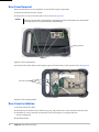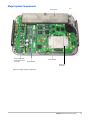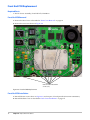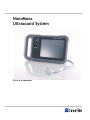
1
NanoMaxx
Ultrasound System
Service Manual
SonoSite, Inc.
21919 30th Drive SE
Bothell, WA 98021-3904
USA
Telephone: 1-888-482-9449 or 1-425-951-1200
Fax: 1-425-951-1201
SonoSite Ltd
Alexander House
40A Wilbury Way
Hitchin, Herts
SG4 OAP UK
T: +44-1462-444800
F: +44-1462-444801
Caution:
Federal (United States) law restricts this device to sale by or on the order of a physician.
NanoMaxx, SiteLink, SonoSite, and the SonoSite logo are registered trademarks or trademarks of SonoSite, Inc.
DICOM is the registered trademark of the National Electrical Manufacturers Association for its standards publications relating to digital communications
of medical information.
The SonoSite ultrasound system(s) referenced in this document may be covered by one or more of the following U.S. patents: 5722412, 5817024, 5893363,
6135961, 6203498, 6364839, 6371918, 6383139, 6416475, 6447451, 6471651, 6569101, 6648826, 6575908, 6604630, 6817982, 6835177, 6962566,
7169108, 7449640, 7534211, 7549961, 7588541, 7591786, 7604596, 7643040, D456509, D461895, D509900, D538432, D544962, D558351, D559390,
D591423, D592750, D592760, and by the following counterpart foreign patents: AU727381, AU730822, CA2372158, CA2373065, CN ZL 97113678.5, CN
ZL 98106133.8, CN ZL 98108973.9, CN ZL 200830007734.8, DE60021552.0, DE60029777.2, DE60034670.6, DE69730563.5, DE6980539.6, DE69831698.3,
DE60 2004 23 816.3-08, FR0815793, FR0875203, FR0881492, FR1175713, FR1180970, FR1589878, GB0875203, GB0881492, GB1175713, GB1180970,
GB1180971, GB1589878, IT0815793, IT0881492, IT1175713, IT1589878, KR528102, KR532359, NO326202, NO326814, NZ542968, RCD000897368-0001,
SP0815793, SP0881492, SP1589878. Patents pending
P12706-01 04/2010
Copyright 2010 by SonoSite, Inc.
All rights reserved.
ii
Contents
Chapter 1 - Introduction
Audience.............................................................................................................................. 1
Conventions ........................................................................................................................ 1
Contact Information........................................................................................................... 1
Chapter 2 - System Overview
About the System ............................................................................................................... 3
Theory of Operation........................................................................................................... 3
System Specifications......................................................................................................... 6
Chapter 3- Troubleshooting
Periodic Maintenance ........................................................................................................ 11
Technical Bulletins ............................................................................................................. 11
System and Subsystem Diagnosis.................................................................................... 11
System Repair ..................................................................................................................... 11
Test Equipment................................................................................................................... 11
Failure (Assert) Codes ....................................................................................................... 12
Chapter 4- Replacement Procedures
Required Tools.................................................................................................................... 13
Rear Cover Removal .......................................................................................................... 14
Rear Cover Installation ...................................................................................................... 14
Major System Components ............................................................................................... 15
Front End PCB Replacement ............................................................................................ 16
Power Supply PCB Replacement ..................................................................................... 17
Back End PCB Replacement.............................................................................................. 18
Other Major System Components.................................................................................... 19
User Interface PCB Replacement ..................................................................................... 20
Display Backlight Inverter (BLI) PCB Replacement...................................................... 21
LCD Replacement............................................................................................................... 22
Chapter 5- Performance Testing
Overview ............................................................................................................................. 25
Test Equipment................................................................................................................... 25
Set Up Performance Tests ................................................................................................. 25
Basic Operational Tests...................................................................................................... 25
2D Performance Tests ........................................................................................................ 26
Additional Performance Tests .......................................................................................... 27
iii
Appendix A - Replacement Parts List
Major System Components ............................................................................................... 29
Other System Components ............................................................................................... 30
Miscellaneous System Components ................................................................................ 31
Ordering Replacement Parts............................................................................................. 31
Appendix B - Service Event Reporting
Service Event Report Form ............................................................................................... 34
Service Event Report Instructions.................................................................................... 35
Returning Products to SonoSite ....................................................................................... 36
iv
Chapter 1: Introduction
Before servicing the NanoMaxx ultrasound system, please read this manual.
The ultrasound system has multiple configurations and feature sets. All are described in this service manual but not every option may apply to your system. System features depend on your system configuration, transducer, and exam type.
Refer to the NanoMaxx Ultrasound System User Guide for additional information regarding safety, system controls, operation, capabilities, and specifications.
Audience
The intended audience of this manual is properly trained field and in‐house service personnel.
Conventions
These conventions are used in this service manual:
• A WARNING describes precautions necessary to prevent injury or loss of life.
• A Caution describes precautions necessary to protect the products.
• Numbered steps must be performed in a specific order.
• Bulleted lists present information in list format but do not imply a sequence.
• Labeling symbols are in the user guide.
Contact Information
Questions and comments are encouraged. SonoSite is interested in your feedback regarding the service manual. If you encounter difficulty with the system, use the information in this manual to help correct the problem. If the problem is not covered here, contact SonoSite Technical Support as follows: Technical Support (USA, Canada) phone:
1-877-657-8118
Technical Support fax:
1-425-951-6700
Technical Support e-mail:
[email protected]
SonoSite Web site:
www.sonosite.com>Support
International Technical Support:
Contact your local representative or call (USA)
+425-951-1330
European Service Center:
+44-(0)1462-444-800
e-mail: [email protected]
Japan Service Center:
+81-3-5304-5337
e-mail: [email protected]
Chapter 1: Introduction
1
2
Chapter 1: Introduction
Chapter 2: System Overview
About the System
The SonoSite NanoMaxx high‐resolution ultrasound system is a portable, software controlled, diagnostic ultrasound system using all digital architecture. The system is used to acquire and display high‐resolution, real‐time ultrasound data in 2D, Color Power Doppler (CPD), and Color Doppler (Color) or in a combination of these modes.
The system provides measurement capabilities for anatomical structures and fetal biometry that provide information used for clinical diagnostic purposes. System features include cine review, image zoom, labeling, needle guidance, measurements, calculations, and image storage/review/printing/recording capabilities.
The system/transducer is capable of exceeding a TI or an MI of 1.0 in certain operating modes or mode combinations. The system displays the current output level in terms of one of two bioeffects indices (“Mechanical Index [MI]” and “Thermal Index [TI]”) in accordance with the AIUM/NEMA Standard for Real Time Display of Thermal and Mechanical Acoustic Output Indices on Diagnostic Ultrasound Equipment.
Theory of Operation
The NanoMaxx ultrasound system has seven (7) major functional groups: • Transducer
• Acquisition Subsystem
• Processing Subsystem
• Display Subsystem
• Control Subsystem
• User Interface Subsystem
• Power Subsystem
Figure 2.1 shows the relationship of the functional groups.
Chapter 2: System Overview
3
Figure 2.1 SonoSite High-Resolution Ultrasound System (NanoMaxx) Block Diagram
The Transducer elements convert the pulser voltage to acoustic energy during the transmit portion of the ultrasound acquisition cycle. The elements convert the acoustic echo to voltage in the receive portion of the acquisition. The voltage developed on the transducer elements is sensed by the acquisition subsystem. The system transducers have 64 to 192 elements depending on transducer selected. The Acquisition Subsystem consists of the beamformer and interface to the transducer. The beamformer controls the timing of the transmit pulses to focus the acoustic beam. The beamformer amplifies the low‐level received echoes and controls the receive focusing. The system beamformer transmits on up to 128 elements and receives on 64 elements.
The Processing Subsystem includes capabilities for interfacing with the beamformer and performing high speed processing. The processing subsystem demodulates, filters, detects, and compresses the signal supplied by the beamformer into display information.
The Display Subsystem converts the detected ultrasound data into picture elements (pixels). The software user interface graphics are combined with the ultrasound information and converted to a video stream. The external video port supports NTSC and PAL format.
The Control Subsystem consists of the central processing unit, program and video memory, permanent image storage and retrieval memory, external communication interface ports, and connection to the user interface keys. The control software includes the acoustic power and intensity software subsystem, power group monitors, and a beamformer monitor. This software guarantees a level of patient safety by ensuring the system is operating within acoustic power and intensity limits. The User Interface Subsystem represents the software interface and form factor. The software interface is the interaction between the user and the screen layout components. The form factor is the type of physical buttons, location, and grouping of the buttons and the device size, shape, and weight. Dedicated controls are for high usage activities and grouped according to the user workflow.
The Power Subsystem provides the system power and protects the hardware from destructive and/or unsafe conditions by detecting failures in the system through hardware and software monitors. Detection of a fault results in disabling of the pulser supply, and the signaling of an error to the Control Group. The power subsystem includes the battery pack and battery charging electronics.
4
Chapter 2: System Overview
Description of Operating Modes
2D Mode
2D mode is a two dimensional image of the amplitude of the echo signals. It is used for location and measurement of anatomical structures and for spatial orientation during operation of other modes. In 2D, a two‐dimensional cross‐section of a 3‐dimensional soft tissue structure such as the heart is displayed in real time. Ultrasound echoes of different intensities are mapped to different gray scale or color values in the display. The outline of the 2D cross‐section may be a rectangle, parallelogram, trapezoid, sector, or a full circle, depending on the particular transducer used. 2D mode can be used in combination with any other modes.
Color
Doppler
(Color)
In Color Doppler, a real‐time, two‐dimensional cross‐section of blood flow is displayed. The 2D cross‐section may be presented as a rectangle, parallelogram, trapezoid, sector, or a full circle, depending on the particular transducer used.
The 2D cross‐section is presented as a full color display, with various colors being used to represent the velocity, both positive and negative, of the blood flow echoes. Often, to provide spatial orientation, the full color blood flow cross‐section is overlaid on top of the gray scale cross‐section of soft tissue structure (2D echo). For each pixel in the overlay, the decision of whether to display color, gray scale (echo) information or a blended combination is based on the relative strength of echoes from the soft‐tissue structures and from the red blood cells.
A high pass filter (wall filter) is used to remove the signals from stationary or slowly moving structures. Tissue motion is discriminated from blood flow by assuming that blood is moving faster than the surrounding tissue, although additional parameters may also be used to enhance the discrimination. The remaining signal after wall filtering may be averaged over time (persistence) to present a steady state image of blood flow distribution. Variance information may also be displayed to provide information when large variance is observed in the velocity information.
Color Power
Doppler
(CPD)
In CPD, a real‐time two‐dimensional cross‐section of blood flow is displayed. The 2D cross‐section may be presented as a rectangle, parallelogram, trapezoid, sector, or a full circle, depending on the particular transducer used. The 2D cross‐section is presented as a full color display, with various colors being used to represent the power in blood flow echoes. Often, to provide spatial orientation, the full color blood flow cross‐section is overlaid on top of the gray scale cross‐section of soft tissue structure (2D echo). For each pixel in the overlay, the decision of whether to display CPD, gray scale (echo) information or a blended combination is based on the relative strength of echoes from the soft‐tissue structures and from the red blood cells.
A high pass filter (wall filter) is used to remove the signals from stationary or slowly moving structures. Tissue motion is discriminated from blood flow by assuming that blood is moving faster than the surrounding tissue, although additional parameters may also be used to enhance the discrimination. The power in the remaining signal after wall filtering may be averaged over time (persistence) to present a steady state image of blood flow distribution.
Chapter 2: System Overview
5
Additional System Feature Performances
Broadband
Imaging
This ultrasound acquisition system uses high resolution broadband technology in the transmit pulsers, transducers, and receivers. The receive path can capture and process signals over a wide spectrum from below 2.0 MHz to beyond 10 MHz. For each application the transmit pulse is designed to produce an appropriate bandwidth. For example, in 2D grayscale imaging, a wide band pulse is used to support good axial resolution. For Doppler modes a narrower band pulse is used which improves the spectral resolution of the detected Doppler signal.
In addition to transmit pulse control, programmable digital signal processing is used in the receive path to further refine the bandwidth used to produce the final image. Digital filters are applied to the digitized received signal to limit and shape the spectral bandwidth used to generate the displayed output.
Needle
Guidance
The system can display a pair of needle guidelines that represent the anticipated path of the needle. The image of the anatomical target, needle guidelines, and a scan plane marker are displayed to assist in guiding the needle to the target. For additional information, see the needle user guides.
Measurement
and
Calculation
Capabilities
The system offers a variety of measurements and calculations specific to exam type and transducer. A list of them, and author references, are in the system user guide. Measurement accuracy is also discussed.
System Specifications
This section contains system and accessory specifications and agency approvals. The specifications for recommended peripherals can be found in the manufacturers’ instructions. See the applicable SonoSite accessory user guide for information on the accessories.
System Dimensions
Height: 8.2in. (20.8 cm)
Width: 14.1 in. (35.8 cm)
Depth: 2.3in. (5.8 cm)
Weight: 6 lbs. (2.72 kg)
Display Dimensions
Length: 8.4 in. (21.34 cm)
Height: 6.3 in. (16 cm)
Diagonal: 10.4 in. (26.4 cm)
Transducers
Note: Each of the NanoMaxx system types (S‐ICU, S‐Nerve, etc.) supports a unique combination of transducers. C11n/8‐5 MHz 11 mm curved array (6 ft./1.8 m)
C60n/5‐2 MHz 60 mm curved array (5.5 ft./1.7 m)
L25n/13‐6 MHz 25 mm linear array (7.5 ft./2.3 m)
L38n/10‐5 MHz 38 mm linear array (5.5 ft./1.7 m)
P21n/5‐1 MHz 21 mm phased array (6 ft./1.8 m)
6
Chapter 2: System Overview
Imaging Modes
2D (256 gray shades)
Color power Doppler (CPD) (256 colors)
Color Doppler (Color) (256 colors)
Image and Clip Storage
The number of images and clips you can save varies with imaging mode and file format. The internal storage can save approximately 40 patients with 50 images each.
Accessories
Hardware, Software, and Documentation
Battery
Carry Case
Kensington Security Cable
Needle Guides (L25n only)
Power supply
SonoCalc IMT Software 4.1
V‐Universal Stand
System User Guide (CD Standard/Hardcopy optional)
System AC PowerCcord (10 ft / 3.1 m)
VESA Compliant Mounting
Video and printer cables
Cables
See the NanoMaxx Ultrasound System User Guide or the V‐Universal Stand User Guide for information on cables.
Peripherals
Peripherals include the following medical grade (conforming to the requirements of EN60601‐1) and non‐medical grade (commercial) products. Manufacturer’s instructions accompany each peripheral. System setup instructions are in the NanoMaxx Ultrasound System User Guide. Instructions for using peripherals with the system are in the applicable SonoSite accessory user guide.
Medical Grade
Black‐and‐white printer
Non-Medical Grade
2GB USB Memory Stick
Chapter 2: System Overview
7
Temperature, Pressure, and Humidity Limits
Note: The temperature, pressure, and humidity limits apply only to the ultrasound system and transducers.
Operating Limits: System, battery, and transducer
• 10–40°C (50–104°F), 15–95% R.H.
• 700 to 1060hPa (0.7 to 1.05 ATM)
Shipping/Storage Limits: System and transducer
• ‐35–65°C (‐31–149°F), 15–95% R.H.
• 500 to 1060hPa (0.5 to 1.05 ATM)
Shipping/Storage Limits: Battery
• ‐20–60°C (‐4–140°F), 0–95% R.H. (For storage longer than 30 days, store at or below room temperature.)
• 500 to 1060hPa (0.5 to 1.05 ATM)
Electrical
Power Supply Input: 100‐240 VAC, 50/60 Hz, 2.0 A Max @ 100 VAC.
Power Supply Output 1:
15 VDC, 5.0A Max (system)
Power Supply Output 2:
12 VDC, 2.3A Max (battery)
Combined output not exceeding 75W.
Battery
6‐cell, 11.2 VDC, 5.2 amp‐hours, rechargeable lithium ion battery pack.
Run time is up to 2 hours, depending on imaging mode and display brightness.
Electromechanical Safety Standards
EN 60601‐1:1997, European Norm, Medical Electrical Equipment–Part 1. General Requirements for Safety.
EN 60601‐1‐1:2001, European Norm, Medical Electrical Equipment–Part 1. General Requirements for Safety–Section 1‐1. Collateral Standard. Safety Requirements for Medical Electrical Systems.
EN 60601‐1‐2:2001, European Norm, Medical Electrical Equipment – Part 1‐2: General Requirements for Safety ‐ Collateral Standard: Electromagnetic compatibility ‐ Requirements and tests
EN 60601‐2‐37:2001 + Amendment A1:2005, European Norm, Particular requirements for the safety of ultrasonic medical diagnostic and monitoring equipment.
CAN/CSA C22.2, No. 601.1‐M90, Canadian Standards Association, Medical ElectricalEquipment.Part 1. General Requirements for Safety (including CSA 601.1 Supplement 1:1994 and CSA 601.1 Amendment 2:1998)
CEI/IEC 61157:1992, International Electrotechnical Commission, Requirements for the Declaration of the Acoustic Output of Medical Diagnostic Ultrasonic Equipment.
UL 60601‐1 (1st Edition), Underwriters Laboratories, Medical Electrical Equipment ‐ Part 1: General Requirements for Safety.
8
Chapter 2: System Overview
EMC Standards Classification
EN 60601‐1‐2:2001, European Norm, Medical Electrical Equipment. General Requirements for Safety‐Collateral Standard. Electromagnetic Compatibility. Requirements and Tests.
CISPR11:2004, International Electrotechnical Commission, International Special Committee on Radio Interference. Industrial, Scientific, and Medical (ISM) Radio‐Frequency Equipment Electromagnetic Disturbance Characteristics‐Limits and Methods of Measurement.
The Classification for the SonoSite system, V Universal Stand, accessories, and peripherals when configured together is: Group 1, Class A.
Airborne Equipment Standards
RTCA/DO‐160E:2004, Radio Technical Commission for Aeronautics, Environmental Conditions and Test Procedures for Airborne Equipment, Section 21.0 Emission of Radio Frequency Energy, Category B.
DICOM Standard
NEMA PS 3.15: 2000, Digital Imaging and Communications in Medicine (DICOM)‐Part 15: Security Profiles.
HIPAA Standard
The Health Insurance and Portability and Accountability Act, Pub.L. No. 104‐191 (1996).
45 CFR 160, General Administrative Requirements.
45 CFR 164, Security and Privacy.
Chapter 2: System Overview
9
10
Chapter 2: System Overview
Chapter 3: Troubleshooting
This chapter contains information to help you correct problems with system operation and provides instructions on the proper care of the system, transducer, and accessories.
Periodic Maintenance
There is no recommended periodic or preventive maintenance required for the system, transducers, or accessories. There are no internal adjustments or alignments required. There are no functions that require periodic testing or calibration. Performance tests are described in Chapter 5, “Performance Testing,” of this manual. Performing maintenance activities not described in this manual may void the product warranty.
Local regulations may require electrical safety testing.
Contact SonoSite Technical Support for any maintenance questions.
Technical Bulletins
Product Technical Bulletins describing known system issues are periodically placed on SonoSite.com. Select Support and then follow the links to NanoMaxx Support Documents. System and Subsystem Diagnosis
This section covers basic diagnostic and troubleshooting procedures you may follow if the system does not operate properly. To diagnose system failures, consult the referenced diagnostic figures that follow or call SonoSite Technical Support.
Table 3.1: Troubleshooting Subassemblies and Diagnostic Figures
Subassemblies
Diagnostic Figures or Table
Display
TBA
Battery
TBA
Control Panel
TBA
System Repair
The system is repairable through subassembly replacement or through replacement of parts as recommended by SonoSite in Chapter 4, “Replacement Procedures.” Component level repair of Printed Circuit Board Assemblies is performed only at the SonoSite repair facility. Replacement of board level components by unauthorized service facilities voids the SonoSite warranty.
Test Equipment
Test equipment is not required for this troubleshooting section. Troubleshooting test aids include an external monitor and a spare battery.
Chapter 3: Troubleshooting
11
Failure (Assert) Codes
ʺAssertʺ or ʺAssert Codeʺ are software error codes that are generated by all Sonosite products when certain hardware or software fault conditions exist. Providing the Assert Code to the Technical Support Group may assist in quicker and more accurate fault diagnosis. Hardware Assert Codes typically cannot be reset and will usually require Main PCB replacement. Many software Assert Codes can be reset and the system may recover and operate normally, usually requiring a reboot. Handling Assert Codes
1 Record the Assert Code. The Assert Code is a four or five digit number shown on the C: line of the Maintenance Screen. A typical Maintenance Screen with an Assert Code is shown in Figure 3.1.
Assert Code
Figure 3.1 Maintenance Screen with Assert Code
2 Press and release the Power button to power the system down. It may be necessary to hold down the Power button as long as 10 seconds in some cases.
3 Press the Power button again to power the system up.
• If the system powers up normally, it has recovered from the fault (software assert) and you may use the system.
• If the Assert Code remains, corrective action must be taken; usually replacement of the the Back End PCB is required. Contact SonoSite Technical Support for assistance and to obtain repair parts.
If the Power button is not functional, all sources of power must be removed to allow the system to power down. i.e., disconnect AC power and remove the battery.
12
Chapter 3: Troubleshooting
Chapter 4: Replacement Procedures
Caution:
Always use correct ESD procedures. ESD damage is cumulative and may not be noticeable at first.
Initial ESD symptoms may be slightly degraded performance or image quality.
Required Tools
• #1 and #2 Phillips screwdrivers
• #1 and #2 Flat Blade screwdrivers
• 3 mm Allen Key
• 3/16” Nut Driver or equivalent wrench/socket
• Kapton tape
• Torque screwdriver, 2.0–10.0 inch pounds (23–110 newton‐centimeters)
• Cotton swabs (Q Tips)
• Anti‐static mat & wrist grounding strap
Chapter 4: Replacement Procedures
13
Rear Cover Removal
Removal of the Rear Cover is required to access all other system components.
1 Remove the battery from the system.
2 Remove the six screws from the Rear Cover as shown in Figure 4.1
Caution:
There are several cables connecting the top and bottom halves of the system. Use caution when
removing the rear cover to prevent cable or PCB damage.
Battery removed
Screws (6x)
Figure 4.1 Rear Cover Removal
3 Disconnect the three cables connecting the upper and lower halves of the system as show in Figure 4.2 Disconnect cables
Figure 4.2 Disconnecting Cables
Rear Cover Installation
1 Reconnect the three cables.
2 Insert the top of the Rear Cover under the top cap, and press down to mate with the Front Enclosure. 3 Install the six screws removed from the Rear Cover and torque to 5.5 inch/pounds (62 newton‐centimeters). 4 Install the battery.
14
Chapter 4: Replacement Procedures
Major System Components
Fan
Battery Well
Power Supply PCB
(shown with shield
removed)
Front End PCB
Back End PCB
Nest Frame
Assembly
Figure 4.3 Major System Components
Chapter 4: Replacement Procedures
15
Front End PCB Replacement
Required Parts
• P12717 Service Assembly, Front End PCB, NanoMaxx
Front End PCB Removal
1 Remove the Rear Cover as described in “Rear Cover Removal” on page 14.
2 Remove the ten screws shown in Figure 4.4.
Remove P09037 M3.5x6mm
screws (10x).
Figure 4.4 Front End PCB Replacement
Front End PCB Installation
1 Reinstall the ten screws shown in Figure 4.4, and torque to 5.5 inch/pounds (62 newton‐centimeters).
2 Reinstall the Rear Cover as described in “Rear Cover Installation” on page 14.
16
Chapter 4: Replacement Procedures
Power Supply PCB Replacement
Required Parts
• P12745 Service Assembly, Power Supply, M‐Turbo / NanoMaxx
Power Supply PCB Removal
1 Remove the Rear Cover as described in “Rear Cover Removal” on page 14.
2 Remove the upper Power Supply Shield (not shown) by removing the 4 screws. 3 Remove the hex standoffs (x4) as shown in Figure 4.5.
4 Remove the screw as shown in Figure 4.5.
5 Remove the Power Supply PCB.
P09037 M3.5x6mm screw
P10273 Hex Standoff
M3 - .5x10 (4x)
Figure 4.5 Power Supply PCB Replacement
Power Supply PCB Installation
1 Ensure the Lower Power Supply Shield is properly installed under the Power Supply mounting location.
2 Place the replacement Power Supply PCB onto the Front End PCB. 3 Reinstall the one screw and the four hex standoffs in the locations shown in Figure 4.5 and torque all fasteners to 5.5 inch/pounds (62 newton‐centimeters).
4 Reinstall the Upper Power Supply shield and torque the shield fasteners to 5.5 inch/pounds (62 newton‐centimeters).
Chapter 4: Replacement Procedures
17
Back End PCB Replacement
Required Parts
• P12718 Service Assembly, Back End, M‐Turbo / NanoMaxx
Back End PCB Removal
1 Remove the Rear Cover as described in “Rear Cover Removal” on page 14.
2 Remove the Front End PCB as described in“Front End PCB Removal” on page 16.
3 Remove the Power Supply PCB as described in “Power Supply PCB Removal” on page 17.
4 Disconnect the Fan cable from the Back End PCB as shown in Figure 4.6.
5 Remove the eight screws as shown in Figure 4.6.
6 Remove the SD Card from the holder for use with the replacement PCB.
Fan Cable Connector
P09037 M3.5x6mm screws (8x)
Figure 4.6 Back End PCB Replacement
Back End PCB Installation
1 Install the SD card (removed from old PCB) into the replacement Back End PCB.
2 Install the replacement Back End PCB into the frame.
3 Install the eight screws and torque the screws to 5.5 inch/pounds (62 newton‐centimeters).
Caution:
Inspect the Power Supply Shield to ensure that none of the contacts are bent. Improper contact between the shield and the Power Supply Frame can cause image noise problems.
4 Reconnect the fan cable to the Back End PCB as shown in Figure 4.6.
5 Reinstall the Front End PCB as described in “Front End PCB Installation” on page 16.
6 Reinstall the Power Supply PCB as described in “Power Supply PCB Installation” on page 17.
7 Reinstall the Rear Cover as described in.“Rear Cover Installation” on page 14.
18
Chapter 4: Replacement Procedures
Other Major System Components
LCD Touchscreen Cable
Display Cable
Backlight Inverter PCB
User Interface PCB
FFC 6” Cable Assy
Backlight Inverter
Shield
LCD Housing
Figure 4.7 Other Major System Components
Chapter 4: Replacement Procedures
19
User Interface PCB Replacement
Required Parts
• P12329 User Interface PCB, NanoMaxx
User Interface PCB Removal
1 Remove the Rear Cover as described in “Rear Cover Removal” on page 14.
2 Remove the knob from the front of the system.
3 Disconnect the LCD touchscreen ribbon cable from the User Interface PCB as shown in Figure 4.8.
4 Remove the five screws shown in Figure 4.8.
Caution:
The FFC ribbon cable connector is fragile and will require replacement of the User Interface PCB if
damaged.
5 Disconnect the FFC ribbon cable by gently lifting up on the connector latch as shown in Figure 4.8.
LCD Touchscreen ribbon cable
FFC ribbon
cable
Figure 4.8 User Interface PCB Replaclement
User Interface PCB Installation
1 Reinstall the FFC ribbon cable onto the replacement User Interface PCB as shown in Figure 4.8. Ensure the cable is fully seated into the connector and reengage the connector latch.
2 Install the replacement User Interface PCB onto the front enclosure as shown Figure 4.8.
3 Reinstall the five screws and torque the screws to 5.5 inch/pounds (62 newton‐centimeters).
4 Reconnect the LCD Touchscreen ribbon cable ensuring the cable is looped as shown in Figure 4.7.
5 Reinstall the knob on the front enclosure.
6 Reinstall the Rear Cover as described in “Rear Cover Installation” on page 14.
20
Chapter 4: Replacement Procedures
Display Backlight Inverter (BLI) PCB Replacement
Required Parts
• P09195 Display Backlight Inverter PCB
• P09199 Backlight Inverter Wire Harness (optional)
Display Backlight Inverter PCB Removal
1 Remove the Rear Cover as described in “Rear Cover Removal” on page 14.
2 Remove the two screws from the Backlight Shield Cover and set the shield aside.
3 Disconnect the LCD wire harness connecting the Backlight Inverter PCB and the LCD as shown in Figure 4.9
4 Carefully remove the Backlight Inverter PCB from the enclosure.
5 Disconnect the BLI Power Harness from the Backlight Inverter PCB and set aside.
LCD Wire
Harness
BLI Power
Harness
(P09199)
BLI Shield Cover
(P09855)
BLI Power Harness routed
through shield vent holes
Figure 4.9 Backlight Inverter Replacment
Display Backlight Inverter PCB Installation
1 Reconnect the BLI Power Harness to the replacement Backlight Inverter PCB.
2 Reconnect the LCD wire harness to the replacement Backlight Inverter PCB.
3 Insert the replacement Backlight Inverter PCB into the on the LCD Housing as shown in Figure 4.9.
4 Route the BLI Power Harness through the enclosure vent holes as shown in Figure 4.9.
5 Reinstall the Backlight Inverter Shield Cover and two mounting screws. Torque the screws to 5.5 inch/pounds (62 newton‐centimeters). 6 Reinstall the Rear Cover as described in “Rear Cover Installation” on page 14.
Chapter 4: Replacement Procedures
21
LCD Replacement
Required Parts
• P09732 LCD, 8.4”. This part number is for the LCD monitor only. Cables and mounting hardware are not included.
• P09200 Display Wire Harness (optional)
LCD Removal
1 Remove the Rear Cover as described in “Rear Cover Removal” on page 14.
2 Disconnect the LCD Power Wire Harness from the Display Backlight Inverter PCB as shown in Figure 4.10.
3 Disconnect the Touchscreen cable from the User Interface PCB as shown in Figure 4.10.
4 Remove the four LCD frame mounting screws shown in Figure 4.10. 5 Remove the LCD mounting frame from the front enclosure.
6 Remove the Display Cable connected to the LCD. Disconnect LCD
Power Wire
Harness
Disconnect LCD
Touchscreen
cable
Display Cable
(P09200)
LCD Mounting
Screws (4x)
Figure 4.10 LCD Removal
22
Chapter 4: Replacement Procedures
LCD Installation
Caution:
Use extreme caution when installing the Display Cable to prevent irreparable damage to the LCD.
1 Connect the Display Cable to the LCD as shown in Figure 4.11A. Apply a piece of Kapton tape to the connector and LCD housing to aid in cable retention.
2 Insert the replacement LCD into the Display Housing loosely routing the cables as shown in Figure 4.11B.
3 Route the Display Cable under the display housing as shown in Figure 4.11C. Be careful not to disengage the cable from the LCD connector as shown in Figure 4.11A.
4 Insert the Display Housing with LCD into the front enclosure and loosely install the four mounting screws as shown in Figure 4.10 on page 22. 5 Check proper routing of cables to prevent damage.
6 Observe the position of the LCD from the front of the enclosure and adjust the position as necessary to center the LCD in the opening. 7 Tighten the four mounting screws to 5.5 inch/pounds (62 newton‐centimeters).
Kapton tape
B. Cable Routing
A. Kapton tape
C. Cable Routing
Figure 4.11 LCD Installation
8 Reconnect the LCD Power Wire Harness and dress the cable as shown in Figure 4.10 on page 22.
9 Reinstall the Rear Cover as described in “Rear Cover Installation” on page 14.
Chapter 4: Replacement Procedures
23
24
Chapter 4: Replacement Procedures
Chapter 5: Performance Testing
Overview
WARNING:
Critical Test Function — A failure of the system functions tested in this section could adversely
affect the safety or effectiveness of the system. While performing the steps in this section, verify
that the images on the system display and on the external monitor are acceptable.
To obtain 2D images, SonoSite recommends using the RMI 413A Soft Tissue Phantom or the RMI 403 GS Multipurpose Phantom. A .7db/cm phantom is required for performing penetration measurements. Any equivalent .7db/cm Phantom is acceptable.
When making penetration measurements on a phantom, apply the phantom reference value and tolerance to the measurement.
Some features and capabilities are optional and therefore may be unavailable to test.
Test Equipment
• SonoSite ultrasound system under test
• Transducer compatible with the system under test
• RMI 413A Soft Tissue Phantom, RMI 403 GS Multipurpose Phantom, or equivalent. A referenced.7db/cm phantom is required for performing penetration measurements.
• Video printer recommended
• Acoustic gel
Set Up Performance Tests
Set Up Performance Tests
1 Attach a compatible transducer to the system under test.
2 Select Gen for optimization type.
3 Couple the transducer to the phantom, adjusting gain settings and transducer for a proper phantom image (e.g., pins are high‐level echoes positioned in straight lines; cysts are sonolucent, edges are sharp, and graphite particles of the phantom are mid‐grays).
Basic Operational Tests
Basic System Operation Tests
1 Verify that the correct transducer name appears in the upper right corner of the system display.
2 Verify proper date and time.
3 Verify that the scan plane orientation mark in the image located near the skinline corresponds to element #1 on the transducer. To test, put your finger on the probe and run it across the transducer face. Your finger touching the transducer face should appear at the orientation mark on the display image format.
4 Verify that all controls and buttons smoothly over their full range and that the system responds properly.
5 Verify that all of the softkeys are functional. 6 Verify that as the Gain controls are increased and decreased, there is a corresponding increase and decrease in echo intensity.
Chapter 5: Performance Testing
25
2D Performance Tests
2D Performance / Image Quality
Test 2D Performance and Image Quality
1 Adjust the position of the transducer on the phantom to acquire a good phantom image as described in the “Set Up Performance Tests” section.
2 With the array pointing down and the orientation mark to the operator’s left, element #1 corresponds with the left side of the array.
3 Use the 2D system controls to obtain a clear image that shows both the horizontal and vertical rows of pins.
4 Verify that the ultrasound image appears uniform in both the axial and lateral direction, with no dropouts or intensity variations.
5 Verify that the cystic structure at the focal zone is clearly differentiated from the surrounding tissue and is echo‐free, while solid tissue with numerous echo sources appears solid.
6 Press the Freeze key and then save the image. Press the Freeze key again to return to live imaging.
Axial Measurement Accuracy
Note: Measurements must be performed while the image is frozen.
Set Up Axial Measurement Accuracy
1 Acquire a phantom image of the target pins as described above.
2 Press the Freeze key.
3 Press the Calipers key. The caliper appears. (See the NanoMaxx Ultrasound System User Guide, if necessary, for caliper operation.)
4 Use the Knob and Up/Down ‐ Left/Right buttons to position the first end of the caliper.
5 Press the Select button to enable the other end of the caliper.
6 Use the Knob and Up/Down ‐ Left/Right buttons to position the second end of the caliper. The results update as you move the caliper, and the measurement is complete when you finish moving the calipers. Test Axial Measurement Accuracy
1 Measure the distance, center to center, of any two pins that are 5‐12 cm apart vertically.
2 Verify that the distance measured is within the tolerance listed in Table 1 on page 27.
26
Chapter 5: Performance Testing
Lateral Measurement Accuracy
Set Up Lateral Measurement Accuracy
Perform “Set Up Axial Measurement Accuracy” on page 26.
Test Lateral Measurement Accuracy
1 Measure the distance, center to center, of any two pins that are 4‐10 cm apart horizontally.
2 Verify that the distance measured is within the tolerance listed in Table 1.
3 Press the Freeze key to return the system to live 2D mode.
Table 1: System Measurement Accuracy
Measurements
Tolerance
Axial Distance
+/- 2%
Lateral Distance
+/- 2%
Penetration
TBD
Additional Performance Tests
Color Doppler (Color)
Test Color
1 Connect any transducer.
2 Press the Color key. 3 A Region of Interest (ROI) box is displayed on top of the grayscale image. Use the touchscreen to move the CPD ROI. Verify that the ROI moves to the new position on the display.
4 Adjust the Depth control for minimum depth in the image.
5 Adjust the Gain control so that color speckles just appear inside the ROI box.
6 Gently tap the face of the transducer and observe that the ROI box fills with color information.
7 Press the Freeze key and then save the image. 8 Press the Freeze key again to return to live imaging.
Color Power Doppler (CPD)
Test CPD
1 Connect any transducer.
2 Press the Color key. A ROI box appears on top of the grayscale image.
3 Press the Color key on the left side of the display to switch to CPD. “CPD” should be annotated on the Color/CPD key.
4 Adjust the Depth control for minimum depth in the image.
5 Adjust the Gain control so that color speckles appear just inside the ROI box.
6 Gently tap the face of the transducer, and observe that the ROI box fills with color information.
Chapter 5: Performance Testing
27
Image Quality Verification Test/Livescan
• Products with replaced subassemblies, or products that have been otherwise disassembled, should undergo an Image Quality Verification Test/Livescan.
• The Image Quality Verification Test/Livescan should be performed after successfully completing all applicable performance tests listed above.
• The test is completed before returning the system to operation.
• It is recommended that a certified sonographer perform the image quality verification.
• The Livescan test performed is at the discretion of the sonographer and will represent their acceptance of a successful service event.
• Review all saved images and verify that the images are displayed properly.
Printer
Test Printer Operation (Optional)
1 Verify proper printer type is configured.
2 Press the print button and verify that the printer begins to print an image. After the image begins to emerge from the printer, press the print button again. The printer should ignore the second print command.
3 Verify the proper content of the printed image.
Battery Charging
Test Battery Charging Operation
1 Insert a battery into the system and remove the power cord from the NanoMaxx dock.
2 Press the power key to turn the system on. 3 Allow the battery to discharge. The battery indicator icon on the display, below the Transducer Type indicator, extinguishes from right to left as the battery discharges. Note: The Power and Sleep delay settings in the Audio, Battery setup page should be selected to Off to properly perform this test. The battery may take 1–2 hours to discharge.
4 Attach the AC power cord to the power connector. Press the power key to turn the system on. 5 Note that the battery indicator indicates that the battery is charging. The sections of the battery indicator will light sequentially from left to right as the battery charges.
Video Output
Caution:
Use only the recommended video monitor or printer when verifying the video output at the
video receptacle.
Test Video Output (Optional)
1 Attach an external video monitor to the video connector using the video cable.
2 Turn on the system power and verify that the video on the external monitor matches the video on the system display.
If the video does not appear similar, or there is no display on the external monitor, see Chapter 3, “Troubleshooting” for troubleshooting procedures.
28
Chapter 5: Performance Testing
Appendix A: Replacement Parts List
The following tables contain all the field‐replaceable parts for the NanoMaxx ultrasound system. Quantities are one unless otherwise noted.
Major System Components
5
1
3
2
4
Table 1: Major System Components
Item Number
Part Number
Description
1
P12745
Power Supply PCB Service Assembly (Shown without shields)
Not shown
P09866
Shield, Digital Bottom (Bottom Power Supply Shield)
Not shown
P09867
Shield, Digital Top (Top Power Supply Shield)
2
P12718
Back End PCB Service Assembly
3
P12717
Front End PCB Service Assembly
4
P09196
Fan/Cable
5
P13068
Service Assembly, NanoMaxx Rear Enclosure (Enclosure only - does not contain
any of the parts listed above)
Appendix A: Replacement Parts List
29
Other System Components
7
1
2
11
4
3
10
5
9
6
8
Table 2: Other System Components
30
Item Number
Part Number
Description
1
P09200
Display Cable Assy
2
-
Part of LCD Assembly
3
P09195
Backlight Inverter PCB
4
P09199
BLI Power Harness (Inverter Cable Assy)
5
P09895
Backlight Inverter Cover (Shown partially removed)
6
P08398
Display Isolation Damper Shoulder Screw (4x)
7
P07477
Display Isolation Damper (4x)
8
P09177
Display Housing
9
P09977
FFC 6” Cable Assy
10
P12329
User Interface PCB
11
P12755
Service Assembly, Front Enclosure (Enclosure only - does not contain
any of the parts listed above)
Not shown
P09732
8.4” LCD Assembly (Installed under item 7 Display Housing)
Appendix A: Replacement Parts List
Miscellaneous System Components
1
Table 3: Miscellaneous System Components
Item Number
Part Number
Description
1
P09187
Encoder Knob
Not shown
P12889
Battery
Ordering Replacement Parts
To order parts, contact SonoSite Technical Support. See “Contact Information” on page 1.
Appendix A: Replacement Parts List
31
32
Appendix A: Replacement Parts List
Appendix B: Service Event Reporting
The Service Event Report provides information about product failures to the manufacturer and to authorized service facilities, which provide approved warranty services for SonoSite products. For all repairs completed, complete the form and email a copy of it to [email protected] or mail to the following address:
SonoSite, Inc.
Technical Support 21919 30th Drive SE
Bothell, Washington 98021
USA
To contact SonoSite Technical Support, see“Contact Information” on page 1.
Appendix B: Service Event Reporting
33
Service Event Report Form
34
Appendix B: Service Event Reporting
Service Event Report Instructions
Instructions for completing the Service Event Report
Sections highlighted in yellow must be completed for SonoSite to accept the Service Event Report. If additional information is
required for certain circumstances you will be advised.
Forward the completed form to:
Email: [email protected]
Fax: +1-425-951-6700
Service Type
x Out of Box Failure: the item has arrived from SonoSite with failures.
x Warranty Service: the item has failed after arrival and is covered by either the included warranty or a valid extended
warranty.
x Out of Warranty Service: the item has failed and it is no longer covered by a warranty.
Parts Status
x Check One.
Service Provider
x Name: the name of the technician performing the work.
x Provider Reference: a unique number used by the Provider to track Service Event Reports. Any format is acceptable.
x Company: the name of the Distributor or authorized repair facility.
x Address: the address replacement parts will be shipped to.
x Date Reported: the date the failure was reported to SonoSite.
x Phone Number: the phone number to contact the service technician.
x Fax Number: the fax number to contact the service technician.
x Email Address: the email address to contact the service technician.
Device Description:
x Name: the description of the failed product.
x Ref Number: the reference number from the part number label of the failed product.
x Serial Number: the serial number from the part number label of the failed product.
x Lot Number: if applicable, the Lot Number from the device identification label.
x ARM/SHDB Version: the software level of the failed device. Typically found on the system information screen.
x Configuration: for configurable devices, the optional features enabled.
Event Description
x A description of the problem in the words of the user. Typically what the user reports to the repair facility.
Diagnosis
x A description of what the repair technician found. Include a list of the suspect parts.
Service Performed
x A description of the work performed to repair the system. Typically only completed if it is repaired from stock repair parts.
Parts Removed
x Part Name: the name of the failed/suspect part to be replaced.
x Part Number: the part number of the failed/suspect part.
x Serial Number: the serial number from the failed/suspect part.
x Lot Number: the lot number if applicable.
x Rev: the revision of the failed/suspect part if available.
x Replaced By: the person replacing the part.
Parts Installed
x The same information as the Parts Removed except from the parts installed if work has already been performed. If you are
waiting for parts to be ordered, leave this section blank.
Tests Performed
x The results of any testing performed, if testing has already been performed.
Appendix B: Service Event Reporting
35
Returning Products to SonoSite
You will be asked to provide the following information:
• Contact name and phone number
• Product name
• Serial number
• Description of the problem
Shipping Instructions
Please contact SonoSite to get a return material authorization number (RMA). Contact SonoSite before returning any product.
The shipping address for all returned products is:
SonoSite, Inc.
Attn: Technical Support RMA ___________________
21919 30th Drive SE
Bothell, Washington 98021
USA
36
Appendix B: Service Event Reporting
Index
A
Accessories ......................................................................................................
Airborne Equipment Standards .........................................................................
Assert Codes ....................................................................................................
7
9
12
C
Contact Information .........................................................................................
Conventions Used ............................................................................................
Customer Assistance.........................................................................................
1
1
1
D
DICOM Standard .............................................................................................
9
E
Electromechanical Safety Standards ...................................................................
EMC Standards Classification............................................................................
8
9
F
Failure Codes ...................................................................................................
Failure Reporting .............................................................................................
12
33
H
HIPAA ............................................................................................................
Humidity .........................................................................................................
9
8
P
Performance Tests
2D Performance/Image Quality ...................................................................
Axial Measurement Accuracy ......................................................................
Basic Operational Tests ...............................................................................
Battery Charging ........................................................................................
Color Doppler ............................................................................................
CPD...........................................................................................................
Image Quality Verification ..........................................................................
Lateral Measurement Accuracy ...................................................................
Overview ...................................................................................................
Penetration ................................................................................................
Printer .......................................................................................................
Video Output .............................................................................................
Periodic Maintenance .......................................................................................
Peripherals .......................................................................................................
Pressure ...........................................................................................................
Product Failures ...............................................................................................
26
26
25
28
27
27
28
27
25
27
28
28
11
7
8
33
37
R
Replacement Parts
Major System Components..........................................................................
Miscellaneous System Components .............................................................
Ordering ....................................................................................................
Other System Components ..........................................................................
Replacement Procedures
Back End PCB ............................................................................................
Backlight Inverter PCB ................................................................................
Front End PCB ...........................................................................................
LCD...........................................................................................................
Power Supply PCB .....................................................................................
User Interface PCB......................................................................................
Return Material Authorization number (RMA) ...................................................
Returning Products...........................................................................................
29
31
31
30
18
21
16
22
17
20
36
36
S
Service Event Report .........................................................................................
Shipping Instructions ........................................................................................
Specifications
Accessories ................................................................................................
Battery .......................................................................................................
Display Dimensions ....................................................................................
Image and Clip Storage ...............................................................................
Imaging Modes ..........................................................................................
System Dimensions ....................................................................................
Transducers ...............................................................................................
33
36
7
8
6
7
7
6
6
T
Technical Bulletins............................................................................................
Temperature ....................................................................................................
Test Equipment ................................................................................................
Theory of Operation .........................................................................................
Tools ...............................................................................................................
Transducers .....................................................................................................
38
11
8
25
3
13
6
P12706-01
*P12706-01*