1
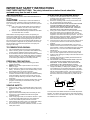
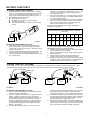
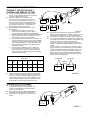
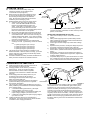
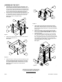
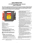
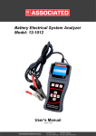
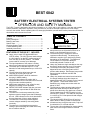
BEST 6042 ASSOCIATED BATTERY ELECTRICAL SYSTEMS TESTER OPERATOR AND SAFETY MANUAL The B.E.S.T. tester is designed to test electrical systems on 12, 12/24, and 24 volt vehicles. It can test and evaluate starters, batteries, alternators, regulators, wiring connections, and other electrical equipment in the low voltage circuits in the vehicle. Before operating this unit, thoroughly familiarize yourself with the safety instructions included in this booklet and in the service manual. TABLE OF CONTENTS VOLTS Features....................................................................... 1 Safety instructions ....................................................... 2 Battery Load Tests....................................................... 3 Starter Tests ................................................................ 5 Charging System Tests ............................................... 5 Trouble Shooting Hints ................................................ 7 Assembly Instructions.................................................. 8 AMP ADJUST DEFECTIVE DIODE LOAD ON FIELD VOLTS LOAD ADJUST 6042 ASSOCIATED FEATURES OF THE B.E.S.T. INCLUDE: AMPS SAFETY INSTRUCTION Large, easy to read, LED digital AMPS and VOLTS meters. The VOLTS meter reads voltages to ±99.9 volts DC on the EXT position and up to 35.0 volts DC on the INT position. The AMPS meter reads DC currents up to 999 amps. The input impedance of the meters is 10 Meg ohms for accurate testing of solid state circuits. The carbon pile is rated 500 amps on 12 volt batteries for load testing batteries up to 1000 CCA capacity. Curved carbon discs allow better low end resolution of current and longer life. AMPS ZERO ADJUST allows for maximum accuracy in AMPS reading. LOAD ON light indicates the carbon pile is actuated and serves as a reminder to turn the load off (full counter-clockwise position). AMPS meter reads both + and - amps for easy diagnosis of leakage current problems. DEFECTIVE DIODE indicator light lets you know when alternator output diodes or GM diode trios have failed. The electronic circuits are protected by a fuse against excessive voltage inputs that will damage the unit. LED indicators on the circuit board allow for easy diagnosis of fuse or other problems. The electronic circuits are protected against reverse voltages caused by connecting leads incorrectly. The electronic circuit board has a protective coating to prevent damage and meter inaccuracy due to moisture and dirt. 1 The FIELD selector switch is spring loaded and always returns to an off position so there is no power on the field lead when not in use. The field wire (blue) is supplied to allow for regulator trouble shooting. The lead may be switched to negative (A) or positive (B) polarity depending on the application. The lead has a circuit breaker in it to prevent damage if accidentally shorted out when in use. Heavy duty leads are single extended so the may be used for testing at points up to 15 feet apart. The clamps on the heavy duty lead are vinyl dipped and have a flexi-spring stain relief to prevent cable damage. Solid copper jaws provide better electrical conduction and are field replaceable. Heavy duty leads have internal tracer lead wires for voltage readings where the clamps are attached when the VOLTS switch is in the internal (INT) position. These leads should not be attached to any voltage source that could rise above 35 VDC. The light gauge voltage sensing leads (red and black) have small test clips to allow testing at points where the heavy duty leads can not reach. Use the leads when the VOLTS switch is in the external (EXT) position. The leads can test points in a vehicle up to 15 feet apart and read voltages up to 99.9 VDC. The inductive AMPS PICKUP has 10 foot long lead to allow for testing in hard to reach areas. All leads are long enough to test trucks, "high-rise" four wheel drive, or off road vehicles. The cart has a long wheelbase for greater stability when moved over rough surfaces or cracked floors. IMPORTANT SAFETY INSTRUCTIONS SAVE THESE INSTRUCTIONS. The safety information contained herein should be reviewed every time the unit is used. BATTERY SAFETY: TESTER PRECAUTIONS AND NOTES: ALWAYS WEAR EYE PROTECTION WHEN WORKING NEAR A BATTERY. 1) Always be sure LOAD ADJUST knob is in full counter clockwise position when disconnecting or connecting heavy duty leads to prevent arcing. 2) Never block ventilating holes on the top or the bottom of the unit. This will shorten the carbon pile life. 3) STEAM AND ODORS MAY BE RELEASED FROM CARBON PILE LOAD ASSEMBLY ANYTIME IT IS USED. THE CARBON DISCS ABSORB MOISTURE AND ODORS AS WOULD AN ACTIVATED CARBON FILTER, THESE ARE RELEASED WHEN THE CARBONS ARE HEATED. 4) A duty cycle is hard to define for a carbon pile load assembly. Size of load, length of test, time between tests, ambient temperature, and other factors affect the duty cycle. For the longest life, never let the carbon discs get red hot. This can be easily seen when running the load test. If the discs get red hot, the binder material holding the carbon granules together will start to deteriorate and lead to shortened disc life. 5) For the ammeter to read +amps, attach current probe so arrow on probe points in direction of current flow (from positive to negative). 6) Residual magnetism in the AMPS PICKUP may cause it to indicate a low current even if there is no current flow. This is a normal situation. Therefore, the AMPS meter has to be zeroed before each use. This can be done with the AMPS ZERO ADJUST knob. 7) In the booklet, the word "positive" refers to the red clamp or lead. The word "negative" refers to the black clamp or lead. 8) "Positive" when referring to a battery terminal will mean the one marked Pos, P, (+). 9) "Negative" when referring to a battery terminal will mean the one marked Neg, N, and (-). 10) PLEASE NOTE THAT THE DEFECTIVE DIODE LIGHT MAY FLASH ON AND OFF DURING SOME OF THE TESTS DESCRIBED. THIS IS NORMAL AND SHOULD NOT BE CONSTRUED TO BE A PROBLEM WITH THE UNIT. 11) During a load test, the light gauge leads may be used to read voltage across Battery 1, cable jumper, and Battery 2. These can be added up to give the total system voltage. This total may not be the same as read by the voltmeter on INT position with the clamps installed as shown. This may be caused by corrosion on terminals, rounding off by the voltmeter circuit, or other factors and does not mean there is a problem with the unit. CAUTION: The electrolyte in automotive batteries is sulfuric acid, which is capable of causing severe damage to skin, eyes, and clothing. When contact with battery acid occurs, proceed as follows: 1) Eyes: Force open and flood with cool running water at least for 10 minutes, then see a doctor. Never use eye drops or other medication before seeing a doctor. 2) Remove contaminated clothing and flood skin for at least 10 minutes with clear, cool water. While batteries are being charged or tested, an explosive gas mixture forms inside each cell. Some of this gas escape through the vent holes in the filler caps and may remain around the battery in an explosive condition. Sparks or flames igniting this gas mixture will burn back through the vent hole and explode inside the battery cell. Such an explosion is dangerous not only because of its own force, but also because of the acid electrolyte which could spray onto anything in the vicinity. TO PREVENT EXPLOSIONS: 1) 2) 3) Use well ventilated areas for charging and testing batteries. Allow no smoking, sparks or open flames near batteries being charged, tested or batteries recently charged or tested. Do not break live electrical circuits at the terminals of batteries because a spark may occur at that point causing an explosion. Always turn battery chargers or tester OFF before connecting or disconnecting the clamps from the battery terminals. PERSONAL PRECAUTIONS: 1) 2) 3) 4) 5) Wear complete protection and avoid touching eyes while working near battery. NEVER smoke or allow a spark or flame in the vicinity of battery or engine. Be extra cautious to reduce risk of dropping a metal tool onto a battery. The tool may spark or short-circuit the battery or other electrical parts which may cause an explosion. Remove personal metal items such as rings, bracelets, necklaces, and watches when working with a lead-acid battery. A lead-acid battery can produce a short-circuit current high enough to instantly weld a ring or the like to metal, and cause severe burn. Spilled acid: Neutralize with a solution of baking soda (1 pound per gallon of cold water) or household ammonia (1 pint per gallon of cold water) + VEHICLE SAFETY: 1) 2) 3) 4) 5) 6) Keep your body, clothing, and test leads away from all moving parts of the vehicle. Remember, electric fans may start at any time. Avoid hot engine parts. Engine exhaust contains deadly carbon monoxide gas. Run engine only in a well ventilated area with exhaust gases ventilated outdoors. When running engine tests, be sure that the vehicle is in "park" or "neutral" and the parking brake is on when starting the vehicle. Block wheels to prevent vehicle movement. When disabling the ignition system to run starter tests, always refer to vehicle service manual for proper procedure. Do not connect any test lead to carburetor, fuel lines, or sheet metal parts of frame. - + - 6V 6V BATTERY 1 BATTERY 2 FIGURE 1 The components in the AMPS PICKUP are somewhat temperature sensitive. As it warms near a hot engine or cools when exposed to outdoor air, the zero on the AMPS meter may drift. Once the pickup has stabilized, the zero will not drift. 2 BATTERY LOAD TESTS 4) Read the open circuit voltage (OCV) of the battery. If the voltage is 14.4 volts of higher, the load test may be run. If 12.3 volts or lower, (75% state of charge) the battery should be recharged and retested. 5) Apply a load to the battery of a ½ the CCA rating for 3 seconds to remove any surface charge. If the voltage has fallen below 12.4 volts, recharge and retest. 6) If the battery is adequately charged, apply a load to the battery of the ½ CCA rating of the battery for 15 seconds. Adjust the load as necessary during the test. Note the voltage of the battery under load and then turn the load off. The minimum acceptable voltage for a battery at the different temperatures is as follows: TESTING 12 VOLT BATTERIES: 1) 2) The standard battery load test is to apply a load on the battery equal to ½ the cold cranking amp (CCA) capacity of the battery for 15 seconds. Both the voltage and temperature of the battery under load determine whether a battery is good or not. Before testing the battery be sure that: Battery terminals are clean. The battery does not have any physical damage. The battery is not frozen. The LOAD ADJUST knob is in the full counter clockwise position BATTERY TEMPERATURE COMPENSATION 15 SECOND LOAD TEST + °C 21↑ 16 10 4 -1 -7 -12 -18 °F 70↑ 60 50 40 30 20 10 0 MIN VLT 9.6 9.5 9.4 9.3 9.1 8.9 8.7 8.5 - 12 VOLT FIGURE 2 PROPER TEST PROCEDURE IS AS FOLLOWS: 1) Attach red and black heavy duty leads to the positive and negative battery posts. Twist or rock clamps back and forth several times to make a good connection. Be sure the VOLTS switch is in INT position. 2) Attach the AMPS PICKUP around either lead of the tester. Be sure the arrow points in the direction of the current flow. 3) Adjust the AMPS meter with the AMPS ZERO ADJUST knob to give a reading of 000. IF THE CCA OF THE BATTERY IS NOT KNOWN, IT CAN BE DETERMINED BY THE FOLLOWING PROCESS: 1) Determine the temperature of the battery and find the minimum accepted voltage from the chart above. 2) Apply a load to the battery until the voltage reaches the above determined number. 3) Adjust the load as needed to maintain the voltage for 15 seconds. Note current at 15 seconds and turn load off. 4) Multiply the current reading by 2 to determine the CCA rating of the battery. Check vehicle manufacturer’s recommendation for the proper battery CCA and compare to your results. TESTING 12/24 VOLT SYSTEMS: For best results in a 12/24 volt system that has batteries connected per the diagram above, each battery should be tested separately and the connection between the batteries tested at the same time. Both battery tests should be run as described in the previous section. 6042 6042 + - + - 12V 12V BATTERY 1 BATTERY 2 RED LEAD FRAME + - + - 12V 12V BATTERY 1 BATTERY 2 FIGURE 3 BLACK LEAD FRAME FIGURE 4 PROPER TEST PROCEDURE IS AS FOLLOWS: 1) Attach heavy duty leads to Battery 1 and run battery load test. Evaluate the results. (See figure 3) 2) Attach the negative heavy duty lead to the negative terminal of Battery 2. Attach the positive heavy duty to the negative terminal of Battery 1. (By attaching at that point and not at the positive terminal of Battery 2, we will check the connection between the batteries at the same time.) Attach the negative light gauge voltage lead to the positive terminal of Battery 2 and the positive light gauge lead to the negative terminal of Battery 1. (See figure 4) 3) Run the battery load test on battery 2. At the end of the 15 4) 5) 3 seconds and with the load still on the battery, switch VOLTS to EXT position and read the voltage drop across the cable connecting the 2 batteries. Turn load off and evaluate results. To evaluate the battery load test, the voltage drop read across the cable (EXT position) has to be added to read the voltage on the INT position to give the proper battery voltage. Evaluate the battery based on this voltage (EXT + INT). Evaluate the cable jumper between the batteries, based on the voltage read on the EXT position. A typical acceptable voltage drop is 0.2 volts. Check the service procedure for the vehicle if there is any question about the acceptable voltage drop. USE THIS SECTION FOR BATTERY TESTING IF YOU’RE 12/24 VOLT SYSTEM LOOK SIMILAR TO THIS: One six volt battery by itself cannot be tested with this unit. It will not provide enough power under load to allow the digital circuitry to work. Please note: When two six volt batteries are connected in series, the voltage of the array is 12. + The CCA rating of the series does not double. It is 6V the same CCA as either of the individual batteries. BATTERY 1 (If you have two, 500 CCA, 6 volt batteries in series, it is equivalent to a 500 CCA, 12 volt battery and should be tested with a 250 amp load.) + Both the heavy duty and light gauge leads will be 6V used in this test. BATTERY 3 1) Attach the positive heavy duty lead to the positive terminal of Battery 1 and the negative heavy duty lead to the negative terminal of Battery 2. 2) The light gauge leads will be used to read voltages across Battery 1, the cable connection, and Battery 2, so the VOLTS switch should be in the EXT position. 3) Apply the proper load to the batteries for 15 seconds. At that time and with the load on, read the voltage of Battery 1 (red lead to positive, black lead to negative), the cable jumper (red lead to Battery 1, negative and black lead to Battery 2 positive), and Battery 2 (red lead to positive, black lead to negative). 4) Turn load off and evaluate the results. Voltage drop across the cable jumper should be 0.2 volts or less. If there is any question, check the service manual of the vehicle. Minimum acceptable voltage for a 6 volt battery at different temperatures is: + 21↑ 10 2 -4 -9 -15 °F 70↑ 50 35 25 15 5 MIN. VOLT 4.8 4.7 4.6 4.5 4.4 4.3 RED LEAD BATTERY 2 + - BATTERY 4 FIGURE 5 The voltage read under load from the positive terminal of Battery 1 to the negative terminal of Battery 2 is the sum of the voltage drops across Batteries 1, 2, and the cable jumper. Total voltage = B1 voltage + B2 voltage + jumper voltage drop. If you had two good batteries and a bad jumper connection, the total voltage may be less than acceptable. If the batteries were replaced, the new ones may test bad due to the bad connection. Replacing or cleaning a bad jumper cable is cheaper and easier than replacing batteries if that is all that is needed. In another situation, you may have one good battery, a good jumper connection, and one bad battery. If the good battery voltage is high enough to offset the bad battery voltage, you will have no indication of the potential problem. If the good battery voltage is not high enough to offset the bad battery voltage, the group may test bad and both batteries replaced when only one of the needs to be. B1 VOLTAGE B2 VOLTAGE JUMPER + BLACK LEAD 6V BATTERY TEMPERATURE COMPENSATION 15 SECOND LOAD TEST °C 6V Please note that the test described above is not the easiest way to run a test on two batteries in series, but it is the most accurate. If you were to test the batteries and take only one voltage reading from the positive terminal of Battery 1 to the negative terminal of Battery 2, there are problems that could remain hidden or cause excessive replacement costs. - + - 6V 6V BATTERY 1 BATTERY 2 FIGURE 6 TESTING 24 VOLT SYSTEMS: 24 volt batteries may be tested by the same procedure as described for 12 volt batteries. The minimum acceptable voltages will be twice what is listed for 12 volt batteries. LOAD TESTS ON 24 VOLT BATTERIES SHOULD BE LIMITED TO 300 AMPS FOR 15 SECONDS. Higher currents or longer times may shorten carbon pile life. + - 24 VOLT FIGURE 7 4 STARTER TESTS Current draw of the starter, battery voltage, and voltage drop of leads can be measured when connected as shown (See figure 8). Before running any starter tests, disable the engine FRAME by removing the coil wire from the distributor or by STARTER disconnecting the battery leads to the distributor SOLENOID (HEI). Be sure that any leads that are removed are insulated to prevent shorting to ground. Review the Safety section in the front of this manual. 1) Attach the heavy duty leads to the battery as shown. Attach the AMPS PROBE around the lead from the positive battery terminal to the starter. If that cable is not accessible, it may be placed around the ground cable that runs from the frame or engine block to the negative battery terminal. Make sure VOLTS switch is in INT position. 2) Be sure that all the lights and accessories are turned off. 3) Crank the engine while watching both the VOLTS meter and the AMPS meter. After 2-3 seconds of cranking, the readings should be fairly stable. If not, continue cranking until they are stable. Under no condition should you crank more than 10 seconds at a time. 4) Minimum acceptable voltage for most vehicles while cranking is 9.6 volts. Typical starting currents for vehicles are: 4 cylinder gas engine--up to 175 amps 6 cylinder gas engine--up to 225 amps 8 cylinder gas engine--up to 250 amps 8 cylinder gas engine--up to 650 amps The vehicle service manual should be consulted for more detailed information. While the vehicle is cranking, you should listen for high pitch or low growling sounds that may indicate bearing or other problems. Connections between the battery and starter and between the battery and frame should also be checked at this time. STARTER MOTOR RED LEAD + - BLACK LEAD FRAME FIGURE 8 Excessive voltage drop in either cable caused by loose or corroded connections, undersized, or broken wires may be the problem, not the starter. PROPER TEST PROCEDURE IS AS FOLLOWS: 1) Attach tester to battery as shown. Switch VOLTS to EXT position. 2) Attach positive light gauge lead to positive battery terminal. Attach negative light gauge lead to starter solenoid where the lead from the battery terminates. 3) Crank engine and read voltage drop of cable when readings stabilize. 4) Repeat the same procedure, checking the voltage drop across the solenoid, (negative lead to starter side of solenoid). 5) Repeat again, checking the voltage drop between the solenoid and the starter. (Positive lead at solenoid, negative lead at starter.) 6) Repeat again, checking the ground cable from the battery to the engine block. (Positive lead to engine block, negative lead to battery negative terminal.) 7) Acceptable voltage drop on any wire lead should be 0.2 volts or less. Voltage drop across the starter solenoid should 0.3 volts or less. Check vehicle service manual for further details. CHARGING SYSTEM TESTS ALTERNATOR Please review all the safety instructions in the front of this manual before running these tests. Charging problems can be caused by a number of FRAME different things. These can include loose belts, defective diodes or stators, defective regulators, corroded or loose connections or defective diode trios (GM cars). Undercharging will shorten battery life and may not provide the proper charge to start the vehicle. Overcharging will cause excess water usage in the battery and shorten battery life. FRAME RED BLACK + Proper charging voltage and current from the charging TO LEAD LEAD system to the battery is important for the longest life ACCESSORIES FIGURE 9 and maximum performance. It is also important that the charging system be capable of putting The proper end of charge voltage will depend on the type of out it's rated current. If the electrical load, (lights, blower, power battery installed by the manufacturer and ambient temperature accessories, etc.) in the vehicle is more than the output of the of the charging system. alternator, the battery will discharge to provide the needed current. ● A conventional battery (lead-antimony ) will require The battery may become discharged and will not recharge until charging voltages up to about 14.5 volts. some of the load is turned off. This type of discharge/charge cycle ● A recombination battery or low maintenance battery will will greatly shorten the life of the battery. Therefore, output current require charging voltages up to about 15.0 volts. as well as output voltage of the charging system should be checked. ● A maintenance free battery will require charging voltages NOTE: A check of the charging system should include a check of up to about 15.5 volts. the battery cables to ground and to the alternator to determine bad Voltage specifications will vary from manufacturer to connections. manufacturer. The service manual for the vehicle should be consulted for exact charging specifications. 5 OUTPUT VOLTAGE TEST: 1) 2) 3) 4) It should be within 10% of the manufacturer's specification to be acceptable. If a number of accessories have been added to the vehicle, the alternator output should be high enough to supply the total accessory load. Connect tester to battery as shown. Connect AMPS PICKUP around positive output cable of alternator. If wires split off to feed power to accessories, the pickup must be placed over the wires between the point the split and the alternator. Do not place the pickup closer than 6 inches to the alternator or the current readings may be affected by the magnetic field of the alternator. VOLTS switch should be in INT position. Make sure all accessories are off in the vehicle. Start vehicle and allow the engine to run at fast idle until the current output from the alternator is between 0-10 amps. Read the output voltage. Proper output voltages should be as listed previously. REMEMBER: Charging systems in a vehicle will compensate for ambient temperatures by increasing the charging voltage at low temperatures. Check the vehicle service manual for proper charging voltages at low temperatures. OUTPUT DIODE/STATOR TEST: 1) 2) 3) 4) OUTPUT CURRENT TEST: Connect the tester as above and run the vehicle at fast idle. Apply a load to the battery to obtain the highest reading on the ammeter. Do not allow the battery voltage to drop below 12.0 volts. This ammeter reading is the maximum output of the alternator. Attach the tester as shown in the above diagram. Attach the light gauge positive lead to the positive output terminal of the alternator. Attach the light gauge negative lead to the frame (ground) of the alternator. VOLTS switch should be on EXT position. Start vehicle and run at a fast idle. Apply a load to the battery as described in the OUTPUT CURRENT TEST. Defective output diodes or a stator problem will turn the DEFECTIVE DIODE light on in 1-2 seconds and it will glow steadily. If the light blinks on and then stays off, there are no defective parts. If the positive output terminal of the alternator is inaccessible, the positive lead may be connected to the positive terminal of the battery and the test run as described. The accuracy of the test may be affected by loose or corroded terminals or an undersized cable. Attach leads to rear of alternator if possible. GM DIODE TRIO TEST: SCREWDRIVER The diode is located inside the GM alternator and must be checked The diode trio is located inside a GM alternator and must be checked whenever alternator problems are suspected. These diodes are separate from the output rectifier of the alternator. They are used as part of a feedback loop to the internal regulator. 1) 2) 3) 4) 5) 6) Attach the heavy gauge leads to the battery. VOLTS switch should be in EXT position. Attach the black light gauge lead to the negative battery post or frame of alternator. Attach the red light gauge to the number 1 terminal of the plug in the alternator. DO NOT DISCONNECT THE PLUG FROM THE ALTERNATOR. DAMAGE MAY RESULT IF THE PLUG IS DISCONNECTED. Start the engine and let run at normal idle. Do not apply any load to the battery. If the DEFECTIVE DIODE light comes on and stays on, it indicates a defective diode trio. The alternator should be repaired or replaced. RED LEAD TERMINAL 1 ALTERNATOR PLUG FIGURE 10 ALTERNATOR OUTPUT TEST: (Bypassing the regulator) If the alternator did not pass the first output test that was run, this test should be performed to determine whether the alternator or regulator is at fault. Determine from the vehicle service manual whether the regulator is type "A" or "B". 1) 2) 3) 4) 5) 6) REGULATOR F FIELD WIRE FROM ALTERNATOR TO REGULATOR Connect the unit to the vehicle as shown (See figure 11). Disconnect the lead wire from the field terminal of the alternator or regulator. Attach the blue test lead to the field terminal of the alternator or, if disconnected at the regulator, the wire that leads from the regulator to the field terminal. (IF THE LEAD FROM THE REGULATOR IS NOT DISCONNECTED AT ONE END OR THE OTHER, DAMAGE MAY OCCUR TO THE UNIT WHEN TESTING.) Start the engine and adjust engine speed to about 2000 RPM. Apply a load to the battery to reduce the system voltage by about 2 volts. Hold the spring loaded FIELD selector switch in the proper position. In the "A" position, the field lead is connected to the negative terminal. In the "B" position, the field lead is connected to the positive terminal. This is called "full fielding" the alternator. Pushing the switch into the wrong position will not damage the alternator. F FRAME ALTERNATOR + - FRAME FIGURE 11 7) 8) 9) 6 Adjust the lead applied to the battery to give the maximum current reading without dropping the voltage below 12.0 volts. Release the FIELD switch and turn off the load on the battery. If the alternator output is not at least tested 90% of its rated output, repair or replace the alternator. If the current reading on the ammeter is within 10% of the manufacturer's rating, the alternator is good and the regulator should be replaced if the wiring to it is found to be good by these checks. A GM ALTERNATOR HAS A DIFFERENT PROCEDURE FOR FULL FIELDING: 1) 2) Locate a "D" shaped hole in the rear of the alternator. Insert a small screwdriver or any other metal rod in the hole until you contact a metal tab (less than 3/4 inch). Ground the screwdriver or rod to the case and apply a load per above instructions. If the regulator is determined to be bad, check that it is making a good ground connection to the vehicle chassis. Also, check that the wire from the regulator to the alternator field terminal is making good connections and does not have any breaks in it. MEASURING SMALL CURRENTS: DEVICE UNDER TEST The BEST tester will measure currents down to one amp in value. If smaller currents need to be measured, follow the steps below. TO CHECK CURRENT DRAW OF A SPECIFIC ELECTRICAL DEVICE: 1) 2) 3) 4) 5) 6) DISCONNECT POWER TO DEVICE UNDER TEST Attach unit to battery as shown. Disconnect the power lead to the device under test. Coil the field lead of the unit 10 times around your hand and connect the clip to the power input terminal of the device under test. Clip the AMPS PICKUP around the 10 turns of wire. Press the FIELD switch to the "B" position and read the ammeter on the unit. Divide the ammeter reading by 10 to give the actual current draw of the device under test. BLUE LEAD (FIELD) + - FRAME FIGURE 12 TO CHECK CURRENT DRAW OF ENTIRE ELECTRICAL SYSTEM: 1) 2) 3) 4) 5) 6) Disconnect the negative load from the battery. Attach unit as shown (See figure 13). Clip blue lead to the negative wire just removed from the battery. Wrap the blue lead around your hand 10 times and clip AMPS PICKUP around the coil. Push FIELD switch to the "A" position. Read the ammeter. Release switch. Divide ammeter reading by 10 to give the total current draw of the vehicle from the battery. + - FRAME BLUE LEAD (FIELD) FRAME FIGURE 13 6042 B.E.S.T. TESTER TROUBLE SHOOTING HINTS: If the meter displays fail to light when the unit is connected to a charged battery, remove the unit's cover and look at the back of the circuit board. There are two LED's in the top middle of the board. If both of these are lit, there is a problem on the circuit board that must be diagnosed by a factory technician. If one LED is lit, the fuse on the rear of the board is blown and should be replaced. Replace with an AGC 1 fuse. The fuse blew to protect the board against an over voltage situation that would have damaged the solid state components on the board. If neither LED is lit, there is no incoming power to the circuit board. Check for good connection at the battery. Also check (with an ohmmeter) the tracer lead in the heavy duty leads to be sure there is a circuit from the clamp jaws to the power strip on the circuit board. PARTS LIST ITEM 1. 2. 3. 4. 5. 6. 7. 8. 9. 10. 11. 12. 13. 14. 15. 16. 17. 18. ASSEMBLY INSTRUCTIONS Parts included with this unit are listed in the part list. Item numbers appear on the exploded view, part list and throughout the text for easy reference. 7 QTY DESCRIPTION 1 ........................................................................ Lower Tray 1 ........................................................................ Upper Tray 2 ......................................................................... Back Legs 20 ..................................................................¼-20x2” Bolts 20 .....................................................................¼” Washers 20 ................................................................ ¼-20 Hex Nuts 2 .........................................................................Front Legs 1 ...........................................................................Top Plate 1 ...............................................................................Handle 4 ................................................... #10x1” Machine Screws 4 ................................................................. 10-24 Hex Nuts 1 ........................................................ B.E.S.T. Control Unit 4 ....................................................................... Plastic Feet 4 ............................................... #10x1 ¼” Machine Screws 2 ...........................................................................Axle Nuts 1 ................................................................................... Axle 2 .............................................................................. Wheels 2 ...................................................................................Feet ASSEMBLING THE CART: 1. 2. Place lower tray (1) and upper tray (2) on flat surface. Align the lower holes in back leg (3) with holes in lower tray (1), fasten the back leg to lower tray with 2 each bolts (4), washers (5) and nuts (6). Align the middle holes in back leg with holes in upper tray and fasten with 2 each bolts (4), washers (5) and nuts (6). Note: At this time only finger tighten the bolts and nuts, so the frame can be easily adjusted to square later. Place front leg (7) onto lower and upper trays aligning the holes in all three parts. Attach the front leg to both trays with bolts (4), washers (5) and nuts (6). Flip the cart over 180° and repeat steps 1 and 2 for the right side legs. See Figure 1. 12 14 13 4 3-1 5 6 Figure 3 5. 7-1 6. 7. 1 2 8. Figure 1 3. Attach the top plate (8) and handle (9) with 4 each of #10x1” screws (10) and #10 nuts (11). See Figure 2. 8 Tap one axle nut (15) onto one end of the axle (16) with a rubber mallet. Slide one wheel (17) onto the axle. Push the axle through the holes located on the bottom of the back legs. Slide the second wheel onto the axle. Tap the second axle nut onto the axle. Press the feet inserts (18) into the bottom of the front legs. Make sure the frame is square before tightening all bolts and nut to a snug fit. DO NOT OVER-TIGHTEN, over-tightening can deform the legs. Place the top plate/control unit assembly on the assembled cart. Fasten the top plate to the back legs with 2 each bolts (4), washers (5) and nuts (6). Attach the top plate to the front legs. The top plate has two pairs of holes so the viewing angle can be adjusted. Bolting through the top pair of holes will mount the top plate in a flat position. The lower pair of holes will elevate the plate at a 15° viewing angle. See Figure 4 11 4 5 6 10 9 17 Figure 2 4. Attach the B.E.S.T. control unit (12) to the top plate (8). Place the feet (13) between top plate and control unit. Flat side of foot is placed against top plate. Insert the #10x1 ¼” screws (14) through top plate and feet and thread into the threaded fasteners in the four corners of the control unit base. See Figure 3. 18 15 16 Figure 4 ASSOCIATED EQUIPMENT CORPORATION 5043 Farlin Avenue Saint Louis, Missouri 63115 Tel. (314) 385-5178 Fax. (314) 385-3254 www.associatedequip.com Z4041 027-0278 Rev. 20100204 8