1
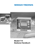
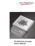
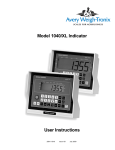
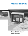
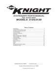
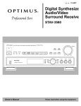
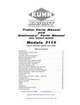
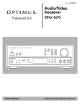
Model 715
User’s Manual
CAUTION
Risk of electrical shock. Do not remove cover. No user serviceable parts inside. Refer servicing to qualified service personnel.
Weigh-Tronix reserves the right to change
specifications at any time.
08/13/03 715_U.P65 PN 29590-0013M e1 Printed in USA
2
Model 715 User’s Manual
Table of Contents
Table of Contents ................................................................................................. 3
Model 715 Indicator .............................................................................................. 5
Key Functions ............................................................................................ 5
Operational Overview ........................................................................................... 6
Operational Modes .................................................................................... 6
Pressing the Keys ...................................................................................... 6
Using a Printer ........................................................................................... 8
Cable Connections and Power Requirements ...................................................... 8
Weighing ............................................................................................................ 10
Loading Ingredients ............................................................................................ 10
Unloading Batched Ration .................................................................................. 12
Loading or Unloading a Mixer Wagon ................................................................ 13
Increasing Net Weight ............................................................................... 3
Maintaining Displayed Weight ............................................................................ 14
Correcting for Display Shift ................................................................................. 15
Platform Scale Operations: Vehicle Weighing .................................................... 16
Appl. #1 - Loading a Vehicle .................................................................... 17
Appl. #2 - Weighing a Vehicle for Net Weight and Gross Weight ........... 18
Appl. #3 - Weighing a Vehicle for Net Weight and Tare Weight .............. 19
Appl. #4 - Weighing a Loaded Vehicle Using Known Tare Weight .......... 20
Troubleshooting .................................................................................................. 21
Power-on Failure ..................................................................................... 21
Stalled DIsplay Following Power-On ........................................................ 22
Indicator Lock-up ..................................................................................... 23
Inaccurate Weight Readings ................................................................... 23
Service Repairs ....................................................................................... 24
Display Messages .................................................................................... 24
Mounting the 715 Farm Indicator ........................................................................ 25
RD712/XL Remote Display ................................................................................. 26
Specifications, Features, Options ....................................................................... 27
Pages are numbered consecutively beginning with the cover page.
Model 715 User’s Manual
3
This page left intentionally blank.
4
Model 715 User’s Manual
Model 715 Indicator
Figure 1
Front Panel of Model 715 Indicator
Key Functions
ON
1. Press to power-on the indicator to mode last displayed
before removal of power;
2. Press in conjunction with ZERO/RESET to reinitialize
Indicator.
OFF
Press to remove power.
HOLD
Press to access Manual Hold Mode, which protects the scale
against display shift so you can move the scale.
GROSS
1. Press to access Gross Mode and view live gross weight;
2. Press to correct display shift in Gross Mode after keying in
correct previous gross weight.
PRINT
Press to transmit displayed value for printing.
LOAD/UNLOAD
ZERO/RESET
Numeric Keys
1. Press to access Load/Unload Mode;
2. Press for mixer wagon and platform scale weighing,
to access Load/Unload Mode (See operating instructions).
1. Press to zero-balance the scale;
2. Press to reset net load/unload value back to lastentered load/unload value—for loading or unloading a
series of equal quantities;
3. Press to tare out displayed weight and return net
display to zero;
4. Press to delete a keyed in value, if pressed immediately after keying-in.
Ten keys, 0 - 9, used to key in values.
Model 715 User’s Manual
5
Operational Overview
The Model 715 Indicator is ideal for interfacing with a portable/ stationary
feed mixer for use in weight-based batching operations.
Additionally, the Model 715 can function in mixer wagon applications, for
loading and unloading, and in platform scale applications, to display and
print gross, tare, and net weight values.
Operational Modes
The Model 715 Indicator has two operational modes: Gross Mode and Load/
Unload Mode. The GROSS key selects Gross Mode, and the LOAD/
UNLOAD key selects Load/Unload Mode.
Value displayed in Gross Mode represents total live scale weight.
In a portable feed mixer application, the indicator performs loading and
unloading procedures the same way, by loading or unloading net Target
Quantities of a gross total.
• For ingredient-loading, value displayed in Load/Unload Mode
represents the Target Load Quantity of ingredient remaining to be
loaded.
• For ration-unloading, value displayed in Load/Unload Mode represents the Target Unload Quantity of ration remaining to be unloaded.
The two operational modes of the Model 715 can also be used for mixer
wagon loading and for platform scale weighing. One platform scale
application allows you to load a container positioned on a platform while the
indicator displays decreasing net weight of material remaining to be loaded
into the container. Additional platform scale applications use Load/Unload
Mode as a Net Weighing Mode, allowing you to weigh empty containers or
full containers with gross-tare-net weighing sequences typical for platform
scales.
Pressing the Keys
When you press a key correctly, the display blinks; the single blink always
means that the key has made proper internal contact for activating your
intended function.
Because extreme cold tends to inhibit the reaction of liquid crystal, you can
expect that in very cold weather the display may take longer than usual to
respond to keyed requests. To obtain the display blink as a guarantee that
you have accessed Gross Mode or Load/Unload Mode in very cold weather,
you may need to press and hold the key longer than usual.
Indicator ZERO/RESET Key
The Indicator’s ZERO/RESET key serves several functions. It is used to
• Reset the display, following a single load or unload cycle, back to the
Target Quantity of the load just concluded—a convenience when
handling a series of equal quantities.
• Tare Out the displayed value, resetting the display to zero.
• Delete a keying error from the display, if pressed immediately after the
error’s occurrence.
• Zero the scale.
6
Model 715 User’s Manual
Remote ZERO/RESET Key
Both the RD712/XL Remote Display and the XM710 Hand-Held Transmitter
have ZERO/RESET keys that function identically to ZERO/RESET on the
indicator. Remote access to functions of ZERO/RESET is a convenience for
both portable feed mixer and mixer wagon applications.
• In a Portable Feed Mixer Application, the remote ZERO/RESET key
returns displayed net value to your keyed-in Target Quantity, allowing
you to continue loading or unloading identical quantities—without
returning to the Indicator.
• In a Mixer Wagon Application, the remote ZERO/RESET key tares
out displayed net value, resetting the display to zero, and you avoid
returning to the Indicator between each load. Holding in ZERO/RESET
for more than two seconds between loads also allows you to view
gross weight.
• In All Applications, the remote ZERO/RESET key shuts off your
alarm and zeroes the scale system.
HOLD Key
Auto Hold Mode and Manual Hold Mode protect scale weight against the
effects of display shift, which can occur when you move your portable scale
system over uneven terrain. Auto Hold Mode is accessed automatically in
the course of normal loading and unloading. The HOLD key accesses
Manual Hold Mode.
Both the Auto Hold Mode and the Manual Hold Mode are represented on
the display by (1) the word Hold alternating with (2) actual net quantity just
loaded or unloaded.
After the loading of a micro ingredient—an ingredient that is smaller than
the preprogrammed warning alarm value—the system does not automatically progress into the Auto Hold Mode. However, the HOLD key will get you
into the Manual Hold Mode following micro-loading.
If Auto Hold Mode has ben disabled on your indicator by internal programming, the HOLD key still accesses Manual Hold Mode.
Model 715 User’s Manual
7
Using a Printer
If you have a printer, press the PRINT key to print the currently displayed
value. Printed data includes the displayed value and the correct unit of
measure, Ib or kg. In a load or unload procedure, printed data also includes
a number reflecting Auto Ingredient Numbering function; the number actually
counts load or unload cycles.
Figure 2:
WP-233 Printer Output for an Ingredient-Loading
Procedure;
five single ingredient quantities and total batch weight
represent six separate print transmissions.
Cable Connections and Power Requirements
Make sure all cables are connected as shown in Figure 3.
Voltage to the Model 715 must be 10-18 volts DC, negative ground only. If
voltage ever drops to below ten volts, the Model 715 will automatically shut
itself off, protecting the battery from being completely drained. Consult the
Model 715 Service Manual for instructions on disabling the automatic shutoff.
8
Model 715 User’s Manual
Pin A = +12 VDC
Pin B = Ground
Pin A = +12 VDC
Pin B = Ground
Pin A = +12 VDC
Pin B = Ground
Figure 3
Cable Connections
Model 715 User’s Manual
9
Weighing
GROSS MODE is required for
zeroing. Your indicator must be
zeroed before weighing begins.
1. Press ON . . .
Display says HELLO, then value is
displayed in mode last used before
removal of power.
2. Press GROSS . . .
Live scale weight is displayed in
Gross Mode.
3. Press ZERO/RESET . . .
Zero value is displayed. Weighing
system is zeroed.
4. Place weight on the scale . . .
Live gross weight of material is
displayed.
Loading Ingredients
1. Zero indicator before loading first
ingredient.
If you miskey Target Load
Quantity, simply press ZERO/
RESET to delete, then rekey.
2. Key in Target Load Quantity . . .
Quantity you intend to load is
displayed.
3. Press LOAD/UNLOAD . .
Target Load Quantity blinks and
remains displayed.
4. Load ingredient into portable
feed mixer, viewing display as
you do so . . .
Displayed value, showing net
amount of your keyed-in Target
Quantity remaining to be loaded,
decreases from Target Load Quantity toward zero.
Alarm light flashes on and off when
display has decreased to
preprogrammed warning value,
warning you to watch the display and
giving you time to coordinate stoppage of material flow with display of
zero net value.
5. When appropriate, stop loading . . . When net weight of ingredient
remaining to be loaded has decreased to zero value or less, alarm
light quits flashing and stays on.
Micro-ingredients weighing less
than the preprogrammed
warning alarm value will not
activate alarm function.
10
6. Press any key on the front
panel . . .
Model 715 User’s Manual
Steady alarm light shuts off, and
indicator advances into Auto-Hold
Mode, a holding mode that protects
gross weight and displayed weight
so you can move the scale.
If you exit Auto Hold Mode to
view gross weight or overshot/
undershot value prior to
moving your scale, you may reenable the holding capability by
pressing HOLD, for Manual
Hold Mode.
MICRO-INGREDIENT loadings
will not advance into Auto Hold
Mode. From micro-loading you
may access Manual Hold Mode
with HOLD key.
IF YOU HAVE A PRINTER,
you may print actual net weight
of just-loaded ingredient by
pressing PRINT from either
Hold Mode.
In Auto-Hold Mode, the display
alternates between (1) Hold, and (2)
actual weight of ingredient just
loaded.
7. Move feed mixer to its next
ingredient-loading station while
system is in either Auto or
Manual Hold Mode, Hold
alternating with net weight
display.
8. Do either A or B:
A. Key in a new Target Load Quantity, then press LOAD/UNLOAD . .
OR
B. Press ZERO/RESET, (with no
depression of LOAD/UNLOAD), to
restore last-loaded Target Quantity
as the next Target Load Quantity—
a convenient technique for loading a
series of equal quantities . . .
Indicator is ready for another ingredient-loading cycle.
9. Repeat Steps 4 through 8 for
each ingredient you want to load,
stopping with final ingredient
after Step 6.
Model 715 User’s Manual
11
Unloading Batched Ration
1. Move feed mixer to rationunloading site when loading is
completed, while Hold alternates
with weight display.
If you miskey the Target
Unload Quantity, press ZERO/
RESET to delete, then rekey.
2. Key in Target Unload Quantity . . . Quantity you intend to unload is
displayed.
3. Press LOAD/UNLOAD . . .
4. Unload batched ration from
portable feed mixer, viewing
display as you do so .
Target Unload Quantity blinks and
remains displayed.
Displayed value, showing net
amount of your keyed-in Target
Quantity remaining to be unloaded,
decreases from Target Unload
Quantity toward zero.
Alarm light flashes on and off when
display has decreased to
preprogrammed warning value,
warning you to watch the display and
giving you time to coordinate stoppage of material flow with display of
zero net value.
5. When appropriate, stop
unloading . . .
IF YOU EXIT AUTO-HOLD
MODE to view gross weight or
overshot/undershot value prior
to moving your scale, you may
re-enable holding capability by
pressing HOLD, for Manual
Hold Mode.
IF YOU HAVE A PRINTER,
you can print actual net value
of last quantity unloaded by
pressing PRINT from either
hold mode.
12
6. Press any key on the front
panel . . .
When net weight of ration remaining
to be unloaded has decreased to
zero value or less, alarm light quits
flashing and stays on.
Steady alarm light shuts off, and
indicator advances into Auto-Hold
Mode, a holding mode that protects
gross weight and displayed weight
so you can move the scale.
In Auto-Hold Mode, the display
alternates between (1) Hold, and (2)
actual weight of ration just unloaded,
preceded by a minus sign.
7. Continue unloading by moving
feed mixer to its next rationunloading station while system is
in either Auto or Manual Hold
Mode, Hold alternating with net
weight display.
Model 715 User’s Manual
8. Do either A or B:
A. Key in new Target Unload Quantity, then press LOAD/UNLOAD . . .
OR
B. Press ZERO/RESET, (with no
depression of LOAD/UNLOAD), to
restore last-unloaded Target Quantity as next Target Unload Quantity—
a convenient technique for unloading
a series of equal quantities . . .
Indicator is ready for another rationunloading cycle.
9. Repeat Steps 4 through 8 for
each quantity of batched ration
to be unloaded, stopping with
your final unloading after Step 6.
Loading or Unloading a Mixer Wagon
The warning alarm (alarm light) is nonfunctional in this loading/unloading
procedure.
Increasing Net Weight
Use this procedure to load a series of quantities onto the weighing system
by watching the net weight of each additional load increase from zero. This
procedure also allows you to unload a series of quantities from the weighing system by watching the net weight of each unload quantity increase from
zero.
1. Zero the Indicator, but do this
only before loading the first in a
series of loadings.
GROSS WEIGHT The Indicator accumulates gross weight
value of successive load or
unload quanhties. You may
press GROSS to view the
gross weight at any time, and
LOAD/UNLOAD to return to
net display.
2. Press the numeric 0 key . . .
Display blinks and zero value
remains displayed.
3. Press LOAD/UNLOAD . . .
Display blinks again and zero value
remains, the display now reflecting
Net Weighing Mode.
4. Load or unload material and
observe the display, as. . .
5. Stop loading or unloading
material at desired net value.
6. Press ZERO/RESET . . .
To Continue Loading or
Unloading Successive
Quantities:
Net weight value increases.
7. You may now view gross weight.
Just press and hold in the
ZERO/RESET key on your 715
Indicator or your XM710
Hand-held Transmitter . . .
Model 715 User’s Manual
Displayed net value of material last
loaded or unloaded is reset to zero.
Display blinks, zero value is displayed for two more seconds, then
gross weight is displayed.
13
8. Release the ZERO/RESET
key . . .
Zero is again displayed in net
weighing mode.
9. Load or unload additional
quantities by repeating Steps 4
through 9 as many times as
required for this
loading/unloading operation.
Maintaining Displayed Weight
Hold Mode Voids Effects of Moving
The Model 715 Indicator provides a Hold Mode that can stabilize the weighing function so that moving-induced effects are not measured or registered;
weighing capability is re-engaged when you relocate the system and exit the
Hold Mode to continue weighing. By using Hold Mode, you can be certain
that the scale measures only what you want it to measure.
The Model 715 provides both automatic and manual access to the Hold
Mode.
Auto Hold Mode
In a typical moving procedure the scale is protected
from display shift by Auto-Hold
Mode.
Micro-ingredient loading
does not advance into Auto
Hold Mode.
Auto Hold allows the Model 715 to stabilize gross and net weight so you can
move the scale, following the typical operating procedure of moving the
scale after you finish one load or unload cycle, and before you enter another
Target Quantity.
Auto-Hold Mode is enabled, and you may move the scale, while the
display alternates between
(1) Hold, and
(2) actual weight of material just loaded or unloaded.
After micro-ingredient loading, access Manual Hold Mode
before moving the scale.
You may press PRINT from Auto Hold Mode to transmit to a printer the justloaded or unloaded quantity.
Manual Hold Mode
Manual Hold allows you to re-enable the Hold Mode in case you have exited
Auto Hold prior to moving the scale. This means you can check the gross
weight and/or the overshot/undershot quantity right after loading or unloading, and restore the holding capability before moving.
Press HOLD . . .
Manual Hold Mode is enabled; the scale is protected against display
shift and it is safe to move the scale while you see the display alternate
between
(1) Hold, and
(2) actual weight of material just loaded or unloaded.
You may press PRINT from Manual Hold Mode to transmit to a printer the
just-loaded or unloaded quantity.
14
Model 715 User’s Manual
Correcting for Display Shift
For circumstances when you move the scale without the protection of Hold
Mode, resulting in display shift, the Model 715 allows correction of the
display in both Gross Mode and Load/Unload Mode.
In Gross Mode:
Key in correct gross weight, and press GROSS . .
Former correct gross weight is displayed, and Load/Unload Mode is
corrected as well.
NOT TYPICAL
Although the last sequence
described is not the intended
order of operation, it can easily
happen. Normally, you would
first move the system, and then
key in a Target Quantity,
pressing LOAD/UNLOAD
immediately before loading or
unloading.
In Load/Unload Mode:
If you observe display shift following this sequence:
• key in a Target Quantity,
• press LOAD/UNLOAD,
• then you move the weighing system;
before depressing any other keys, press ZERO/RESET . . .
Display will now show Target Quantity as you keyed it in. This method of
correction allows accurate weighing of net Target Quantity but does not
correct gross weight; the gross weight reading will still be off by a value
equal to the amount of the display shift.
Model 715 User’s Manual
15
Platform Scale Applications: Vehicle Weighing
#1.
Loading a Vehicle
#2.
Weighing a Vehicle for Net Weight and Gross Weight
Tare————
➤Gross Weighing
➤Net————
#3.
Weighing a Vehicle for Net Weight and Tare Weight
➤Net————➤Tare Weighing
Gross————
#4.
Weighing a Loaded Vehicle Using Known Tare Weight
Your dealer or distributor can internally reconfigure the Model 715 Indicator
for these platform scale / vehicle weighing applications. For optimum ease
of use, Auto Hold Mode should be disabled for Application #1 and #4, and
the warning alarm value should be set to zero for Application #4.
16
Model 715 User’s Manual
Platform Scale
Application #1
Loading a Vehicle
AUTO-HOLD MODE should be
disabled for this procedure.
Use this procedure to load a vehicle and observe net weight counting back
from your keyed-in Target Load Quantity to zero.
1. Empty and zero the scale.
2. Drive empty vehicle onto scale
platform.
3. Key in your Target Load Quantity
(the net weight of material you
intend to load) . . .
4. Press LOAD/UNLOAD . . .
DECREASING NET VALUE on
the display shows you at any
given moment how much
material remains to be loaded.
5. Load material onto vehicle,
viewing display as you do so . . .
Net Target Load Quantity is displayed.
Display blinks; Target Load Quantity
remains displayed.
Displayed net value decreases from
Target Load Quantity toward zero.
Alarm light flashes when display has
reached preprogrammed alarm
value, warning you to watch display
so you can coordinate stoppage of
material flow with zero net value.
6. When appropriate, stop loading
material . .
When net display of quantity remaining to be loaded has decreased to
zero or less, alarm light quits flashing and stays on.
7. Press any key to shut off alarm.
8. Execute appropriate keying
sequence:
HOLD displays net quantity loaded.
LOAD/UNLOAD displays quantity
overshot.
GROSS displays gross weight of
vehicle plus total quantity of material
on vehicle.
Model 715 User’s Manual
17
Platform Scale
Application #2
Weighing a Vehicle for Net
Weight and Gross Weight
Tare————➤Net————➤Gross Weighing
In this procedure you first weigh an empty vehicle to get the tare weight,
then you load the vehicle and use the Indicator to obtain net and gross
weights.
1. Empty and zero the scale.
TARE WEIGHT of empty
vehicle is printable: when
displayed, press PRINT.
2. Drive empty vehicle onto scale
platform . . .
3. Press numeric 0 key . . .
Zero value is displayed.
4. Press LOAD/UNLOAD . . .
Zero display blinks. Gross weight of
vehicle is tared out and Indicator is
prepared to display net weight.
5. Load material onto vehicle,
viewing display as you do so . . .
NET WEIGHT of material is
printable: when displayed,
press PRINT.
6. When appropriate, stop
loading . . .
GROSS WEIGHT of material
and vehicle is printable: when
displayed, press PRINT.
7. Press GROSS . . .
18
Gross scale weight of empty vehicle,
the tare weight, is displayed.
Model 715 User’s Manual
Displayed net value increases from
zero.
Net value of total material loaded is
displayed.
Gross value of both material and
vehicle is displayed.
Platform Scale
Application #3
Weighing a Vehicle for Net
Weight and Tare Weight
Gross————
➤ Net————
➤ Tare Weighing
With this procedure, you first weigh a loaded vehicle to obtain gross weight,
then you unload the vehicle and use the Indicator to obtain net and tare
weights.
1. Empty and zero the scale.
GROSS WEIGHT is printable:
when displayed, press PRINT.
2. Drive loaded vehicle onto scale
platform.
3. Press numeric 0 key . . .
Zero value is displayed.
4. Press LOAD/UNLOAD . . .
Zero display blinks. Indicator is
prepared to display net weight.
5. Unload material from vehicle,
viewing display as you do so. . .
NET WEIGHT is printable:
when displayed, press PRINT.
6. When appropriate, stop
unloading . . .
*TARE WEIGHT of empty
vehicle is printable: when
displayed, press PRINT.
Gross weight of loaded vehicle is
displayed.
7. Press GROSS . .
Model 715 User’s Manual
Net value increases. Displayed value
at a given moment tells you how
much material you have unloaded so
far.
Net weight of unloaded material is
displayed.
Tare weight of empty vehicle is
displayed.
19
Platform Scale
Application #4
Weighing a Loaded Vehicle
Using a Known Tare Weight
AUTO HOLD MODE should be
disabled for this procedure.
TARE WEIGHT is printable:
when displayed, press PRINT.
NET WEIGHT of material only
is printable: when displayed,
press PRINT.
If you know the tare weight of a container vehicle, this procedure allows you
to obtain the net weight of the material in the vehicle, as well as the gross
weight of both material and vehicle.
1. Empty and zero the scale.
2. Key in known weight of the
container vehicle, also known as
the tare weight.
3. Press LOAD/UNLOAD . . .
4. TO VIEW NET WEIGHT: drive
vehicle, loaded with material of
unknown weight, onto
platform . . .
GROSS WEIGHT of vehicle
and material is printable: when
displayed, press PRINT.
Vehicle tare weight is displayed.
Display blinks; tare weight of empty
vehicle remains displayed.
Display drops rapidly from your
keyed-in tare value to zero, then
through zero, to a negative value
representing the positive net weight
of the material.
Alarm comes on.
For Net Weight of material, simply
read the display without the minus
sign.
5. Press any key to shut off alarm.
6. Press GROSS . . .
20
Model 715 User’s Manual
Gross weight—vehicle plus total
quantity of material on vehicle—is
displayed.
Troubleshooting
If you experience problems in the operation of your system, read through
these troubleshooting steps and perform those which are appropriate. This
information may help you to correct the following operational difficulties
without calling your supplier or sending your equipment in for repair:
•POWER-ON FAILURE
•STALLED DISPLAY FOLLOWING POWER-ON
•INDICATOR LOCK UP
•INACCURATE WEIGHT READINGS
•ALARM LIGHT MALFUNCTION
Instructions for sending an Indicator in for repair are provided in the last
section under Service Repairs.
Power-On Failure
If your indicator fails to power-on, check the following possible problem
sources in the order given. Attempt to power-on after trying each of these
four troubleshooting steps:
1. Check Battery Voltage. Required voltage is 10-18 volts DC negative
ground. The Indicator will automatically turn off if supply voltage drops
below 10 volts or rises above 18 volts.
2. Disconnect and Check Power Cable Connector at the vehicle or AC
to DC converter, clean if necessary, and reconnect.
3. Replace Fuses. Sometimes, a bad fuse can be recognized by an
obvious break in the wire filament. Such a break is not always observable, however, and getting a successful power-on after changing a fuse
is often the only way of knowing that fuse was indeed defective.
Make sure new fuses are the proper size and have a current rating of
five amperes. Using a fuse with too high a current rating can cause
costly damage to the Indicator and will void your warranty. The same is
true for substituting wire, or a nail, or any other object in place of a fuse.
Place nothing in the fuse connector except a proper fuse.
Change one fuse at a time (see instructions below). Try to power-on
after changing the first fuse; if unsuccessful, change the second fuse
and try to power on again. If changing the second fuse fails to allow
successful power-on, proceed to the next trouble shooting step.
To replace a Fuse, first locate fuse caps on the bottom panel of the
indicator. Then:
1. Turn cap counterclockwise and lift out fuse & cap assembly.
2. Remove old fuse from cap and insert new fuse.
3. Replace fuse & cap assembly in fuse connector.
Model 715 User’s Manual
21
4. Test Indicator and Cables to isolate the source of the problem.
4a. Disconnect all cables on bottom panel of Indicator except for power
cable. Do disconnect Weigh Bar cables, and, if present, alarm cable
and printer/ remote display cable.
4b. Now try powering-on. If this is not successful, your problem is in the
Indicator and you should contact your supplier.
4c. If you are able to power-on with only the power cable connected,
your problem is probably not in the Indicator; continue troubleshooting.
4d. With power still on, plug in cables, one at a time—Weigh bar cables
first, then alarm cable, then printer/remote display cable—until
plugging in one of the cables causes the Indicator to shut off. That
cable is the bad one and needs to be repaired or replaced.
Stalled Display Following Power-On
This category of problems can exhibit any one of the following symptoms:
• An illegible display that cannot be zeroed and from which you cannot
escape;
• A legible display, such as HELLO, that cannot be zeroed and from
which you cannot escape;
• An illuminated backlight with no characters displayed and allowing
no escape.
• No escape? If the red illumination on the display is visible, telling you
the Indicator has power (on a sunny day you may have to shade the
display), you can possibly make the display function by doing a
Reinitialization (explained below).
To Reinitialize a Stalled Indicator:
1. Press OFF.
2. Press ZERO/RESET and hold in, while you
3. Press and release ON.
4. Then release ZERO/RESET.
If the display says Hl instead of HELLO following a reinitialization poweron, your indicator has a potential problem and should be repaired.
Contact your supplier.
22
Model 715 User’s Manual
Indicator Lock-Up
A locked up Indicator is represented by an illuminated alarm light and a
display of Err.
1. Shut off the alarm by pressing any key.
2. Test the Weigh Bar Cables to isolate the source of the lock up problem, as follows:
2a. Disconnect all Weigh Bars.
2b. Try to zero Indicator by pressing GROSS and RESET.
• If you are unable to zero the indicator with the Weigh Bars disconnected, the problem is in the Indicator and you should contact your
supplier.
• If you are able to zero your indicator with the Weigh Bars disconnected, then the problem is probably in the Weigh Bars and you should
continue troubleshooting.
3. Reconnect all Weigh Bars. You will see Err displayed again.
4. If your Weigh Bar connectors have the four-pin configuration, disconnect
one Weigh Bar and connect an adapter plug in its place.
If your Weigh Bar connectors have the five-pin configuration, disconnect
one Weigh Bar. No adapter plug is necessary.
5. Try to zero the Indicator.
Repeat Steps 4 and 5 with each Weigh Bar cable, making sure each
time that all cables are connected except the one you removed (for fivepin connector) or replaced with an adapter plug (for four-pin connector).
A defective Weigh Bar may be easily recognized with this method—
when a defective bar is replaced with an adapter plug (for four-pin
connector), or removed (for five-pin connector), the Indicator will zero
properly.
Inaccurate Weight
Readings
First: Visually Inspect The Scale System for apparent problems and improper installation:
1. Check each cable, from source to Indicator, for stress, cuts, breaks, or
abrasions.
2. Unplug and reconnect each connector at the Indicator to verify that it is
tight and making good contact.
3. Check the hitch Weigh Bar and verify that mounting bolts are tight and
the hitch is not binding.
4. Check between the wheels and frame of the implement for mud and
debris that might restrict Weigh Bar movement.
5. Check between supporting structure and weighing structure for debris
that might restrict Weigh Bar movement.
6. Make sure the supporting structure and weighing structure do not touch
each other at any point except at the Weigh Bars.
Model 715 User’s Manual
23
Next: Compare Weight Readings for All Weigh Bars:
Position a person or heavy object on the platform above each Weigh Bar,
one bar at a time, and compare weight readings for the same person or
same object.
For each weighing, the weight itself will be off-center, favoring a single
Weigh Bar; therefore, none of the readings will be accurate.
However, your readings obtained by weighing the same person or object
above each Weigh Bar should be nearly identical to each other. A single
Weigh Bar reading that is significantly different from the others is probably
defective.
Service Repairs
If you find the indicator or one or more of the Weigh Bars to be defective,
contact your supplier, or send your equipment back to the factory for repair,
postage prepaid.
Include the following information:
1. Your name and address
2. Supplier name and address
3. Date of purchase
4. Important: An informal note describing symptoms of the problem.
Display Messages
Err
_______
________
24
Indicator is being reinitialized. Message is displayed
briefly at time of power-on.
Indicator is in state of over-capacity.
Indicator is in state of under-capacity.
Err
System is not functioning properly. Weight is not
being calculated because scale weight is too high or
too low. (Refer to information on “Indicator Lockup”
in Troubleshooting section of manual.)
Pr
Indicator is transmitting data. Appears after pressing the PRINT key.
Model 715 User’s Manual
Mounting the Model 715
The Model 715 mounts on a quick-detach bracket. Bolt the quick-detach
bracket into place, as follows:
1. Choose a mounting location that is
(A) convenient for operation of the Indicator, and
(B) protected from moving parts or from other moving machinery.
2. Hold the Indicator at the proposed mounting location, and verify that the
display is legible and the controls accessible.
3. Positioning the quick-detach bracket with the wider end at the top, mark
the desired mounting location. Use the quick-detach bracket as a
template and mark and drill holes.
4. Bolt the quick-detach bracket at the appropriate location. Use double
nuts or self-locking nuts to protect both Indicator and machinery.
5. Insert the indicator bracket into the quick-detach bracket and push it
down into place.
6. For mobile applications, wrap and twist a strong wire around the Indicator bracket and the quick-detach bracket to stabilize the mounting (See
Figure 4).
Figure 4:
Model 715 Mounted (Top View).
Mounting brackets are wrapped with a strong stabilizing wire.
Model 715 User’s Manual
25
RD 712/XL Remote Display
The RD712/XL is a remote display that is compatible with the Model 715.
(An RD712/XL output option is required on the Model 715 for interfacing.)
The interface cable plugs directly into the bottom of the Model 712/XL (see
Figure 5 below). When using the remote display, any data displayed on the
Model 715 is also displayed on the RD712/XL.
The function available on the RD712/XL is ZERO RESET. Press this key on
the RD712/XL to perform the same function as pressing ZERO on the Model
715.
Model RD 712 Remote Display
Model RD 712XL Remote Display
Figure 5
Model 712 remote displays
• Optional radio remote transmitter (XM710-L)
and receiver
An optional radio remote transmitter and receiver can be
installed in either the Model 715 or the RD 712/XL. This
option lets the user zero the indicator/remote display
from up to 100 feet away.
26
Model 715 User’s Manual
Specifications and
Features
Indicator Enclosure:
Water/dust resistant, polycarbonate enclosure;
Dimensions: 8.75 “ H X 10.5" W X 6.5" D; Standard
Weigh-Tronix mounting bracket on back of indicator.
Digital Display:
LCD, five and one-half digits and minus sign, oneinch high digits; fiberoptic backlight. Clear plastic
viewing window, 5.2 “ X 1.35 “, is protected by 30degree sun shade.
Display Update Rate: 2 times per second.
Accuracy:
± .1% of applied load + 1 grad
Linearity:
+ 0.01% of capacity
Repeatability:
+ 0.01 % of capacity or + 1 grad, whichever is
greater
Load/Unload Range:
Zero to capacity of unit, entered via key board
Alarm:
Built-in red alarm light on front panel and alarm
output connector on bottom of unit. For loading and
unloading, the alarm light starts flashing when the
display has decreased to a preprogrammed weight
value, and it stays consistently on when the displayed weight reaches zero.
Power:
10 to 18 volts DC negative ground only, at .09
ampere for 4-pin Weigh Bars, and at .17 ampere for
5-pin Weigh Bars.
Current for remote alarm light—typically 2.2 amperes
Environment:
-20°to 140°F, or -29°to60°C, to 95% humidity
Weigh Bar Drive Capacity:
Calibration:
10 - 350 Ohm Weigh Bars
Front panel calibration and spanning for all types of
Weigh Bar and load cell applications up to 200,000
lbs
Zero Balance Range: +1 mV/V, via front panel ZERO key
Options
Analog Span Rnage:
0.20 mV/V to 1.0 mV/V (full scale)
Capacity/Increment:
200,000 x 200, 100, 50, 20, 10 lb/kg
20,000 x 20, 10, 5, 2, 1 Ib/kg
2,000 x 2, 1, .5, .2, or .1 lb/kg
200 x .2, .1, .05, .02, or .01 lb/kg
Remote Junction Box for 7-pin connector unit
Radio Remote - Transmitter/receiver for zero/reset button
Remote Display or Printer Output
External Horn Alarm
External Alarm Light
DC Convertors - 117 VAC to 13.6 VDC
RD712/XL Remote Display
DL-9 Data Logger
Remote Cutoff Assembly
Model 715 User’s Manual
27
28
Model 715 User’s Manual
Model 715 User’s Manual
29
30
Model 715 User’s Manual
Model 715 User’s Manual
31
Weigh-Tronix
1000 Armstrong Dr.
Fairmont, MN 56031 USA
Telephone: 507-238-4461
Facsimile: 507-238-8283
e-mail: [email protected]
www.agscales.com
Weigh Bar® is a registered trademark of Weigh-Tronix Inc.