1
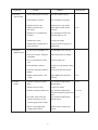
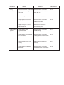
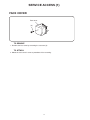
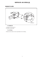
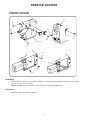
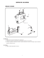
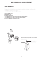
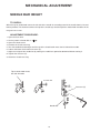
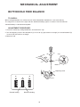
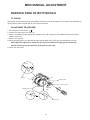
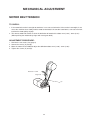
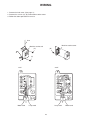
SERVICE MANUAL
MODEL: 13512, 14412, 15312
CONTENTS
TROUBLESHOOTING................................................................................................... 1 - 3
SERVICE ACCESS (1) FACE COVER, BELT COVER...................................................... 4
SERVICE ACCESS (2) BASE PLATE............................................................................... 5
SERVICE ACCESS (3) FRONT COVER........................................................................... 6
SERVICE ACCESS (4) REAR COVER............................................................................. 7
TOP TENSION................................................................................................................... 8
BOBBIN TENSION............................................................................................................. 9
PRESSER BAR HEIGHT AND ALIGNMENT................................................................... 10
NEEDLE SWING.............................................................................................................. 11
NEEDLE DROP................................................................................................................ 12
CLEARANCE BETWEEN NEEDLE AND HOOK (ADJUSTMENT METHOD NO.1)........ 13
CLEARANCE BETWEEN NEEDLE AND HOOK (ADJUSTMENT METHOD NO.2)........ 14
FEED DOG HEIGHT........................................................................................................ 15
NEEDLE BAR HEIGHT.................................................................................................... 16
NEEDLE TIMING TO SHUTTLE....................................................................................... 17
BUTTONHOLE FEED BALANCE..................................................................................... 18
FEED BALANCE ON STRETCH STITCH........................................................................ 19
BARTACK FEED OF BUTTONHOLE............................................................................... 20
DISENGAGEMENT OF CAM FOLLOWER...................................................................... 21
MOTOR BELT TENSION.................................................................................................. 22
WIRING............................................................................................................................ 23
PARTS LIST.............................................................................................................. 24 - 41
TROUBLESHOOTING
PROBLEM
CAUSE REMEDY
REFERENCE
1. Skipping 1. Needle is not inserted Insert the needle properly.
stitches properly.
2. Needle is bent or worn. Change the needle.
3. Incorrectly threaded Rethread.
4. Needle or thread are
Use the recommended sewing
inappropriate for fabric being
needle and thread.
sewn.
5. Sewing on stretch fabric
Use A #11 blue tip needle.
6. Inappropriate needle bar See mechanical adjustment
P. 16
“Needle bar height.”
height 7. Inappropriate needle to hook
See mechanical adjustment
timing
“Needle timing to shuttle.”
P. 17
8. Inappropriate needle to hook clearance See mechanical adjustment
P. 13, 14
“Clearance between needle and
hook.”
2. Fabric not 1. Incorrect feed dog height
See mechanical adjustment
moving
“Feed dog height.”
2. Thread on bottom side of Make sure to bring both needle
fabric is jammed up. and bobbin thread under the foot
when starting sewing.
3. Feed dog teeth are worn.
Change the feed dog.
1
P. 15
PROBLEM
CAUSE REMEDY
REFERENCE
3. Breaking 1. Initial sewing speed is too fast. Start with medium speed.
upper thread
2. Thread path is incorrect. Use the proper thread path.
Replace with a new needle.
3. Needle is bent or dull.
4. Upper thread tension is too strong.
Adjust upper thread tension
correctly.
5. Needle size is inappropriate for fabric. Use appropriate needle and
thread for fabric in use.
6. Needle eye is worn. Change the needle.
7. Needle hole in needle plate is
worn or burred.
Repair the hole or replace the
needle plate.
P. 8
4. Breaking
1. Incorrectly thread bobbin case. Thread bobbin case correctly.
bobbin thread
2. Too much thread is around on
the bobbin.
Adjust the position of stopper.
3. Lint is stuck inside the hook race.
Clean the hook race.
4. Thread quality is too low. Change to a high quality sewing
thread.
Clear out the jamming thread.
5. Thread is jamming around the bobbin.
6. Bobbin thread tension is too
strong.
Adjust bobbin thread tension correctly.
P. 9
5. Needle
breaks
1. Needle is hitting the needle plate. See mechanical adjustment
“Needle drop .”
P. 12
2. Needle is bent or worn. Change the needle.
3. Needle is hitting the hook race. See mechanical adjustment
“Clearance between needle and
hook .”
P. 13, 14
4. The fabric moves while the
needle is piercing it, or the P. 11
See mechanical adjustment
“Needle swing.”
needle zigzags while in fabric.
5. Fabric is being pulled too strongly while sewing.
Guide the fabric gently while
sewing.
2
PROBLEM
6. Noisy
CAUSE REMEDY
1. Backlash between shuttle hook See mechanical adjustment operation gear and lower shaft gear is REFERENCE
P. 14
“Clearance between needle and
too great.
hook (NO. 2).”
2. Lower shaft gear is loose.
Eliminate the looseness.
3. Inappropriate belt tension. See mechanical adjustment P. 22
“Motor belt tension.”
4.Upper shaft gear is loose. Eliminate the looseness.
5. Not enough oil. Oil all moving parts.
7. Deformation of 1. Inappropriate zigzag See mechanical adjustment pattern synchronization.
“Needle swing.”
P. 11
2. Inappropriate disengagement
of cam follower. See mechanical adjustment P. 21
“disengagement of cam follower.”
3. Upper thread tension is too Adjust upper thread tension strong.
P. 8
correctly.
4. Inappropriate feed balance See mechanical adjustment BALANCE
"Feed balance on stretch stitch."
3
P. 19
SERVICE ACCESS (1)
FACE COVER
Face cover
(A)
To remove
1. Remove the face cover by removing the setscrew (A).
To attach
2.Mount the face cover in reverse procedure of the removing.
4
SERVICE ACCESS (2)
BASE PLATE
(A)
Base plate
To remove
1. Remove the setscrews (A).
2.Remove the base plate.
To attach
3.Mount the base plate in reverse procedure of the removing.
5
SERVICE ACCESS
FRONT COVER
(L)
(A)
(G)
(E)
(D)
Cap
Front cover
(F)
(H)
(C)
(B)
(J)
(I)
TO REMOVE:
1. Loosen the set screws (A), (B), and (C), and then, remove the front cover by removing the set screws
(D), (E), (F), (G), (H), (I) and (J).
NOTE: Unhook the tab (L) from the rear cover when remove the front cover.
TO ATTACH:
2. Follow the above procedure in reverse.
6
SERVICE ACCESS
REAR COVER
(A)
(B)
(D)
Rear cover
(F)
(E)
(C)
TO REMOVE:
1. Remove the face cover and front cover. (See page 5)
2. Loosen the setscrews (A), (B) and (C), and remove setscrews (D), (E) and (F).
3. Pull up the spool pins. Remove the machine socket. Remove the rear cover clearing the presser foot lifter
frome the slit on the cover.
TO ATTACH:
4. Follow the above procedure in reverse.
7
MECHANICAL ADJUSTMENT
TOP TENSION
The top tension should be between 65 and 95g when pulling the thread up in the direction of C.
* Use polyester sewing thread #50 (white).
* If it is not within the above limit, adjust as follows
1. Set the tension dial “3”.
2. Remove the cover.
3. Lower the presser foot.
• If the top tension is too loose, turn the lead screw in the direction (A).
• If the top tension is too tight, turn the screw in the direction (B).
4. Check the top tension and attach the cover.
(B)
(A)
Pull the thread at the speed of 110mm/sed in the
direction of arrow
White polyester
thread size 50
8
MECHANICAL ADJUSTMENT
BOBBIN TENSION
To check:
Set the bobbin in the bobbin case and pass the thread (cotton #50) through the tension spring.
The bobbin thread tension should be 45–55g when pulling the thread in the direction of (B).
If the tension is out of the range, adjust it as follows:
Adjustment procedure:
1. Turn the adjusting screw (C) in the direction of (D) when the bobbin thread tension is too tight.
2. Turn the adjusting screw (C) in the direction of (E) when the bobbin thread tension is too loose.
(B)
Cotton thread #50
(E)
(D)
(C)
9
MECHANICAL ADJUSTMENT
PRESSER BAR HEIGHT AND ALIGNMENT
To check:
1.Raise the presser foot lever (A).
2.The distance between the presser foot (D) and the needle plate (E) should be 6.0 mm (0.24").
Adjustment procedure:
1.Remove the face cover (See page 4).
2.Raise the presser foot lever and loosen the setscrew (C) on the presser bar holder.
Adjust the distance between the presser foot (D) and the needle plate (D) to 6.0 mm (0.24").
3.Tighten the setscrew (C) securely.
4.Tighten the setscrew (B) to secure the lamp socket.
5.Attach the face cover.
NOTE: When you tighten the setscrew (B), make sure that both sides of the
presser foot are parallel to the feed dog slots (F) on the needle plate.
(A)
(B)
(C)
(F)
(D)
(E)
6.0 mm
10
MECHANICAL ADJUSTMENT
NEEDLE SWING
To check:
Adjust the needle swing according to the following procedure, If the needle bar starts moving sideways while
the needle is in the fabric when sewing the zigzag pattern (with maximum zigzag width).
Adjustment procedure:
1.Set the pattern selector dial with maximum zigzag width, and remove the front cover (See page 6).
2.Loosen two setscrews.
3.Adjust the needle swing by turning the handwheel, while holding the worm so as not to rotate it, until the
needle swing starts at 2–3 mm above the needle plate after the needle has come out of the right side of the
needle hole.
4.Tighten two setscrews.
5.Mount the front cover.
NOTE: After adjusting the needle swing, check that the upper shaft worm and gear rotate
smoothly without any backlash between them.
Gear
Upper shaft worm
Setscrew
(2 pcs.)
2–3 mm
11
MECHANICAL ADJUSTMENT
NEEDLE DROP
To check:
When the needle swings in maximum zigzag width, the distance between both ends of the needle hole on the
needle plate and the needle drop positions should be equal.
If not, adjust as follows:
Adjustment procedure:
1. Remove the face cover (See page 4).
2. Set the pattern selector dial at maximum zigzag width.
3.Loosen the setscrew.
4. Turn the eccentric pin to adjust the needle drop.
5.Tighten the setscrew.
6.Attach the face cover.
NOTE: Check the hook timing after this adjustment.
Setscrew
Setscrew
Both clearances should be equal
12
MECHANICAL ADJUSTMENT
CLEARANCE BETWEEN NEEDLE AND HOOK
(ADJUSTMENT METHOD NO. 1)
To check:
The clearance between the needle and shuttle race should be –0.05 to +0.10 mm.
If not, adjust as follows:
Adjustment procedure:
1.Remove the face cover (See page 4).
2.Set the pattern select dial at "
".
3. Loosen setscrew (A), and move the needle bar supporter in the direction of the arrows to get a clearance
between –0.05 to +0.10 mm.
* If clearance is too wide, move the needle bar supporter to
direction (B).
* If clearance is too narrow, move the needle bar supporter to
direction (C).
NOTE: After this adjustment, check that the clearance between the needle and needle plate
is more than 0.15 mm as shown in figure (D). If not, adjust the clearance between needle
and shuttle race by using adjustment method NO.2 (see next page). Readjust the clearance
between needle and needle plate more than 0.15 mm.
4.Attach the face cover.
Setscrew (A)
Direction (C)
Direction (B)
Needle bar supporter
–0.05 to +0.10 mm
Figure (D)
Clearance between needle and
needle plate should be at least 0.15 mm or more.
13
MECHANICAL ADJUSTMENT
CLEARANCE BETWEEN NEEDLE AND HOOK
(ADJUSTMENT METHOD NO.2)
To check:
Use this adjustment method NO. 2 if the clearance cannot be adjusted by the method NO.1.
The clearance between the needle and shuttle race should be –0.05 to +0.10 mm.
Adjustment procedure:
1.Set the pattern selector dial at "
".
2.Remove the rear cover (See page 7).
3.Loosen the setscrew (A) on the lower shaft bushing and slide the gear about 0.5 mm to the right to create
some slack between the gears.
4.Lower the needle and loosen the two shuttle race setscrews (B).
Move the shuttle race unit axially either forward or backward to adjust the clearance between the needle and
the shuttle race in the range of –0.05 to +0.10 mm.
5.Set the pattern select dial at " ", turn the handwheel to check if the clearance between the needle and inner
edges of the shuttle race spring at the left and right needle drops are equal.
If not, adjust by turning the shuttle race unit.
6.Tighten the two shuttle race setscrews (B).
7.Loosen the setscrew on the lower shaft bushing and slide the gear back to the original position while adjusting
the backlash.
8.Tighten screw (A) firmly.
9.Attach the rear cover.
NOTE: The rotary play of the tip of the shuttle driver should be less than 0.3 mm and the
lower shaft should turn smoothly.
After the adjustment, check the hook timing.
Setscrew (A)
–0.05 to +0.10 mm
Clearance should be equal
Needle
Shuttle race
setscrews (B) (2 pcs.)
Shuttle race spring
Lower shaft bushing (front)
14
MECHANICAL ADJUSTMENT
FEED DOG HEIGHT
To check:
1.Lower the presser foot.
2.Turn the handwheel toward you to bring the feed dog to its highest position. The height of the feed dog from the
needle plate should be 0.75-0.90mm.
If it is not in the range, adjust as follows.
Adjustment procedure:
1.Open the shuttle cover.
2.Lower the presser foot and turn the handwheel toward you until the feed dog comes to its highest point.
3.Loosen the setscrew (A) .
4.Turn the feed lifting pin to adjust the height of feed dog (0.75-0.90 mm).
5.Tighten the setscrew (A).
6.Turn the handwheel toward you to recheck the height of feed dog.
Needle plate
0.75-0.90 mm
Feed lifting pin
15
MECHANICAL ADJUSTMENT
NEEDLE BAR HEIGHT
To check:
When the tip of shuttle hook meets the left side of the needle in ascending travel of the needle from its left and
lowest position, The distance between the top of the needle eye and the tip of the shuttle hook should be in the
range of 2.9-3.5 mm.
Adjustment procedure:
1.Open the face cover.
2.Set the pattern selector dial at "
".
3.Open the shuttle cover.
4.Remove the shuttle race ring.
5.Turn the handwheel toward you until the tip of the shuttle hook meets the left side of the needle.
6.Loosen the lower shaft crank arm screw (A).
7.Adjust the height of the needle bar by moving the needle bar upward or downward without turning it.
8.Tighten the setscrew (A).
9.Attach the shuttle race ring.
Tip of shuttle hook meets
left side of needle
2.9–3.5 mm
Setscrew (A)
Needle bar
16
MECHANICAL ADJUSTMENT
NEEDLE TIMING TO SHUTTLE
To check:
The height of the needle point from its lowest point of travel should be in the range of 1.45-1.95 mm when the
tip of the shuttle hook just meets the left side of the needle at the left needle position.
Adjustment procedure:
1.
2.
3.
4.
5.
6.
7.
Set the pattern selector dial at "
".
Remove the base (See page 5).
Open the shuttle cover.
Remove the shuttle race ring.
Turn the handwheel toward you until the tip of the shuttle hook meets the left side of the needle.
Loosen the lower shaft crank arm screws (A).
While holding the shuttle hook so it doesn't turn, turn the handwheel toward you until the needle comes to its
lowest position.
Then, further turn the handwheel to raise the needle about 1.7 mm from its lowest position.
8. Tighten the setscrews (A).
9. Turn the handwheel toward you to check if the height is in the range of 1.45-1.95 mm.
If it is not in this range, repeat the above procedure.
10. Attach the shuttle race ring.
11. Attach the base.
1.45-1.95 mm
Lower shaft crank arm
Lowest position
Lower shaft
Setscrews (A) (2 pcs.)
17
MECHANICAL ADJUSTMENT
BUTTONHOLE FEED BALANCE
To check:
When sewing buttonhole, the stitches on each side of buttonhole should be the same stitch density.
The range of 9-12 stitches in the right side row "backward feeding" against 10 stitches in the left side row
"forward feeding" is considered acceptable.
Adjustment procedure:
1.Check the stitches by sewing buttonholes, and remove the cap.
2.Turn the adjusting screw in the direction of (C) in case of (A) (right stitches are rough), or in the direction of (D)
in case of (B) (left stitches are rough).
3.Mount the cap.
(D)
(C)
Cap
Notch
Adjusting screw
A
Forward feeding
B
Backward feeding
18
MECHANICAL ADJUSTMENT
FEED BALANCE ON STRETCH STITCH
To check:
If the stretch stitch patterns are distorted with setting the stitch length dial at " S.S. ".
(In case of being a difference between forward feeding and backward feeding during stretch stitch pattern
sewing), make an adjustment as follows:
Adjustment procedure:
1.Remove the cap.
2. Set the pattern selector dial at " " , and the stitch length dial at "S.S.".
3. Turn the stretch stitch adjusting screw in the direction of (C) when A > B, or in the direction of (D) when A < B.
4.Attach the cap.
(C)
(D)
Cap
Notch
Stretch stitch
adjusting screw
A
A
1
2
A=B
A 1
3
B
A 2
3
A>B
A
1
A
2
3 B
B
A<B
19
MECHANICAL ADJUSTMENT
BARTACK FEED OF BUTTONHOLE
To check:
If the material is fed forward or backward when sewing bartack on buttonhole, make an adjustment as follows:
Adjustment procedure:
1.Set the pattern selector dial at "
", and the stitch length dial at "4".
2. Remove the front cover (See page 6).
3. Place a piece of paper under the foot and turn the handwheel.
If the paper is fed forward, turn the adjusting screw in the direction of (C).
If the paper is fed backward, turn the adjusting screw in the direction of (D).
4.Attach the front cover.
(D)
(C)
Adjusting screw
Stitch length dial
Forward feeding
Backward feeding
20
MECHANICAL ADJUSTMENT
BARTACK FEED OF BUTTONHOLE
To check:
Too narrow clearance between the cam follower and the top convex of zigzag cam may often cause difficulty in
turning of the pattern selector dial, or can not correct pattern.
Adjustment procedure:
1.Set the pattern selector dial "
".
2. Remove the front cover (See page 6).
3. Put the cam follower to the zigzag cam (straight cam), and also put the cam follower releasing arm to the
pattern select cam.
4. Loosen the setscrew.
5. Move adjusting plate in the direction of arrow until to touch to the releasing arm and tighten setscrew.
NOTE: After this adjustment, check that the clearance between the zigzag cam and the cam
follower releasing arm onto position (A) of pattern select cam.
6.Attach the front cover.
0.3mm
ZZ cam
Release arm
Setscrew (A)
Pattern selector cam
Adjusting
plate
Release arm
21
MECHANICAL ADJUSTMENT
MOTOR BELT TENSION
To check:
1. If the motor belt tension is too tight or too loose, it can cause a belt noise: if the tension is too toight, it can
cause the machine to run slowly and the motor to overload; if the tension is too loose; it can cause the belt
teeth on the motor pulley to jump.
2. The correct motor belt tension is when the deflection of motor belt is about 7mm (0.28”) - 9mm (0.36”).
(When pushing the motor belt by finger with a 300 gram load.)
Adjustment procedure:
1. Remove the rear cover. (See page 6)
2. Loosen the screws (A) and (B).
3. Move the motor UP or DOWN to adjust the deflection about 7mm (0.28") - 9mm (0.36").
4. Tighten the screws (A) and (B).
Deflection 7–9 mm
300g Load
(A)
(B)
22
WIRING
1.Remove the belt cover. (See page 4.)
2.Remove the screws (A), (B) and machine socket cover.
3.Follow the above procedure in reverse.
Arm
Machine socket cover
Machine socket unit
(A)
(B)
(A)
120V
Motor cord
240V
Lamp cord
Lamp cord
23
Motor cord