1
Ligação | pt
Plena
Int Booster
Ext
Booster
1 Channel
BGM/Ca
N.C./Spall
re
A
Z1
100V
2 Channel
BGM/Sp
are
Call
B
Override
/Trigger
0
Z2
Output
100V
100V
24V
0
Z3
0
100V
Desig
The n & Qu
Nethe ality
rlands
Z4
100V
Z5
100V
Z6
100V
Z1
Trigger
input/24V
Z1
Emergenc
y
1
2
100V
0
90/0
0
Z2
Z2
0
COM
Z3
Z3
NO
0
NO
Business
1
NO
Fault
1
TRG
out
3
2
4
3
2
NC
COM
Z6
Z5
100V
NO
5
4
3
24V
6 DC
out
5
4
VOX
6 Switch
5
Call
6
24V
10k
10k
24V
DC
out
NC
1
NO
0
NC
COM
COM
Z5
Z4
100V
0
EMG
NC
Z4
100V
0
0
Ext
Booster 100V
In
0
DC
In
24V
DC
NC
100V
0
0
Plena
8900
Max. Voice Ala
199
0000
Ratedoutput po rm Contr
1
we
oll
ou
5-230 tput po r 360W er
S/ N. V~, 50 wer 24
/60H 0W
z
Call
station
Volume
For service
Override
Z6
only
TRG2
100V
70V
Int
Booster
0
Out
SEL1
SEL0
1
2
Out
1
3
4
5
100V
Call
6
VOX
out
2
Switch
Max. Voice Alarm
Ratedoutput power Controlle
output
115-230V
power360W r
S/N.
~, 50/60Hz240W
Monitor
APR
mode
Supervis
2ch
ion
operatio
LBB199
Firmwar
Upgradee
Off
4
In
GND
Design
The & Quality
Netherland
s
n
Impedan
Calibrat ce
ion
External
Booster
230V~
Apparat
Connecus delivere
ted for d
230V~
USB
Fireman
On
's panel
Power
L
Rated
230V
N66
CD/Tun
er
LBB199
GND
Mic/Line
Vox
Appa
ra
Conn tus de
ecte livered
d for
230V
~
power:7
60VA
T10L25 0V for230V
0V for115V AC
AC
Remote
Control
Panel
Vox
Speech
Phantomfilter
power
Off
PC
input
4
Line
fuse
T6.3L25
R
AUX
~
3
USB
115V~
N663
On
Off
115V
~
69
On
1
Router
Digital
Messag
Monitori
ng
Speaker
e
2
Warnin
This
g
apparatus
must
be earthed
Firem
an's
pa
nel
Powe
r
Rate
Phan
tom
d inp
LB B1
994
Line
T6.3 fuse
L2
T10L 50V fo
250V r230
for11 V AC
5V AC
Remo
te Co
ntrol
Pane
l
powe
r
ut po
wer:7
60VA
1
Rout
er
Digit
Mes al M
sage onito
Spea ring
ker
2
W
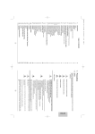
Figura 5.17: Ligar o cabo de alimentação
Alimentação de reserva
O controlador de alarme por voz tem uma entrada de 24 V(dc) para ligar uma fonte de
alimentação de reserva (por ex., uma bateria) que alimenta o sistema no caso de a
alimentação de rede eléctrica não estar disponível. Consulte as informações pormenorizadas
da ligação abaixo:
Int Booster
Ext
Booster
A
Z1
1 Channel
BGM/Ca
N.C./Spall
re
100V
2 Channel
BGM/Sp
are
Call
B
Override
/Trigger
0
Z2
Output
100V
100V
24V
0
Z6
100V
Z3
100V
Z4
100V
0
0
100V
Trigger
input/24V
Z1
Emergenc
y
1
2
Z2
Z2
0
COM
Z3
Z3
NO
0
COM
NO
0
TRG
COM
NO
0
NO
Business
1
2
COM
1
2
out
3
4
3
5
4
3
24V
6
10k
10k
24V
DC
out
Call
station
For service
Override
only
TRG2
Int
Booster
1
Out
Out
Call
Ext
VOX
6 Switch
5
Volume
Z6
SEL1
SEL0
2
1
3
4
5
100V
6
VOX
out
2
Switch
Firmwar
Upgradee
Off
Max. Voice Alarm
Ratedoutput power Controlle
output
115-230V
power360W r
S/N.
~, 50/60Hz240W
Monitor
APR
mode
Supervis
2ch
ion
operatio
LBB199
4
In
GND
0
24V
6 DC
out
5
4
Call
NC
1
NO
0
100V
70V
NC
NC
Z6
Z5
100V
Fault
Z5
Z4
100V
0
Ext
Booster 100V
In
0
DC
In
24V
EMG
NC
Z4
100V
0
DC
NC
100V
0
100V
Z6
Z1
100V
0
Z5
Design
The & Quality
Netherland
n
Off
Impedan
Calibrat ce
ion
Booster
230V~
Apparat
Connecus delivere
ted for d
230V~
USB
Fireman
On
's panel
Power
L
Rated
CD/Tun
GND
er
Line
fuse
T6.3L25
R
AUX
PC
Mic/Line
100V
In
115V~
N663
s
On
External
Vox
LBB199
4
input
power:7
60VA
T10L25 0V for230V
0V for115V
AC
AC
Remote
Control
Panel
Vox
Speech
Phantomfilter
power
Off
On
1
Router
Digital
Messag
e
Monitori
ng
Speaker
2
Warnin
This
g
apparatus
must
be earthed
0
DC
In
24V
Charger
24
+
VDC
Figura 5.18: Ligar uma fonte de alimentação de reserva
Bosch Security Systems B.V.
Installation and Operation manual
2013.07 | V2.0 |