1
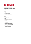
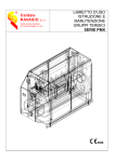
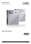
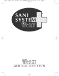
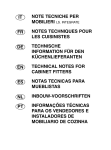
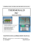
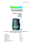
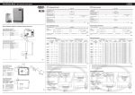
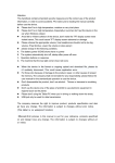
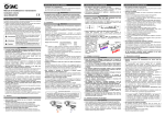
+040000040 - rel. 1.1 - 16.12.2014
mc multizone -
quick guide
Caratteristiche
linea acqua
portata max (l/h, lb/h,
G/d)
pressione ingresso
(Mpa,Bar,PSI)
temperatura
ingresso
uscita
scarico
Caratteristiche
linea aria
Fig. 1
10
9
AIM 29 -DIN 74324
NPT1/4”F
NPT1/2”F
NPT1/4”F
descrizione
filtro olio 3/8” x aria
filtro aria 1/2”
contenitore filtro acqua 5”
kit sanificatore a raggi uv
trasduttore di pressione
manometro aria uscita 0...4 bar
elettrovalvola NA fine linea
manometro acqua uscita 0...2,5 bar
attacchi
G3/8”f in /out
G1/2”f in /out
G1/2”f in /out
G1/4”f in /out
G1/4”m
G1/4”m
G1/4”f in /out
G1/4”m
MC***CD*01
230 V; 1; 50 Hz
44 W
0,29 A
Characteristics
of the air line
MC230*1*0*
NPT1/2”F
NPT1/2”F
Water and air
line accessories
riferimento in fig. 2
2
3
4
5
10 a
10 b
13
14
MC***HD*00
230 V; 1; 50/60 Hz
41 W
0,30 A
MC060*D*0*
MC***HD*01
230 V; 1; 50 Hz
48 W
0,33 A
37 W
0.26 A
MC230*1*0*
1 to 50 ºC / 34 to 122 ºF
NPT1/2”F
G1/2”F
NPT1/2”F
G1/2”F
description
3/8” oil filter for air
1/2” air filter
5” water filter container
UV santising kit
pressure traqnsducer
air outlet pressure gauge 0 to 4 bars
NO solenoid valve at end of line
water outlet pressure gauge 0 to 2.5 bars
Power
Current
(1)
NPT1/4”F
NPT1/2”F
NPT1/4”F
Models
MC060*1*0*
MC230*D*0*
0.5 to 0.7 Mpa; 5 to 7 Bar; 80 to 100 PSI
G1/2”F
G1/2”F
Models MC****D*** (230 V 50 Hz)(1)
MC***CD*00
Electrical
Vac; fasi; Hz
230 V; 1; 50/60 Hz
specifications
MC230*1*0*
230 l/h, 500 lb/h,
1450 G/d
1 to 50 ºC / 34 to 122 ºF
NPT1/4”F
G1/2”F
NPT1/2”F
G1/2”F
NPT1/4”F
TCF 8/10
G1/2”F
G1/2”F
TCF 8/10
inlet pressure
(Mpa,Bar,PSI)
temperature
inlet
outlet
code
MCFILOIL01
MCFILAIR01
MCFILWAT05
MCKSUV0000
MCKPT**000
MCKMA04000
MCKDVWL00*
MCKMW02501
Models
MC060*1*0*
MC230*D*0*
60 l/h, 130 lb/h,
230 l/h, 500 lb/h,
130 lb/h
1450 G/d
0.3 to 0.7 Mpa; 3 to 7 Bar; 40 to 100 PSI
fittings
G3/8”f in /out
G1/2”f in /out
G1/2”f in /out
G1/4”f in /out
G1/4”m
G1/4”m
G1/4”f in /out
G1/4”m
MC***CD*01
230 V; 1; 50 Hz
44 W
0.29 A
NPT1/2”F
NPT1/2”F
refernce in fig. 2
2
3
4
5
10 a
10 b
13
14
MC***HD*00
230 V; 1; 50/60 Hz
41 W
0.30 A
MC***HD*01
230 V; 1; 50 Hz
48 W
0.33 A
Product in compliance with EN55014, EN61000, EN60335
--RILSAN
Potenza
Corrente
Cabinet MC
L
N
GR
Air
1
6
3
Cabinet MC
J24
GND
J2
B1
6
1
Cabinet MC
7
4
J24
Attenzione: prima di procedere assicurarsi che l’umidificatore non sia collegato alla rete elettrica.
Warning: before proceeding, disconnec the humidifier from the power supply
J11
J2
Fig. 2
+V term
GND
B1
B2
Cabinet MC
C8
C7
J14
NC8
NO8
C4
C7
NO6
NO7
C1
C4
NO5
NO4
C1
NO3
NO2
NO1
GND
Rx+/Tx+
Rx-/Tx-
J9
J13
Cavo alimentazione
L/F (fase)
N/W (neutro)
GR/PE (terra)
sonda umidità
limite
+(G)
M
out H
J2
J15
IDC1
ID8
ID7
ID6
ID5
ID4
ID3
ID2
ID1
Y4
Y3
Y2
Y1
VG0
VG
+V term
GND
B1
B2
J24
J5
J4
BC5
B5
BC4
B4
+VDC
NL
ser i al c ard
J3
GND
B3
B2
J2
B1
J24
+5V ref
field c ard
GND
+V term
input: 24 V / V ; 50 to 60 Hz
max. power: 40 VA / 15 W
J2
J24 J2
J4
GR
1
ON
0
Cabinet MC
B3
J2
GR
+ VDC
regolatore
esterno
REF
OUT
-
Cabinet MC
Fig. 3
Cabinet MC
NO5
C4
GR
+V term
GND
B1
B2
J24
J2
sonda umid.
limite
sonda umid.
ambiente
+(G)
M
out H
+(G)
M
out H
-
Sonda temperatura
ambiente e umidità limite
+(G)
M
out t
out H
Cabinet MC
+V term
GND
B1
B2
J24
J2
MC Cabinet
L
N
GR
MC Cabinet
J24
GND
J2
B1
sonda umidità ambiente
+(G)
M
Collegamento sonda combinata di temperatura e umidità
limite
MC Cabinet
J24
J2
MC Cabinet
J24
J2
MC Cabinet
umidostato ON/OFF
J24
+(G)
M
out T
-
ID2
COM1
GR
ON/OFF
COM
schermo
J2
Uscita
ON/OFF
COM
schermo
(*)
elettrovalvola
1
2
4
Contatto relè di allarme
(*)
Cabinet MC
C07
N07
GR
J14
(*) Caratteristiche elettriche dei contatti: 500 VA; 250 V; 2 A induttivi/resistivi
Uscita
COM
ON/OFF
schermo
+V term
GND
B1
B2
48 W
0.70 A
MC Cabinet
ID1
COM (1 o 2 o 3)
GR
external controller
REF, schermo
OUT
limit humidity
probe
+(G)
M
out H
external
controller
REF
OUT
-
Ambient temperature and limit
humidity probe
+(G)
M
out T
Temperature probe + limit humidity probe connetion
Cabinet MC
Cabinet MC
G0
NO4
GR
+V term
GND
B1
MC***H1*01
Remote ON/OFF (ID & COM)
Power cable
L/F (Phase)
N/W (neutral)
GR/PE (earth)
Temperature probe connection
Collegamento umidostato ON/OFF
Collegamento elettrovalvola scarico fine linea acqua
+V term
GND
B1
B2
MC***H1*00
110 V; 1; 60 Hz
41 W
0.64 A
Product approved to UL998 & CSA C22.2 No104
Modulating control with controller and limit probe
(2) sonda temperatura
Comando per attivazione compressore e/o WTS
J13
(1)
ON/OFF remoto
NC/NO
C
schermo
Collegamento sonda umidità e sonda umidità limite
sonda pressione
C
A
44 W
0.60 A
Modulating control with external controller
+(G)
M
out T
cavo
bianco
schermo
nero
Cabinet MC
+V term
J24
GND
Collegamento sonda di pressione fine linea aria
37 W
0.54 A
Power
Current
48 W
0,70 A
Collegamento sonda umidità
Sonda temperatura ambiente
(1) sonda
umid. limite
+(G)
M
out H
MC***C1*01
Power supply
Collegamento sonda di temperatura + sonda umidità limite
Cabinet MC
MC***C1*00
Collegamento ON/OFF remoto (ID e COM)
ser vice c ard
J1 0
Models MC****1*** (110 V 60 Hz)(1)
Electrical
Vac; fasi; Hz
specifications
MC***H1*01
Cabinet MC
ID1
COM (1 o 2 o 3)
GR
regolatore esterno
REF, schermo
OUT
+V term
GND
B1
J24
J12
MC***H1*00
110 V; 1; 60 Hz
41 W
0,64 A
Prodotto omologato UL998 e CSA C22.2 No104
Collegamento sonda di temperatura
J13 J14
J11
44 W
0,60 A
Collegamento regolatore modulante con sonda
umidità limite
5
J10
MC***C1*01
Collegamento regolatore modulante esterno
Water
2
(1)
Alimentazione elettrica
MC***C1*00
37 W
0,54 A
11
G0
NPT1/4”F
NPT1/2”F
NPT1/4”F
Prodotto in conformità con EN55014, EN61000, EN60335
Modelli MC****1*** (110 V 60 Hz)
Caratteristiche
Vac; fasi; Hz
elettriche
14
G
1...50 ºC / 34...122 ºF
G1/2”F
G1/2”F
TCF 8/10
MC060*D*0*
60 l/h, 130 lb/h,
380G/d
(l/h, lb/h, G/d)
inlet pressure
(Mpa,Bar,PSI)
temperature
inlet
outlet
drain
(1)
13
J1
230 l/h, 500 lb/h,
1450 G/d
1...50 ºC / 34...122 ºF
NPT1/2”F
G1/2”F
NPT1/2”F
G1/2”F
G1/2”F
G1/2”F
Characteristics
of the water
max flow-rate
line
MC230*1*0*
Modelli
MC060*1*0*
MC230*D*0*
0,5...0,7 Mpa; 5...7 Bar; 80...100 PSI
MC060*D*0*
37 W
0,26 A
(1)
PA11 O 6
8x6
DIN 74324
AIM 29 --
PA11 O 6
8x6
--RILSAN
13
J9
G1/2”F
G1/2”F
TCF 8/10
Potenza
Corrente
DIN 74324
PA11 O 6
8x6
--RILSAN
8
MC230*D*0*
60 l/h, 130 lb/h,
230 l/h, 500 lb/h,
130 lb/h
1450 G/d
0,3...0,7 Mpa; 3...7 Bar; 40...100 PSI
Modelli MC****D*** (230 V 50 Hz)(1)
MC***CD*00
Caratteristiche
Vac; fasi; Hz
230 V; 1; 50/60 Hz
elettriche
AIM 29 --
12
codice
MCFILOIL01
MCFILAIR01
MCFILWAT05
MCKSUV0000
MCKPT**000
MCKMA04000
MCKDVWL00*
MCKMW02501
MC060*1*0*
60 l/h, 130 lb/h,
380G/d
pressione ingresso
(Mpa,Bar,PSI)
temperatura
ingresso
uscita
Caratteristiche
accessori linee
acqua e aria
Modelli
MC060*D*0*
(1) limit hum.
probe
+(G)
M
out H
(2) temperature
probe
+(G)
M
out T
-
Remote ON/OFF
NC/NO
C
Sh
Ambient humidity probe connection
MC Cabinet
+V term
GND
J24
ambient humidity probe
+(G)
M
Ambient probe and limit probe connection
MC Cabinet
J24
J2
+V term
GND
B1
B2
limit humidity
probe
+(G)
M
out H
ambient humidity
probe
+(G)
M
out H
-
Ambient temperature and limit humidity probe
connection
MC Cabinet
J24
J2
+V term
GND
B1
B2
Ambient temperature and limit
humidity probe
+(G)
M
out t
out H
ON/OFF humidistat connection
MC Cabinet
ON/OFF humidistat
ID2
COM1
GR
ON/OFF
COM
shield
Connection of pressure probe at end of air line
Connection of drain valve at end of water line
Start compressor and/or WTS(*) control
Cumulative alarm relay(*)
MC Cabinet
B3
J2
GR
+ VDC
Cabinet MC
NO5
J13
C4
GR
cable
white
shield
black
pressure probe
C
A
Output
ON/OFF
COM
shield
MC Cabinet
G0
NO4
GR
MC Cabinet
C07
J14
N07
GR
*) Electrical specifications of the relay: power 500 VA; voltage 250 V; current 2 A restitive/inductive
solenoid valve
1
2
4
Output
COM
ON/OFF
shield
Ingressi allarme da dispositivi esterni
GR
GR
J14
J9
Cabinet MC
C1
C8
NC8
NO8
GND
Rx+/Tx+
C7
NO7
Rx-/TxC7
C4
NO6
C4
NO5
NO4
C1
NO3
J13
ID7
COM1
J 1J11
5
BC5
B5
BC4
B4
+VDC
J3
GND
IDC1
B3
ID8
B2
ID7
B1
J2
ID6
ID2
+V term
ID3
GND
ID4
+5V ref
ID5
J24 J5
ID1
J1
Y3
G
Y4
G0
Y2
Y1
VG0
VG
J4
BC5
B5
BC4
B4
+VDC
J3
GND
B3
B2
B1
+5V ref
J2
f i el d c ard
Fig. 4
pLAN network connection (J11)
MC Master cabinet J11
RX+/TX+
J11
RX-/TXGND
MC Slave cabinet
RX+/TX+
J11
RX-/TXGND
Utilizzare cavi bipolari più terra AWG 20/22, distanza massima tra due cabinet: 200m (219 yd).
In modalità multizone, disattivando la funzione “stop slave off line”, in caso di interruzione pLan le unità slave funzionano autonomamente secondo i segnali provenienti dalle sonde o/e regolatori. In questa modalità i valori non
verranno visualizzati dal display del master.
Use two-wire cables plus earth, AWG 20/22, maximum distance between two cabinets: 200 m (219 yd). In multizone mode, by
disabling the “stop slave off line” function, if the pLAN is interrupted the slaves operate independently according to the signals
from the probes or/and controllers. In this mode, the values will not be shown on the master display.
AVVERTENZE IMPORTANTI
PRIMA DI INSTALLARE O MANEGGIARE IL DISPOSITIVO, LEGGERE ATTENTAMENTE E SEGUIRE LE ISTRUZIONI E LE NORME PER LA SICUREZZA DESCRITTE
NEL PRESENTE MANUALE ED ILLUSTRATE SULLE TARGHETTE APPLICATE SUL DISPOSITIVO.
L’installazione, uso e manutenzione siano effettuate in conformità con le istruzioni fornite nel presente manuale e con le normative legali vigenti. Ogni
altro uso del dispositivo e modifica effettuata sull’unità senza l’autorizzazione di CAREL S.p.A. sono considerati impropri. Le condizioni ambientali e
l’alimentazione devono essere conformi alle indicazioni specificate. Togliere l’alimentazione prima di intervenire direttamente sulle le parti interne del
prodotto. La responsabilità degli eventuali danni a cose o persone dovuti ad un uso improprio del dispositivo ricadrà esclusivamente sull’utente. Si prega
di tener presente che l’unità contiene dispositivi alimentati elettricamente e componenti ad alta pressione. Tutte le operazioni legate al funzionamento
e/o alla manutenzione dell’unità devono essere effettuate da personale esperto e qualificato a conoscenza delle necessarie precauzioni.
Smaltimento delle parti dell’umidificatore: l’umidificatore è composto da parti in metallo e da parti in plastica.
In riferimento alla Direttiva 2002/96/CE del Parlamento Europeo e del Consiglio del 27 gennaio 2003 e alle relative normative nazionali di attuazione, Vi
informiamo che:
1.
sussiste l’obbligo di non smaltire i RAEE come rifiuti urbani e di effettuare, per detti rifiuti, una raccolta separata;
2.
per lo smaltimento vanno utilizzati i sistemi di raccolta pubblici o privati previsti dalla leggi locali. È inoltre possibile riconsegnare al
distributore l’apparecchiatura a fine vita in caso di acquisto di una nuova.
3. questa apparecchiatura può contenere sostanze pericolose: un uso improprio o uno smaltimento non corretto potrebbe avere effetti negativi sulla
salute umana e sull’ambiente;
4. il simbolo (contenitore di spazzatura su ruote barrato) riportato sul prodotto o sulla confezione e sul foglio istruzioni indica che l’apparecchiatura è
stata immessa sul mercato dopo il 13 Agosto 2005 e che deve essere oggetto di raccolta separata;
5. in caso di smaltimento abusivo dei rifiuti elettrici ed elettronici sono previste sanzioni stabilite dalle vigenti normative locali in materia di
smaltimento.
Garanzia sui materiali: 2 anni (dalla data di produzione).
Omologazioni: la qualità e la sicurezza dei prodotti CAREL sono garantite dal sistema di progettazione e produzione certificato ISO 9001, nonché
dal marchio
.
IMPORTANT WARNINGS
BEFORE INSTALLING OR HANDLING THE APPLIANCE PLEASE CAREFULLY READ AND FOLLOW THE INSTRUCTIONS AND SAFETY STANDARDS DESCRIBED IN
THIS MANUAL AND ILLUSTRATED BY THE LABELS ON THE MACHINE.
The installation, operation and maintenance operations must be performed in compliance with the instructions provided in this manual and the
legislation in force. All other uses and modifications made to the appliance that are not authorised by CAREL S.p.A. are considered incorrect .The
conditions of the environment and the power supply voltage must comply with the specified values.The unit must be installed according to the standards
in force regarding the product.Liability for injury or damage caused by the incorrect use of the appliance lies exclusively with the user.Please note that
the unit contains live electrical devices and high pressure components.All service and/or maintenance operations must be performed by specialist and
qualified personnel who are aware of the necessary precautions.
Disposing of the parts of the humidifier: the humidifier is made up of metal and plastic parts.
In reference to European Union directive 2002/96/EC issued on 27 January 2003 and the related national legislation, please note that:
3.
4.
5.
1.
WEEE cannot be disposed of as municipal waste and such waste must be collected and disposed of separately;
2.
the public or private waste collection systems defined by local legislation must be used. In addition, the equipment can be returned to the
distributor at the end of its working life when buying new equipment.
the equipment may contain hazardous substances: the improper use or incorrect disposal of such may have negative effects on human health and
on the environment;
the symbol (crossed-out wheeled bin) shown on the product or on the packaging and on the instruction sheet indicates that the equipment has
been introduced onto the market after 13 August 2005 and that it must be disposed of separately;
in the event of illegal disposal of electrical and electronic waste, the penalties are specified by local waste disposal legislation.
Warranty on materials: 2 years (from the date of production).
Certification: The quality and safety of CAREL products are guaranteed by the Carel ISO 9001 certified design and production system, as well as the
mark.
L’installazione del prodotto deve obbligatoriamente comprendere la connessione di messa a terra, usando l’apposito morsetto giallo-verde in
morsettiera. Non utilizzare il neutro come connessione a terra. / The product must be installed with the earthconnected, using the special
yellow-green terminal on the terminal block. Do not use the neutral for the earth connection.
CAREL INDUSTRIES HQs
Via dell’Industria, 11 - 35020 Brugine - Padova (Italy) - Tel. (+39) 0499716611
Fax (+39) 0499716600 - e-mail: [email protected] - www.carel.com
Relay
ON/OFF
Alarm relay from water treatment
COM
ON/OFF
Compressor alarm relay
COM
ON/OFF
Air flow switch alarm raly
COM
shield
External contact for activating the ash function
Uscita proporzionale 0...10 Vdc
Relè di attivazione lavaggio
esterno
ON/OFF
COM
Cabinet MC
Uscite
MC Cabinet
VG0
Y1
RIF.
0...10 Vdc
ID7
COM1
Relay fro activating wash on
external signal
ON/OFF
COM
Caratteristiche uscita: carico massimo 1 kΩ (10 mA)
Configurazione
Parametri di configurazione Menù Installatore
input: 24 V / V ; 50 to 60 Hz
J24
MC Cabinet
ID3
COM1
ID4
COM1
ID6
COM2
GR
ON/OFF
Relè allarme da trattamento acqua
COM
ON/OFF
Relè allarme compressore
COM
ON/OFF
Relè allarme flussostato aria
COM
schermo
s er v i c e c ard
J10
VA / 15 W
se rmax.
i apower:
l ca40rd
f i e l d ca rd
GND
+V term
G0
G
J12
se r vi ce ca rd
J10
input: 24 V / V ; 50 to 60 Hz
max. power: 40 VA / 15 W
J1
NO2
C1
J11
Alarm input from external devices
Relè
Contatto di attivazione lavaggio linea acqua
SLAVE
NO1
GND
Rx-/Tx-
Rx+/Tx+
MASTER
J9
Cabinet MC
ID3
COM1
ID4
COM1
ID6
COM2
GR
Proportional 0 to10 Vdc output
MC Cabinet
Outputs
VG0
Y1
RIF.
0...10 Vdc
Output specifications: maximun load 1 kΩ (10 mA)
Configuration
Installer menu configuration parameters
Dalla maschera principale premere:
•
PROG per accedere al menu principale;
•
DOWN per posizionarsi sul menu installatore;
•
ENTER per posizionarsi nella password;
•
UP/DOWN per inserire la password “77“
•
ENTER per accedere al menù selezionato;
•
UP/DOWN per spostarsi tra i sottomenù;
•
ENTER per selezionare il parametro e spostarsi tra i parametri;
•
UP/DOWN per modificare il parametro;
•
ENTER per confermare il parametro selezionato e andare al parametro successivo;
•
ESC per ritornare al menù precedente.
From the main screen press:
•
PROG to access the main menu;
•
DOWN to move to the installer menu;
•
ENTER to move to the password;
•
UP/DOWN to enter the password “77“
•
ENTER to access the selected menu;
•
UP/DOWN to move between the submenus;
•
ENTER to select the paramenter and move between the parameters;
•
UP/DOWN to modify the parameter;
•
ENTER to confirm the selected parameter and go to the next parameter;
•
ESC to return to the previous menu.
Maschere del menu installatore:
Installer menu screens: 1. Type of control
1. Tipo regolazione
2. Configurazione sonde
3.
4.
5.
6.
7.
2. Probe configuration
Opzioni funzionali
Funzioni speciali
Supervisione
Allarmi esterni
Configurazione pLAN
Per navigare all’interno della maschere:
• UP o DOWN per modificare il valore (all’interno delle opzioni/range),
• ENTER per confermare e spostare il cursore al valore successivo
• ESC per tornare al menu installatore.
3. Operating options
4. Special functions
5. Supervisor
6. External alarm
7. pLAN configuration
To navigate inside the screens:
• UP or DOWN to change the value (within the options/range)
• ENTER to confirm and move the cursors to the next value
• ESC to return to the installer menu.
Tipo di regolazione
Type of control
Impostazioni: tipo di funzionamento (ON/OFF o modulante), tipo di segnale o sonda, sonda principale, sonda limite, unità di misura
e stop slave offline.
Settings: type of operation (ON/OFF or modulating), type of signal or probe, main probe, limit probe, unit of measurement & stop
slave offline.
parametro
Tipo di
funzionamento
Tipo di segnale o sonda
parameter
Type of operation
Sonda principale
Sonda limite
Unità di misura
stop slave offline
options/range
ON/OFF
modulating
Type of signal or probe External contact
External proportional signal
External proportional signal and linit probe
Humidity probe
Humidity probe and limit probe
Temperature probe
Temperature probe and limit probe
MAin probe
Select between: NTC; 0-1 V; 2-10 V; 0-10 V (default); 0-20 mA; 4-20 mA; 0-135 ohm; 135-1 kohm
Limit probe
°C - bar (default)
Unit of measurament
°F - psi
SI default
if the pLAN netwaork is offline the slave units stop
Stop slave offline
NO
if the pLAN netwaork is offline the slave units continue
opzioni/range
ON/OFF
modulante
Contatto esterno
Segnale proporzionale esterno
Segnale proporzionale esterno e sonda limite
Sonda umidità
Sonda umidità e sonda limite
Sonda di temperatura
Sonda di temperatura e sonda limite
scegliere tra: NTC; 0-1 V; 2-10 V; 0-10 V (default); 0-20 mA; 4-20 mA; 0-135 ohm; 135-1 kohm
°C - bar (default)
°F - psi
SI default
NO
parametro
Opzioni
funzionali Sensore P remoto
max. pressione aria
min. pressione aria
offset max pres. aria
offset min pres aria
valvola fine linea
logica relè allarmi
setpoint segnale proporzion:
se la rete pLAN è offline le unità slave si fermano
se la rete pLAN è offline le unità slave continuano
descrizione
sensore di pressione di fine linea per autobilanciamento impianto aria compressa
per permettere lo svuotamente automatico
e il lavaggio periodico della linea acqua
impostazione stato relè allarmi
range
SI/NO
default
NO
U.M.
0...4
0...4
0...9.9
0...9.9
SI/NO
2,1
1,2
0
0
SI
bar
bar
NA/NC
3...60
NA
10
%
max. air pressure
min. air pressure
max air press. offset
min air press. offset
valve at end of line
logic alarm relay
prop. signal set point:
description
pressure sensor at end of line for balancing
compressed air system
to allow automatic emptying and periodical
washing of the water line
alarm relay status setting
range
YES/NO
default
NO
U.M.
0 to 4
0 to 4
0 to 9.9
0 to 9.9
YES/NO
2.1
1.2
0
0
YES
bar
bar
NO/NC
3 to 60
NO
10
%
Special functions
Funzioni speciali
pulizia automatica: Cicli di autopulizia degli ugelli per
ridurre frequenza di manutenzione
parametro
range
default
U.M.
SI/NO
SI
Abilitata
0....999
30
min
Periodo
60...999
160
s
Durata
Operating parameter
Remote P sensor
options
Lavaggio: lavaggio automatico periodico linea acqua per
aumentare l’igienicità dell’impianto
parametro
range
default
U.M.
man./autom.
man.
lavaggio
NO/SI
NO
inizio lavaggio
1...99
6
h
Periodo lavaggio
0...15
10
min
durata lavaggio
NO/SI
NO
abilita riempimento
1...1000
5
s
durata riempimento
parametro
range
% segnale; Ore; %rH; °C/°F
selezione visualizzazione maschera principale
italiano, inglese, francese, tedesco, spagnolo
Lingua
SI/NO
Mostra scelta della lingua all’accensione?
default
%rH
SI
U.M.
Automatic cleaning: Nozzle self-clean cycles to reduce
the frequency of maintenance
parameter
range
default
U.M.
YES/NO
YES
Enabled
0 to 999
30
min
Period
60 to 999
160
s
Duration
parameter
select display on main screen
Language
Show language choice at start-up?
Washing: Automatic periodical washing of the water line to
increase the hygiene of the installation
parameter
range
default
U.M.
man./autom.
man.
washing
NO/YES
NO
start washing
1 to 99
6
h
washing period
0 to 15
10
min
washing duration
NO/YES
NO
enable filling
1 to 1000
5
s
filling duration
range
% signal; Hours; %rH; °C/°F
italian, English, French, German, Spanish
YES/NO
default
%rH
U.M.
YES
+040000040 - rel. 1.1 - 16.12.2014