1
All rights reserved © WAMGROUP
RVS/RVC
•
BLOW-THROUGH ROTARY VALVES
•
DURCHBLASSCHLEUSEN
•
VANNES ALVEOLAIRES A PASSAGE TANGENTIEL
•
ROTOVALVOLE A FLUSSO ATTRAVERSATO
CATALOGUE No.
TO.310EX
CREATION DATE
ISSUE
CIRCULATION
DATE OF LATEST UPDATE
A2
100
03.07
12 - 2004
All the products described in
this catalogue are manufactured
according to TOREX S.p.A.
Quality System procedures.
Alle in diesem Katalog beschriebenen Erzeugnisse werden in
Konformität mit dem Qualitätssystem der TOREX S.p.A.
hergestellt.
Tous les produits décrits dans
ce catalogue ont été réalisé selon les modalités opérationnelles définies Système de Qualité de TOREX S.p.A.
Tutti i prodotti descritti in questo
catalogo sono stati realizzati secondo modalità operative definite Sistema Qualità di TOREX
S.p.A.
The Company’s Quality System,
starting from the processing of
the order to the technical service after delivery, is carried out
in a controlled manner that guarantees the quality standard of
the product.
Das im Juli 1994 zertifizierte
Qualitätssystem entspricht der
Norm UNI EN ISO 9002-94 (im
Oktober 2002 auf UNI EN ISO
9001-2000 erweitert) und gewährleistet dem Kunden eine
strenge Qualitätskontrolle in jeder Phase des Produktionprozesses bis hin zum Kundendienst nach Auslieferung der
Ware.
Le système de Qualité de l’entreprise, est en mesure d’assurer que le procédé entier de production, à partir de la formulation de la commande jusqu’au
service technique après la livraison, soit effectué de manière
contrôlée et appropriée afin de
garantir le standard de qualité
du produit.
Il Sistema Qualità aziendale, certificato nel Luglio 2004 in conformità con le normative internazionali ISO 9001:2000 è in
grado di assicurare che l’intero
processo produttivo, dalla formulazione dell’ordine fino all’assistenza tecnica successiva
alla consegna, venga effettuato in modo controllato ed adeguato a garantire lo standard
qualitativo del prodotto.
Possible deviations due to modifications and/or manufacturing
tolerances are reserved.
Abweichungen infolge Änderungen und/oder aufgrund von
Fertigungstoleranzen sind vorbehalten.
Nous nous réservons des écartements éventuels dûs des modifications et/ou des tolérances
d’usinage.
Ci riserviamo eventuali scostamenti dovuti a modifiche e/o tolleranze di lavorazione.
03.07
- INDEX
RVS • RVC
- INHALTSVERZEICHNIS
- INDEX
TO.310EX INDEX
- INDICE
1 TECHNICAL CATALOGUE
TECHNISCHER KATALOG
DESCRIPTION.................................................................................
GENERAL DIAGRAM........................................................................
TECHNICAL DATA............................................................................
FINISHING......................................................................................
COLOURS.......................................................................................
ORDER CODES...............................................................................
TOP AND BOTTOM FLANGE..............................................................
PIPE CONNECTION.........................................................................
SIMPLE STEM VALVES......................................................................
VALVES WITH GEAR MOTOR............................................................
VALVES WITH VARIABLE SPEED MOTOR...........................................
DIMENSIONS..................................................................................
AIR OUTLET....................................................................................
DRIVE UNIT DATA............................................................................
BESCHREIBUNG........................................................................
T. .01
GERÄTEAUFBAU..........................................................................02
TECHNISCHE DATEN....................................................................03 →.05
FINISH......................................................................................06
FARBTÖNE...................................................................................07
BESTELLCODES.........................................................................08
OBERER UND UNTERER FLANSCH............................................09
ROHRLEITUNGSVERBINDUNG....................................................10
ZELLENDRADSCHLEUSEN MIT FREIEM WELLENZAPFEN..............11
ZELLENDRADSCHLEUSEN MIT ANTRIEB.....................................12
ZELLENDRADSCHLEUSEN MIT MECHANISCHEM REGELANTRIEB..13
PLATZBEDARF......................................................................... .14
LUFTAUSLASS...........................................................................15
ANTRIEBSDATEN..................................................................... .16
CATALOGUE TECNIQUE
CATALOGO TECNICO
DESCRIPTION.................................................................................
SCHEMA GENERAL.........................................................................
DONNEES TECHNIQUES.................................................................
FINITION........................................................................................
TONALITES.....................................................................................
CODES DE SELECTION...................................................................
BRIDE SUPERIEURE ET INFERIEURE..............................................
RACCORDEMENT TUBE..................................................................
VANNES A ARBRE NU.....................................................................
VANNES MOTORISÉES....................................................................
VANNES AVEC MOTOVARIATEUR MECANIQUE..................................
ENCOMBREMENTS..........................................................................
SORTIE D’AIR.................................................................................
CARACTERISTIQUES MOTORISATION..............................................
DESCRIZIONE..............................................................................
T. .01
SCHEMA GENERALE................................................................... .02
DATI TECNICI...............................................................................03 →.05
FINITURA.....................................................................................06
TONALITÁ.....................................................................................07
CODICI DI SCELTA........................................................................08
FLANGIATURE SUPERIORE E INFERIORE......................................09
IMBOCCHI....................................................................................10
VALVOLE AD ALBERO NUDO..........................................................11
VALVOLE MOTORIZZATE............................................................... .12
VALVOLE MOTORIZZATE CON MOTOVARIATORE DI GIRI..................13
INGOMBRI....................................................................................14
SCARICHI D’ARIA.........................................................................15
DATI MOTORIZZAZIONE............................................................... .16
1
03.07
- INDEX
RVS • RVC
- INHALTSVERZEICHNIS
- INDEX
TO.310EX INDEX
- INDICE
2 MAINTENANCE CATALOGUE
2
DESCRIPTION..............................................................................
MANUFACTURING DATA................................................................
SCOPE AND IMPORTANCE OF MANUAL..........................................
WARNINGS...................................................................................
INDICATIONS FOR THE USE..........................................................
OPERATING CONDITIONS..............................................................
SPECIAL FEATURES......................................................................
ATEX-CERTIFICATION OF THE ROTARY VALVE.................................
WARRANTY CONDITIONS.............................................................
TRANSPORT - DIMENSIONS - WEIGHTS..........................................
WEIGHTS.....................................................................................
PACKAGING.................................................................................
STORAGE.....................................................................................
LIFTING........................................................................................
INSTALLATION..............................................................................
GENERAL PRECAUTIONS..............................................................
COMPRESSED AIR REQUISITES....................................................
START UP PROCEDURE - SHUT DOWN PROCEDURE......................
CONNECTION...........................................................
1ELECTRICAL
OPERATIONS AND MAINTENANCE.................................................
PERIODICAL CHECKS..................................................................
CLEANING....................................................................................
RESIDUAL RISKS..........................................................................
FAULT FINDING............................................................................
SCRAPPING THE MACHINE - RETURNING THE MACHINE................
2 CATALOGUE D’ENTRETIEN
2 CATALOGO DI MANUTENZIONE
DESCRIPTION..............................................................................
DONNÉES COSTRUCTIVES............................................................
BUT ET IMPORTANCE DU MANUEL.................................................
RECOMMANDATIONS....................................................................
MODES D’EMPLOI.........................................................................
LIMITES DE EMPLOI......................................................................
CARACTÉRISTIQUES SPÉCIALES...................................................
CERTIFICATION ATEX DE LA VANNE ROTATIVE................................
CONDITIONS DE GARANTIE..........................................................
TRANSPORT ENCOMBREMENT POIDS............................................
POIDS..........................................................................................
EMBALLAGE..................................................................................
EMMAGASINAGE...........................................................................
SOULEVEMENT..............................................................................
INSTALLATION...............................................................................
PRECAUTIONS GENERALES..........................................................
CONDITIONS REQUISES POUR L’AIR COMPRIMÉ............................
PROCÉDURE DE MISE EN MARCHE PROCÉDURE D’ARRET.............
RACCORDEMENTS ÉLECTRIQUES.................................................
UTILISATION ET ENTRETIEN..........................................................
CONTRÔLES PERIODIQUES..........................................................
NETTOYAGE.................................................................................
RISQUES RESIDUELS...................................................................
INCONVENIENTS ET SOLUTIONS...................................................
DEMANTELEMENT DE LA MACHINE - RESTITUTION MACHINE..........
3 SPARE PARTS CATALOGUE
SPARE
SPARE
SPARE
SPARE
PARTS
PARTS
PARTS
PARTS
RVS/C AN..................................................................
RVS/C_ .....................................................................
RVS/C_ TC.................................................................
..................................................................................
3 CATALOGUE PIECES DE RECHANGE
PIECES
PIECES
PIECES
PIECES
DE
DE
DE
DE
WARTUNGS KATALOG
BESCHREIBUNG............................................................... M .01 →.02
KONSTRUKTIONSDATEN....................................................... .03
ZWECK UND BEDEUTUNG DES HANDBUCHS........................ .04
HINWEISE........................................................................... .05 →.09
ANGABEN ZUM GABRAUCH.................................................. .10 →.14
EINSATZEINSCHRÄNKUNGEN............................................... .15
SPEZIELLE EIGENSCHAFTEN................................................ .17
ATEX-ZERTIFIZIERUNG DER ZELLENRADSCHLEUSE............. .18
GARANTIEBEDINGUNGEN.................................................... .19
TRANSPORT - PLATZBEDARF - GEWICHTE............................ .20
GEWICHTE.......................................................................... .21
VERPACKUNG...................................................................... .22
LAGERUNG......................................................................... .23
HEBEN................................................................................ .24
EINBAU............................................................................... .25→.26
ALLGEMEINE VORSICHTS-MASSNAHME................................. .27
ANFORDERUNGEN AN DIE DRUCKLUFT............................... .28
EINSCHALTVERFAHREN - AUSSCHALTVERFAHREN............... .29
ELEKTRISCHE ANSCHLÜSSE................................................ .30→.31
BETRIEBS UND WARTUNGSANLEITUNG................................ .32→.40
REGELMÄSSIGE KONTROLLEN............................................. .41
REINIGUNG......................................................................... .42
RESTRISIKEN...................................................................... .43→.45
BETRIEBSSTÕRUNGEN UND ABHILFE................................... .46 →.50
VERSCHROTTEN DER MASCHINE - MASCHINENRÜCKGABE... .51
DESCRIZIONE.....................................................................M .01 →.02
DATI COSTRUZIONE............................................................ .03
SCOPO E IMPORTANZA MANUALE......................................... .04
AVVERTENZE....................................................................... .05 →.09
INDICAZIONI PER L’USO...................................................... .10 →.14
LIMITI DI IMPIEGO................................................................ .15
CARATTERISTICHE SPECIALI................................................ .17
CERTIFICAZIONE ATEX ROTOVALVOLA................................... .18
CONDIZIONI DI GARANZIA................................................... .19
TRASPORTO INGOMBRI E PESI............................................. .20
PESI.................................................................................... .21
IMBALLO............................................................................. .22
IMMAGAZZINAGGIO............................................................. .23
SOLLEVAMENTO................................................................... .24
INSTALLAZIONE................................................................... .25→.26
PRECAUZIONI GENERALI..................................................... .27
REQUISITI ARIA COMPRESSA............................................... .28
PROCEDURA D’AVVIAMENTO - PROCEDURA SPEGNIMENTO.. .29
COLLEGAMENTI ELETTRICI................................................... .30→.31
USO E MANUTENZIONE........................................................ .32→.40
CONTROLLI PERIODICI........................................................ .41
PULIZIA.............................................................................. .42
RISCHI RESIDUI.................................................................. .43→.45
INCONVENIENTI E SOLUZIONI.............................................. .46 →.50
ROTTAMAZIONE MACCHINA - RESO MACCHINA.................... .51
ERSATZTEILKATALOG
ERSATZTEIL
ERSATZTEIL
ERSATZTEIL
ERSATZTEIL
RVS/C AN....................................................... R. 01 →.04
RVS/C_ ...............................................................05 →.08
RVS/C_ TC...........................................................09 →.14
......................................................................... .15 →.18
CATALOGO RICAMBI
RECHANGE RVS/C AN................................................... RICAMBI
RECHANGE RVS/C_ ...................................................... RICAMBI
RECHANGE RVS/C_ TC................................................... RICAMBI
RECHANGE.................................................................. RICAMBI
RVS/C AN..............................................................R. 01 →.04
RVS/C_ .................................................................... .05 →.08
RVS/C_ TC.................................................................09 →.14
................................................................................ .15 →.18
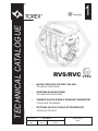
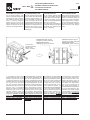
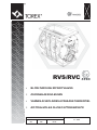
RVS/RVC
•
BLOW-THROUGH ROTARY VALVES
TECHNICAL CATALOGUE
•
DURCHBLASSCHLEUSEN
TECHNISCHER KATALOGUE
•
VANNES ALVEOLAIRES A PASSAGE TANGENTIEL
CATALOGUE TECHNIQUE
•
All rights reserved © WAMGROUP
TECHNICAL CATALOGUE
1
ROTOVALVOLE A FLUSSO ATTRAVERSATO
CATALOGO TECNICO
CATALOGUE No.
TO.310EX.T
CREATION DATE
ISSUE
CIRCULATION
DATE OF LATEST UPDATE
A2
100
03.07
12.04
03.07
- DESCRIPTION
- BESCHREIBUNG
RVS • RVC
- DESCRIPTION
1
- DESCRIZIONE
TO.310EX T. 01
TYPE
RVS - RVC
MASCHINENTYP
RVS - RVC
TYPE
RVS - RVC
DESCRIPTION
Blow-through rotary valves
BESCHREIBUNG
Durchblasschleusen
DÉSIGNATION
DESCRIZIONE
Vannes alveolaires a passage tan- Rotovalvola a flusso attraversato.
gentiel
USE
RVS - RVC series of rotary valves
are conceived and designed for
use in pneumatic conveyor systems, in accordance with the quality standards required by the market.
The two versions, RVS and RVC,
differ depending on the conveying motion of the material:
- The RVS version discharges
material inside a pneumatic
conveyor pipe
- The RVC version operates in the
same way as normal dropthrough rotary valves.
VERWENDUNGSZWECK
Die Durchblasschleusen der Baureihe RVS-RVC wurden für den
Einsatz in pneumatischen Förderanlagen entwickelt und entsprechen in vollem Umfang dem
marktüblichen Qualitätsstandard.
Die beiden Versionen RVS und
RVC unterscheiden sich durch die
Förderbewegung des Materials:
- Die RVS transferiert das Schüttgut in die Rohrleitung einer
pneumatischen Förderanlage.
- Die RVC funktionieren wie normale Dosierschleusen.
EMPLOI PRÉCONISÉ
Les vannes rotatives modèle RVS
- RVC sont indiquées pour être
utilisées dans les installations à
transport pneumatique, dans le
respect des standards de qualité
exigés par le marché.
Les deux versions, RVS et RVC se
différencient sur la base du mouvement de transport du produit:
- Les RVS déchargent le produit
à l’intérieur d’un tube de transport pneumatique.
- Le RVC fonctionnent comme
des vannes rotatives ordinaires.
TIPO
RVS - RVC
FUNZIONE D’USO
Le rotovalvole modello RVS RVC sono indicate per alimentazione e scarico controllato di prodotti in polvere o granulari da elementi di immagazzinamento.
Le due versioni, RVS e RVC si
differenziano in funzione del
moto di trasporto del materiale:
- Le RVS scaricano il materiale
all’interno di un tubo di trasporto pneumatico
- Le RVC funzionano come normali rotovalvole a caduta.
03.07
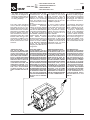
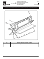
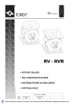
- GENERAL DIAGRAM
RVS • RVC
- GERÄTEAUFBAU
1
- SCHEMA GENERAL
TO.310EX T. 02
- SCHEMA GENERALE
TO
R
EX
TOREX
93550
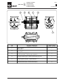
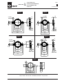
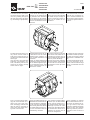
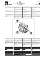
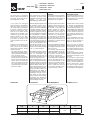
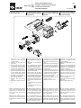
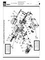
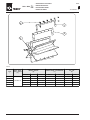
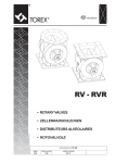
Item
Pos.
Description - Bezeichnung
Désignation - Descrizione
Quantity - Menge
Quantitè - Quantità
1
Casing - Gehäuse
Corps - Corpo
1
2
Rotor - Zellenrad
Rotor - Rotore
1
3
Drive plate - Antriebslagerschild
Couvercle motorsation - Coperchio porta motorizzazione
1
4
Motor driven or bare shaft - Antriebswellenzapfen
Arbre type motorisé ou type nu - Albero tipo motorizzato o tipo nudo
1
5
Cover plate opposite drive end - Abtriebsseitiger Lagerschild
Couvercle opposé motorisation - Coperchio lato folle
1
7
Conveying pipe connection - Förderleitungsanschluß
Connexion tube de transport - Imbocco tubo di trasporto
2
03.07
- TECHNICAL DATA
- TECHNISCHE DATEN
RVS • RVC
1
- DONNEES TECHNIQUES
TO.310EX T. 03
- DATI TECNICI
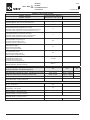
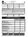
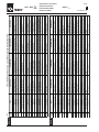
- Dimensions, footprint and rat- - Einbaumaße und Leistungsda- - Les dimensions, encombre- - Dimensioni, ingombri e potening are detailed in the next pag- ten sind auf den folgenden Sei- ments et puissances sont indi- ze applicate sono indicati nelle
schede seguenti.
es.
ten angegeben.
qués dans les fiches ci-dessous.
- Livello di rumorosità inferiore a
- Noise level: <85 dB(A).
- Geräuschpegel < 85 dB(A).
- Le niveau sonore est inférieur
85 dB(A).
à 85 dB(A).
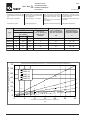
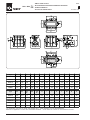
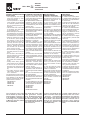
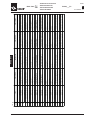
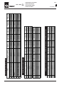
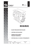
- Performance graph:
- Diagramme des performances: - Diagramma prestazioni:
- Leistungsdiagramm:
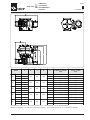
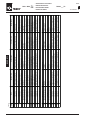
Throughput - Durchsatz - Débit - Portata
m3/h
Type
r.p.m. - min-1
tpm - giri/min
litres per rev.
Liter pro Umdrehung
litres par tour
litri al giro
Max. pressure differential
Max. Druckdifferenz
Diff. maxi de pression
Diff. max. di pressione
Operating temperature
Betriebstemperatur
Température d'emploi
Temperature d'utilizzo
bar
°C
10
20
30
RVS/C 05
3
6
9
5
0.7
-20 ÷ +60
RVS/C 10
5.4
10.8
16.2
9
0.7
-20 ÷ +60
RVS/C 15
8.4
16.8
25.2
14
0.7
-20 ÷ +60
RVS/C 20
12
24
36
20
0.7
-20 ÷ +60
RVS/C 35
22.8
45.6
68.4
38
0.7
-20 ÷ +60
Theoretical volumetric throughput (filling factor= 1) - Theoretische volumetrische Fördermenge (Füllfaktor = 1)
Débit volumétrique théorique (facteur de remplissage = 1) - Portata volumetrica teorica (fattore di riempimento= 1)
THROUGHPUT - DURCHSATZLEISTUNG - DEBIT - PORTATA
(m 3/h)
70
68,4
60
RVS/C 05
RVS/C 10
RVS/C 15
RVS/C 20
RVS/C 35
50
40
57
45,6
36
34,2
30
30
22,8
20
20
11,4
10
12
6
4,2
0
0
0
18
1,5
2,7
5
8,4
3
5,4
10
16,8
12,6
13,5
10,8
8,1
4,5
15
25,2
24
6
20
Rotor speed - Rotordrehzahl - Vitesse du rotor - Velocità rotore
(rpm)
7,5
25
16,2
9
30
03.07
- TECHNICAL DATA
RVS • RVC
- TECHNISCHE DATEN
1
- DONNEES TECHNIQUES
TO.310EX T. 04
- DATI TECNICI
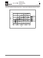
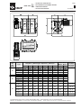
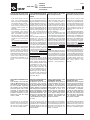
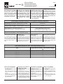
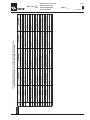
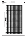
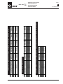
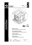
Losses due to pressure differential during operation - Verluste infolge Druckdifferenzen während des Betriebs
Pertes dûes au différentiel de pression durant l'exercice - Perdite dovute al differenziale di pressione in esercizio
120
100
RVS 05
Nm3/h
80
RVS 10
60
RVS 15
RVS 20
40
RVS 35
20
0
0,2
1
0,4
2
0,6
3
bar
0,8
4
03.07
- TECHNICAL DATA
- TECHNISCHE DATEN
RVS • RVC
1
- DONNEES TECHNIQUES
TO.310EX T. 05
- DATI TECNICI
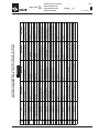
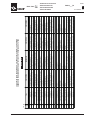
- The loading ratio in case of - Der Füllkoeffizient ändert sich - Dans le cas des poudres ou - Il coefficiente di riempimento nel
powders or similar materials bei staubförmigen oder ähnli- des matières similaires le coef- caso di polveri o materiali simili
varies accordino to the flowa- chen Gütern mit der Rieselfä- ficient de remplissage varie en varia in funzione della scorrebility of the material and rotor higkeit des Materials und der fonction de la fluidité du pro- volezza del prodotto e della verotation speed. Powder load- Rotationsgeschwindigkeit des duit et de la vitesse de rotation locità di rotazione del rotore.
ing coefficient (at optimum Rotors. Bei staubförmigem du rotor. Coefficient de remplis- Coefficiente di riempimento per
speed of 20 rpm) = 0.8.
Schüttgut und der optimalen sage pour les poudres (à vi- polveri (a velocità ottimale 20
Drehzahl von 20 min-1 beträgt tesse optimale 20 TR/MIN) = 0.8. RPM): 0.8.
der Füllgrad 80%.
r.p.m.
min-1
tpm
giri/min
Loading coefficient - Füllkoeffizient
Coefficient de remplissage - Coefficiente di riempimento
Material - Schüttgut - Matériau - Materiale
very free flowing - gut rieselfähig
très fluide - molto scorrevole
free flowing - rieselfähig
fluide - scorrevole
poorly flowing - schwach rieselfähig
peu fluide - poco scorrevole
< 10
0.9
0.85
0.8
10 ÷ 20
0.8
0.75
0.7
> 20
0.7
0.65
0.6
- Available speeds 10/20/30 - Standard-Drehzahl für Antrie- - Vitesses de base disponibles - Velocità di base disponibili 10/
RPM; speed variator 4-22 RPM. be mit konstanter Drehzahl = 10/20/30 TR/MIN; variateur 20/30 RPM; variatore con campo 4-22 RPM.
10/20/30 min-1; Standard-Re- avec plage de 4-22 TR/MIN.
gelbereich für mechanische
Regelantriebe = 4 bis 22 min-1.
- Wear is reduced at lower op- - Je niedriger die Drehzahl, de- - Limitation de l’usure aux vites- - Limitazione dell’usura alle veerating speeds. It is best to use sto geringer ist der Verschleiß. ses les plus basses: l’utilisa- locità più basse: è consigliabilarge cubic capacity at slow Besonders bei abrasiven Me- tion de grandes cylindrées à le impiegare grandi cilindrate a
speeds.
dien sollten daher großvolumi- basse vitesse est recomman- basse velocità.
ge und langsam drehende dée.
Schleusen verwendet werden.
The Table below gives certain
recommendations for the choice
of materials for construction of
the valves, depending on the
features of the product.
In der folgenden Tabelle stehen
einige Hinweise bezgl. der Wahl
der Werkstoffe der Zellen-radschleuse, die von den Eigenschaften des Produkts abhängen.
Le tableau ci-dessous fournit
quelques conseils de choix des
matériaux de construction de la
vanne, en fonction des caractéristiques du produit.
Nella tabella sottostante vengono dati alcuni consigli di scelta
materiali di costruzione della valvola, in funzione alle caratteristiche del prodotto.
Material for use with noncontaminating products:
Medien ohne besondere
Eigenschaften:
Application diverses de matières
Applicazioni varie di materiali
ne pouvant pas être contaminées: non contaminabili:
Body:
Cover:
Rotor:
Gehäuse: Grauguß
Endschilde: Grauguß
Zellenrad: Stahl
Corps:
Fonte grise
Couvercles: Fonte grise
Rotor:
Acier
Corpo:
Ghisa grigia
Coperchi: Ghisa grigia
Rotore:
Acciaio
Abrasive Medien:
Produits abrasifs:
Prodotti abrasivi:
grey cast iron
cast iron
steel
Abrasive products:
Body:
chromium or nickel plated
Gehäuse:
cast iron
Covers: chromium or nickel plated
Endschilde:
cast iron
Rotor: steel with Vulkolan scrapers Zellenrad:
Corps:
verchromter oder
vernickelter Grauguß
Couvercles:
verchromter oder
vernickelter Grauguß
Stahl mit SchleißleiRotor:
sten aus Vulkolan
Fonte grise chromée ou Corpo:
nickelée
Fonte grise chromée ou Coperchi:
nickelée
Acier avec bavettes en Rotore:
Vulkolan
Produits corrosifs:
Corrosive products:
Korrosive Medien:
Body:
nickel plated cast iron
Covers: nickel plated cast iron
Rotor: nickel plated cast iron
Gehäuse: vernickelter Grauguß Corps:
Fonte grise nickelée
Endschilde: vernickelter Grauguß Couvercles: Fonte grise nickelée
Fonte grise nickelée
Zellenrad: vernickelter Grauguß Rotor:
Ghisa grigia cromata o
nichelata
Ghisa grigia cromata o
nichelata
Acciaio con bavette in
Vulkolan
Prodotti corrosivi:
Corpo:
Ghisa grigia nichelata
Coperchi: Ghisa grigia nichelata
Rotore: Ghisa grigia nichelata
03.07
- FINISHING
- FINISH
RVS • RVC
1
- FINITION
TO.310EX T. 06
- FINITURA
*
3
3
Finishing
Finish
Finissage
Finitura
Paint
Anstrich
Peinture
Verniciatura
0
**
0
3
0
INTERNAL - INNEN - INTERIEUR - INTERNO
0
0
Paint
Anstrich
Peinture
Verniciatura
none
keiner
aucune
nessuna
Paint colour
Farbton Anstrich
Tonalité
Tonalità
none
keiner
aucune
nessuna
EXTERNAL - AUßEN - EXTERIEUR - ESTERNO
3
1)
2)
O
A
B
C
D
E
F
G
H
I
L
M
N
P
X
Y
Z
RAL 1013
RAL 1015
RAL 5010
RAL 5015
RAL 6011
RAL 7035
RAL 7032
RAL 7001
RAL 9001
RAL 9002
RAL 9010
Paint
Anstrich
Peinture
Verniciatura
1 primer+
1 paint coat
1x Grund+
1x Deck
1 antirouille+
1 peinture
1 mano
+ 1 mano
Paint colour
Farbton Anstrich
Tonalité
Tonalità
none
yellow Caterpillar*
pearl white
light ivory
gentian blue*
sky blue
reseda green
light grey*
pebble grey
silver grey
cream white
grey white
pure white
alluminium
ecological colour
non ecological colour
to be specified
Keiner
Caterpillar gelb*
Perlweiss
Hellelfenbein
Enzianblau*
Himmelblau
Resedagrün
Lichtgrau*
Kieselgrau
Silbergrau
Cremeweiß
Grauweiß
Reinweiß
Aluminium
Ökofarben
Nicht-Ökofarben
Zu spezifizieren
aucune
jaune Caterpillar*
blanc perle
ivoire clair
bleu gentiane*
bleu ciel
vert réséda
gris lumière*
gris gravier
gris argent
blanc crème
blanc gris
blanc pur
Aluminium
Tonalité écologiques
Tonalités non écologiques
à préciser
nessuna
giallo Caterpillar*
bianco perla
avorio chiaro
blu genziana*
blu cielo
verde reseda
grigio luce*
grigio ghiaia
grigio argento
bianco crema
bianco grigio
bianco puro
Alluminio
Tonalità ecologiche
Tonalità non ecologiche
su specifica
* Recommended colours
* Empfohlene Farben
1) See Table X page T.10
1) Siehe Tabelle X, Seite T.10
2) See Table Y page T.10
2) Siehe Tabelle Y, Seite T.10
Specify colours in tables X and Farbtöne für Tabellen X und Y
Y in the order.
in der Bestelung angeben.
The antirust is a red-brown colour.
The paint is not applied on the
drive unit (motor, reduction unit,
speed changer, pretorque). The
paint must however be less than
0.2 mm thick.
Farbton Grundanstrich = rotbraun.
Die Motorgruppe (Motor, Untersetzungsgetriebe, Regler, Vorgelege) wird nicht lackiert. Die Lachstärke beträgt auf jeden Fall
immer weniger als 0.2 mm.
* Tonalités conseillées
* Tonalità consigliate
1) Voir tab. X, page T.10
2) Voir tab. Y, page T.10
Spécifier Tonalités pour tab.
X et Y dans la commande.
1) Vedi Tab. X pag. T.10
2) Vedi Tab. Y pag. T.10
Le tonalità delle tabelle X e Y devono essere specificate nell’ordine.
Tonalité antirouille = rouge-marron.
La peinture n’est pas appliquée
sur le groupe motorisation (moteur, réducteur, variateur, précouple).
L’épaisseur de la peinture est
toujours inférieure à 0,2 mm.
Tonalità antiruggine = rosso-marrone.
La verniciatura non viene applicata sul gruppo motorizzazione
(motore, riduttore , variatore,
precoppia).Lo spessore della
vernice è sempre comunque inferiore a 0.2 mm.
RVS • RVC
- COLOURS
03.07
- FARBTÖNE
1
- TONALITES
TO.310EX T. 07
- TONALITÀ
X
- “ECOLOGICAL” RAL COLOURS THAT DO NOT CONTAIN LEAD OR CHROME
- “ÖKOLOGISCHE” RAL-TÖNE OHNE BLEI- UND CHROMANTEILE
- TONALITES RAL “ECOLOGIQUES” SANS CHROME ET PLOMB
- TONALITÀ RAL “ECOLOGICHE” SENZA CROMO E PIOMBO
1000
1001
1002
1011
1014
1019
3005
3007
3009
3027
4001
4004
4005
4006
4007
4008
5000
5001
6000
6003
5002
5003
5004
5005
5507
5008
5009
5011
5012
5013
5014
5017
6004
6006
6012
6013
6015
6016
6019
6020
6021
6022
6025
6026
6027
6028
6033
6034
7000
7024
7002
7003
7004
7005
7006
7007
7008
7009
7010
7011
7012
7013
7015
7016
7021
7022
7023
7025
7026
7030
7031
7033
7034
7036
7037
7038
7039
7040
7042
7043
7044
8000
8001
8002
8004
8011
8015
8016
8017
8019
8022
8024
8025
8028
9003
9004
9005
9011
9016
9017
9018
Y
- “NON ECOLOGICAL” RAL COLOURS CONTAINING LEAD OR CHROME
- NICHT “ÖKOLOGISCHE” RAL-TÖNE MIT BLEI- UND CHROMANTEILEN
- TONALITES RAL “NON ECOLOGIQUES” AVEC CHROME ET PLOMB
- TONALITÀ RAL “NON ECOLOGICHE” CONTENENTI CROMO - PIOMBO
RAL 1006
Maize yellow
Maisgelb
Jaune mais
Giallo mais
RAL 1007
Chrome yellow
Chromgelb
Jaune chrome
Giallo cromo
RAL 1018
Zinc yellow
Zinkgelb
Jaune zinc
Giallo zinco
RAL 2008
Light red orange
Hellrotorange
Rouge orange clair
Arancio rosso chiaro
RAL 6017
May green
Maigrün
Vert mai
Verde maggio
RAL 6018
Yellow green
Gelbgrün
Vert jaune
Verde giallo
03.07
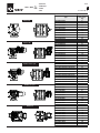
- ORDER CODES
- BESTELLCODES
RVS • RVC
1
- CODES DE SELECTION
TO.310EX T. 08
- CODICI DI SCELTA
RVS
20
10
1
A
0
A
A
X
ROTOR
ZELLENRAD
ROTOR
ROTORE
C
Teflon coated
Teflon-beschichtet
Téflonné
Teflonato
H
Stainless Steel 304
Edelstahl 1.4301
Inox 304
AISI 304
B
Chromé
Cromato
BODY TREATMENT
BEHANDLUNG GEHÄUSE
TRAITEMENT CORPS
TRATTAMENTO CORPO
Nickel coated
Vernickelt
0
C Nickelé
Nichelato
A
SEALS - WELLENABDICHTUNGEN
JOINTS - TENUTE
C
TIP SCRAPERS - SCHLEISSLEISTEN
BAVETTES - BAVETTE
A
Vulkolan
Vulkolan
Vulkolan
Vulkolan
High temperature
Hohe Temperatur
Haute température
Alta temperatura
Bare shaft
B
Viton ®
®
Viton
®
Viton
Viton ®
Arbre nu
Albero nudo
Variateur
Variatore meccanico
RPM
-1
10 min
TR/MIN
giri al minuto
1S
DRIVE UNIT
ANTRIEB
MOTORISATION
MOTORIZZAZIONE
-1
Teflon
Teflon
Teflon
Teflon
304 Stainless Steel
Edelstahl 1.4301
Inox AISI 304
Inox AISI 304
0
Without tip scrapers
Ohne Schleißleisten
Sans bavettes
Senza bavette
5
316 Stainless Steel
Edelstahl 1.4401
Inox AISI 316
Inox AISI 316
Speed variator without motor
Regelantrieb ohne Motor
Variateur sans moteur
Variatore meccanico senza motore
-1
30 min
TR/MIN
giri al minuto
giri al minuto
10 RPM with motor Servo ventilated
10 min-1mit E-Motor Zwangsbelüftet
10 TR/MIN avec moteur Servo-ventilé
10 giri al minuto con motore Servoventilato
20 RPM with motor Servo ventilated
30 RPM with motor Servo ventilated
2S 20 min-1mit E-Motor Zwangsbelüftet
3S 30 min-1mit E-Motor Zwangsbelüftet
20 TR/MIN avec moteur Servo-ventilé
20 giri al minuto con motore Servoventilato
Without motor with gear reducer 10 RPM
Motor mit Getriebe 10 RPM
SP Ohne
Sans moteur avec réducteur 10 RPM
SM
Senza motore con riduttore 10 RPM
Chain transmission 10 RPM
VS
D
B
RPM
RPM
20 min
TR/MIN
2
Fonte
Ghisa
Speed variator
Standard
Standard
Standard
Standard
Purged seals
Sperrspülungen
Etanchéités fluxées
Tenute flussate
Standard
High temperature resistant purged seals
Sperrspülungen für hohe Temperatur
0 Standard
Standard
Etanchéités fluxées Haute température
Standard
Tenute flussate Alta temperatura
1 Grauguß
AN Freie Welle ohne Antrieb V M Regelantrieb
0
Standard
Standard
Standard
Standard
Cast iron
MATERIAL BODY - GEHÄUSE STOFFE
MATERIAUX CORPS - MATERIALE CORPO
M
Stainless Steel 316
Edelstahl 1.4401
Inox 316
AISI 316
Teflon coated
Teflon-beschichtet
Teflonné
Teflonato
Chromium plated
A Verchromt
Nickel plated
Vernickelt
Nickelé
Nichelato
D
without motor
ohne E-Motor
sans moteur
senza motore
30 TR/MIN avec moteur Servo-ventilé
30 giri al minuto con motore Servoventilato
Chain transmission without gear reducer
without gear red.
Getriebe
SR ohne
sans réducteur
Chain transmission 20 RPM
TS Kettentrieb ohne Getriebemotor
senza riduttore
Transmission à chaîne sans motoréducteur
Trasmissione a catena senza motoriduttore
Chain transmission 30 RPM
10RPM
20RPM
30RPM
1C Kettentrieb
2C Kettentrieb
3C Kettentrieb
Entraînement par chaîne 10 RPM
Entraînement par chaîne 20 RPM
Entraînement par chaîne 30 RPM
Trasmissione a catena 10RPM
1T
10 RPM with motor with Thermistors
10 min-1mit E-Motor mit Thermistoren
10 TR/MIN avec moteur avec Thermistances
10 giri al minuto con motore con Termistori
SIZE - GRÖßE
TAILLE - GRANDEZZA
Blow-through rotary valve
RVS Durchblasschleuse
RVS - RVC
Trasmissione a catena 20RPM
Vanne alvéolaire à passage tangentiel
Rotovalvola a flusso attraversato
Fall-through rotary valve
RVC Freifallschleuse
Vanne alvéolaire à chute
Rotovalvola a caduta
2T
Trasmissione a catena 30RPM
20 RPM with motor with Thermistors
20 min-1mit E-Motor mit Thermistoren
20 TR/MIN avec moteur avec Thermistances
20 giri al minuto con motore con Termistori
3T
30 RPM with motor with Thermistors
30 min-1mit E-Motor mit Thermistoren
30 TR/MIN avec moteur avec Thermistances
30 giri al minuto con motore con Termistori
05 5 Litres for revolution - Liter pro Umdrehung - litres pour tour - litri per giro
10 10 Litres for revolution - Liter pro Umdrehung - litres pour tour - litri per giro
15 15 Litres for revolution - Liter pro Umdrehung - litres pour tour - litri per giro
20 20 Litres for revolution - Liter pro Umdrehung - litres pour tour - litri per giro
35 35 Litres for revolution - Liter pro Umdrehung - litres pour tour - litri per giro
03.07
-TOP AND BOTTOM FLANGE
-OBERER UND UNTERER FLANSCH
RVS • RVC
1
-BRIDE SUPERIEURE ET INFERIEURE
TO.310EX T. 09
-FLANGIATURE SUPERIORE E INFERIORE
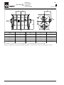
B1
B2
C1
E2
E3
E3
n°
220 585 332 300 540
180
C2
D1
F2
F3
F3
N°
G1
G1
N°
G2
N°
3
300 540
180
3
M 12
8
14
8
195
2
250 390
195
2
M 12
6
13
6
194 310
155
2
194 310
155
2
M 10
6
12
6
172 270
135
2
172 270
135
2
M8
6
10
6
184 164 210
105
2
164 210
105
2
M8
6
9
6
Type
A1
A2
RVS/C 35
470
240 585 352 480
RVS/C 20
337
196 428
RVS/C 15
276
148 342 222 276
158 342 222
RVS/C 10
238
135 298 200 235
135 298 200
RVS/C 05
170 122 234
278 337 200 428
184 166
121 234
D2
E1
278 250 390
F1
03.07
- PIPE CONNECTION
- ROHRLEITUNGSVERBINDUNG
RVS • RVC
1
- RACCORDEMENT TUBE
TO.310EX T. 10
- IMBOCCHI
RVS 35
RVS 15
2 x Ø14
2 x Ø10
10
24
30
Ø140.5
16
Ø118
15
Ø127
30
185
Ø74
10
Ø81
20
116
220
136
RVS 20
RVS 10
2 x Ø13
2 x Ø9
9
28
20
Ø115
15
Ø96
14
Ø103
30
145
Ø64
9
Ø71
18
90
173
108
RVS 05
18
Ø70
2xØ9
Ø54
Ø61
Ø92
8
16
Ø108
Only for RVS - Nur für RVS - Seulement pour RVS - Solo per RVS
03.07
- SIMPLE STEM VALVES
- ZELLENDRADSCHLEUSEN MIT FREIEM WELLENZAPFEN
RVS • RVC
1
- VANNES A ARBRE NU
TO.310EX T. 11
- VALVOLE AD ALBERO NUDO
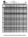
Type
A1
A2
B1
B2
C1
C2
D1
D2
E1
E2
E3
F1
F2
RVS 35
470
240
585
352
480
220
585
332
300
540
180
300
540
RVS 20
337
196
428
278
337
200
428
278
250
390
195
250
390
RVS 15
276
148
342
222
276
158
342
222
194
310
155
194
310
RVS 10
238
135
298
200
235
135
298
200
172
270
135
172
270
RVS05
170
122
234
184
166
122
234
184
164
810
105
161
210
Type
F3
G1
G1
N°
G2
G2
N°
H
I
J
K
L
M
N
P
RVS 35
180
M 12
8
14
8
530
118
105
185
430
732
72
40
RVS 20
195
M 12
6
13
6
447
96
88
160
362
592
70
32
RVS 15
155
M 10
6
12
6
399
74
69
153
323
504
76
32
RVS 10
135
M8
6
10
6
339
64
54
129
280
455
58
28
RVS05
105
M8
6
10
6
335
54
55
130
270
400
72
28
The dimensions given refer to valves with standard drive. - Werte beziehen sich auf Standardantriebe.
Mesures se rapportant à la vanne avec motorisation standard. - Quote riferite alla valvola con motorizzazione standard.
03.07
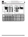
- VALVES WITH GEAR MOTOR
RVS • RVC
- ZELLENDRADSCHLEUSEN MIT ANTRIEB
1
- VANNES MOTORISÉES
TO.310EX T. 12
- VALVOLE MOTORIZZATE
TOREX
r.p.m.
min-1
tpm
giri/min
30
20
10
Type
Motor - Motor
Moteur - Motore
Dimensions - Abmessungen - Dimensions - Dimensioni
Q1
Q2
Q3
R1
R2
R3
H
kW
Giri
RVS/C 35
890
558
332
740
217
523
530
2.2
1400
RVS/C 20
705
444
261
608
181
426
447
1.5
1400
RVS/C 15
605
390
215
588
162
426
399
1.1
1400
RVS/C 10
572
372
200
560
140
420
339
0.75
1400
RVS/C 05
505
342
163
550
130
420
335
0,75
1400
RVS/C 35
890
558
332
740
217
523
530
1.5
900
RVS/C 20
705
444
261
608
181
426
447
1.1
900
RVS/C 15
605
390
215
588
162
426
399
0.75
900
RVS/C 10
572
372
200
560
140
420
339
0.55
900
RVS/C 05
505
342
163
550
130
420
335
0,55
900
RVS/C 35
890
558
332
740
217
523
530
*1.1
900
RVS/C 20
658
397
261
591
181
410
447
*0.75
1400
RVS/C 15
585
370
215
572
162
410
399
0.55
1400
RVS/C 10
542
342
200
527
140
387
339
*0.37
1400
RVS/C 05
475
342
163
517
130
387
335
0,37
1400
Pretorque
Vorgelege
Précouple
Precoppia
no - nein
no - no
yes - ja
oui - si
yes - ja
oui - si
yes - ja
oui - si
The dimensions given refer to valves with standard drive. - Werte beziehen sich auf Standardantriebe.
Mesures se rapportant à la vanne avec motorisation standard. - Quote riferite alla valvola con motorizzazione standard.
03.07
- VALVES WITH VARIABLE SPEED MOTOR
- ZELLENDRADSCHLEUSEN MIT MECHANISCHEM REGELANTRIEB
RVS • RVC
- VANNES AVEC MOTOVARIATEUR MECANIQUE
- VALVOLE MOTORIZZATE CON MOTOVARIATORE DI GIRI
Motor - Motor
Moteur - Motore
Dimensions - Abmessungen
Dimensions - Dimensioni
Type
1
TO.310EX T. 13
Variator - Regelgetriebe
Variateur - Variatore
Rotor - Rotor
Rotor - Rotore
Q1
Q2
Q3
R1
R2
R3
H
kW
rpm - min -1
tpm - giri
rpm - min-1
tpm - giri
rpm - min-1
tpm - giri
RVS/C 35
930
596
332
870
217
653
530
1.5
1400
190 - 1000
4 - 20
RVS/C 20
788
527
261
743
181
562
447
0.75
1400
190 - 1000
4 - 20
RVS/C 15
639
424
215
724
162
562
399
0.75
1400
190 - 1000
4 - 20
RVS/C 10
474
380
200
615
140
475
339
0.37
1400
190 - 1000
4 - 20
RVS/C05
407
244
163
605
130
475
335
0.37
1400
190-1000
4 - 20
The dimensions given refer to valves with standard drive. - Werte beziehen sich auf Standardantriebe.
Mesures se rapportant à la vanne avec motorisation standard. - Quote riferite alla valvola con motorizzazione standard.
03.07
- DIMENSIONS
- PLATZBEDARF
RVS • RVC
1
- ENCOMBREMENTS
TO.310EX T. 14
- INGOMBRI
RVS/C
05
10
15
20
35
A
B
C
D
E
Power - Leistung
Puissance - Potenza
(kW)
Torque - Drehmoment
Couple - Coppia
(Nm)
345
0.37
300
10rpm
630
20rpm
630
345
0.55
232
30rpm
630
345
0.55
149
10 rpm
630
310
0.37
300
20 rpm
630
310
0.55
232
30 rpm
630
310
0.55
149
10 rpm
700
360
0.55
472
525
545
627
492
492
390
20 rpm
650
310
0.75
328
30 rpm
650
310
1.1
308
10 rpm
700
340
0.55
472
672
620
380
20 rpm
650
290
0.75
328
30 rpm
650
290
1.1
308
10 rpm
700
240
1.1
929
20 rpm
750
30 rpm
750
796
620
430
810
460
580
190
1.5
633
190
2.2
630
The dimensions given refer to valves with standard drive. - Werte beziehen sich auf Standardantriebe.
Mesures se rapportant à la vanne avec motorisation standard. - Quote riferite alla valvola con motorizzazione standard.
03.07
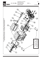
- AIR OUTLET
- LUFTAUSLASS
RVS • RVC
1
- SORTIE D’AIR
TO.310EX T. 15
- SCARICHI D’ARIA
Type
A
B
C
D
RVS/C 05
136
106
213
3/4" GAS
RVS/C 10
145
63
213
3/4" GAS
RVS/C 15
166
72
253
3/4" GAS
RVS/C 20
181
100
279
3/4" GAS
RVS/C 35
217
160
332
3/4" GAS
The dimensions given refer to valves with standard drive. - Werte beziehen sich auf Standardantriebe.
Mesures se rapportant à la vanne avec motorisation standard. - Quote riferite alla valvola con motorizzazione standard.
03.07
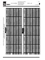
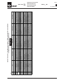
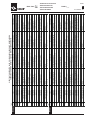
- DRIVE UNIT DATA
RVS • RVC
- ANTRIEBSDATEN
1
- CARACTÉRISTIQUES MOTORISATION
TO.310EX T. 16
- DATI MOTORIZZAZIONE
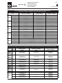
Locked rotor torque/
Power
Type
RVS/C
10
RVS/C
15
RVS/C
20
RVS/C
35
Current
Voltage
Efficiency
Power factor
Rated Torque
Locked rotor current/
rated courrent
No of Drehzahl Strom Spannung Wirksamkeit
Nenndrehmoment
Leistungsf.
Drehmoment blockiert Rotor/ Strom blockierter Rotor/
Puissance poles Vitesse Courant Tension
Efficacité
Couple nominal
Baugröße
Facteur de
Nenndrehmomen
Nenndrehmomen
Potenza N.pole Velocità Corrente Voltaggio Efficienza
Coppia nominale
Taille
puissance
Couple rotor bloqué/
Courant rotor bloqué/
N.pôles
Taglia
Fattore di
Couple nominal
Couple nominal
N.poli
potenza
Coppia rotore bloccato/
Corrente a rotore bloccato/
(kW)
(tr/min)
(A)
(V)
(% )
(Nm)
coppia nominale
coppia nominale
Size
RVS/C
05
Speed
rated torque
Leistung
10 rpm
71
0.37
4
1400
1,1
380
67.0
0.75
2.52
2.1
5,2
20 rpm
80
0.5
6
930
1,8
380
65.0
0.72
5.13
1.9
4.7
30 rpm
80
0.5
4
1410
1.6
380
71.0
0.75
3.39
2.4
5.2
VM
71
0.37
4
1400
1.1
380
67.0
0.75
2.52
1.9
5.2
TC
10 rpm
71
0.37
4
1400
1.1
380
67.0
0.75
2.52
1.9
5.2
TC
20 rpm
80
0.55
6
900
1.8
380
65.0
0.72
5.84
1.9
4.7
TC
30 rpm
80
0.55
4
1400
1.6
380
71.0
0.75
3.75
2.4
5.2
10 rpm
71
0.37
4
1400
1,1
380
67.0
0.75
2.52
2.1
5,2
20 rpm
80
0.5
6
930
1,8
380
65.0
0.72
5.13
1.9
4.7
30 rpm
80
0.5
4
1410
1.6
380
71.0
0.75
3.39
2.4
5.2
VM
71
0.37
4
1400
1.1
380
67.0
0.75
2.52
1.9
5.2
TC
10 rpm
71
0.37
4
1400
1.1
380
67.0
0.75
2.52
1.9
5.2
TC
20 rpm
80
0.55
6
900
1.8
380
65.0
0.72
5.84
1.9
4.7
TC
30 rpm
80
0.55
4
1400
1.6
380
71.0
0.75
3.75
2.4
5.2
10 rpm
80
0.55
4
1400
1.6
380
71.0
0.75
3.75
2.4
5.2
20 rpm
90
0.75
6
940
2.3
380
69.0
0.72
7.62
2.0
5.5
30 rpm
90
1.1
4
1410
2.9
380
75.0
0.77
7.45
2.3
6.0
VM
80
0.75
4
1410
2.0
380
73.0
0.77
5.08
2.4
6.0
TC
10 rpm
80
0.55
4
1400
1.6
380
71.0
0.75
3.75
2.4
5.2
TC
20 rpm
90
0.75
6
900
2.3
380
69.0
0.72
7.62
2.0
5.5
TC
30 rpm
90
1.1
4
1410
2.9
380
75.0
0.77
7.45
2.3
6.0
10 rpm
80
0.75
4
1410
2.0
380
73.0
0.77
5.08
2.4
6.0
20 rpm
90
1.1
6
900
3.2
380
72.0
0.73
11.67
2.0
5.5
30 rpm
90
1.5
4
1410
3.7
380
78.0
0.79
10.16
2.3
6.0
VM
80
0.75
4
1410
2.0
380
73.0
0.77
5.08
2.4
6.0
TC
10 rpm
80
0.5
4
1410
1.6
380
71.0
0.75
3.39
2.4
5.2
TC
20 rpm
90
1.1
6
900
3.2
380
72.0
0.73
11.67
2.0
5.5
TC
30 rpm
90
1.1
4
1410
2.9
380
75.0
0.77
7.45
2.3
6.0
10 rpm
90
1.1
4
1410
2.9
380
75.0
0.77
7.45
2.3
6.0
20 rpm
100
1.5
6
900
3.9
380
76.0
0.76
15.92
2.0
5.5
30 rpm
100
2.2
4
1410
5.2
380
80.0
0.81
14.90
2.3
7.0
VM
100
1.5
4
1410
3.7
380
78.0
0.79
10.16
2.3
6.0
TC
10 rpm
90
1.1
4
1410
2.9
380
75.0
0.77
7.45
2.3
6.0
TC
20 rpm
100
1.5
6
900
3.9
380
76.0
0.76
15.92
2.0
5.5
TC
30 rpm
100
2.2
4
1410
5.2
380
80.0
0.81
14.90
2.3
7.0
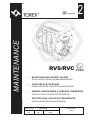
MAINTENANCE
2
RVS/RVC
•
BLOW-THROUGH ROTARY VALVES
INSTALLATION, OPERATION AND MAINTENANCE
•
DURCHBLASSCHLEUSEN
EINBAU, BETRIEBS- UND WARTUNGSANLEITUNG
•
VANNES ALVEOLAIRES A PASSAGE TANGENTIEL
INSTALLATION, UTILISATION ET ENTRETIEN
All rights reserved © WAMGROUP
•
ROTOVALVOLE A FLUSSO ATTRAVERSATO
INSTALLAZIONE USO E MANUTENZIONE
CATALOGUE No.
TO.310EX.M
CREATION DATE
ISSUE
CIRCULATION
DATE OF LATEST UPDATE
A2
100
03.07
12.04
03.07
- DESCRIPTION
- BESCHREIBUNG
RVS • RVC
- DESCRIPTION
2
- DESCRIZIONE
TO.310EX M. 01
TYPE
RVS (Blow-through rotary valve)
RVC(Fall-through rotary valve)
DESCRIPTION
Blow-through rotary valves
MASCHINENTYP
RVS (Durchblasschleuse)
RVC (Freifallschleuse)
BESCHREIBUNG
Durchblasschleusen
USE
RVS - RVC series of rotary valves
are conceived and designed for
use in pneumatic conveyor systems, in accordance with the quality standards required by the market.
The two versions, RVS and RVC,
differ depending on the conveying motion of the material:
- The RVS version discharges
material inside a pneumatic
conveyor pipe
- The RVC version operates in the
same way as normal dropthrough rotary valves.
In both versions, the upper outlet
flange must be firmly fixed to the
silo or to the loading hopper, while
particular attention must be paid
to the connection of the lower
flange in the RVC version, and to
the inlet of the conveyor pipe in
the RVS version.
Please note that the connection
bores on the upper flange are
threaded, while those on the lower flange are not.
VERWENDUNGSZWECK
Die Durchblasschleusen der Baureihe RVS-RVC wurden für den
Einsatz in pneumatischen Förderanlagen entwickelt und entsprechen in vollem Umfang dem
marktüblichen Qualitätsstandard.
Die beiden Versionen RVS und
RVC unterscheiden sich durch die
Förderbewegung des Materials:
- Die RVS transferiert das Schüttgut in die Rohrleitung einer
pneumatischen Förderanlage.
- Die RVC funktionieren wie normale Dosierschleusen.
In beiden Fällen muß der obere
Einlaufflansch fest mit dem Silo
oder dem Aufgabetrichter verbunden werden. Während bei der
Version RVC besonders auf die
Befestigung des unteren Flansches zu achten ist, gilt dies im
Falle der Version RVS für die Verbindung mit der Rohrleitung des
pneumatischen Fördersystems.
Bei den Bohrungen im oberen
Flansch handelt es sich um Gewindebohrungen, bei denen im
unetern Flansch um Durchgangsbohrungen.
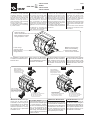
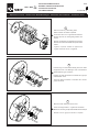
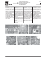
The rotors of the RVS and RVC in
all the version have inclined
blades: this allows the gradual
transport of material.
Die Zellenräder der Modelle RVS
und RVC haben in allen Versionen schräg stehende Zellenwände. Dies bewirkt eine kontinuierliche Produktförderung.
For the versions with bevelled
blades, the edge which cuts the
flow of material entering the Rotary Valve is always unbevelled:
a reversal of the direction of rotation would lead to the compression of the material between the
blades and the body.
In the RVS version the inclination of the blades defines the direction of the conveyance movement, as the first material discharged must also be the first to
be expelled: care must be taken
not to push freshly discharged
material under the material still
in the process of being discharged.
Für die Versionen mit abgeschrägten Flügeln ist die Kante, die den
Strom des einlaufenden Materials in der Zellenradschleuse
durchtrennt, immer die nicht gefaste Kante: Eine Umkehr der
Drehrichtung würde dazu führen,
daß sich das Material zwischen
Zellenrad und Gehäuse verpreßt.
Bei der Version RVS ist die Neigung der Flügel ausschlaggebend
für die Förderrichtung, weil das
zuerst aufgegebene Material auch
jenes ist, das zuerst ablaufen muß.
Es ist zu vermeiden, Material, das
bereits ausgelaufen ist, gegen
jenes drücken, welches gerade abgeladen wird.
TYPE
RVS (Vanne alvéolaire à passage tangentiel)
RVC (Vanne alvéolaire à chute)
DÉSIGNATION
Vannes alveolaires a passage tangentiel
EMPLOI PRÉCONISÉ
Les vannes rotatives modèle RVS
- RVC sont indiquées pour être
utilisées dans les installations à
transport pneumatique, dans le
respect des standards de qualité
exigés par le marché.
Les deux versions, RVS et RVC se
différencient sur la base du mouvement de transport du produit:
- Les RVS déchargent le produit
à l’intérieur d’un tube de transport pneumatique.
- Le RVC fonctionnent comme
des vannes rotatives ordinaires.
Dans les deux cas, la bride supérieure de chargement doit être solidement reliée au silo ou à la
trémie de chargement, tandis
qu’il faut faire tout particulièrement attention à la liaison de la
bride inférieure pour les RVC, et
à l’entrée du tube de transport
pour les RVS.
On remarquera que les trous de
fixation de la bride supérieure
sont filetés, tandis que ceux de la
bride inférieure ne le sont pas.
TIPO
RVS (rotovalvole a caduta)
RVC (Rotovalvola a flusso attraversato )
DESCRIZIONE
Rotovalvola a flusso attraversato.
FUNZIONE D’USO
Le rotovalvole modello RVS RVC sono indicate per alimentazione e scarico controllato di prodotti in polvere o granulari da elementi di immagazzinamento.
Le due versioni, RVS e RVC si
differenziano in funzione del
moto di trasporto del materiale:
- Le RVS scaricano il materiale
all’interno di un tubo di trasporto pneumatico
- Le RVC funzionano come normali rotovalvole a caduta.
In entrambi i casi, la flangia superiore di carico deve essere saldamente connessa al silo o alla
tramoggia di carico, mentre occorre prestare particolare cura alla
connessione della flangia inferiore per le RVC, e dell’imbocco del
tubo di trasporto per le RVS.
Da notare che i fori di fissaggio
presenti sulla flangia superiore
sono filettati, mentre quelli presenti sulla flangia inferiore no.
Les rotors de la RVS et RVC sont,
dans toutes les versions, à pales
inclinées. Ceci permet d’obtenir
un transport graduel du produit.
I rotori delle RVS e RVC sono, in
tutte le versioni, a pale inclinate:
questo permette un trasporto graduale del prodotto.
Pour les versions à pales chanfreinées, l’arête qui doit couper
le flux de produit entrant dans la
vanne rotative est toujours celle
qui est chanfreinée. Une inversion du sens de rotation provoquerait l’écrasement du produit
entre les pales et le corps.
Per le versioni a pale smussate,
lo spigolo che deve tagliare il flusso del materiale entrante nella
rotovalvola è sempre quello non
smussato: una inversione nel senso di rotazione comporterebbe lo
schiacciamento del materiale fra
le pale ed il corpo.
Dans les versions RVS l’inclinaison des pales impose le sens du
mouvement du transport, car le
produit déchargé en premier doit
aussi être le premier à sortir. Il
faut éviter de pousser le produit
qui vient d’être déchargé sous
celui qui est en cours de déchargement.
Nelle versione RVS l’inclinazione delle pale impone il senso del
moto del trasporto, in quanto il
primo materiale scaricato deve essere anche il primo ad uscire: si
deve evitare di spingere il materiale appena scaricato sotto quello che si stà scaricando.
03.07
- DESCRIPTION
RVS • RVC
- BESCHREIBUNG
- DESCRIPTION
- DESCRIZIONE
2
TO.310EX M. 02
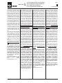
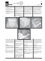
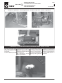
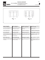
In the RVS version, the connection of the conveyor pipe is carried out by welding the pipe to
the rotary valve inlet or by clamping and sealing it appropriately.
Für die Version RVS erfolgt der
Anschluß an die Förderrohrleitung entweder durch Anschweißen des Rohrs an das Auslaufrohr der Zellenradschleuse oder
Klemmen und Abdichten des Anschlusses:
Dans la version RVS, le raccordement du tuyau tube transport
est réalisé soit par soudage du
tube sur l’entrée de la vanne rotative, soit en scellant ce raccordement:
Per la versione RVS, la connessione del tubo di trasporto avviene o mediante saldatura del
tubo all’imbocco della rotovalvola o comunque sigillando tale connessione:
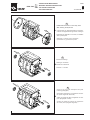
The RVS and RVC series of rotary valves include outlets to
expel the air which fills the vanes when the material has been
discharged.
Once the rotary valve has been
positioned, it is possible to proceed, if necessary, with the connection of the outlets, normally
closed with two plugs:
Die Zellenradschleusen der Serie RVS RVC sind mit Entlüftungsbohrungen versehen, um
die im Produkt enthaltene Luft
abzulassen.
Soabld die Zellenradschleuse
eingebaut ist, können je nach Bedarf die Entlüftungsbohrungen,
die normalerweise durch zwei
Stopfen verschlossen sind, angeschlossen werden.
Les vannes rotatives de la série
RVS et RVC sont dotées de refoulement pour chasser l’air qui
rempli les alvéoles en prenant la
place du produit déchargé.
Une fois que la vanne rotative a
été mise en place, il est possible
de raccorder les refoulements,
normalement fermés par deux
bouchons.
Le rotovalvole serie RVS RVC
sono dotate di scarichi per espellere l’aria che riempie gli alveoli
sostituendosi al materiale scaricato.
Una volta posizionata la rotovalvola si può procedere, se necessario, alla connessione degli
scarichi, normalmente chiusi da
due tappi:
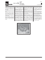
This is of further help in identifying the correct direction of rotation of the rotor: each vane,
after discharging material and
filling up with air, must pass in
front of the vents before arriving back under the inlet.
Dies ist eine weitere Hilfe für die
Identifikation der korrekten Drehrichtung des Rotors. Jede Zelle,
die sich nach der Schüttgutabgabe mit Luft gefüllt hat, läuft an
den Entlüftungsbohrungen vorbei, bevor sie wieder unter der
Einlauföffnung erscheint.
Ceci constitue une aide supplémentaire pour la détermination
du bon sens de rotation du rotor. Chaque alvéole, après avoir
déchargé le produit et s’être
remplie d’air, doit passer devant
les refoulements avant de se
présenter de nouveau sous la
bouche de chargement.
Questo costituisce un ulteriore
aiuto all’individuazione del corretto senso di rotazione del rotore: ogni alveolo, dopo aver
scaricato il materiale ed essersi
riempito di aria, deve passare
davanti agli scarichi prima di ripresentarsi sotto la bocca di
carico.
RVS • RVC
- MANUFACTURING DATA
03.07
- KONSTRUKTIONSDATEN
2
- DONNÉES CONSTRUCTIVES
TO.310EX M. 03
- DATI COSTRUZIONE
IDENTIFICATION
OF THE MACHINE
IDENTIFIKATION
DER MASCHINE
Refer to the code on the rating Zur korrekten identifikation auf
plate affixed to the machine, to den Bestellcode in der Auftragsidentify equipment.
bestätigung, in der Rechnung
und auf der Verpackung Bezug nehmen.
IDENTIFICATION
DE LA MACHINE
IDENTIFICAZIONE
DELLA MACCHINA
Pour identifier correctement la
machine, vous devez vous référer au code qui se trouve sur la
confirmation de commande, sur
la facture et sur la plaque qui se
trouve sur l’emballage.
Per una corretta identificazione
della macchina, bisogna fare
riferimento al codice che si trova sulla targhetta posta sulla stessa.
RVS101010000X
Serial No. 000-10-06-00
Year
Type
0123
Op.
2006
N.C.
II 1D/3D c T135°C
Cert.No.EX 5 06 12 61456 002
R
Max.Rotor speed: 30 rpm
TOREX SpA
R
R
WAMGROUP
Tamb. -10°C / +40°C
1)
2)
3)
4)
5)
6)
Machine code
Machine serial number
Assembly operator code
Year of construction
Group and category
Surface Tmax
1)
2)
3)
4)
5)
6)
Maschinencode
Serien-Nr. Maschine
Monteur-Code
Baujahr der Maschine
Gruppe und Kategorie
Tmax Oberfläche
1)
2)
3)
4)
Code machine
Matricule de la machine
Code opérateur assembleur
Année de fabrication machine
5) Groupe et catégorie
6) Tmax superficiel
1) Codice macchina
2) Numero matricola
3) Codice operatore assemblatore
4) Anno di costruzione macchina
5) Gruppo e categoria
6) Tmax superficiale
- SCOPE AND IMPORTANCE OF THE MANUAL
RVS • RVC
- ZWECK UND BEDEUTUNG DES HANDBUCHS
- BUT ET IMPORTANCE DU MANUEL
- SCOPO E IMPORTANZA DEL MANUALE
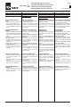
This manual, prepared by the
manufacturer, forms an integral
part of the ATEX rotary valve
supply. It must therefore accompany the rotary valve right up to
its final scrapping, and must be
available ready at hand for quick
consultation by the operators
concerned and those in charge
of operations at the work site. If
the machine changes hands, this
manual must be handed over to
the new owner. Before carrying out any operation on or using the ATEX rotary valve, the
personnel concerned must have
read this manual carefully and
completely. If the manual is lost,
or in such a condition as to make
it illegible, download a new copy
from the TOREX Ò web site, and
check the date of the last revision.
This manual provides warnings
and indications concerning the
safety regulations for preventing accidents at the work site.
However, the operators MUST
scrupulously follow the safety
regulations meant for them according to the existing legislation.
Modifications to the safety regulations made over time must be
integrated and implemented.
Dieses Handbuch, das vom Hersteller erstellt wurde, ist integrierender Teil der Zellenradschleuse ATEX. Daher muss es unbedingt der Zellenradschleuse folgen, bis er demontiert wird, und
leicht zu finden sein, wenn der
Bediener oder die Baustellenleitung in ihm nachschlagen wollen. Bei einem Besitzerwechsel
des Gerätes muss das Handbuch dem neuen Besitzer ausgehändigt wer-den. Bevor das
Betriebspersonal irgendwelche
Arbeiten an oder mit der Zellenradschleuse ATEX ausführt,
muss es dieses Handbuch unbedingt mit großer Aufmerksamkeit durchgelesen haben. Falls
das Handbuch verloren geht
oder unleserlich wird, kann man
sich eine neue Kopie von den
Internetseiten des Herstellers
TOREX® herunterladen, um dann
das Datum der letzten Aktualisierung des Handbuchs zu prüfen.
Dieses Handbuch liefert Hinweise und Angaben zu den Sicherheits- und Unfallverhütungsbestimmungen am Arbeitsplatz. Die
Sicherheitsbestimmungen, die
laut der geltenden Bestimmungen
vom Bedienungspersonal zu beachten sind, müssen auf jeden
Fall immer beachtet werden.
Etwaige Änderungen der Sicherheitsbestimmungen, die im
With the basic features of Laufe der Zeit vorgenommen
the machines as described, werden, sind immer zu erfasthe Manufacturer reserves sen und umzusetzen.
every right to make modifications to parts, details and Der Hersteller behält sich
accessories considered to das Recht vor, unter Beibebe necessary for improving haltung der wesentlichen Eithe product for design or genschaften der beschriecommercial reasons, at any benen Geräte etwaige Ändetime without any obligation rungen an Organen, Teilen
to update the publication und Zubehör vorzunehmen,
imme-diately.
die im Zuge der ProduktverThe latest version of the besserung erforderlich sind
present catalogue is availa- oder aus konstruktiven oder
ble
under kommerziellen Erforderniswww.wamgroup.com
sen heraus ausgeführt werden. Solche Änderungen
können jederzeit vorgenommen werden und verpflichten den Hersteller
nicht, diese Veröffentlichung gleichzeitig auf den
neuesten Stand zu bringen.
Die letzte Version dieses Katalogs steht im Internet unter www.wamgroup.com.
Le présent Manuel, rédigé par le
constructeur, fait partie intégrante de la fourniture de la vanne
rotative ATEX; comme tel il doit
absolument suivre la vanne rotative jusqu’à son démantèlement
et être à portée de la main pour
une consultation rapide de la
part des opérateurs concernés
et par la direction des travaux
du chantier. En cas de changement de propriété de la machine,
le manuel doit être remis au nouveau propriétaire. Avant d’effectuer une quelconque opération
avecou sur la vanne rotative
ATEX, le personnel concerné doit
absolument et obligatoirement
avoir lu très attentivement le présent manuel. Si le manuel est
égaré ou abîmé de manière à ne
plus être lisible, une copie doit
être téléchargée à partir du site
internet de TOREX® en vérifiant
la date de la dernière mise à jour.
Le présent manuel fournit les recommandations et les indications
concernant les consignes de
sécurité pour la prévention contre les accidents du travail. Dans
tous les cas les consignes de
sécurité conformément aux normes en vigueur doivent être observées avec la plus grande attention par les différents opérateurs.
Toutes modifications des consignes de sécurité qui seraient
apportées au fil du temps, doivent être adoptées et appliquées.
Les caractéristiques essentielles des machines décrites demeurant inchangées,
le constructeur se réserve
le droit d’apporter à tout
moment des modifications
aux organes, pièces et accessoires qu’il estimera
avantageuses pour l’amélioration du produit ou pour
des exigences de fabrication ou de commercialisation, sans engagement de
mettre à jour en temps utile
cette publication.
La version toujours mise à
jour du présent catalogue
est disponible sur le site Internet
www.wamgroup.com.
03.07
2
TO.310EX M. 04
Il presente manuale, redatto dal
costruttore, è parte integrante
del corredo della rotovalvola
ATEX; come tale deve assolutamente seguire la rotovalvola fino
al suo smantellamento ed essere facilmente reperibile per una
rapida consultazione da parte
degli operatori interessati e della
direzione lavori del cantiere. In
caso di cambio di proprietà della
macchina il manuale deve essere consegnato alla nuova proprietà. Prima di eseguire qualsiasi operazione con, o sulla rotovalvola ATEX ; il personale interessato deve assolutamente ed
obbligatoriamente aver letto con
la massima attenzione il presente manuale. Qualora il manuale
venga smarrito, sgualcito e tale
da non essere completamente
leggibile, si deve scaricare una
nuova copia dal sito internet della TOREX® e verificarne la data
dell’ultimo aggiornamento. Il presente manuale fornisce avvertenze ed indicazioni relative alle
norme di sicurezza per la prevenzione degli infortuni sul lavoro. Vanno comunque, ed in ogni
caso, osservate con il massimo
scrupolo da parte dei vari operatori le norme di sicurezza poste a loro carico dalle vigenti normative.
Eventuali modifiche delle norme
di sicurezza che nel tempo dovessero aver luogo dovranno
essere recepite ed attuate.
Ferme restando le caratteristiche essenziali delle macchine descritte, il costruttore si riserva il diritto di apportare le eventuali modifiche di organi, dettagli ed accessori che riterrà convenienti per il miglioramento
del prodotto, o per esigenze di carattere costruttivo o
commerciale, in qualunque
momento e senza impegnarsi ad aggiornare tempestivamente questa pubblicazione.
La versione sempre aggiornata del presente catalogo è
reperibile sul sito internet
www.wamgroup.com
RVS • RVC
- WARNING
03.07
- HINWEISE
2
- RECOMMANDATIONS
TO.310EX M. 05
- AVVERTENZE
WARNINGS
HINWEISE
RECOMMANDATIONS
AVVERTENZE
The manufacturer shall be relieved of all responsibility concerning the safety of persons
and objects and operations if the
truck loading and unloading operations, transport, positioning at
the worksite, use, repairs, maintenance are not carried out in
conformity with the instructions
in this manual.
Similarly the manufacturer shall
not be responsible if the rotary
valve is used:
- improperly;
- by unauthorized and/or unskilled personnel;
- with modifications to the original configuration;
- with spare parts that are not
original;
- in a manner non conforming to
existing standards and legisla
tion;
- non conforming to the recom
mendations in this manual or on
the warning and hazard notices on the machine.
The user is obliged to carefully
check that the work area is clear
of obstacles, persons, and machines with potential risk, before
carrying out any operation.
Lifting, transport, installation at
the worksite, set-up, checking
stability and operations, routine
and extraordinary maintenance,
etc. must be carried out by qualified authorized personnel according to the instructions in this
manual and in compliance with
the existing safety regulations.
Der Hersteller betrachtet sich
jeglicher Haftung hinsichtlich der
Sicherheit von Personen, Sachen
und Betrieb enthoben, falls das
Auf- und Abladen vom Lkw,
Transport, Aufstellung auf der
Baustelle, Gebrauch, Reparaturen, Wartung etc. nicht gemäß
der in diesem Handbuch beschriebenen Hinweise ausgeführt werden.
Gleichermaßen betrachtet der
Hersteller sich in keinerlei Weise
verantwortlich, falls die Zellradschleuse wie folgt benutzt wird:
- bestimmungswidrig;
- durch Personal, das nicht befugt und/oder ausreichend angewiesen ist;
- mit Änderungen im Bezug zur
ursprünglichen Konfiguration;
- mit Einbau von Ersatzteilen, die
keine Originale sind;
- nicht entsprechend der augenblicklich geltenden Normen und
Gesetze;
- nicht entsprechend der Empfehlungen dieses Hand buchs
oder der Hinweis- und Warnschilder, die auf der Ma schine
angebracht sind.
Der Anwender ist dazu verpflichtet, vor der Ausführung irgendeines Vorgangs sehr aufmerksam zu prüfen, dass der
Arbeitsbereich frei von Hindernissen, Personen und Maschinen ist, die eine mögliche Gefahrenquelle darstellen.
Heben, Transport, Installation auf
der Baustelle, Inbetriebnahme,
Standsicherheits- und Funktion
stests, regelmäßige und außeror dentliche Wartung etc. müssen durch qualifiziertes und befugtes Personal vorgenommen
werden, das gemäß der Anweisungen, die in diesem Handbuch
stehen, und unter Beachtung der
geltenden Sicherheitsbestim
mungen vorzugehen hat.
Le constructeur se considère
dégagé de toute responsabilité
concernant la sécurité des personnes, des choses et du fonctionnement si les opérations de
chargement et de déchargement
du camion, transport, positionnement sur chantier, utilisation,
réparations, entretiens, etc. n’ont
pas été effectuées conformément aux recommandations décrites dans cette notice d’instructions.
De même le constructeur ne
pourra être considéré responsable si la vanne est utilisée :
- de manière impropre;
- par du personnel non autorisé
et/ou pas suffisamment formé;
- avec des modifications par rapport à la configuration originale;
- avec introduction de pièces détachées non d’origine ;
- de manière non conforme à la
réglementation et à la législation en vigueur ;
- de manière non conforme aux
recommandations fournies
dans la présente notice ou par
les plaques signalétiques apposées sur la machine.
L’utilisateur a l’obligation de vérifier avec la plus grande attention, avant d’effectuer une quelconque opération, que la zone
de travail est dégagée de tout
obstacle, personnes, machines
pouvant représenter une source potentielle de danger.
Les opérations de soulèvement,
le transport, le montage sur chantier, la mise en service, les vérifications de stabilité et de fonctionnement, les entretiens ordinaires et extraordinaires, etc.
doivent être effectuées par du
personnel qualifié et autorisé,
lequel doit intervenir suivant les
indications indiquées dans la
présente notice d’instructions et
dans le respect des normes de
sécurité en vigueur.
Il costruttore si riterrà sollevato
da qualsiasi responsabilità inerente la sicurezza delle persone, delle cose e di funzionamento qualora le operazioni di carico
e scarico da autocarro, trasporto, posizionamento in cantiere,
utilizzo, riparazioni, manutenzioni, ecc. non siano eseguite conformemente alle avvertenze descritte nel presente manuale.
Analogamente il costruttore non
si riterrà in alcun modo responsabile qualora la rotovalvola venga utilizzata:
- impropriamente;
- da personale non autorizzato
e/o non sufficientemente addestrato;
- con modifiche rispetto alla configurazione originale;
- con inserimento di parti di ricambio non originali;
- non conformemente alla normativa e legislazione attualmente vigente;
- non conformemente a quanto
raccomandato nel presente
manuale o sulle targhette di avvertenza e pericolo applicata
sulla macchina.
Per l’utente è fatto obbligo di verificare con la massima attenzione, prima di eseguire qualsiasi
operazione, che la zona di lavoro sia libera da ostacoli, persone, macchine potenziali fonti di
pericolo.
Le operazioni di sollevamento,
trasporto, installazione in cantiere, la messa in funzione, le verifiche di stabilità e funzionamento, le manutenzioni ordinarie e
straordinarie,ecc., devono essere svolte da personale qualificato ed autorizzato, il quale deve
operare secondo le indicazioni
riportate nel presente manuale e
nel rispetto delle vigenti norme di
sicurezza.
When positioning the machine at
the worksite, it must be earthed.
- It is forbidden to remove the
guards and safeties present on
the machine.
- Before start-up make sure all
the guards have been installed
correctly.
Vor jedem Eingriff ist es unbedingt erforderlich, alle elektrischen Verbindungen der Maschine abzuklemmen.
- Es ist verboten, die Schutzund Sicherheitseinrichtungen,
die auf der Maschine vorhanden sind, zu entfernen.
- Vor dem Einschalten sicherstellen, dass alle Schutzvorrichtungen korrekt installiert worden sind.
Avant toute opération il est obligatoire de débrancher toutes les
alimentations électriques de la
machine.
- Il est interdit d’enlever les protections et les sécurités présentes sur la machine.
- Avant la mise en marche s’assurer que toutes les protections sont installées correctement.
Prima di ogni operazione è obbligatorio scollegare tutte le alimentazioni elettriche della macchina.
- É vietato rimuovere le protezioni e le sicurezze presenti sulla
macchina.
- Prima dell’ avviamento assicurarsi che tutte le protezioni siano correttamente installate.
RVS • RVC
- WARNING
03.07
- HINWEISE
2
- RECOMMANDATIONS
TO.310EX M. 06
- AVVERTENZE
E’ VIETATO
IT IS FORBIDDEN
VERBOTEN IST
IL EST INTERDIT
• to use the Valve without the • die Schleuse ohne die in der • d’utiliser la machine sans les • l’uso della macchina priva dei
guards and safety devices list- Betriebsanleitung angegebe- dispositifs de protection et de dispositivi di protezione e di sied in the manual,
nen Schutz- und Sicherheits- sécurité énumérés dans le pré- curezza elencati nel seguente
manuale,
vorrichtungen in Betrieb zu sent manuel,
nehmen,
• d’utiliser la machine en présen- • l’uso della macchina qualora si
• to use thethe Valve if it has noticeable operating defects (ex- • die Inbetriebnahme bei einem ce d’anomalies de fonctionne- manifestino anomalie apprezcessive noise, vibrations, etc.), klar gestörten Lauf (erhöhte ment (machine trop bruyante - zabili nel funzionamento della
vibrations - etc.),
stessa (eccessiva rumorosità
Geräusche, Vibrationen etc.),
- vibrazioni - ecc.),
• to use it after repair, servicing • die Wiederinbetriebnahme des • d’utiliser la machine après les
or maintenance work without Geräts nach einer Reparatur interventions de réparation et/ • l’uso della macchina dopo infirst carrying out the test und/oder Wartungsarbeiten, ou de maintenance sans terventi di riparazione e/o maschedule detailed on page ohne die auf Seite M.35 ge- d’abord avoir effectué le con- nutenzione senza avere rifatto i controllo di cui alla pag.M.35.
M.35.
nannten Kontrollen vorgenom- trôle indiqué à la page M.35.
men zu haben.
- If the outlet spout IS NOT connected to a material conveyor
system, the rotor can be
reached through the outlet; this
is why:
„IT IS ABSOLUTELY FORBIDDEN TO INSERT THE HAND OR
OBJECTS INTO THE OUTLET
SPOUT“.
- Wenn der Auslauf NICHT an irgendein System zur Materialbeförderung angeschlossen
wird, ist es möglich, durch diesen den Rotor zu erreichen.
Aus diesem Grund ist es:
„ABSOLUT VERBOTEN, IRGENDETWAS, HÄNDE, GEGENSTÄNDE etc. IN DEN AUSLAUF
EINZUFÜHREN.“
- Si la bouche de déchargement
N’EST reliée à aucun système
de convoyage du produit, il est
possible, par la bouche ellemême, d’atteindre le rotor ; c’est
pourquoi :
« IL EST ABSOLUMENT INTERDIT D’INTRODUIRE QUOI QUE
CE SOIT - MAINS - OBJETS DANS LA BOUCHE DE DÉCHARGEMENT ».
- Se la bocca di scarico NON viene collegata a nessun sistema
di convogliamento del materiale, è possibile attraverso questa, raggiungere il rotore; per
questo motivo è:
“ASSOLUTAMENTE VIETATO
INTRODURRE QUALSIASI
COSA - MANI - OGGETTI NELLA BOCCA DI SCARICO”.
Valve installation must always be done in such a way
as to prevent the operator
from touching the moving
rotor.
Die Zellenradschleuse ist
immer so einzubauen, dass
der Bediener daran gehindert wird, das laufende Zellenrad zu berühren.
L’installation de la vanne doit
être faite de manière à toujours empêcher l’opérateur
de toucher le rotor en mouvement.
L’installazione della valvola
deve sempre essere tale da
impedire all’operatore di
toccare il rotore in movimento.
Installation of the valve must
also be done in such a way
as to make it possible to
reach the rotor only when
the valve is set in safety
conditions. (see page M.13)
Die Zellenradschleuse ist
außerdem so einzubauen,
dass man das Zellenrad nur
dann erreichen kann, wenn
die Zellenradschleuse sich
im sicheren Zustand befindet (siehe Seite M.13)
L’installation de la vanne doit
en outre permettre d’atteindre le rotor seulement
quand la vanne est placée en
conditions de sécurité. (voir
page M.13)
l’installazione della valvola
deve essere inoltre tale da
consentire il raggiungimento del rotore solo quando la
valvola è posta in condizioni
di sicurezza (vedi pag. M.13)
RVS • RVC
- WARNING
03.07
- HINWEISE
2
- RECOMMANDATIONS
TO.310EX M. 07
- AVVERTENZE
GENERAL PROHIBITIONS AND
REGULATIONS
• This equipment must not be
used even partially by unauthorised personnel.
• The shop foreman or department manager is responsible
for machine operator training
and for checking training level
achieved.
• The machine must not be used
for purposes other than those
is was designed for.
• Read carefully the warning notices attached to the machine.
• Do not remove the warning notices attached to the machine.
• When the machine is running,
do not service, repair, regulate
the machine or carry out any
other operation not strictly required by the work cycle. Before any of the above listed operations, always disconnect
the machine from all electric
power supply sources.
• Do not remove the guards and
the safety devices on the machine.
• Do not start to work with protections opened or do not open
them during the work.
- Before startup, make sure all
the guards are installed correctly.
• Always wear safety gloves
when working on the machine.
• At the end of the work shift,
disconnect the machine from
the electric and hydraulic supply.
• Any repair, service or maintenance work, whether electrical or otherwise.
The equipment must not be started before the the plant it is going
to be installed in, has been declared in conformity with the European Directive machine:
CEI EN 60204-1
UNI EN 1037
UNI EN 1088
UNI EN 953
ALLGEMEINE VORSCHRIFTEN
• Jegliche auch teilweise Bedienung des Geräts durch hierzu
nicht ausdrücklich autorisiertes
Personal ist untersagt.
• Der Betriebsleiter ist dafür verantwortlich, daß das zur Bedienung autorisierte Personal
in der Bedienung des Geräts
geschult wird.
• Das Gerät darf zu keinem anderen Zweck als zu dem in diesem Handbuch beschriebenen
verwendet werden.
• Die Gefahren- und Hinweisschilder an der Maschine müssen beachtet werden.
• Es ist verboten, die Gefahrenund Hinweisschilder an der
Maschine zu entfernen.
• Wartungs-, Reparatur-, und/
oder vom Hersteller autorisierte Änderungsarbeiten dürfen
nicht bei laufendem Gerät
durchgeführt werden. Vor der
Durchführung solcher Arbeiten
muß zuerst die Stromversorgung zum Gerät unterbrochen
werden.
• Es ist verboten, die an der Maschine angebrachten Schutzund Sicherheitseinrichtungen
zu entfernen.
• Schutzeinrichtungen am Gerät
dürfen bei Kontroll-, Wartungs,Reparatur- und/oder Änderungsarbeiten weder fehlen
noch während dieser Arbeiten
entfernt werden.
- Vor der Inbetriebnahme sicherstellen, dass alle Schutzvorrichtungen korrekt installiert
sind.
• Nur mit Schutzhandschuhen
am Gerät arbeiten.
• Bei Betriebsende immer die
Stromzufuhr oder, falls vorhanden, den Hydraulikkreislauf abschalten.
• Für alle elektrischen und nicht
elektrischen Wartungsarbeiten
die Vorschriften der Normen:
CEI EN 60204-1
UNI EN 1037
UNI EN 1088
UNI EN 953 beachten.
PRESCRIPTIONS ET
CONSIGNES GENERALES
• L’utilisation, même partielle, de
l’équipement de la part du personnel non autorisé est expressément interdit.
• Le chef d’usine et les chefs
d’atelier ont l’obligation d’instruire et de contrôler le personnel préposé à l’utilisation de
l’équipement.
• L’utilisation de l’équipement
pour des usages différents de
ceux pour lesquels il a été prévu sont interdits.
• Llire attentivement les plaques
signalétiques et de danger apposées sur l’équipement.
• Il est interdit d’enlever de l’équipement les plaques de signalisation et de danger.
• Il est interdit d’effectuer la maintenance, réparer, modifier ou
de faire tout ce qui n’est pas
strictement nécessaire au cycle de travail quand la machine
est en marche.
• Il est interdit de démonter les
protections et les sécurités
présentes sur la machine.
• Il est interdit de commencer le
travail avec les protections
ouvertes ou de les ouvrir pendant le travail.
- Avant la mise en marche s’assurer que toutes les protections sont montées correctement.
• Le port des gants de protection est obligatoire pour travailler sur la machine.
• A la fin des périodes de travail
débrancher toujours la machine des alimentations électriques et hydrauliques.
• Toute maintenance électrique et
autre doit être conforme aux
normes:
CEI EN 60204-1
UNI EN 1037
UNI EN 1088
UNI EN 953
PRESCRIZIONI
E DIVIETI GENERALI
• E’ vietato l’uso, anche parziale, dell’attrezzatura da parte del
personale non espressamente autorizzato.
• L’istruzione del personale preposto all’uso è da realizzare e
verificare a cura del capo officina e dei capi reparto.
• E’ vietato l’uso dell’attrezzatura per modalità diverse da quelle per cui è stata prevista.
• Leggere con attenzione le targhe di avvertenza e pericolo
poste sulla macchina.
• E’ vietato rimuovere le targhe
di avvertenza e pericolo dalla
macchina.
• E’ vietato manutenzionare, eseguire riparazioni, modifiche e
quanto non strettamente necessario al ciclo di lavoro con
la macchina in movimento. Prima di tutto è obbligatorio disinnestare tutte le alimentazioni
elettriche alla macchina.
• E’ vietato rimuovere le protezioni e le sicurezze presenti
sulla macchina.
• E’ vietato iniziare il lavoro con
le protezioni aperte o aprirle
durante il lavoro.
- Prima dell’ avviamento assicurarsi che tutte le protezioni siano correttamente installate.
• Operare sulla macchina solo
con i guanti di protezione.
• Al termine dei periodi di lavoro
scollegare sempre la macchina dalle alimentazioni elettriche
e idrauliche.
• Qualsiasi manutenzione elettrica e non elettrica deve attenersi alle norme :
CEI EN 60204-1
UNI EN 1037
UNI EN 1088
UNI EN 953
The equipment must also
not be started up unless the
machine/plant in which it is
to be installed is declared as
conforming to the provisions
of Machine Directive (98/37/
CE) of 22/06/1998.
Das Gerät darf nicht in Betrieb genommen werden,
bevor die Maschine/Anlage,
in die es eingebaut wird,
den Bestimmungen der Maschinen-Richtlinie 98/37/EG
vom 22.06.1998 konform erklärt worden ist.
En outre il est interdit de les
mettre en fonction avant que
la machine/ l’installation
dans laquelle elles doivent
être montées a été déclarée
conforme aux dispositions
de la Directive machine 22/
06/1998 (98/37/CE).
E’ Inoltre vietato metterle in
funzione prima che la macchina/impianto nel quale devono essere installate sia
dichiarato conforme alle disposizioni della direttiva
macchine del 22/06/1998 (98/
37/CE).
RVS • RVC
- WARNING
03.07
- HINWEISE
2
- RECOMMANDATIONS
TO.310EX M. 08
- AVVERTENZE
PROTECTIVE DEVICES TO BE DURCH DEN MONTEUR VORZU- PROTECTIONS A RÉALISER PROTEZIONI DA REALIZZARE
A CURA DELL’INSTALLATORE
PROVIDED BY THE INSTALLER SEHENDE SCHUTZVORRICH- PAR L’INSTALLATEUR
TUNGEN
- If the valve’s outlet is not cov- - Wenn am Auslauf der Schleuered, it is a potential danger se kein weiterführendes Förzone that must be highlighted dergerät angebaut ist, stellt das
with suitable danger notices.
freiliegende Zellenrad eine poIf necessary access to the tentielle Gefahr für das Bediarea should be restricted by enerper-sonal dar. Es ist in diesuitable means (owner res- sem Fall die Aufgabe des Beposibility).
treibers, Gefahrenhinweise di- If the machine is used with very rekt am Gerät anzubringen sohot materials, such that the wie den Gefahrenbereich
surface temperature exceeds besonders zu kennzeichnen
60ºC, the installer must insu- und gegen Betreten zu silate the rotary valve or install chern.
mechanical barriers to prevent - Falls das Gerät für Stäube veroperators from touching hot wendet wird, die eine hohe
parts.
Temperatur aufweisen, so
The necessary warning notic- dass die Oberfläche sich auf
es or pictograms must also be mehr als 60° C erwärmen kann,
affixed.
muss man die Zellenradschleuse isolieren oder mechanische
It is the installer’s responsibility Barrieren installieren, die es
to provide all the warning notic- unmöglich machen, dass das
es and position the warning Personal mit jenen Teilen in Beplates to inform the operators of rührung kommt. Außerdem ist
the need to use P.P.E. and the es erforderlich, die notwendipotential hazards present on the gen Schilder bzw. Bildaufklerotary valve during normal use, ber anzubringen.
in the event of failure, during
maintenance, installation or re- Der Installateur hat für die Bemoval of the valve. See Page reitstellung aller Schilder und die
Anbringung der Warnschilder zu
M.43".
sorgen, welche das Betriebspersonal darauf hinweisen, dass
es erforderlich ist, PSA zu verwenden und sie auf die möglichen Gefahren hinweisen, die
an der Zellenradschleuse sowohl beim normalen Gebrauch,
bei Störungen, bei der Wartung,
dem Einbau oder Ausbau der
Schleuse vorkommen können.
Siehe Seite M.43".
- Si l’orifice de refoulement de la - Se la bocca di scarico della
vanne n’est pas relié, il repré- macchina non è collegata, rapsente un danger potentiel. Il presenta un potenziale pericofaut mettre la zone en éviden- lo, bisogna evidenziare la zona
ce par des panneaux de signa- con opportuna cartellonistica
lisation montés sur la machine sulla macchina ed eventualet éventuellement interdire l’ac- mente interdire la zona con
cès à cette zone par des opportuni sistemi (fatto da utimoyens appropriés (à la char- lizzatore).
- In caso di utilizzo della macchige de l’utilisateur).
- En cas d’utilisation de la ma- na con materiali molto caldi, tali
chine avec des matières très che la temperatura superficiachaudes telles que la tempéra- le superi i 60°, l’installatore doture superficielle dépasse 60°, vrà provvedere a coibentare la
l’installateur devra calorifuger rotovalvola o ad installare barla vanne rotative ou prévoir des riere meccaniche che impedibarrières empêchant le per- scono al personale di raggiunsonnel d’entrer en contact avec gere le parti calde. Ed inoltre
les parties chaudes. Et en outre dovrà apporre la necessaria
il devra apposer les panneaux cartellonistica o pittogrammi.
ou pictogrammes de signalisaE’ a cura dell’installatore prevetions.
dere tutta la cartellonistica ed il
L’installateur doit prévoir la signa- posizionamento delle targhe molisation et l’emplacement des pla- nitorie che segnalino agli operaques d’avertissement qui signa- tori la necessità di utilizzo dei D.P.I
lent aux opérateurs la nécessité ed i pericoli potenzialmente pred’utiliser des E.P.I et les dangers senti sulla rotovalvola sia in fase
que peut représenter la vanne di normale utilizzo, avaria, marotative dans la phase d’utilisa- nutenzione, installazione o rimotion, panne, entretien, installation zione della valvola. Vedi
ou dépose. « Voir Page M.43 ». Pag.M.43".
FEATURES OF POWDERS HANDLED
The installer must enclose
with the Manufacturer’s documentation the form filled in
by the customer regarding
the powders to be handled,
and hand these over to the
customer, so that the safety
precautions specific to the
powders handled are indicated every time the rotary
valve is used.
EIGENSCHAFTEN DER BEHANDELTEN SCHÜTTGÜTER
Der Monteur muss der Dokumentation des Herstellers die vom Kunden mit den
Eigenschaften der zu behandelnden Stäube ausgefüllte
Karte beilegen und alles dem
Kunden aushändigen, damit
während der Eingriffe an der
Zellenradschleuse die spezifischen für die behandelten Stäube geltenden Vorsichtsmaßnahmen angegeben sind.
CARACTERISTIQUES DES
POUSSIËRES TRAITÉES
L’installateur devra joindre à
la documentation du Constructeur, la fiche des caractéristiques des matières à
traiter rédigée par le Client
et remettre le tout à ce
même client. De cette manière, pour chaque intervention
sur la vanne rotative seront
indiquées les consignes de
sécurité spécifiques des
poudres traitées.
CARATTERISTICHE DELLE
POLVERI TRATTATE
L’installatore dovrà allegare
assieme alla documentazione del Costruttore, la scheda compilata del Cliente sulle caratteristiche delle polveri da trattare, e consegnare il tutto al cliente stesso in
modo tale che durante ogni
intervento alla rotovalvola
siano indicate le precauzioni di sicurezza specifiche
delle polveri trattate.
The features of the powders
handled and the process temperature must be specified by
the client at the time of placing
the order (see Table below).
Es ist sehr wichtig, dass der
Kunde bei der Bestellung die Eigenschaften der zu behandelnden Stäube angibt und auch die
Prozesstemperaturen, siehe die
folgende Tabelle.
Dans la phase de commande il
est important que le client spécifie les caractéristiques des poudres à traiter ainsi que les températures du processus, voir
tableau ci-dessous.
E’ importante da parte del cliente
in fase d’ordine specificare le
caratteristiche delle polveri da
trattare e anche le temperature
di processo, vedi tabella seguente.
RVS • RVC
- WARNING
03.07
- HINWEISE
2
- RECOMMANDATIONS
TO.310EX M. 09
- AVVERTENZE
POWDERS - STAUB- POUDRE- POLVERE
Parameter - Parameter
Paramètre - Parametro
Unit of measurement- Maßeinheit
Unità di misura - Unità di misura
Value - Wert - Valeur- Valore
Description of powder- Staubbeschreibung Description poudree - Descrizione polvere
Grain size (Average, D50) - Körngröße (Durchschnitt, D50)
Granulométrie (Moyenne, D50) - Granulometria (Media, D50)
Kst
µm
bar m/s
Minimum ignition temperature of a 5 mm layer of dust (GT)
Mindestzündtemperatur einer Staubschicht von 5 mm (GT)
Température minimum d'inflammation d'une couche de poudre de 5 mm (GT)
Temperatura minima di ignizione di uno strato di polvere di 5 mm (LIT)
°C
Minimum ignition temperature of suspended dust (MIT)
Mindestzündtemperatur des schwebenden Staubs (MIT)
Température minimum d'inflammation poudre en suspension (MIT)
Temperatura minima di ignizione di polvere sospesa (MIT)
°C
Lowest explosion limit (LEL)
Mindestkonzentration zur Explosion (LEL)
Concentration minimum d'explosion (LEL)
Concentrazione minima di esplosione (LEL)
g/m3
Minimum ignition energy (MIE)
Mindestzündenergie (MIE)
Energie minimum d'ignition (MIE)
Energia minima di ignizione (MIE)
mJ
Maximum explosion pressure (Pmax)
Max. Explosionsdruck (Pmax)
Pression maximum d'explosion (Pmax)
Pressione massima di esplosione (Pmax)
bar
Limit of oxygen concentration (LOC)
Sauerstoffgrenzkonzentration (LOC)
Concentration limite d'oxygène (LOC)
Concentrazione limite di ossigeno (LOC)
% by volum
Surface resistivity - Oberflächenwiderstand
Résistivité superficielle - Resistività superficiale
Gohm x m
Classification of powder - Klassifikation des Staubs
Classement de la poudre - Classificazione della polvere
ATEX Classification required-Group-Category - Klassifikation ATEX verlangt
Classificazione ATEX richiesta- Classificazione ATEX richiesta
Reduced pressure (Pred)- Reduzierter Druck (Pred)
Pression réduite (Pred) - Pressione ridotta (Pred)
ST1
Gruop - Gruppe
Groupe - Gruppo
ST2
ST3
Category - Kategorie
Dust or Gas
Catégorie - Categoria
bar
GENERAL DATA- ALLGEMEINE DATEN - CARACTÉRISTIQUES GÉNÉRALES - DATI GENERALI
Air flow rate- Luftfördermenge
Débit d'air - Portata d'aria
m3/h
Specific weight - Spez. Gewicht
Poids spécifique - Peso specifico
kg/
Humidity - Feuchtigkeit - Humidité - Umidità
%
Ambient temperature - Umgebungstemperatur
Température ambiante - Temperatura ambiente
°C
Corrosive components - Korrosive Komponenten
Composants corrosifs - Componenti corrosivi
Acidity - Säurewert - Acidité - Acidità
Ph
≤ Tamb ≤
RVS • RVC
- INDICATIONS FOR THE USE
03.07
- ANGABEN ZUM GEBRAUCH
2
- MODES D’EMPLOI
- INDICAZIONI PER L’USO
TO.310EX M. 10
- The ATEX version of the - Die ATEX-Version der Zelrotary valve is designed for lenradschleuse ist dazu
handling powders that do entwickelt worden, mit
not release explosive gas- Stäuben zu arbeiten, die
während der Dosierung
es during batching.
keine als explosiv zu betrachtenden Gase entwickeln.
The rotary valve described Die in diesem Handbuch beZellenradin this manual is designed schriebene
and tested for use in a po- schleuse ist für den Einsatz
tentially explosive area clas- in explosionsgefährdeten
sified as area 22 or unclassi- Bereichen mit Klassifikation
fied areas in accordance with als 22 oder nicht klassifizierDirective 94/9/CE. The pow- ten Bereichen gemäß der
ders handled must have ex- Norm 94/9/EG entwickelt und
plosiveness index St1 or St2 getestet worden. Die behanStäube
müssen
and this value must be com- delten
municated to TOREX ® at the Staubexplosionsindexe St1
time of placing the order to oder St2 haben und diese
allow correct choice of the müssen der Firma TOREX ®
machine.
bei der Bestellung mitgeteilt
werden, um die korrekte
Auslegung der Maschine zu
ermöglichen.
- La version ATEX de la van- - La versione ATEX della rone rotative a été conçue tovalvola è stata progettapour travailler avec des ta per operare con polveri
poudres qui, pendant le che durante il trattamento
traitement de dosage, ne di dosaggio non rilascino
dégagent pas de gaz con- gas considerati esplosivi.
sidérés explosifs.
La vanne rotative décrite
dans ce manuel a été conçue et testée pour être utilisée dans les environnements explosibles classés
comme zone 22 conformément aux normes de la directive 94/9/CE.
Les poudres traitées doivent avoir des indices d’explosivité St1 ou St2 et elles
doivent être communiquées
à TOREX ® au moment de la
commande pour un choix
correct de la machine.
La rotovalvola descritta in
questo manuale è stata progettata e testata per un utilizzo in zone potenzialmente esplosive classificate
come 22 o non classificate
secondo le norme 94/9/CE.
Le polveri trattate dovranno
avere indici di esplosività St1
o St2 e devono essere comunicate alla TOREX® al momento dell’ordine per una
scelta corretta della macchina.
*IMPORTANT NOTE:
FOR THE RVS MODEL, THIS
DEFINITION (SEE FIG. BELOW)
IS ONLY APPLICABLE IF THE
VENT PLUGS ON THE ROTARY
VALVE BODY ARE CONNECTED TO A CONVEYOR SYSTEM
WHICH GUARANTEES THE ABSENCE OF DUST CLOUDS IN
THE AIR NEAR THE VALVE.
IF THIS IS NOT THE CASE, THE
USER MUST PROVIDE A LOCALIZED EXTRACTION SYSTEM THAT GUARANTEES
CLASSIFICATION OF THE
AREA OUTSIDE THE RVS AS
22.
*REMARQUE IMPORTANTE :
POUR LE MODELE RVS, CETTE DEFINITION (VOIR FIG. CICONTRE) N’EST VALABLE QUE
SI LES BOUCHONS D’ÉVENT
PRÉVUS SUR LE CORPS DE LA
VANNE ROTATIVE SONT RELIÉS A UN SYSTEME DE CONVOYAGE ASSURANT L’ABSENCE DE NUAGES DE POUSSIERE
DISPERSÉS DANS L’AIR A
PROXIMITÉ DE LA VANNE
ELLE-MEME. EN ALTERNATIVE
L’UTILISATEUR DEVRA AVOIR
RECOURS A UN SYSTEME
D’ASPIRATION LOCALISÉ GARANTISSANT LA CLASSIFICATION DE LA ZONE EXTERIEURE
A LA RVS COMME ZONE 22.
*NOTA IMPORTANTE:
PER IL MODELLO RVS QUESTA
DEFINIZIONE (VEDI FIG. RIPORTATA DI SEGUITO) VALE SOLO
SE I TAPPI DI SFIATO SUL CORPO DELLA ROTOVA LVOLA
SONO COLLEGATI AD UN SISTEMA DI CONVOGLIAMENTO
CHE GARANTISCA L’ASSENZA DI NUVOLE DI POLVERE
AERO DISPERSE IN PROSSIMITA’ DELLA VALVOLA STESSA.
IN ALTERNATIVA L’UTILIZZATORE DOVRA’ PROVVEDERE
ALL’UTILIZZO DI UN SISTEMA
DI ASPIRAZIONE LOCALIZZATO CHE GARANTISCA LA
CLASSIFICAZIONE DELLA
ZONA ESTERNA ALL’ RVS
COME 22.
*WICHTIGER HINWEIS:
FÜR DAS MODELL RVS GILT
DIESE DEFINITION (SIEHE ABB.
HIER UNTEN) NUR DANN, WENN
DIE ENTLÜFTUNGSSTOPFEN
AUF DEM GEHÄUSE DER ZELLENRADSCHLEUSE AN EIN BEFÖRDERUNGSSYSTEM ANGESCHLOSSEN SIND, DAS GARANTIERT; DASS IN DER NÄHE
DER ZELLENRADSCHLEUSE
KEINE IN DER LUFT VERTEILTEN STAUBWOLKEN ENTSTEHEN. IN ALTERNATIVE MUSS
DER ANWENDER FÜR DIE BENUTZUNG EINES LOKALISIERTEN ABSAUGSYSTEMS SORGEN, DAS DIE KLASSIFIZIERUNG DES AUSSENBEREICHS
DER RVS ALS 22 GEWÄHRLEISTET.
RVS • RVC
- INDICATIONS FOR THE USE
03.07
- ANGABEN ZUM GEBRAUCH
2
- MODES D’EMPLOI
- INDICAZIONI PER L’USO
TO.310EX M. 11
THE ROTARY VALVES OF THE DIE ZELLENRADSCHLEUSEN LES VANNES ROTATIVES DE LE ROTOVA LVOLE DELLA
RVS/C ATEX RANGE ARE NOT DER MODELLREIHE RVS/C LA GAMME RVS/C ATEX NE GAMMA RVS/C ATEX NON
FLAME RESISTANT.
ATEX SIND NICHT DRUCKFEST. SONT PAS RESISTANTES A LA SONO A TENUTA FIAMMA
FLAMME
The user must ensure that
the plant in which the rotary
valve is to be installed is set
in safety condition from the
explosion risk point of view
before it is started up and
the „Document for protection from explosion“ is
drafted as per the provisions
of ATEX Directive 99/92/CE.
Der Anwender muss sicherstellen, dass die Anlage, in
der die Zellenradschleuse
installiert wird, unter dem
Gesichtspunkt der Explosionsgefahr angemessen in
den sicheren Zustand gebracht worden ist, bevor sie
in Betrieb genommen wird
und dass außerdem das „Explosionsschutzpapier“ aufgestellt worden ist, das nach
der ATEX-Richtlinie 99/ 92/EG
vorgesehen ist.
L’utilisateur devra s’assurer
que l’équipement dans lequel sera installée la vanne
rotative a été mis en sécurité du point de vue des risques d’explosion avant la
mise en marche et que le
« document sur la protection
contre les explosions » a été
rédigé comme prévu par la
Directive ATEX 99/92/CE.
L’utilizzatore dovrà assicurarsi che l’impianto all’interno del quale verrà installata
la rotovalvola sia stato adeguatamente messo in sicurezza da un punto di vista di
rischio esplosione prima di
essere avviato e che inoltre
sia stato redatto il “documento sulla protezione contro le esplosioni” come previsto dalla Direttiva ATEX 99/
92/CE.
RVS • RVC
- INDICATIONS FOR THE USE
03.07
- ANGABEN ZUM GEBRAUCH
2
- MODES D’EMPLOI
- INDICAZIONI PER L’USO
TO.310EX M. 12
The rotary valve has been designed and tested for use in external zone classified as 22 or
non classified zones and with
process atmospheres (inside the
valve) classified as ZONE 20 in
accordance with Directive 94/9/
EC and 1999/92/EC.
Die in diesem Handbuch beschriebene Zellenradschleuse
wurde für den Einsatz in explosionsgefährdeten Bereichen
entwickelt und getestet, die in
Übereinstimmung mit der
Richtlinie 94/9/EG und 1999/92/
EG als 22 eingestuft oder nicht
eingestuft sind und mit
Prozessatmosphäre (Schleuseninneres), die als ZONE 20
eingestuft ist.
La vanne rotative a été conçue
et réalisée pour être utilisée dans
une zone à l’extérieur classée
comme zone 22 ou non classée
et avec atmosphères de procédés (intérieur de la vanne) classées comme ZONE 20 conformément à directive 94/9/CE et
1999/92/CE.
La rotovalvola è stata progettata e
realizzata per utilizzo in zona
esterna classificata come 22 o
non classificata e con atmosfere
di processo (interno della valvola)
classificate come ZONA 20 in accordo alla Direttiva 94/9/CE e
1999/92/CE.
The rotary valve is designed and
constructed in such a manner
as to avoid abnormal overheating during operation. In order to
operate in safe conditions, it is
necessary to ensure that the
powder handled has a minimum ignition temperature
greater than the temperature value indicated on the
rating plate.
Die Zellenradschleuse wurde so
entwickelt und konstruiert, dass
es beim Betrieb nicht zu anomalen Erhitzungen kommen kann.
Um unter sicheren Verhältnissen
zu arbeiten, ist sicherzustellen, dass die Entzündungstemperatur der behandelten
Stäube über dem auf dem
Typenschild angegebenen
Wert liegt.
La vanne rotative a été conçue et
construite de manière à ne pas
provoquer des surchauffes
anormales pendant le fonctionnement. Pour pouvoir travailler
dans les conditions de sécurité
il faut vérifier que les poudres traitées aient une température d’ignition plus haute que la valeur de la température indiquée sur la plaque.
La rotovalvola è stata progettata e
costruito in modo tale da non provocare surriscaldamenti anomali
durante il funzionamento. Per poter operare in condizioni di sicurezza occorre verificare che le
polveri trattate abbiano la minima temperatura di ignizione
superiore al valore di temperatura indicato sulla targhetta.
- The rotary valve must be in- - Die Zellenradschleuse muss -la vanne rotative devra être
stalled with sufficient clear- so eingebaut werden, dass montée avec un espace suffiance around it to allow for nor- ringsum ausrei-chend Platz sant tout autour pour effectuer
mal assembly/disassembly, vorhanden ist, um die norma- les opérations ordinaires de
cleaning and maintenance op- len Ein- und Ausbauarbeiten, montage/démontage, nettoyaerations.
die Reinigung und die Wartung ge et entretien.
vornehmen zu können.
- If the machine is used with very - Falls das Gerät für Stäube ver- - En cas d’utilisation de la mahot materials, such that the wendet wird, die eine hohe chine avec des matières très
surface temperature exceeds Temperatur aufweisen, so chaudes telles que la tempéra60ºC, the installer must insu- dass die Oberfläche sich auf ture superficielle dépasse 60°,
late the rotary valve or install mehr als 60° C erwärmen kann, l’installateur devra calorifuger
mechanical barriers to prevent muss man die Zellenradschleu- la vanne rotative ou prévoir des
operators from touching hot se isolieren oder mechanische barrières empêchant le perparts.
Barrieren installieren, die es sonnel d’entrer en contact avec
The necessary warning notic- unmöglich machen, dass das les parties chaudes. Et en outre
es or pictograms must also be Personal mit jenen Teilen in Be- il devra apposer les panneaux
rührung kommt. Außerdem ist ou pictogrammes de signalisaaffixed.
es erforderlich, die notwendi- tions.
gen Schilder bzw. Bildaufkleber anzubringen.
- la rotovalvola dovrà essere installata con uno spazio circostante sufficiente per effettuare le normali operazioni di montaggio/smontaggio, pulitura e
manutenzione.
- In caso di utilizzo della macchina con materiali molto caldi, tali
che la temperatura superficiale superi i 60°, l’installatore dovrà provvedere a coibentare la
rotovalvola o ad installare barriere meccaniche che impediscono al personale di raggiungere le parti calde. Ed inoltre
dovrà apporre la necessaria
cartellonistica o pittogrammi.
RVS • RVC
- INDICATIONS FOR THE USE
03.07
- ANGABEN ZUM GEBRAUCH
2
- MODES D’EMPLOI
- INDICAZIONI PER L’USO
TO.310EX M. 13
Before carrying out any operation on the machine,
make sure it is in safety condition.
Bevor man irgendeinen Eingriff auf der Maschine ausführt, sicherstellen, dass
diese sich im sicheren Zustand befindet.
Avant d’effectuer une quelconque intervention sur la
machine, s’assurer qu’elle a
été mise en sécurité.
Prima di effettuare un qualsiasi intervento sulla macchina assicurarsi che questa
sia messa in sicurezza.
IMPORTANT: In this manual we
shall use the phrase „setting
the machine in safety condition“ to indicate the following
operations:
WICHTIG: Im weiteren Text dieses Handbuchs verstehen wir
unter dem Begriff „die Maschine in den sicheren Zustand
bringen“ die folgenden Vorgänge:
IMPORTANT : Dans la suite du
présent manuel nous indiquons
avec la mention „mettre en
sécurité la machine“ les opérations suivantes :
IMPORTANTE: In seguito nel
presente manuale indicheremo
con la dicitura “mettere in sicurezza la macchina” le seguenti operazioni:
- S’assurer que la machine
est débranchée de toutes
les alimentations électriques.
- S’assurer que la machine
est complètement arrêtée.
- Attendre que la température à l’intérieur et à l’extérieur de la machine a atteint une valeur qui n’est
pas dangereuse au toucher.
- Prévoir un éclairage correct de la zone qui entoure
la machine (en dotant éventuellement les opérateurs
de lampes électriques
avec indice de protection
IP65).
- S’assurer que la machine
est débranchée du réseau
de distribution de l’air comprimé.
- Avant d’ouvrir la machine
attendre que la poudre
contenue à l’intérieur s’est
totalement déposée.
- Accertarsi che la macchina
sia scollegata da tutte le
alimentazioni elettriche.
- Accertarsi che la macchina
sia completamente ferma.
- Attendere che la temperatura interna ed esterna della macchina abbia raggiunto un valore non pericoloso al tatto.
- Provvedere a illuminare
correttamente la zona circostante alla macchina
(eventualmente dotando
gli operatori di lampade
elettriche con grado di protezione IP65).
- Accertarsi che la macchina
sia scollegata dalla rete di
distribuzione d’aria compressa.
- Prima dell’apertura della
macchina attendere che la
polvere contenuta al suo
interno sia completamente depositata.
- Make sure the machine is
disconnected from all the
electric power supplies.
- Make sure the machine is
completely stopped.
- Wait for the internal and external temperature of the
machine to reach a value
not dangerous to the
touch.
- Make sure the area around
the compactor is well lighted, (the operators can be
provided with electric
lamps, if necessary, with
protection degree IP65).
- Make sure the machine is
disconnected from the
compressed air supply.
- Before opening the machine wait for the dust inside it to settle down completely.
- Sicherstellen, dass die Maschine von allen Stromversorgungen getrennt ist.
- Sicherstellen, dass die Maschine vollkommen still
steht.
- Abwarten, dass die Innenund Außentemperatur der
Maschine einen Wert erreicht hat, bei dem man sie
ohne Gefährdung anfassen
kann.
- Den Bereich rings um die
Maschine korrekt ausleuchten (die Bediener
eventuell mit elektrischen
Lampen mit Schutzart IP65
ausstatten).
- Sicherstellen, dass die Maschine von der Druckluftversorgung getrennt ist.
- Vor dem Öffnen der Maschine abwarten, dass der
For any operation to be carried Staub der in ihrem Inneren
out on the machine (mainte- enthalten ist, sich ganz abnance-cleaning), the operators gelagert hat.
must be equipped with special
personal protection devices Für alle Eingriffe, die an der Ma(PPD):
schine auszuführen sind (Reinigung und Wartung), müssen die
- Antistatic safety footwear Arbeitnehmer die entsprechen(certified)
den persönlichen Schutzaus- Antistatic protective cloth- rüstungen (PSA) tragen:
ing
(certified)
- Antistatisches
Unfall- Helmet
schutz-Schuhwerk (zertifi- Antistatic cut-proof gloves ziert)
- Safety mask
- Antistatische Schutzklei- Safety goggles
dung (zertifiziert)
- Schutzhelm
In addition, all the safety de- - Antistatische Handschuhe
vices indicated in the safety mit Schnittschutz
sheet of the product handled - Schutzmaske
must also be used.
- Schutzbrille
Außerdem sind alle Schutzvorrichtungen zu benutzen,
die vom Sicherheitsdatenblatt des behandelten Produkts vorgesehen sind.
N.B.
All the electrical equipment used
for maintenance or cleaning with
the machine closed must be
ATEX certified for category II 3 D
with IP 5X\6X.
Anm.
Alle elektrische Vorrichtungen,
die eventuell für die Ausführung
von Wartungsarbeiten oder Reinigungen an der geschlossenen
Maschine benutzt werden, müssen nach ATEX für die Kategorie
II 3 D mit Schutzart IP 5X\6X zertifiziert sein.
Per qualsiasi operazione da effettuarsi sulla macchina (manutenzioni e pulizia), gli operatori
dovranno essere muniti degli
appositi dispositivi di protezione
individuale (DPI):
Pour toute opération à effectuer
sur la machine (entretien et nettoyage) les opérateurs devront
être munis des équipements de
protection individuelle appropriés
- Scarpe antinfortunistiche
(EPI) :
antistatiche (certificate)
- Chaussures de sécurité - Indumenti protettivi antistatici (certificati)
antistatiques (certifiées)
- Vêtements de protection - Casco
- Guanti antitaglio antistatici
antistatiques (certifiés)
- Mascherine protettive
- Casque
- Gants anti-coupure antista- - Occhiali protettivi
tiques
Inoltre occorre utilizzare tutti
- Masques de protection
i dispositivi di protezione
- Lunettes de protection
previsti dalla scheda di sicuEn outre il faut utiliser tous rezza del prodotto trattato.
les équipements de protection prévus par la fiche de
sécurité du produit traité.
N.B.
Tous les appareillages électriques éventuellement utilisés pour
des interventions d’entretien ou
de nettoyage effectuées sur la
machine fermée, doivent être
certifiés ATEX de catégorie II 3 D
avec IP 5X\6X.
N.B.
Tutte le apparecchiature elettriche eventualmente utilizzate per
interventi manutentivi o di pulizia
eseguiti a macchina chiusa devono essere certificate ATEX di
categoria II 3 D con IP 5X\6X.
RVS • RVC
- INDICATIONS FOR THE USE
03.07
- ANGABEN ZUM GEBRAUCH
2
- MODES D’EMPLOI
- INDICAZIONI PER L’USO
All electrical equipment
used for operations inside
the rotary valve, without having first cleaned it, must be
ATEX certified for category II
1 D with IP6X.
Falls die Eingriffe innerhalb
der Zellenradschleuse bei
montierter Maschine und
ohne vorherige Reinigung
auszuführen sind, müssen
elektrische Ausrüstungen
benutzt werden, die nach
ATEX mit der Kategorie II 1D
und Schutzart IP6X zertifiziert sind.
Si les interventions sont effectuées à l’intérieur de la
vanne rotative avec la machine montée et sans nettoyage préalable, les appareillages électriques utilisés devront être certifiés ATEX de
catégorie II 1D avec IP6X.
TO.310EX M. 14
Nel caso in cui gli interventi
siano effettuati all’interno
della rotovalvola con la macchina montata e senza una
preventiva pulizia, le apparecchiature elettriche utilizzate dovranno essere certificate ATEX di categoria II 1D
con IP6X.
03.07
- OPERATING CONDITIONS
- EINSATZEINSCHRÄNKUNGEN
RVS • RVC
The noise level depends on various factors such as the dimensions, type of material and filling
coefficient. The noise level of the
RV is however within the 80
dB(A) limit, value measured at a
distance of 1m, in the most unfavourable position.
- LIMITES D’EMPLOI
2
- LIMITI DI IMPIEGO
TO.310EX M. 15
Der Lärmpegel hängt von verschiedenen Faktoren ab, wie
Abmessungen, Beschaffenheit
des Materials und Füllkoeffizient.
Der Lärm der RV liegt auf jeden
Fall innerhalb 80 dB(A), wobei
der Wert im Abstand von 1m in
der ungünstigsten Position gemessen wurde.
Le niveau sonore dépend de
nombreux facteurs, comme les
dimensions, la nature de la matière et le coefficient de remplissage. Le bruit émis par les vannes rotatives ne dépasse pas
80 dB(A), valeur mesurée à 1 m
de distance, dans la position la
plus défavorable.
Il livello di rumorosità dipende da
diversi fattori, quali dimensioni,
natura del materiale e coefficiente di riempimento. Il rumore delle
RV è comunque entro 80 dB(A),
valore misurato a 1m di distanza, nella posizione più sfavorevole.
Environmental temperature - Umgebungstemperatur
Température ambiante - Temperatura ambiente
-10°C +40°C
Temperature of powder handled - Temperatur des behandelten Staubs
Température poussière traitée - Temperatura polvere trattata
-10°C +40°C
Max. 80dB (A)
measured at a distance of 1 m - In 1 mm Abstand gemessen
Maxi. 80dB(A) mesuré à 1 mm de distance - misurato ad 1 mm di distanza
Noise level - Lärmpegel
Niveau sonore - Livello di rumorosità
For application fields with temperatures not included in the intervals indicated above, contact the TOREX Technical Department.
Für Einsatzbereiche mit Temperaturen, die nicht innerhalb der oben genannten Bereiche liegen, ist Kontakt mit dem kommerziellen-technischen Büro
der TOREX aufzunehmen.
Pour des plages d'application avec des températures non comprises dans les intervalles ci-dessus, veuillez contacter le Constructeur.
Per campi di applicazione con temperature non comprese negli intervalli sopra indicati, contattare l'Ufficio Tecnico Commerciale TOREX
For temperature ranges different from those indicated
above, contact the Manufacturer.
Bei Temperaturbereichen,
die von den oben angegebenen abweichen, Kontakt mit
dem Hersteller aufnehmen.
Pour des plages de tempé- Per campi di temperatura dirature différentes de celles versa da quelli sopra indicaindiquées
ci-dessus, ti contattare il Costruttore.
veuillez contacter le Constructeur.
PERMITTED VALUES OF FEATURES OF THE POWDERS HANDLED
ZULÄSSIGE WERTE DER EIGENSCHAFTEN DES BEHANDELTEN STAUBS
VALEUX ADMISSIBLES DES CARACTÉRISTIQUES DE LA POUDRE TRAITÉE
VALORI AMMISSIBILI DELLE CARATTERISTICHE DELLA POLVERE TRATTATA
Powders - Staub
Poussières - Polveri
St 1
Powders - Staub
Poussières - Polveri
St 2
> 3
> 3
MINIMUM IGNITION TEMPERATURE (°C) M.I.T
TIEFSTE ZÜNDTEMPERATUR (°C) M.I.T.
TEMPERATURE MINIMUM D’INFLAMMABILITE' (°C) M.I.T.
MINIMA TEMPERATURA DI IGNIZIONE (°C) M.I.T.
≥ 150
≥ 150
IGNITION TEMPERATURE OF POWDER LAYER DEPOSITED (°C) L.I.T.
ZÜNDTEMPERATUR DER ABGELAGERTEN STAUBSCHICHT (°C) L.I.T
TEMPÉRATURE D'IGNITION DE LA COUCHE DE POUSSIÊRE
DEPOSÉE (°C) L.I.T
TEMPERATURA DI IGNIZIONE DELLO STRATO
DI POLVERE DEPOSITATO (°C) LIT.
≥ 150
≥ 150
≤9
≤9
< 300
< 300
MINIMUM IGNITION ENERGY (mj)
ZÜNDENERGIE (mj)
ENERGIE D’INFLAMMATION MINIMUM (mj)
MINIMA ENERGIA DI IGNIZIONE (mj)
MAXIMUM EXPLOSION PRESSURE (bar)
HÖCHSTER EXPLOSIONSDRUCK (bar)
PRESSION MAXIMUM D’EXPLOSION (bar)
MASSIMA PRESSIONE DI ESPLOSIONE (bar)
REACTIVITY PARAMETER KST (bar m/s)
REAKTIVITÄTSPARAMETER KST (bar m/s)
PARAMÉTRE DE RÉACTIVITÉ KST (bar m/s)
PARAMETRO DI REATTIVITA' KST (bar m/s)
SURFACE RESISTIVITY (Ω m)
OBERFLÄCHENWIDERSTAND (Ω m)
RÉSISTIVITÉ SUPERFICIELLE (Ω m)
RESISTIVITA' SUPERFICIALE (Ω m)
< 1 x 10¹²
< 1 x 10¹²
NOTE:
N.B.:
N.B.:
N.B.:
If MIE < 3mJ (minimum igniWenn MIE < 3 mJ (tiefste ZünSi MIE < 3mJ (énergie
Se: MIE < 3mJ (minima enertion energy) or with surface
dungsenergie) oder mit Oberd’ignition minimum) ou la régia di ignizione) o con resiresistivity <1x10¹² Ohm, conflächenwiderstand <1x10 12
sistivité
superficielle
stività superficiale <1x10 12
tact the TOREX® Commercial
Ohm, wenden Sie sich an
<1x10 12 Ohm, contacter le
Ohm contattare l’Ufficio TecTechnical Department.
TOREX® Verkaufsbüro.
Service Technique et Comnico Commerciale TOREX®.
®
mercial TOREX .
03.07
- SPECIAL FEATURES
- SPEZIELLE EIGENSCHAFTEN
RVS • RVC
2
- CARACTÉRISTIQUES SPÉCIALES
TO.310EX M. 17
- CARATTERISTICHE SPECIALI
The use of rotary valves in
the presence of powders
having more severe features than those shown
above or in zones with different classification is directly and exclusively the responsibility of the User.
Der Einsatz von Zellenradschleusen beim Vorliegen
von Stäuben mit kritischeren Eigenschaften als die
oben genannten oder in Zonen mit anderer Klassifikation fällt unter die direkte
und ausschließliche Verantwortlichkeit des Anwenders.
L’utilisation des vannes rotatives en présence de poussières ayant des caractéristiques plus sévères de celles mentionnées plus haut
ou dans des zones appartenant à une classe différente, retombe directement
sur la responsabilité exclusive de l’utilisateur.
L’impiego delle rotovalvole in
presenza di polveri con caratteristiche più severe rispetto a
quelle sopra riportate o in
zone con diversa classificazione ricade sotto la diretta ed
esclusiva responsabilità dell’utilizzatore.
Installation areas and Machine Classification -Installations- und Klassifikationsbereiche der Maschine
Zones d'installation et Classification de la Machine - Aree di Installazione e Classificazione della Macchina
Internal or Process Atmosphere - Innen- oder Prozessluft
Atmosphère Interne ou de Procédé - Atmosfera Interna o di Processo
External or Installation Atmosphere - Außen/ oder Einbauluft
Atmosphère Externe ou d'Installation - Atmosfera Esterna o di Installazione
Machine classification - Klassifikation der Maschine
Classification de la machine - Classificazione della macchina
Maximum surface temperature - Max. Oberflächentemperatur
Température de surface Maximum - Massima Temperatura superficiale
Vertical load on the valve
It is necessary that the vertical
load on the upper inlet flange of
the valve (due to the pressure
of the process material) remains
below the values shown in this
table.
Vertikale Last
auf der Schleuse
Die vertikale Last, die auf den
Einlauf der Schleuse einwirkt und
auf dem Druck des Prozessmaterials beruht, darf nicht über den
Werten liegen, die in der folgenden Tabelle genannt werden.
Zone 20,21,22
Zone 22
Group II (Surface Industry) Category 1D/3D Group II (Surface Industry)
Gruppe II (Nichtbergbau) Kategorie 1D/3D
Groupe II (Industrie de Surface) Catégorie 1D/3D
Gruppo II (Industria di Superficie) Categoria 1D/3D
135°C
Charge verticale
sur la vanne
Il est nécessaire que la charge
verticale qui agit sur la bouche
d’entrée de la vanne due à la
pression de la matière du process ne dépasse pas les valeurs
indiquées dans le tableau ci-dessous.
Carico verticale sulla valvola
E’ necessario che il carico verticale agente sulla bocca di ingresso della valvola dovuto alla pressione del materiale di processo
non superi i valori indicati nella
tabella sottostante.
Limit vertical load on rotor - Vertikale Höchstlast auf dem Zellenrad
Limite verticale maximum sur le rotor - Limite verticale massimo sul rotore
Type
Recomended limit load - Empfohlene Höchstlast
Charge maximum conseillée - Carico massimo consigliato
(kg)
RVS/C 05
205
RVS/C 10
320
RVS/C 15
405
RVS/C 20
660
RVS/C 35
1120
PAINTS AND TREATMENTS
- The paint thickness must be
less than 0.2mm
- The thickness of the nickel,
Teflon and chromium coating
must be between 15 and 60
micron.
- The minimum clearance between the body and rotor must
be 0.2 mm on the diameter
(Model RVS/RVC).
ANSTRICHE UND OBERFLÄCHENBEHANDLUNGEN
- Die Stärke der Lackschichten
liegt unter 0,2 mm.
- Die Stärke der Vernickelung,
der Verchromung und der Teflonbeschichtung liegen zwischen 15 und 60 Mikrometer.
- Der Mindestabstand zwischen
dem Gehäusesitz und dem Rotor (Modell RVS/RVC) beträgt
auf den Durchmesser 0,2 mm.
PEINTURES ET TRAITEMENTS
- L’épaisseur des peintures est
inférieure à 0,2mm.
- L’épaisseur des traitements de
Nickelage, Téflonnage, Chromage sont comprises entre 15
et 60 microns.
- La distance minimum entre le
siège du corps et le rotor (Modèle RVS/RVC) est de 0,2 mm
sur le diamètre.
VERNICI E TRATTAMENTI
- Lo spessore delle vernici è inferiore a 0.2mm
- Lo spessore dei trattamenti di
Nichelatura, Teflonatura, Cromatura sono compresi tra 15 e 60
micron.
- La luce minima tra sede corpo e
rotore (Modello RVS/RVC), è di
0.2 mm sul diametro.
- ATEX-CERTIFICATION OF THE ROTARY VALVE
RVS • RVC
- ATEX-ZERTIFIZIERUNG DER ZELLENRADSCHLEUSE
- CERTIFICATION ATEX DE LA VANNE ROTATIVE
- CERTIFICAZIONE ATEX ROTOVALVOLA
03.07
2
TO.310EX M. 18
ATEX-CERTIFICATION
The ATEX RVS-RVC rotary
valves are designed and built in
accordance with the essential
requisites concerning safety and
health for equipment meant for
use in potentially explosive atmosphere (94/9/CE).
The ATEX RVS-RVC rotary
valves particularly conform to the
integrated safety principles
against explosion, and are designed to:
1. Prevent, as far as possible,
safety equipment and systems from producing or releasing explosive mixtures;
2. Prevent triggering off an possibly explosive atmosphere,
taking into consideration the
nature of each potential triggering source (electrical and
non-electrical);
3. Optimise checking and maintenance conditions to keep
the filter in perfect working
condi-tion
4. Face the foreseeable surrounding environmental conditions.
ATEX-ZERIFIZIERUNG
Die Zellenradschleusen RVSRVC ATEX entsprechen hinsichtlich Auslegung und Konstruktion
den grundlegenden Gesundheits- und Sicherheitsanforderungen an Geräte, die für den
Einsatz in explosionsgefährdeten Zonen bestimmt sind (94/9/
EG).
Die Konzeption der Zellenradschleusen RVS-RVC ATEX entspricht insbesondere den Prinzipien der integrierten Explosionssicherheit. Folgende Maßnahmen wurden getroffen, um:
1. vorrangig, wenn es möglich
ist, explosionsfähige Atmosphären zu vermeiden, die von
den Geräten und Schutzsystemen selbst erzeugt oder
freigesetzt werden können;
2. die Entzündung explosiver
Atmosphären unter Berücksichtigung von elektrischen
und nicht elektrischen Zündquellenarten im Einzelfall zu
verhindern;
3. Prüf- und Wartungsbedingungen zu optimieren, damit
die Filter perfekt leistungsfähig erhalten werden;
4. sie so zu konzipieren, dass
sie die vorhersehbaren Umgebungsbedingungen ertragen.
CERTIFICATION ATEX
Les vannes rotatives RVS-RVC
ATEX sont conçues et réalisées
en accord aux conditions essentielles en matière de sécurité et
de santé pour les appareils destinés à être utilisés en atmosphère potentiellement explosive
(94/9/CE).
En particulier, les vannes rotatives RVS-RVC ATEX sont conformes aux principes de sécurité intégrée contre les explosions
et ils ont été conçus avec les
objectifs suivants :
1. Eviter, dans la mesure du
possible, que les appareils et
les systèmes de protection
produisent ou dégagent euxmêmes des mélanges explosifs;
2. Empêcher l’amorçage d’une
atmosphère explosive, en tenant compte de la nature de
chaque source potentielle
d’amorçage (électrique et non
électrique) ;
3. Optimiser les conditions de
contrôle et d’entretien, afin de
maintenir une efficacité parfaite
4. Faire face aux conditions ambiantes environnantes prévisibles.
CERTIFICAZIONE ATEX
Le rotovalvole RVS-RVC ATEX
sono progettate e realizzate in
accordo ai requisiti essenziali in
materia di sicurezza e di salute
per gli apparecchi destinati ad
essere utilizzati in atmosfera potenzialmente esplosiva (94/9/
CE).
In particolar modo Le rotovalvole
RVS-RVC ATEX si conformano
ai principi di sicurezza integrata
contro le esplosioni, e sono progettate per:
1. Evitare, per quanto possibile,
che gli apparecchi e sistemi
di protezione producano o liberino essi stessi miscele
esplosive;
2. Impedire l’innesco di una
eventuale atmosfera esplosiva, tenendo conto della natura di ciascuna sorgente potenziale di innesco (elettrica
e non);
3. Ottimizzare le condizioni di
controllo e manutenzione, al
fine di mantenerne la perfetta efficienza
4. Far fronte alle condizioni ambientali circostanti prevedibili
DECLARATION OF CONFORMITY
The equipment is accompanied
by a declaration of conformity to
existing regulations, but, since it
is a component to be integrated
into a system or plant, its safety
is connected to compliance with
all the directives applicable in final assembly of the machine.
Improper use of the machine
without following the instructions
in this manual frees the Manufacturer of all responsibility for
its poor working.
As this is a subject in the process of significant technical and
normative evolution, the Manufacturer reserves the right to
upgrade its products as fast as
possible with all the techno-logical know-how and official standards applicable (EN, UNI) which
are available at the time.
N.B.: the rotary valve must be
installed on a plant suitably
equipped with prevention/
protection and compartmenting systems in accordance with ATEX standards 94/
9/EC.
KONFORMITÄTSERKLÄRUNG
Das Gerät wird von einer den
geltenden Richtlinien entsprechenden Konformitäts-erklärung
begleitet, aber als Bestandteil
einer kompletten Anlage ist seine Betriebs-sicherheit mit der
Beachtung aller Richtlinien verbunden, die nach dem Einbau in
die Anlage oder Maschine anwendbar sind.
Jede bestimmungswidrige Benutzung der Maschine ohne ohne
Befolgung der Angaben dieses
Handbuchs entbindet den Hersteller von jeglicher Haftung hinsichtlich der fehlerhaften Funktion der Maschine selbst.
Da es sich um Produkte handelt,
die einer schnellen technischen
Entwicklung unterliegen, behält
es sich der Hersteller vor, die
eigenen Erzeugnisse so schnell
wie möglich an alle technologischen Erkenntnisse und die anwendbaren offiziellen Normen
(EN, UNI) anzupassen, die von
Fall zu Fall erforderlich sind.
Anm.: Die Zellenradschleuse muss in eine Anlage eingebaut werden, die in Übereinstimmung mit der ATEXRichtlinie 94/9/EG in angemessener Weise mit Unfallverhütungs- und Schutzvorrichtungen und Abschottungen ausgestattet ist.
DÉCLARATION DE CONFORMITÉ
L'appareillage est accompagné
d’une déclaration de conformité
aux directives en vigueur, mais
en tant que composant devant
s’intégrer dans une installation
complète, sa sécurité est étro itement lié au respect de toutes les
directives applicables dans l’assemblage de la machine finale.
Toute utilisation mpropre de la
machine sans suivre les indications du présent manuel dégage
le constructeur de toutes responsabilités ayant trait à un mauvais fonctionnement de la vanne elle-même.
Etant donnée qu’il s’agit d’une
matière en forte évolution technique et réglementaire, le constructeur se réserve d’adapter
avec rapidité ses propres produits manufacturés à toutes les
connaissances techno logiques
et les normes of ficielles applicables (EN, UNI) au fur et à mesure de leur parution.
N.B.: a vanne rotative doit
être montée doit être monté sur une installation dotée
des systèmes appropriés
de prévention/protection et
de compartimentage conforme aux normes ATEX 94/
9/CE.
DICHIARAZIONE DI CONFORMITA’
L'apperecchiatura è accompagnata da una dichiarazione di
conformità alle direttive vigenti,
ma, in quanto componente da integrarsi in un impianto completo,
la sua sicurezza è legata al rispetto di tutte le direttive applicabili nell'assemblamento della
macchina finale.
Ogni utilizzo improprio della macchina senza seguire le indicazioni del presente manuale solleverà il costruttore da ogni responsabilità inerenti ad un cattivo funzionamento della stessa.
Trattandosi di materia in forte
evoluzione tecnica e normativa,
il costruttore si riserva di adeguare con la massima celerità i
propri manufatti a tutte le conoscenze tecnologiche e le norme
ufficiali applicabili (EN, UNI) che
di volta in volta si rendessero
disponibili.
N.B.: la rotovalvola deve essere installata su un impianto adeguatamente dotato di
sistemi di prevenzione/protezione e compartimentazione in accordo con le norme ATEX 94/9/CE.
RVS • RVC
- WARRANTY CONDITIONS
03.07
- GARANTIEBEDINGUNGEN
2
- CONDITIONS DE GARANTIE
- CONDIZIONI DI GARANZIA
TOREX ® S.p.A. provides a 12month warranty on their products. This period starts from the
date of the consignment note.
The warranty is not applicable
for breakage and/or defects
caused by incorrect installation
or use, or incorrect maintenance, or modifications not authorized by the Manufacturer.
The warranty does not extend
to parts that wear out following
normal use and electrical components.
The warranty elapses if the rotary valve:
- has been tampered with or
modified,
- has not been used correctly,
- has been used without respecting the limits indicated in
this manual and/or has been
subjected to excessive mechanical stress,
- has not been subjected to the
necessary maintenance or
these operations have been
carried out partly and/or incorrectly,
- has been damaged due to carelessness during transport,
installation and use,
- has been fitted with spare
parts that are not original.
On receiving the product, the
user must check these for defects deriving from transport
and/or incomplete supply.
Defects, damage or incom pleteness of the supply must be immediately communicated to the
Manufacturer in writing and
countersigned by the haulage
transporter.
TOREX ® S.p.A. gewährt auf ihre
Erzeugnisse eine Garantie von
12 Monaten. Die Garantiezeit
beginnt mit dem Datum des Lieferscheins.
Die Garantie ist nicht anwendbar, wenn es sich um Schäden
und/oder Defekte handelt, die
auf falschem Einbau oder Gebrauch, nicht korrekter Wartung
oder Änderungen beruhen, die
ohne die Genehmigung des Herstellers ausgeführt wurden.
Die Garantie deckt keine Teile ab,
die infolge des normalen Gebrauchs verschleißen, und auch
keine elektrischen Teile.
Genauer gesagt, verfällt die Garantie in den Fällen, in denen die
Zellenradschleuse:
- manipuliert oder abgeändert
wurde,
- nicht korrekt angewendet wurde,
- unter Nichtbeachtung der in
diesem Handbuch stehenden
Grenzwerte benutzt und/oder
zu starken mechanischen Belastungen ausgesetzt wurde,
- nicht den erforderlichen Wartungen unterzogen wurde oder
diese nur teilweise und/oder
nicht korrekt ausgeführt wurden,
- während des Transports, der
Installation oder dem Gebrauch
wegen Nachlässigkeit Schäden erlitte hat,
- oder falls Ersatzteile eingebaut
wurden, die kein Original sind.
Beim Empfang der Ware hat der
Empfänger sicherzustellen,
dass die Ware keine durch den
Transport verursachten Schäden oder Defekte aufweist, und/
oder dass der Lieferumfang vollstän-dig ist.
Etwaige Defekte, Schäden oder
Fehlmengen sind mittels schriftlicher und vom Frachtführer gegengezeichneter Mitteilung
sofort dem Hersteller zu melden.
La Société TOREX® Spa reconnaît une période de 12 mois de
garantie sur les produits de sa
fabrication. La période prend effet à compter de la date indiquée
sur le bon de livraison.
La garantie ne s’applique pas à
la suite de ruptures et/ou de défauts provoqués par un montage et une utilisation impropre,
des entretiens qui ne sont réalisés correctement ou des modifications apportées sans autorisation du constru cteur.
La garantie s’étend aux pièces
qui s’usent à la suite d’une utilisation normale et aux parties
électriques.
Plus précisément, la garantie est
sans effet si la vanne rotative:
- a été manipulée ou modifiée
- a été utilisée de manière incorrecte
- a été utilisée sans respecter
les limites indiquées dans la
présente notice et/ou elle a été
soumise à des contraintes
mécaniques excessives
- n’a pas été soumise aux entretiens nécessaires ou ces opérations ont été effectuées partiellement, de manière incomplète ou incorrecte
- a subi des dommages par négligence pendant le transport,
la mise en place et l’utilisation
- a été réparée avec des pièces
qui ne sont pas d’origine.
Dès réception de la marchan
dise, le destinataire doit vérifier
que celle-ci n’a pas de défauts
ou subit de dégâts dus au tran
sport et que la fourniture n’est
pas incomplète.
Tout défaut, dommage ou four
niture incomplète doit immédia
tement être signalée au constru
cteur par communication écrite
et contresignée par le tran sporteur.
TO.310EX M. 19
La TOREX® Spa riconosce un periodo di 12 mesi di garanzia sui
prodotti di propria costruzione. Il
periodo decorre dalla data della
bolla di consegna.
La garanzia non è applicabile a
seguito di rotture e/o difetti causati da errata installazione o utilizzo, oppure da manutenzioni
non corrette o modifiche apportate senza autorizzazione del
costruttore.
La garanzia non si estende alle
parti che si logorano in seguito
al normale uso e alle parti elettriche.
A miglior precisazione la garanzia decade nei casi in cui la rotovalvola:
- sia stato manomessa o modificata,
- sia stata utilizzata non correttamente,
- sia stato utilizzata non rispettando i limiti indicati nel presente manuale e/o sia stata sottoposta ad eccessive sollecitazioni meccaniche,
- non sia stata sottoposta alle
necessarie manutenzioni o
queste siano state eseguite
solo in parte e/o non correttamente,
- abbia subito danni per incuria
durante il trasporto, l’installazione e l’utilizzo,
- siano state inserite parti di ricambio non originali.
Al ricevimento del prodotto, il
destinatario deve verificare che
lo stesso non presenti difetti o
danni derivanti dal trasporto e/o
incompletezza della fornitura.
Eventuali difetti, danni o incompletezza vanno immediatamente
segnalati al costruttore mediante comunicazione scritta e controfirmata dal vettore.
03.07
- TRANSPORT - WEIGHTS
RVS • RVC
- TRANSPORT - GEWICHTE
2
- TRANSPORT - POIDS
TO.310EX M. 20
- TRASPORTO - PESI
UNLOADING AND HANDLING
ABLADEN UND HANDLING
On arrival prior to unloading
check if nature and quantity of
the goods comply with the acknowledgement of order.
Beim Empfang der Lieferung
kontrollieren, ob Ware in Beschaffenheit und Menge mit den
Angaben
in
der
Auftragsbestätigung übereinstimmt.
If any parts are damaged
through transport immediately
state your claims in writing on
the consignment note (waybill).
The driver is obliged to accept
this and to leave you a copy.
Send off your claims without
hesitation to the supplier if you
received the goods free destination or directly to your shipping agent. If you fail to state
your claims on arrival of the
goods acceptance may be denied.
Eventuelle Unstimmigkeiten und/
oder Schäden müssen unverzüglich in der hierfür vorgesehenen Rubrik des Frachtbriefes
eingetragen werden. Der Fahrer ist dazu verpflichtet, die Reklamation entgegen zu nehmen
und dem Empfänger eine Kopie
des Frachtbriefes zu überlassen. Sollte es sich um eine FreiHaus Lieferung handeln, muß
der Empfänger die Reklamation
an den Lieferanten schicken; ist
der Kunde selbst Frachtzahler,
direkt an den Spediteur. Ein
Entschädigungsanspruch besteht nur dann, wenn die Reklamation beim Warenempfang
in der o.g. Weise erfolgt ist.
Damage will be avoided during
unloading of the equipment.
Bear in mind you are handling
mechanical equipment. Please
handle with care.
- The rotary valves are assembled on special pallets for shipment, which are impossible to
lift by the wrong points.
- The rotary valve must be firmly anchored to the vehicle flatbed to avoid movements and
impact which could damage
some of the parts; there must
be no free objects on the vehicle bed that can cause damage due to impact.
DIMENSIONS
Beim Abladen und beim Handling ist jede Beschädigung der
Ware zu vermeiden. Berücksichtigen, daß es sich um
Maschinenteile handelt, die mit
Vorsicht zu behandeln sind.
- Die Zellenradschleusen werden auf dedizierten Paletten
zusammengebaut zu Versand
gebracht, die man nicht an den
falschen Stellen heben kann.
- Die Zellenradschleuse muss
fest an der Pritsche des Fahrzeugs verankert werden, um
Bewegungen und Stöße zu
vermeiden, die einige Teile beschädigen könnten. Außerdem dürfen auf der Pritsche
keine anderen freien Körper
vorhanden sein, welche die
Zellenradschleuse durch Stöße beschädigen könnten.
PLATZBEDARF
DECHARGEMENT ET MANUTENTION
A la réception de la marchandise contrôler si la typologie et la
quantité soient conformes à la
confirmation de commande.
SCARICO
E MOVIMENTAZIONE
Al ricevimento della merce controllare se la tipologia e la quantità corrispondono con i dati della conferma d’ordine.
Si quelques pièces sont endommagées il faut les réclamer immédiatement sur le bordereau
de livraison. Le chauffeur est
obligé à accepter la réclamation et à laisser une copie au
destinataire. Il faut envoyer la
réclamation tout de suite au
fournisseur si on a acheté franco destination ou directement
au votre transitaire. Si on ne
réclame pas immédiatement, à
la réception, on perd le droit de
dédommagement.
Eventuali danni devono essere
fatti presenti immediatamente
per iscritto nell’apposito spazio della lettera di vettura. L’autista è obbligato ad accettare tale
reclamo e lasciarne una copia a
Voi. Se la fornitura è franco destino, inviate il Vs. reclamo a noi,
altrimenti direttamente allo spedizioniere.
Se non richiederete i danni immediatamente all’arrivo della
merce, la vostra richiesta potrebbe non essere accolta.
Eviter des dommages pendant
le déchargement. Tenir compte
qu’il s’agit de machines qu’il faut
traiter avec soin.
- Les vannes rotatives partent
déjà assemblées sur des palettes spéciales, impossibles
à soulever par des points
autres que ceux prévus.
- La vanne rotative doit être
fixée solidement au plateau du
moyen de transport pour éviter des mouvements ou des
chocs qui pourraient abîmer
certaines parties. Sur le plateau il ne doit pas y avoir de
corps libres pouvant bouger
et donc heurter la vanne.
Evitare ogni tipo di danneggiamento durante lo scarico e le
movimentazioni. Tenere conto
che si tratta di materiale meccanico che deve essere movimentato con cura.
- Le rotovalvole partono assemblate su pallets dedicati, impossibile da sollevare in punti
scorretti.
- La rotovalvola deve essere
saldamente ancorata al pianale del mezzo per evitare movimenti e urti che potrebbero lesionare alcune parti; inoltre
non devono essere presenti
sul pianale corpi liberi che con
urti potrebbero danneggiarla.
ENCOMBREMENTS
INGOMBRI PALLET
Type
A
B
C
1
700
1000
200
2
800
1200
250
D
H
100
140
03.07
- WEIGHTS
- GEWICHTE
RVS • RVC
2
- POIDS
TO.310EX M. 21
- PESI
Type
RVS/C AN
TOREX
93520
RVS/C VM
RVS/C 20/30 r.p.m.
RVS/C 10 r.p.m.
RVS/C TC
Weigh - Gewicht
Poid - Peso
(kg)
RVS05AN10000
41
RVC05AN10000
39
RVS10AN10000
74
RVC10AN10000
71
RVS15AN10000
95
RVC15AN10000
91
RVS20AN10000
145
RVC20AN10000
135
RVS35AN10000
248
RVC35AN10000
231
RVS05VM10000
67
RVC05VM10000
65
RVS10VM10000
100
RVC10VM10000
96
RVS15VM10000
134
RVC15VM10000
128
RVS20VM10000
183
RVC20VM10000
172
RVS35VM10000
315
RVC35VM10000
300
RVS052010000/RVS053010000
63
RVC052010000/RVC053010000
61
RVS102010000/RVS103010000
96
RVC102010000/RVC103010000
92
RVS152010000/RVS153010000
129
RVC152010000/RVC153010000
123
RVS202010000/RVS203010000
178
RVC202010000/RVC203010000
167
RVS352010000/RVS353010000
300
RVC352010000/RVC353010000
285
RVS051010000
57
RVC051010000
55
RVS101010000
90
RVC101010000
87
RVS151010000
131
RVC151010000
127
RVS201010000
182
RVC201010000
172
RVS351010000
300
RVC351010000
287
RVS05TC10000
82
RVC05TC10000
80
RVS10TC10000
115
RVC10TC10000
110
RVS15TC10000
145
RVC15TC10000
140
RVS20TC10000
195
RVC20TC10000
185
RVS35TC10000
330
RVC35TC10000
315
RVS • RVC
- PACKAGING
03.07
- VERPAKUNG
2
- EMBALLAGE
TO.310EX M. 22
- IMBALLO
- The basic rotary valve is sup- - Die Zellenradschleuse wird in
plied packed on a suitable sized der Regel auf einer Palette anpallet and protected with gemessener Größe geliefert,
shrink-wrap film (1).
die mit Schrumpffolie ge- A crate made of folding wood- schützt wird (1).
en panels can be requested as - Als Option kann man als Veran optional (2).
packung eine zusam menklapp- The rotary valve is fixed to the bare Kiste aus Holz platten
pallet using fixing bolts to pre- wählen (2).
vent sudden movement or loss - Die Zellenradschleuse wird mit
of balance (3).
Befestigungsschrauben auf
der Palette befestigt, um plötzliche Bewegungen oder
Gleichgewichtsverlust zu vermeiden. (3).
Abb. - Fig 1
- The rotary valves can also be - Je nach der Größe der Zellenpacked in pairs, depending on radschleusen und des vorliegenden Auftrags können die
their size and the order (4).
- In this case, the rotary valves Zellenradschleusen auch
are fixed to one another in ad- paarweise verpackt werden
dition to being fixed to the pal- (4).
- In diesem Fall werden die Zellet.
lenradschleusen nicht nur an
REMOVAL
der Palette, sondern auch un- To remove the packing, cut the tereinander befestigt.
shrink-wrap film to remove it.
- Then remove the bolts fixing AUSPACKEN
the rotary valve to the pallet. - Um die Verpackung zu entfer- The valve can now be removed nen, ist die Schrumpffolie aufzuschneiden und zu entfernen.
freely.
- Dann sind die Schrauben zu
NOTE: it is the responsibility of entfernen, mit denen die Zelthe installer to dispose off the lenradschleuse an der Palette
packing in accordance with the befestigt ist.
- Nun ist die Zellenradschleuse
relevant legislation applicable.
von jeder Befestigung frei.
Anm.: Der Installateur hat dafür
zu sorgen, die Verpackungen so
zu entsorgen, wie es die einschlägigen gesetzlichen Bestimmungen vorschreiben.
Dans la version base, la vanne - Di base la rotovalvola viene forrotative est livrée sur une palet- nita su un pallet di dimensioni
te aux dimensions appropriées, opportune e protetto da un inprotégé par une enveloppe de volucro di film estensibile avplastique thermorétractable (1).
volto e fissato al pallet(1).
Comme option il est possible de - Come opzione è possibile scechoisir une caisse pliante à pan- gliere un imballo a pannelli di
neaux en bois (2).
legno (2).
- La vanne rotative est fixée sur - La rotovalvola viene fissata al
la palette par des boulons pour pallet con bulloni di fissaggio
éviter les mouvements ou dé- per impedire movimenti o sbiséquilibrages soudains (3).
lanciamenti improvvisi (3).
Abb. - Fig 2
Abb. - Fig 3
Abb. - Fig 4
- En fonction de la taille des Van- - Possono essere imballate, in
nes rotatives et de la comman- funzione della taglia delle Rode, elles peuvent même être tovalvole e dell’ordine evaso,
emballées deux par deux (4).
anche coppie di rotovalvole (4).
- Dans ce cas les vannes rotati- - In questo caso le rotovalvole
ves sont fixées entre elles et vengono fissate fra di loro, olsur la palette.
tre che al pallet.
DEBALLAGE
- Pour enlever l’emballage, il faut
couper et éliminer le film thermorétractable.
- Ensuite déposer les boulons qui
fixent la vanne rotative sur la
palette.
- Après quoi la vanne est libre
de toute sorte de blocage.
RIMOZIONE
- Per togliere l’imballo, occorre rimuovere il film termoretraibile
tagliandolo.
- Occorre poi togliere i bulloni che
fissano la rotovalvola al pallet.
- A questo punto la valvola è libera da ogni vincolo.
NOTA: deve essere cura dell’inREMARQUE : l’installateur a stallatore smaltire gli imballi in
l’obligation d’éliminer les embal- modo adeguato secondo le leggi
lages conformément aux lois en vigenti in materia
vigueur en la matière.
03.07
- STORAGE
- LAGERHALTUNG
RVS • RVC
- EMMAGASINAGE
- IMMAGAZZINAGGIO
1)STORAGE PRIOR TO INSTALLATION
- To store the machine for a shutdown period, the reduction unit,
if present, must be filled with
oil.
The rotor and the internal parts
must be cleaned thoroughly,
and the machined parts must
be covered for protection.
- Avoid damp, salty environments, if possible.
- Place the equipment on wooden platforms and store them
protected from unfavourable
weather conditions.
1) EINLAGERUNG VOR DEM
EINBAU
- Um die Maschine für eine längere Zeit korrekt auf Lager zu
halten, ist das Getriebegehäuse, falls vorhanden, ganz mit
Öl zu füllen, der Rotor und die
internen Teile sorgfältig zu reinigen und die maschinenbearbeiteten Teile zu schützen.
- Feuchte und salzhaltige Luft
für die Einlagerung vermeiden.
- Das Gerät auf eine Holzpalette
setzen und vor Witterung
schüt-zen.
1) EMMAGASINAGE AVANT LA
MISE EN PLACE
- Pour remiser correctement la
machine en cas d’une période
d’inactivité, il faut remplir complètement d’huile le réducteur
(si prévu), nettoyer soigneusement le rotor et les parties internes et protéger les parties
usinées.
- Si possible éviter les locaux
humides et les saumâtres
- Placer l’équipement sur des palettes en bois et les ranger à
l’abri des intempéries.
2
TO.310EX M. 23
1) IMMAGAZZINAGGIO PRIMA
DELL’INSTALLAZIONE
- Per immagazzinare correttamente la macchina per un periodo di inattività bisogna riempire completamente di olio il riduttore, se presente, pulire
accuratamente il rotore e le
parti interne e proteggere le
parti lavorate.
- Evitare possibilmente ambienti
umidi e salmastri.
- Sistemare l’attrezzatura su pedane di legno e locarle al riparo dalle intemperie.
2)PROLONGED MACHINE 2) LÄNGERE BETRIEBSRUHE 2) ARRÊT MACHINE PROLON- 2) FERMO MACCHINA PROLUNGATO DOPO IL MONGÉ APRÈS LE MONTAGE
SHUTDOWNS AFTER AS- NACH DEM EINBAU
- Vor der Inbetriebnahme ist das - Avant la mise en service, met- TAGGIO
SEMBLY
- Prima della messa in servizio
- Before starting up the machine, Gerät in einen sicheren Zu- tre la machine en sécurité.
stand zu bringen.
- Avant la mise en service de la mettere in sicurezza la macchiset it in safety status.
- Before starting up the machine, - Vor der Inbetriebnahme des machine contrôler l’intégrité de na
check the condition of the elec- Geräts die elektrische und l’équipement électrique et de - Prima della messa in servizio
tric and pneumatic system and pneumatische Anlage und alle toutes les parties pour lesquel- della macchina controllare l’inall parts for which long shut- Teile, deren Funktionstüchtig- les un arrêt prolongé pourrait tegrità dell’impianto elettrico,
keit die bei einem längeren Still- compromettre le fonctionne- pneumatico, e di tutte le parti
downs may affect working.
stand in Frage gestellt werden ment.
per le quali un prolungato arrekönnte, prüfen.
sto potrebbe compromettere la
funzionalità.
3) POSSIBLE REUSE AFTER PERIODS OF INACTIVITY
- During machine halts, avoid
damp, salty environments
- Place the equipment on wooden platforms and store it protected from unfavourable
weather conditions.
- Set the machine in safety status before starting it up.
- Before starting up the machine,
check the condition of the electric and pneumatic systems and
all parts for which long shutdowns may affect working.
- Before using the machine carry out a complete cleaning cycle in accordance with the indications in the powder safety
sheet.
- If the machine operates in conditions and with materials different from the previous application, check the compatibility
of this use according to the indications in the INDICATIONS
FOR USE section.
- Check the oil level in the reduction gears.
3) MÖGLICHE WIEDERVERWENDUNG NACH EINEM LÄNGEREN STILLSTAND
- Während des Stillstands des
Gerätes Räume mit feuchter
und salzhaltiger Luft vermeiden.
- Das Gerät auf eine Holzpalette
setzen und vor Witterung
schüt-zen.
- Vor der Inbetriebnahme ist das
Gerät in einen sicheren Zustand zu bringen.
- Vor der Inbetriebnahme des
Gerätes die elektrische und
pneumatische Anlage und alle
Teile, deren Funktionstüchtigkeit die bei einem längeren Stillstand in Frage gestellt werden
könnte, prüfen.
- Vor der Inbetriebnahme der
Maschine einen vollständigen
Reinigungszyklus ausführen,
wobei man beachtet, was auf
dem Sicherheitsdatenblatt der
Stäube steht.
- Wenn das Gerät unter Bedingungen oder mit Material betrieben wird, das vom vorherigen
Einsatz abweicht, ist die Verträglichkeit für den neuen Einsatz mit den BEDIENSUNGSANLEITUNG zu vergleichen.
- Den Ölstand der Untersetzungsgetriebe prüfen.
3) RÉ-UTILISATION APRÈS UNE
PÉRIODE D’INACTIVITÉ
- Pendant la période d’inactivité
de la machine éviter les locaux
humides et saumâtres
- Placer l’équipement sur des palettes en bois et les ranger à
l’abri des intempéries.
- Prima della messa in servizio
- Avant la mise en service, mettre la machine en sécurité.
- Avant la mise en service de la
machine contrôler l’intégrité de
l’équipement électrique et de
toutes les parties pour lesquelles un arrêt prolongé pourrait
compromettre le fonctionnement.
- Avant la mise en service de la
machine effectuer un cycle
complet de nettoyage en respectant les indications figurant
sur la fiche de sécurité de la
poudre.
- Si la machine travaille dans des
conditions et avec des matières différentes de l’application
précédente, vérifier la compatibilité de cette utilisation
d’après ce qui est indiqué dans
la section MODE D’EMPLOI.
- Contrôler le niveau de l’huile des
réducteurs.
3)POSSIBILE REIMPIEGO
DOPO PERIODO DI INATTIVITA’
- Durante il fermo macchina evitare ambienti umidi e salmastri.
- Sistemare l’attrezzatura su pedane di legno e locarle al riparo dalle intemperie.
- Prima della messa in servizio
mettere in sicurezza la macchina
- Prima della messa in servizio
della macchina controllare l’integrità dell’impianto elettrico,
pneumatico, e delle parti per le
quali un prolungato arresto potrebbe compromettere la funzionalità.
- Prima della messa in servizio
della macchina eseguire un ciclo completo di pulizia rispettando quanto riportato sulla
scheda di sicurezza della polvere.
- Se la macchina opera in condizioni e con materiali diversi dall’applicazione precedente, verificare la compatibilità di tale
utilizzo secondo quanto riportato nel sezione INDICAZIONE
PER L’USO.
- Controllare il livello dell’olio dei
riduttori.
03.07
- LIFTING
RVS • RVC
- HEBEN
- SOULEVEMENT
- SOLLEVAMENTO
Damage will be avoided during
unloading of the equipment. Bear
in mind you are handling mechanical equipment. Please handle
with care.
Use lifting lugs to the pre-drilled
holes to lift and move the equipment.
Use lifting equipment adequate
for the weight, the size and the
type of movement to be made.
Attach the equipment to the lifting lugs with wire slings and
safety hooks.
Do not use clamps, rings, open
hooks or any other equipment
that does not guarantee safe operation of wires and safety
hooks.
Beim Abladen und beim Handling ist jede Beschädigung der
Ware zu vermeiden. Berücksichtigen, daß es sich um
Maschinenteile handelt, die mit
Vorsicht zu behandeln sind.
Zum Handling und Transport an
den Einlaufflanschbohrungen
der Schleuse mindestens zwei
Ringschrauben mit dazu passenden Muttern befestigen und
in die fest angezogenen Ringschrauben ein geeignetes Hebezeug einhängen. Zum Einhängen nur Karabinerhaken mit Sicherungssperren verwenden.
Die Benutzung von Klemmen,
Ringen, offenen Haken oder
ähnlichem zum Einhängen an
den Ringschrauben ist verboten,
da dies zu Unfällen führen kann.
Eviter des dommages pendant le
déchargement. Tenir compte qu’il
s’agit de machines qu’il faut traiter avec soin.
Soulever et manutentionner les
machines seulement au moyen
des anneaux fixés aux trous
existants. Utiliser des moyens de
levage appropriés aux masses,
aux dimensions et aux déplacements à effectuer.
Accrocher les anneaux d’élinguage à l’aide de manilles et utiliser des crochets avec fermeture de sécurité. L’utilisation de
mors, anneaux, crochets
ouverts ou de tout autre système ne garantissant pas la même
sécurité que les manilles ou les
crochets à fermeture de sécurité est interdite.
2
TO.310EX M. 24
Evitare ogni tipo di danneggiamento durante lo scarico e le
movimentazioni. Tenere conto
che si tratta di materiale meccanico che deve essere movimentato con cura.
Sollevare e movimentare le macchine solamente mediante golfari fissati ai fori esistenti. Utilizzare sistemi di sollevamento idonei
alle masse, alle dimensioni e agli
spostamenti da eseguire.
Eseguire l’aggancio ai golfari mediante grilli e utilizzare ganci con
chiusure di sicurezza. E’ vietato
l’utilizzo di morsetti, anelli, ganci
aperti o qualsiasi sistema che
non garantisca la stessa sicurezza dei grilli o dei ganci con
chiusura di sicurezza.
- INSTALLATION
- EINBAU
RVS • RVC
- INSTALLATION
- INSTALLAZIONE
- In the version with chain drive,
before installation, check the
guard to make sure it is intact
and replace it if it is damaged.
- The rotary valve must be
placed in such a manner that:
- the area around it is safe in accordance with ATEX Directive
94/9/CE.
- By safe place is meant the area
around the rotary valve in
which special warning notices are provided during its working (see Sect. 26, Residual
Risks) and where there are no
plant parts that can be damaged or deposits of inflammable materials.
- In der Version mit Kettentrieb
vor der Installation das Schutzgehäuse auf Unversehrtheit
prüfen. Ist es beschädigt muss
es ersetzt werden.
- Die Zellenradschleuse ist so zu
positionieren, dass:
- der Bereich rings um die Zellenradschleuse sichergemacht
wird, wie es in der ATEX-Richtlinie 94/ 9/EG vorgeschrieben
ist.
- Unter einem sicheren Ort versteht man einen externen Bereich, in dem während des
Betriebs der Zellenradschleuse eine angemessene Warnschilder angebracht sind, siehe Teil 26 Restrisiken, und in
dem sich außerdem keine Teile
der Anlage, die beschädigt
werden können, oder Lager
feuergefährlicher Materialien
befinden.
- Dans la version avec transmission à chaîne, avant l’installation vérifier l’intégrité du carter
de protection ; s’il est abîmé il
faut le remplacer.
- La vanne rotative doit être mise
en place de manière à ce que :
- la zone autour de la vanne rotative doit être rendue sure,
conformément à la directive
ATEX 94/ 9/C.
- Par lieu sûr on entend une zone
extérieure dans laquelle, pendant le fonctionnement de la
vanne rotative, il y a des panneaux signalétiques d’avertissement (voir sect. 26 - risques
résiduels) et il n’y a pas de parties de l’installation pouvant
s’endommager, ni de dépôts de
produits inflammables.
03.07
2
TO.310EX M. 25
- Nella versione con trasmissione con catena verificare prima
dell’istallazione, l’integrità del
carter di protezione, se danneggiato prevedere alla sua
sostituzione.
- La rotovalvola deve essere posizionata in modo che:
- la zona circostante alla rotovalvola deve essere resa sicura come da direttiva ATEX 94/
9/CE.
- Per luogo sicuro s’intende una
zona esterna nella quale durante il funzionamento della rotovalvola, sia apposta l’adeguata cartellonistica, vedi
sez.26 rischi residui, inoltre non
siano presenti parti d’impianto
danneggiabili o depositi di materiali infiammabili.
When positioning the filter at the Bei der Positionierung der Ma- Au moment du positionnement All’atto del posizionamento in
worksite, the filter must be schine auf der Baustelle muss sur chantier, la machine doit être cantiere la macchina deve esearthed.
er geerdet werden.
reliée électriquement à la terre. sere collegata elettricamente a
terra.
- Installing the rotary valve in a - Positionierungen der Zellen- - L’utilisateur est responsable
position different from that in- radschleuse, die von den oben des positionnements de la vandicated above is entirely at the genannten abweichen, führen ne rotative autres que ceux inresponsibility of the user.
dazu, dass die gesamte Haf- diqués ci-dessus.
- The machine does not require tung auf den Anwender über- - La machine n’exige pas un
special lighting; the installer geht.
éclairage particulier, l’installamust however ensure uniform - Die Maschine braucht keine be- teur de la machine est tenu de
lighting in the area according sondere Beleuchtung. Der In- garantir un éclairage homogèto the relevant regulations.
stallateur der Maschine ist ne dans la zone conformément
- The rotary valve must be in- auf jeden Fall dazu angehalten, aux indications de la norme
stalled with sufficient clear- das Vorhandensein einer correspondante.
ance around it to allow for nor- gleichmäßigen Beleuchtung im -la vanne rotative devra être
mal assembly/disassembly, Bereich zu gewährleisten, so montée avec un espace sufficleaning and maintenance op- wie es die einschlägigen Vor- sant tout autour pour effectuer
erations.
schriften angeben.
les opérations ordinaires de
- It is the installer’s respon- - Die Zellenradschleuse muss montage/démontage, nettoyasibility to verify the suita- so eingebaut werden, dass ge et entretien.
bility of the site where the ringsum ausreichend Platz vor- - Il appartient à l’installateur
plant will be installed.
handen ist, um die normalen de vérifier la conformité du
- The necessary PPD must Ein- und Ausbauarbeiten, die site d’installation de la mabe provided depending on Reinigung und die Wartung vor- chine.
the assembly height.
nehmen zu können.
- Prévoir les EPI nécessaires
- Die Prüfung des Installati- (équipements de proteconsorts der Angabe auf tion individuelle) en foncihre Eignung ist Sache des tion de la hauteur de monInstallateurs.
tage.
- Je nach der Montagehöhe
die erforderlichen PSA
(persönliche Schutzausrüstungen) vorbereiten.
- Posizionamenti della rotovalvola diversi da quanto sopra indicato determinano la totale assunzione di responsabilità da
parte dell’utilizzatore.
- La macchina non necessita di
un’illuminazione particolare; l’installatore della macchina è comunque tenuto ad assicurare
la presenza di un’omogenea illuminazione nell’area in base
alle indicazioni della normativa
pertinente.
- la rotovalvola dovrà essere installata con uno spazio circostante sufficiente per effettuare le normali operazioni di montaggio/smontaggio, pulitura e
manutenzione.
- E’ a carico dell’installatore
verificare l’idoneità del sito
che ospiterà l’impianto.
- In funzione dell’altezza di
montaggio predisporre i
DPI (dispositivi di protezione individuali) necessari.
03.07
- INSTALLATION
- EINBAU
RVS • RVC
2
- INSTALLATION
TO.310EX M. 26
- INSTALLAZIONE
PREPARATION
The machine is already assembled
completely, therefore it only needs
to be placed in position. In case of
RVC type valves, the inlet and outlet
flanges must be firmly bolted. Installation of RVS type valves involves connection of the inlet flange
and the conveyor duct.
In order to avoid or reduce vibrations,
it is advisable to fix the outlet flange
by means of bolts
VORBEREITUNG
Die Zellenradschleuse ist bereits
fertig montiert und braucht daher
nur noch positioniert zu werden. Im
Fall der Zellenradschleusen Typ
RVC ist es erforderlich, die Ein- und
Auslaufflansche mit Schrauben
sicher zu befestigen. Der Einbau
von Schleusen des Typs RVS sieht
dagegen den Anschluss des Einlaufflansches und der Förderleitung
vor.
Um Vibrationen zu vermeiden oder
zu reduzieren, den Auslaufflansch
mittels Schrauben befestigen.
Upper inlet flange
Oberer Einlaufflansch
Bride supèrieure d’entrée
Flangia superiore - carico
Material conveying pipe
Material-Förderleitung
Tube de flux matériau
Tubo di flusso materiale
•
•
On installation consider sense
of rotation and material flow inside the valve.
Beim Einbau der Durchblasschleuses sind die Drehrichtung
und der Materialfluß im Schleuseninneren zu beachten.
La vanne alvéolaire à passage
tangentiel doit être installée tenant compte du sens de rotation du rotor et du mouvement
du matériau à l’intérieur de la
vanne.
IMPORTANT NOTE: in RVS type
valves, the air vents must be
connected in such a way as to
avoid dispersal of the air/dust
mixture around the valve. It is
therefore important to convey
the outlet flow in a special and
controlled circuit.
La rotovalvola a flusso attraversato deve essere installata tenendo conto del senso di rotazione del rotore e del moto del
materiale all’interno della rotovalvola.
RVS
RVC
Lower outlet flange
Unterer Auslaufflansch
Bride inférieure refoulement
Flangia inferiore scarico
PREPARAZIONE
La macchina è già completamente
assemblata, deve pertanto solamente essere posizionata. Nel
caso delle valvole tipo RVC è necessario imbullonare saldamente
le flangie di carico e scarico.
L’installazione delle valvole tipo RVS
prevede invece il collegamento della
flangia di carico e del condotto di trasporto.
Al fine di evitare o ridurre vibrazioni
si consiglia di imbullonare la flangia di scarico.
•
Lower flange
Unterer Flansch
Bride inférieure
Flangia inferiore
Upper inlet flange
Oberer Einlaufflansch
Bride supèrieure d’entrée
Flangia superiore - carico
PRÉPARATION
La machine est déjà complètement
assemblée, elle doit dont être simplement positionnée. Dans le cas de
vannes type RVC il faut boulonner
solidement les brides de chargement
et de refoulement. L’utilisation des
vannes type RVS prévoit au contraire la liaison de la bride de chargement
et du conduit de transport.
Pour réduire et éviter les vibrations il
est conseillé de boulonner la bride de
refoulement.
Upper inlet flange
Oberer Einlaufflansch
Bride supèrieure d’entrée
Flangia superiore - carico
Closed flow tube
Förderleitung verschlossen
Tube de flux fermé
Tubo di flusso chiuso
WICHTIGER HINWEIS: Bei den
Zellenradschleusen vom Typ
RVS müssen die Luftableitungen
so angeschlossen werden,
dass die Luft-Staubmischungen
nicht in der Umgebung der
Schleuse verflüchtigen. Es ist
daher wichtig, den Auslaufstrom
in einen speziell kontrollierten
Kreislauf zu leiten.
Closed lower flange
Unterer Flansch geschlossen
Bride inférieure fermèe
Flangia inferiore chiusa
REMARQUE IMPORTANTE :
dans les vannes rotatives RVS
les refoulements de l’air doivent
être raccordés de manière à ne
pas disperser des mélanges air/
poussière autour de la vanne. Il
est donc important de convoyer
le flux de refoulement dans un
circuit spécifique et contrôlé.
Outlet flow tube
Auslauf-Förderleitung
Tube de flux refoulement
Tubo di flusso scarico
NOTA IMPORTANTE: nelle rotovalvole tipo RVS gli scarichi dell’aria devono essere collegati in
modo tale di non disperdere miscele aria/polvere attorno alla valvola. È quindi importante convogliare il flusso di scarico in un circuito dedicato e controllato.
03.07
- GENERAL PRECAUTIONS
- ALLGEMEINE VORSICHTS-MASSNAHMEN
RVS • RVC
2
- PRECAUTIONS GENERALES
- PRECAUZIONI GENERALI
TO.310EX M. 27
Examples of applications - Anwendungsbeispiele - Exemples d‘application - Esempi di applicazione
PURGED SEALS - FLÜSSIGKEITSDICHTUNGEN - ETANCHEITÉS FLUXÉES - TENUTE FLUSSATE
The rotary valves with purged
seals contain the product inside
the valve by means of a counter-pressure.
The seals ARE NOT greased!!
Die Zellenradschleusen mit Flüssigkeitsdichtung erreichen die
Abdichtung des Dosierguts innerhalb der Schleuse mittels eines Gegendrucks.
Die Dichtungen werden
NICHT geschmiert!!
Les vannes rotatives à étanchéités fluxées contiennent le produit à l’intérieur de la vanne au
moyen d’une contre-pression.
Les joints d’étanchéités NE
doivent pas être graissés !!
Le rotovalvole con tenute lussate realizzano il contenimento del
prodotto all’interno della valvola
mediante una contropressione.
Le tenute NON vengono ingrassate!!
03.07
- COMPRESSED AIR REQUISITES
RVS • RVC
- ANFORDERUNGEN AN DIE DRUCKLUFT
- CONDITIONS REQUISES POUR L’AIR COMPRIMÉ
- REQUISITI ARIA COMPRESSA
The compressed air to be supplied to the various utilities must
have the following characteristic features:
Die Druckluft welche die verschiedenen Druckluftverbraucher versorgt, muss besondere
Eigenschaften aufweisen:
2
TO.310EX M. 28
L’air comprimé qui doit alimenter L’aria compressa che deve aliles différentes utilisations re- mentare le varie utenze ha bisoquièrent des caractéristiques gno di particolari caratteristiche:
particulières :
1) clean
1)gereinigt
1)nettoyé
i.e. free of slags.
libre de scories.
d.h. frei von Schlacken.
2) dehumidified
2)Déshumidifié
2)trocken
However, it is advisable to use Es sollte aber besser ein KonIl faut prévoir l'utilisation d'un
a condense drain trap.
densatabscheider ver wendet séparateur d'eau de conden3) deoiled
werden.
sation.
i.e. the presence of oil in the 3)ölfrei
3)déshuilé
air could irreversibly damage d.h., Öl in der Druckluftzufuhr la présence d’huile peut cauthe filter artridges.
kann irreparable Verstopfun- ser le colmatage précoce et ir4)the air must not contain dust gen des Filters zur Folge ha- réversible du filtre.
or process material
4)l’air ne doit pas contenir de
ben.
4)Die Luft darf keinen Staub oder poussière ou de matière du
Prozessmaterialien enthalten.
process
1)pulita
esente da scorie.
2)deumidificata
E’ opportuno comunque prevedere l’utilizzo di un separatore
di condensa.
3)disoleata
la presenza di sostanze oleose nell’aria costituirebbe una
causa di intasamento precoce
ed irreversibile.
4)l’aria non deve contenere polvere o materiale del processo
It is advisable to use filters that Man sollte Filter benutzen, wel- Il est conseillé d’utiliser des fil- Si consiglia l’utilizzo di filtri che
always keep the air clean and che die Druckluft immer sauber tres qui maintiennent l’air toujours mantengano l’aria sempre pulita
oil-free.
e disoleata.
und ölfrei halten.
propre et déshuilée.
Warning:
Before connecting the compressed air to the filter, empty
the piping.
Achtung:
Attention:
Vor dem Anschluß der Druckluft avant de brancher l'air comprian das Filter die Leitungen ent- mé au filtre vider les tuyauteries.
leeren.
Attenzione:
prima di collegare l‘aria compressa alle utenze vuotare le tubazioni.
RVS • RVC
- START UP PROCEDURE – SHUT DOWN PROCEDURE
03.07
- EINSCHALTVERFAHREN - AUSSCHALTVERFAHREN
2
- PROCÉDURE DE MISE EN MARCHE - PROCÉDURE D’ARRET
- PROCEDURA DI AVVIAMENTO - PROCED. DI SPEGNIMENTO TO.310EX M. 29
START UP PROCEDURE
PROCÉDURE DE MISE EN MARCHE
Before carrying out any op- Vor Eingriffen jeder Art am Avant d’effectuer une queleration, make sure the ma- Gerät überprüfen, ob dieses conque intervention sur la
chine is in safety condition! in einen sicheren Zustand machine s’assurer que celversetzt wurde!
le-ci a été placée en condition de sécurité!
Before starting, check the electrical connections and the right
installation. To facilitate the operation, here are once more the
checks to do:
ENSCHALTVERFAHREN
Vor Inbetriebnahme des Geräts
nochmals überprüfen, ob der
Einbau und der Anschluß an das
Stromnetz vollständig und korrekt erfolgt ist. Im folgenden nochmals in Kürze die Vorgehensweise:
Avant d’effectuer la mise en marche effective de la machine vérifier que l’installation, les raccordements aux alimentations
extérieures ont été réalisées
correctement. Ces opérations
sont énumérées de manière synthétique ci-dessous:
PROCEDURA DI AVVIAMENTO
Prima di effettuare un qualsiasi intervento sulla macchina assicurarsi che questa
sia messa in sicurezza!
Prima di procedere all’avviamento definitivo della macchina verificare che sia stato completamente e correttamente eseguita
l’installazione e la connessione
alle alimentazioni esterne che ripetiamo sinteticamente:
1. Read completely this OPERA- 1. Die BETRIEBS- UND WAR- 1. Lire attentivement et entière- 1. Prendere visione completa del
TION AND MAINTENANCE
TUNGSANLEITUNG aufmanuale USO e MANUTENZIOment le manuel UTILISATION et
MANUAL.
merksan durchlesen.
NE
ENTRETIEN
2. Check all flanges to make 2. Sicherstellen, dass alle Flan- 2. Vérifier la fixation correcte de 2. Verificare il corretto fissaggio
sure they are fixed properly.
sche korrekt befestigt sind.
di tutte le flange
toutes les brides.
3. Check the right electrical con- 3. Kontrollieren, ob die elektri- 3. Vérifier que le raccordement 3. Verificare la corretta connesnections and the perfect closchen Anschlüsse korrekt
sione delle alimentazioni eletdes alimentations électriques
sure of the terminal box.
vorgenommen wurden und
triche e la perfetta chiusura
a été réalisé correctement et
fest sitzen. Sicherstellen, daß
delle scatole contenenti le conque les boîtiers des conder Klemmenkasten fest und
nessioni stesse.
nexions sont bien fermés.
sicher verschlossen ist.
4. Check the right direction of ro- 4. Prüfen, ob Rotor-Drehrichtung 4. Vérifier que le sens de rota- 4. Verificare il corretto senso di
tation (rotor).
korrekt ist.
rotazione del rotore.
tion du rotor est correct.
5. Check to make sure a guard 5. Überprüfen, ob alle Gefahren- 5.Vérifier la présence et le bon 5.Verificare la presenza e l’intehas been installed that all danhinweise und Verbotsschilder
grità di tutte le segnalazioni di
état de toutes les signalisager and warning notices are
unbeschädigt und korrekt anpericolo e di divieto. ALL’ATtions de danger et d’interdicpresent and intact.
gebracht sind. BEI DER ERTO DEL PRIMO AVVIAMENTO
tion. AU MOMENT DE LA PREAT FIRST COMPLETE START
STEN INBETRIEBNAHME AUF
COMPLETO DELLA MACCHIMIERE MISE EN MARCHE COMUP, CHECK EVERYTHING
ALLE ANZEICHEN ACHTEN,
NA PRESTARE PARTICOLARE
PLETE DE LA MACHINE FAIRE
THAT COULD INDICATE PROBDIE AUF EINE FEHLERHAFTE
ATTENZIONE A TUTTO CIO’
TRES ATTENTION A TOUT CE
LEMS (NOISY RUNNING, UNEFUNKTION DER SCHLEUSE
CHE PUO’ ESSERE INDICAZIOQUI PEUT ETRE INDICE D’ANOVEN ROTATION, VIBRATION,
HINWEISEN KÖNNTEN (erhöhNE DI ANOMALIE (ELEVATA
MALIE (MACHINE BRUYANTE
ETC.)
te Geräuschentwicklung, unRUMOROSITA’ - ROTAZIONI
- ROTATION IRREGULIERE - VIgleichmäßiger Lauf, VibratioIRREGOLARI - VIBRAZIONI BRATIONS - etc.).
nen etc.).
ecc.).
7. Check if bearing mounts are 6. Sich davon überzeugen, daß 6. S’assurer que les paliers sont 6. Assicurarsi che i supporti siadequately greased. The first
die Lager gut geschmiert sind.
ano bene ingrassati. La prima
bien graissés. Le premier esrunning test should be done
Den ersten Probelauf bei leeprova di funzionamento deve
sai de fonctionnement doit être
with the valve under no-load
rer Schleuse vorgnehmen.
essere fatta a valvola vuota.
réalisé avec la vanne vide.
conditions.
These procedures should be repeated whenever the plant is restarted after being stopped for
more than a week.
Die vorgennanten Arbeitsgänge
müssen immer dann wiederholt
werden, wenn das Gerät länger
als eine Woche nicht in Betrieb
war.
La procédure indiquée ci-dessus
doit être répétée chaque fois que
l’installation est remise en marche après une période d’arrêt de
plus d’une semaine.
La procedura di cui sopra sarà
da ripetere ogni qualvolta l’impianto sia riavviato dopo un periodo di sosta superiore alla settimana.
SHUT DOWN PROCEDURE
ABSCHALTEN
PROCÉDURE D’ARRÊT
PROCEDURA DI SPEGNIMENTO
Avant d’effectuer une quelconque intervention sur la
machine s’assurer que celle-ci a été placée en condition de sécurité!
Prima di effettuare un qualsiasi intervento sulla macchina assicurarsi che questa
sia messa in sicurezza!
Before carrying out any op- Vor Eingriffen jeder Art am
eration, make sure the ma- Gerät überprüfen, ob dieses
chine is in safety condition! in einen sicheren Zustand
versetzt wurde!
Before switching off the ma- Vor dem Ausschalten der Avant d’arrêter la machine Prima di spegnere la macchine, make sure it is com- Maschine
sicherstellen, s’assurer qu’elle a été com- china, accertarsi che sia
pletely empty.
completamente svuotata.
plètement vidée.
dass sie ganz leer ist.
RVS • RVC
- ELECTRICAL CONNECTIONS
03.07
- ELEKTRISCHE ANSCHLÜSSE
2
- RACCORDEMENTS ELECTRIQUES
- COLLEGAMENTI ELETTRICI
TO.310EX M. 30
Before carrying out any op- Vor Eingriffen jeder Art am
eration, make sure the ma- Gerät überprüfen, ob dieses
chine is in safety condition! in einen sicheren Zustand
versetzt wurde!
Avant d’effectuer une quelconque intervention sur la
machine s’assurer que celle-ci a été placée en condition de sécurité!
Prima di effettuare un qualsiasi intervento sulla macchina assicurarsi che questa
sia messa in sicurezza!
The connection between the
valve electric motor and mains
must be done by specialist electricians.
Before making the connection,
check the voltage (indicated on
the motor rating plate) to make
sure it corresponds to that of the
mains.
Die Verbindung zwischen den
Elektromotor der Zellenradschleuse und dem Netz muss
immer durch spezialisiertes Personal vorgenommen werden.
Vor dem Anschluss sicherstellen, dass die Spannung (stet auf
dem Datenschild des gelieferten
Motors) mit der Netzspannung
übereinstimmt.
Le raccordement entre le moteur
électrique de la vanne et le réseau doit toujours être effectué
par du personnel spécialisé.
Avant d’effectuer le raccordement s’assurer que le voltage (lisible sur la plaque du moteur
fourni) coïncide avec celui du
secteur.
Il collegamento tra il motore elettrico della valvola e la rete deve
sempre essere effettuato da
personale specializzato.
Prima del collegamento assicurarsi che il voltaggio (leggibile
sulla targa del motore fornito)
coincida con quello della rete.
DURING THESE CHECKS MAKE
SURE ROTATION OF THE VALVE
DOES NOT CAUSE DAMAGE TO
THE MACHINE OR TO OPERATORS.
WÄHREND DIESER PRÜFUNGEN
SICHERSTELLEN; DASS DIE ROTATION DER ZELLENRADSCHLEUSE DEM PERSONAL
UND DER MASCHINE KEINE
SCHÄDEN VERURSACHT.
PENDANT CES VÉRIFICATIONS
S’ASSURER QUE LA ROTATION
DE LA VANNE NE PROVOQUE
PAS DE DOMMAGES AU PERSONNEL ET A LA MACHINE.
DURANTE QUESTE VERIFICHE
ACCERTARSI CHE LA ROTAZIONE DELLA VALVOLA NON ABBIA A CAUSARE DANNI AL PERSONALE E ALLA MACCHINA.
Si le moteur a été fourni par
WAM, suivre les indications figurant sur le catalogue que vous
pourrez télécharger du site internet www.wamgroup.com.
Si le moteur n’a pas été forni par
WAM® veuillez consulter la notice du constructeur.
Se presente il motore di fornitura WAM seguire le indicazioni riportate sul catalogo dello stesso da scaricarsi sul sito internet
www.wamgroup.com . Se
presente motore non di fornitura
WAM® fare riferimento al catalogo d’uso e manutenzione del costruttore del motore.
If the motor is supplied by WAM®
follow the indications on the catalogue that can be downloaded
from
the
web
site
www.wamgroup.com. If the
motor is not supplied by
WAM® refer to the motor manufacturer’s use and maintenance
manual.
The installer must interface the
machine with the necessary
commands for start/stop, emergency stop, reset after emergency in compliance with the applicable regulations (CEI EN 602041, UNI EN 1037, UNI EN 1088, UNI
EN 953).
Wenn der vorhandene Motor
vom WAM geliefert wurde, die
Angaben befolgen, die im Katalog des Motors stehen, den man
von
der
Website
www.wamgroup.com herunterladen kann. Wenn der vorhandene Motor nicht von WAM®
stammt, Bezug auf die Betriebsund Wartungsanleitung des jeweiligen Herstellers nehmen.
Der Installateur muss dafür sorgen, die Maschine an die Ein- und
Aus-Taste, die Pilz-Schlagtaste
und eine Taste zur Rückstellung
nach einem Not-Aus anzuschließen, wobei die geltenden NorThe installer must connect men zu beachten sind (CEI EN
the rotary valve to the plant’s 60204-1, UNI EN 1037, UNI EN
earth circuit using fixing 1088, UNI EN 953)
bolts and check the effectiveness of the equipotenti- Der Installateur muss die
ality of all its parts before Zellenradschleuse mit einer
starting up the machine.
der Befestigungsschrauben
an den Erdungskreis der
All the electrical components Anlage anschließen und den
that the installer intends install- Potentialausgleich aller ihrer
ing in the rotary valve (like mi- Teile prüfen, bevor er die
croswitches, sensors,.…) must Maschine in Betrieb nimmt.
be ATEX certified in conformity
to Directive 94/9/CE.
Alle elektrischen Komponenten,
The equipment to be installed in- die der Installateur auf der Zelside the machine must be cate- lenradschleuse installiert (z.B.
gory II 1D with protection degree Mikroschalter, Sensoren…),
IP 6X and that for installation ex- müssen gemäß der Richtlinie 94/
ternally must be at least II 3D with 9/EG ATEX-zertifiziert sein.
protection degree IP 5X.
Insbesondere die Geräte, die
innerhalb der Maschine zu installieren sind, müssen die Kategorie II 1D mit Schutzart IP 6X
aufweisen, und die außerhalb
der Maschine installierten
mindestens die Kategorie II 3D
mit der Mindestschutzart IP 5X.
L’installateur doit relier la machine aux commandes de mise en
marche/arrêt, arrêt d’urgence,
remise à zéro après un arrêt d’urgence dans le respect des normes en vigueur (CEI EN 602041, UNI EN 1037, UNI EN 1088, UNI
EN 953).
L’installatore dovrà provvedere
a interfacciare la macchina con i
necessari comandi di avviamento/arresto, arresto di emergenza, reset dopo un arresto di
emergenza, rispettando le normative vigenti (CEI EN 60204-1,
UNI EN 1037, UNI EN 1088, UNI
L’installateur devra brancher EN 953)
la vanne rotative au circuit de
mise à la terre de l’équipe- L’installatore dovrà collegament à travers un des bou- re la rotovalvola al circuito di
lons de fixation et vérifier terra dell’impianto tramite
l’équipotentialité effective uno dei bulloni di fissaggio
de toutes ses parties avant e verificarne l’effettiva equide mettre la machine en potenzialità di tutte le sue
parti prima di avviare la macmarche.
china.
Tous les composants électriques
que l’installateur aura appliqués Tutta la componentistica elettrià la vanne rotative (par ex. mi- ca che l’installatore andrà ad incro-contacts, capteurs...) de- serire sulla rotovalvola (es. mivront être certifiés ATEX confor- crointerruttori, sensori…) dovrà
mément à la Directive 94/9/ essere certificata ATEX conforCE.Tous les composants électri- memente alla Direttiva 94/9/CE.
ques que l’installateur aura ap- In particolare le apparecchiatupliqués à la vanne rotative (par re da installare all’interno della
ex. micro-contacts, capteurs...) macchina dovranno essere di
devront être certifiés ATEX con- categoria II 1D con grado di proformément à la Directive 94/9/CE. tezione IP 6X e quelle da installare esternamente almeno di cate{}
goria II 3D con grado di protezioEn particulier les appareillages ne almeno IP 5X.
installés à l’intérieur de la machine devront être de catégorie II
1D avec indice de protection IP
6X et ceux à installer à l’extérieur au moins de catégorie II 3D
avec indice de protection minimum IP5X.
RVS • RVC
- ELECTRICAL CONNECTIONS
03.07
- ELEKTRISCHE ANSCHLÜSSE
2
- RACCORDEMENTS ELECTRIQUES
- COLLEGAMENTI ELETTRICI
TO.310EX M. 31
WIRING DIAGRAMS
THREE-PHASE MOTORS
The winding of standard motors
can be wired together to form
two different connections:
ANSCHLUSSPLAN
DREHSTROMMOTOREN
Die Wicklungen der Standardmotoren können auf zwei Arten
angeschlossen werden:
SCHEMAS DE BRANCHEMENT
MOTEURS TRIPHASES
Les enroulements des moteurs
standard peuvent être reliés de
deux façons:
SCHEMI DI COLLEGAMENTO
MOTORI TRIFASE
Gli avvolgimenti dei motori
standard possono essere collegati in due modi:
• star connection (Fig. 1)
• delta connection (Fig. 2)
• Sternschaltung (Abb. 1)
• Dreieckschaltung (Abb. 2)
• connexion en étoile (Fig. 1)
• connexion en triangle (Fig. 2)
• collegamento a stella (Figura 1)
• collegamento a triangolo (Figura 2)
STAR CONNECTION
Connecting together the W2, U2,
V2 terminals (star pint) and connecting to the mains the U1, V1,
W1 terminals a star connection
is obtained.
STERNSCHALTUNG
Für eine Sternschaltung müssen
die Klemmen W2, U2 und V2
zusammengeschlossen und die
Klemmen U1, V1 und W1
gespeist werden.
CONNEXION EN ETOILE
La connexion en étoile est obtenue en reliant ensemble les bornes W2, U2, V2 et en alimentant les bornes U1, V1, W1.
COLLEGAMENTO A STELLA
Il collegamento a stella si ottiene collegando insieme i terminali W2, U2, V2 e alimentando i
terminali U1, V1, W1.
DELTA CONNECTION
Connecting the end of each
winding to the beginning of the
next winding a delta connection
is obtained.
DREIECKSCHALTUNG
Für eine Dreickschaltung muß
das Ende einer Phase an den
Beginn der nächsten Phase angeschlossen werden.
CONNEXION EN TRIANGLE
La connexion en triangle s’obtient en reliant la fin d’une phase au début de la phase successive.
COLLEGAMENTO A TRIANGOLO
Il collegamento a triangolo si ottiene collegando la fine di una
fase al principio della fase successiva.
- OPERATION AND MAINTENANCE
RVS • RVC
- BETRIEBS- UND WARTUNGSANLEITUNG
- UTILISATION ET ENTRETIEN
- USO E MANUTENZIONE
03.07
2
TO.310EX M. 32
MACHINE PARTS DISMAN- VORGEHENSWEISE ZUM ZER- PROCÉDURE DE DÉMONTAGE ORDINE DI PROCEDIMENTO
TLING PROCEDURE
LEGEN DER GELIEFERTEN MA- DES PIÈCES DE LA MACHINE PER SMONTAGGIO PARTI
SCHINENTEILE
FOURNIES
MACCHINA FORNITE
1. Unscrew
the
support
screws from the drive unit
support cover.
2. Unscrew the drive unit from
the shaft
3. Unscrew the locking screws
of the cover, drive unit side
4. Unscrew the locking screws
of the cover, neutral side.
5. Remove the flange from the
drive unit side and the flange
on the neutral side, with the
help of the extraction holes
provided on the flanges.
6. Remove the shaft-rotor unit
from the Valve body.
7. Remove the rotor locking
spins.
8. Extract the shaft from the rotor.
1. Die tragenden Schrauben des
Motortragdeckels herausziehen.
2. Den Motor von der Welle abziehen.
3. Die Befestigungsschrauben
des Deckels auf der Antriebsseite herausziehen.
4. Die Befestigungsschrauben
des Deckels auf der anderen
Seite herausziehen.
5. Den Flansch auf der Motorseite und den Flansch auf der
Leerlaufseite entfernen, und
zwar mit Hilfe der Abziehbohrungen an den Flanschen.
6. Die Gruppe Welle/Rotor vom
Körper der Schleuse abziehen.
7. Die Spannstifte vom Rotor abziehen.
8. Die Welle aus dem Rotor herausziehen.
1. Enlever les vis du couvercle
de support de la motorisation
2. Extraire la motorisation de l’arbre
3. Enlever les vis de serrage du
couvercle côté motorisation
4. Enlever les vis de serrage du
couvercle côté opposé à la
motorisation
5. Déposer la bride côté motorisation et la bride côté fou à
l’aide des orifices d’extraction
présents sur les brides.
6. Sortir le groupe arbre - rotor
du corps de vanne
7. Retirer les goupilles de blocage du rotor.
8. Retirer l’arbre du rotor.
1. Sfilare le viti di supporto del
coperchio di supporto della
motorizzazione
2. Sfilare la motorizzazione dall’albero
3. Sfilare le viti di serraggio del
coperchio lato motorizzazione
4. Sfilare le viti di serraggio del
coperchio lato folle
5. Togliere il coperchio lato motorizzazione e il coperchio lato
folle con l’ausilio dei fori di
estrazione presenti sulle flange
6. Sfilare il gruppo albero-rotore
dal corpo valvola
7. Sfilare le spine di bloccaggio
dal rotore
8. Sfilare l’albero dal rotore
N.B.: to reassemble the components, follow the sequence detailed above in reverse order.
Thoroughly clean and lubricate
the seals.
N.B.: Beim Zusammenbau in umgekehrter Reihenfolge vorgehen
wie zuvor beschrieben, nachdem Dichtungen gründlich gereinigt und geschmiert wurden.
N.B.: pour remonter les pièces
suivre la procédure inverse au
démontage après avoir graissé
et nettoyé soigneusement les
joints d’étanchéité.
N.B.: per rimontare i particolari
effettuare il procedimento inverso al suddetto avendo cura di
pulire ed ingrassare accuratamente le tenute.
N.B.: failure to observe these instructions can cause problems
and make the warranty null and
void.
N.B.: Die Nichtbeachtung der
oben genannten Vorschriften
kann zu Betriebsstörungen und
zum Verfall der auf die Schleuse
gewährten Garantie führen.
N.B.: l’inobservation de ces instructions peut provoquer des
problèmes et invalider la garantie sur des machines fournies.
N.B.: il non attenersi strettamente alle suddette istruzioni può
causare dei problemi ed invalidare la garanzia sulle macchine
fornite.
03.07
- OPERATION AND MAINTENANCE
- BETRIEBS- UND WARTUNGSANLEITUNG
RVS • RVC
2
- UTILISATION ET ENTRETIEN
TO.310EX M. 33
- USO E MANUTENZIONE
Replacement of seals - Austausch der Wellenabdichtungen - Substitution des étanchéités - Sostituzione tenute
1
Remove covers by unscrewing bolts.
Remove traces of sealant if present.
lösen und Lagerschilde entfernen.
Schrauben
Etwaige Spuren der Versiegelungsmasse entfernen.
Enlever les flasques en dévissant les boulons.
Enlever les traces éventuelles de liquide d’étanchéité.
Togliere i coperchi svitando le apposite viti.
Togliere eventuali tracce di sigillante.
2
Unscrew ring nut and extract bearing and worn seals
Ringmutter lösen und Wälzlager sowie verschlissene
Wellenabdichtungen entfernen
Dévisser le collier et extraire le roulement et le groupe
d’étanchéités usuré
Svitare la ghiera ed estrarre il cuscinetto ed il vecchio
gruppo di tenute
3
Mount the new sealing kit on the cover
Neue Dichtungseinheit in Lagerschild einsetzen
Monter le nouveau groupe d’étanchéité dans le flasque
Montare il nuovo gruppo di tenute sui coperchi
03.07
- OPERATION AND MAINTENANCE
RVS • RVC
- BETRIEBS- UND WARTUNGSANLEITUNG
2
- UTILISATION ET ENTRETIEN
TO.310EX M. 34
- USO E MANUTENZIONE
4
Reassemble the covers on the rotary valve
after restoring the liquid seal.
Lagerschilde auf Zellenradgehäuse montieren,
und die Flüssigkeitsdichtung wieder anbringen.
Remonter les flasques sur la vanne, en rétablissant le joint liquide
Rimontare i coperchi sulla rotovalvola,
ripristinando la guarnizione liquida.
5
Mount the bearings
Wälzlager einsetzen
Monter les roulements
Montare i cuscinetti
6
Screw on the ring nuts and adjust rotor (See
following paragraph)
Ringmuttern festdrehen und Zellenrad einstellen (siehe folgenden Abschnitt)
Visser les colliers et faire la régulation du rotor
(Voir paragraphe suivant)
Avvitare le ghiere ed eseguire la regolazione
del rotore (vedi paragrafo seguente)
- OPERATION AND MAINTENANCE
- BETRIEBS- UND WARTUNGSANLEITUNG
RVS • RVC
- UTILISATION ET ENTRETIEN
- USO E MANUTENZIONE
ADJUSTMENT OF THE ROTOR
On the RVS and RVC rotor
valves it is possible to adjust the
rotor axially in order to centre it
with respect to the body, and to
avoid it rubbing sideways
against the lids. This can be
done by tightening the ring nuts
placed on both the lids of the
machine (see diagram below).
ZELLENRADEINSTELLUNG
Auf den Durchblasschleusen
RVS und RVC kann das Zellenrad axial verstellt werden, um
es zum Gehäuse zu zentrieren
und zu vermeiden, daß es seitlich gegen die Endschilder reibt.
Diese Einstellung wird über die
Nutmuttern an den beiden Endschildern des Geräts vorgenommen (siehe nachstehende
Darstellung).
RÉGLAGE DU ROTOR
Sur les vannes rotatives RVS
et RVC il est possible de régler
le rotor dans le sens axial pour
le centrer par rapport au corps
et éviter qu’il frotte latéralement
contre les couvercles.
Ceci s’accomplit en agissant sur
les bagues placées sur les deux
couvercles de la machine (voir
dessin ci-dessous).
Adjustment of back ring nut
Einstellung hintere Nutmutter
Réglage bague arrière
Regolazione ghiera posteriore
Front ring nut
Vordere Nutmutter
Bague avant
Ghiera anteriore
If, for example, the rotor is to be
moved towards the left, it is necessary to unscrew the ring nut
on the left (a fraction of a turn is
normally sufficient) and tighten
the ring nut on the right: once
the rotor has been positioned,
tighten the left ring nut onto it, so
that the rotor is completely
blocked. To obtain movement towards the right carry out the
opposite operation. When the
adjustment of the rotor has been
completed remember to block
both ring nuts, otherwise
the rotor will not maintain its
position when operating.
Soll beispielsweise das Zellenrad nach links verschoben werden, ist die linke Nutmutter zu
lockern (normalerweise genügt
eine geringfügige Drehung) und
die rechte anzuziehen. Ist das
Zellenrad korrekt positioniert,
kann auch die linke Nutmutter
daran festgezogen werden,
damit es fest sitzt. Für eine Verschiebung nach rechts umgekehrt vorgehen. Nach beendeter Einstellung des Zellenrads
nicht vergessen, beide Nutmuttern festzustellen, da
es sonst während des Betriebs nicht in seiner Position bleibt.
Par exemple si on désire déplacer le rotor vers la gauche il faut
dévisser (normalement une fraction de tour suffit) la bague de
gauche et visser celle de droite. Après avoir mis le rotor en
position, pousser aussi sur celui-ci la bague de gauche, de
manière à bloquer complètement
le rotor. Pour obtenir le déplacement vers la droite il faut agir de
manière inverse. Quand le réglage est terminé, ne pas
oublier de bloquer les deux
bagues, sinon le rotor ne
maintiendra pas sa position
pendant le fonctionnement.
03.07
2
TO.310EX M. 35
REGOLAZIONE ROTORE
Sulle rotovalvole RVS e RVC è
possibile regolare assialmente il
rotore per centrarlo rispetto al
corpo e per evitare che lateralmente sfreghi contro i coperchi.
Ciò si compie agendo sulle ghiere poste in entrambi i coperchi
della macchina (vedi disegno
sotto).
Adjustment of front ring nut
Einstellung vordere Nutmutter
Réglage bague avant
Regolazione ghiera anteriore
Se ad esempio si vuole spostare il rotore verso sinistra è necessario svitare (di solito è sufficiente una frazione di giro) la
ghiera di sinistra e avvitare quella di destra: una volta posizionato il rotore, stringere su di
esso anche quella sinistra, in
modo da bloccare completamente il rotore. Per ottenere lo spostamento verso destra si agisce
in modo opposto. Finita la regolazione del rotore, ricordarsi di
bloccare entrambe le ghiere oppure il rotore non
manterrà la posizione durante il funzionamento.
- OPERATION AND MAINTENANCE
RVS • RVC
- BETRIEBS- UND WARTUNGSANLEITUNG
- UTILISATION ET ENTRETIEN
- USO E MANUTENZIONE
03.07
2
TO.310EX M. 36
REPLACEMENT OF RVS and AUSTAUSCH DER SCHLEISS- REMPLACEMENT DES BAVET- SOSTITUZIONE BAVETTE RVS e
LEISTEN
RVC
TES
RVC TIPS
SET THE MACHINE IN SAFETY
CONDITION BEFORE CARRYING
OUT ANY OPERATION ON IT.
On the RVS and RVC rotary
valves, the tip plates on the rotors
must be replaced when the gap
between the tip and body is greater than 0.5mm. The tips kit required can be purchased from
your dealer.
It is also advisable to disassemble the drive unit of the valve to
facilitate manual rotation of the
rotor when required. Access can
then be made to the rotor from
the upper outlet, to extract the
screws, which block the tips and
the tip plates. The worn tips must
be thrown away, while the tip
plates can be re-utilized (if they
have not undergone excessive
wear by the material during operation). The procedure to be followed for the assembly of the new
tips is as follows:
- carefully clean the inserts on the
rotor where the new tips are to
be placed;
- place the tip in the correct insert and place the tip plate on
top of it;
- turn the screws, without tightening them, so that the tip is not
blocked immediately;
- turn the rotor so that the tip skims
against the valve body;
- lock the screws with a tightening
torque of 10 Nm for VITON and
Vulkolan tip plates, 12 Nm for
stainless steel and HARMONIC
steel;
- now turn the rotor and check that
the space between the tips and
the body is not excessive, but
also that the tip does not rub
against the body too much
(when tightening the screws the
tips dilate as they are made of
a plastic material, and they
could press too hard against the
body, producing a considerable
increase in heat and excessive
wear on the tip).
For the machine to function properly the tip must only brush lightly
against the body:
- follow this procedure until all
the tips have been fitted, and
make sure that all the blades
have been fitted before starting
up the machine.
VOR JEDEM EINGRIFF IST DIE
MASCHINE IN DEN SICHEREN
ZUSTAND ZU BRINGEN.
Auf den Zellenradschleusen RVS
und RVC sind die Schließleisten
auf den Rotoren zu ersetzen,
wenn der Abstand zwischen Leisten und Gehäuse größer als 0.5
mm geworden ist. Der gewünschte Leistensatz ist beim Vertragshändler erhältlich.
AVANT TOUTE INTERVENTION
METTRE LA MACHINE EN CONDITION DE SÉCURITÉ
Sur les vannes rotatives RVS et
RVC il est nécessaire de remplacer les bavettes placées sur les
rotors quand l’espace entre la
bavette et le corps est supérieur
à 0,5 mm. Le kit de bavettes peut
être acheté auprès du revendeur
habituel.
Es ist außerdem sinnvoll, den Antrieb der Zellenradschleuse auszubauen, um die erforderliche
manuelle Drehung des Zellenrads zu erleichtern.
Danach kann man über die obere Öffnung zum Zellenrad gelangen und die Schrauben entfernen, mit denen die Schleißleisten und Schleißleistenhalterungen gesichert sind. Die abgenutzten Schleißleisten sind nicht
mehr zu gebrauchen, während die
Halterungen wiederverwendbar
sind (außer sie wurden durch das
durchfließende Material zu stark
abgenutzt). Die neuen Schleißleisten müssen auf folgende Weise montiert werden:
- Die Schleißleistensitze am Zellenrad sorgfältig reinigen.
- Die neue Schleißleiste am Sitz
anlegen und darüber die Halterung anbringen.
- Die Schauben zunächst locker
anziehen, damit die Schleißleiste nicht sofort festgeklemmt
wird.
- Das Zellenrad drehen, bis die
Schleißleiste das Schleusengehäuse streift.
- Die Schrauben mit einem Anzugsmoment von 10 Nm für Anschlagleisten aus VITON und
Vulkolan, von 12 Nm für Anschlagleisten aus Edelstahl und
Saitenstahl anziehen.
- Durch Drehung des Zellenrads
sicherstellen, daß einerseits der
Spielraum zwischen Schleißleiste und Gehäuse nicht zu groß
ist und andererseits diese nicht
zu stark gegen das Gehäuse
reibt (Da die Schleißleisten aus
Kunststoff sind, werden sie beim
Eindrehen der Schrauben leicht
gedehnt. Dies kann dazu führen, daß sie zu stark gegen das
Gehäuse drücken, was eine beträchtliche Wärmeentwicklung
und eine übermäßige Abnutzung der Schleißleisten zur Folge haben würde).
Für einen reibungslosen Betrieb des Geräts darf die
Schleißleiste das Gehäuse nur
leicht streifen.
- Alle Schleißleisten auf die beschriebene Weise montieren
und sich vor Wiederinbetriebnahme des Geräts davon überzeugen, daß an jeder Rippe
eine Schleißleiste montiert ist.
Il est en outre utile de démonter
la motorisation de la vanne pour
faciliter la rotation manuelle du
rotor quand cela est nécessaire.
On peut alors accéder au rotor
par la bouche supérieure et enlever les vis qui bloquent les bavettes et les fixe-bavettes : les
bavettes usées doivent être jetées, tandis que les fixe-bavettes
peuvent être réutilisées (si elles
n’ont pas été usées excessivement par le produit pendant le
fonctionnement).
La procédure à suivre pour le
montage de bavettes neuves est
le suivant :
- nettoyer soigneusement les logements où les bavettes neuves doivent être appuyées;
- appuyer la bavette dans son logement et par dessus le fixe bavette;
- visser sans serrer les vis manière
à ce que la bavette ne se bloque pas immédiatement;
- tourner le rotor en faisant frôler
la bavette contre le corps de la
vanne, ;
- serrer les vis à un couple de serrage de 10 Nm pour les bavettes en VITON et Vulkolan, 12
Nm pour les bavettes en acier
INOX et acier HARMONIQUE ;
- il faut ensuite faire tourner le
rotor et contrôler que l’espace
entre les bavettes et le corps
n’est pas excessif, mais aussi
que la bavette ne frotte pas trop
contre le corps (pendant le vissage des vis, les bavettes subissent une dilatation car elles
sont en matière plastique et elles pourraient pousser excessivement contre le corps en produisant une quantité énorme de
chaleur et une usure excessive
de la bavette).
Pour un fonctionnement correct
de la machine, la bavette doit
juste effleurer le corps;
- suivre cette procédure jusqu’à
terminer le montage de toutes
les bavettes et s’assurer que toutes les pales en sont équipées
avant de remettre la machine
en marche.
PRIMA DI OGNI INTERVENTO
METTERE IN SICUREZZA LA
MACCHINA
Sulle rotovalvole RVS ed RVC è
necessario sostituire le bavette poste sui rotori quando la luce tra
bavetta e corpo è superiore a 0.5
mm. Il kit di bavette desiderato
può essere acquistato dal proprio
rivenditore.
É utile, inoltre, smontare la motorizzazione della valvola per facilitare la rotazione manuale del
rotore quando necessario.
A questo punto si può accedere
al rotore dalla bocca superiore e
togliere le viti che bloccano bavette e fermabavette: le bavette
usurate vanno buttate, mentre i
fermabavette possono essere riutilizati (se non sono stati eccessivamente usurati dal materiale
durante il funzionamento). Il procedimento da seguire per il montaggio delle nuove bavette è il
seguente:
- pulire accuratamente le sedi sul
rotore dove andranno appoggiate le nuove bavette;
- appoggiare nella propria sede
la bavetta e sopra ad essa il fermabavetta;
- avvitare, senza stringere, le viti
in modo che la bavetta non si
blocchi immediatamente;
- ruotare il rotore portando la bavetta a sfiorare contro il corpo
della valvola;
- serrare le viti con coppia di serraggio 10 Nm per bavette in
VITON e Vulkolan, 12 Nm per
bavette in acciaio INOX e acciaio ARMONICO;
- a questo punto far ruotare il rotore e controllare che lo spazio
tra bavette e corpo non sia eccessivo, ma anche che la bavetta non sfreghi troppo contro
il corpo (durante l’avvitamento
delle viti le bavette subiscono
una dilatazione in quanto sono
di materiale plastico e potrebbero spingere eccessivamente
contro il corpo producendo un
grande aumento di calore ed
un’usura eccessiva della bavetta).
Per un buon funzionamento della macchina la bavetta deve
sfiorare appena il corpo;
- seguire questa procedura fino a
completare il montaggio di tutte le bavette ed assicurarsi che
tutte le pale ne siano provviste
prima di rimettere in funzione
la macchina.
03.07
- OPERATION AND MAINTENANCE
- BETRIEBS- UND WARTUNGSANLEITUNG
RVS • RVC
2
- UTILISATION ET ENTRETIEN
TO.310EX M. 37
- USO E MANUTENZIONE
ASSEMBLY DIAGRAM - MONTAGESCHEMA - SCHEMA DE MONTAGE - SCHEMA MONTAGGIO
1
•
2
3
•
•
Item
Pos.
Description - Benennung - Désignation - Descrizione
1
Plates for tip - Schleißleistenhalterung - Fixation bavette - Fermabavetta
2
Tip - Schleißleiste - Bavette - Bavetta
3
Tip housing on rotor - Sitz Schleißleiste auf Zellenrad - Siège bavette sur le rotor - Sede bavetta sul rotore
- OPERATION AND MAINTENANCE
RVS • RVC
- BETRIEBS- UND WARTUNGSANLEITUNG
- UTILISATION ET ENTRETIEN
- USO E MANUTENZIONE
GREASING
- The RVS/RVC series rotary
valves are provided with connections for greasing the bearings and seal; these connections are visible on the two rotary valve covers, near its axis.
- They have a spherical head,
with check ball, with provision
for connection to automatic or
manual grease pumps.
- To grease the bottom plates
and seals, just connect the
pump distributor to the head
and start pumping grease.
- 3cm3 of grease on each valve
side are sufficient to fill the
grease chamber.
SCHMIEREN
- Die Zellenradschleusen der
Serie RVS/RVC sind mit Anschlüssen zum Schmieren der
Lager und der Dichtungen versehen. Diese Anschlüsse sind
auf den beiden Deckeln der
Zellenradschleusen sichtbar,
auf der Höhe der Achse der
Zellenradschleuse.
- Sie haben einen Kugelkopf mit
Haltekugel, so dass sie für die
Befestigung von automatischen oder Handpumpe vorgerüstet sind.
- Zum Schmieren der Hauptlager
und der Dichtungen reicht es
aus, den Verteiler der Pumpe
am Kopf einzuklinken zu lassen und mit den Fettpumpen zu
beginnen.
- Um die Fettkammer zu füllen,
reichen 3 cm3 Fett pro Schleusenseite aus.
GRAISSAGE
- Les vannes rotatives série
RVS/RVC sont équipées de
raccords pour le graissage des
roulements et des groupes
d’étanchéité; ces raccords sont
visibles sur deux couvercles
de la vanne rotative, au niveau
de l’axe de la vanne rotative.
- A tête sphérique avec billes de
retenue, ils sont prévus pour
être branchés sur les pompes
automatiques ou manuelles.
- Pour graisser les bancs et les
joints d’étanchéité, il suffit d’accrocher le distributeur de la
pompe à la tête et de commencer à pomper la graisse.
- Pour remplir la chambre de
graisse, 3 cm3 de graisse de
chaque côté de la vanne suffisent.
03.07
2
TO.310EX M. 38
INGRASSAGGIO
- Le rotovalvole serie RVS/RVC
sono fornite di attacchi per l’ingrassaggio dei cuscinetti e dei
gruppi tenute; tali attacchi sono
visibili sui due coperchi della
rotovalvola, in corrispondenza
dell’asse della rotovalvola.
- Sono a testina sferica, con sferetta di ritegno, previsti dunque
per l’aggancio con le pompe
automatiche o manuali.
- Per ingrassare i banchi e le tenute basta agganciare il distributore della pompa alla testina,
e iniziare a pompare il grasso.
- Per riempire la camera di grasso sono sufficienti 3 cm3 di grasso su ogni lato valvola.
03.07
- OPERATION AND MAINTENANCE
- BETRIEBS- UND WARTUNGSANLEITUNG
RVS • RVC
2
- UTILISATION ET ENTRETIEN
TO.310EX M. 39
- USO E MANUTENZIONE
LUBRICATION OF GEAR UNITS AND SEALS - SCHMIERUNG UNTERSETZUNGSGETRIEBE UND DICHTUNGEN
Valve - Zellenradschleuse
Gear unit - Untersetzungsgetriebe
Seals - Dichtungen
Q.ty (l)
Period - Zeitraum
RVS/C 05 10 rpm
0.53
RVS/C10 10 rpm
0.53
RVS/C 05 20/30 rpm
0.38
RVS/C10 20/30 rpm
0.38
RVS/C15 10 rpm
See maintenance procedure
Siehe Wartungsverfahren
1.15
RVS/C20 10 rpm
RVS/C15 20 / 30 rpm
0.9
RVS/C20 20 / 30 rpm
RVC/S35 10 rpm
4.0
RVC/S35 10 / 30 rpm
RECOMMENDED LUBRICANTS - EMPFOHLENE SCHMIERSTOFFE
Gear unit - Untersetzungsgetriebe
Seals - Dichtungen
Std
Food-grade - Für Lebensmittel
AGIP TELIUM VSF320
SHELL TIVELA OIL SC320
ESSO S220
CRESCENT Lithium/Calcium Grease with PTFE,
consistency NLGI2, for temp. from -20°C to +150°C
MOBIL GLYGOYLE 30
CASTROL ALPHASYN PG320
BP ENERGOIL SG-XP320
Synthetic oil - Synthetisches Öl ISO VG
Fett CRESCENT Lithium/Calcium mit PTFE,
Konsistenzklasse NLGI2, für Temp. von -20°C bis
+150°C
Grease - Fett
CHEVRON FM EP2
Mineral oil - Mineral Öl ISOVG
Note: TOREX rotary valves may be equipped with different brands of gear units, with the same valve performances. Some of these are declared by the supplier as permanently
lubricated and therefore do not have an oil filler plug. Please contact TOREX In case of gear unit oil leakage.
Anm.: Die Zellenradschleusen TOREX können mit unterschiedlichen Untersetzungsgetrieben ausgestattet werden, bei denen die Leistungen der Schleusen unverändert
beibehalten werden. Einige dieser Typen sind vom Hersteller als schmierungsfrei ausgezeichnet worden und weisen daher keinen Ölnachfüllstopfen auf. Falls das Getriebe eine
Ölleckstelle aufweist, wenden Sie sich bitte an TOREX.
Rotary valve with chain transmission: the chain lubrication cycle must be adjusted according to the application concerned and the operating conditions (load on the motor,
temperature, presence of dusts in the atmosphere). Use a mineral-based lubricant, possibly containing stabilizing and anti-oxidant additives. Inspect the chain frequently, especially
during initial machine operation.
Zellenradschleuse mit Kettentrieb: Der Kettenschmierzyklus muss aufgrund der spezifischen Anwendung und der Betriebsbedingungen geregelt werden (Motorbelastung,
Temperatur, Staubgehalt in der Luft). Einen Schmierstoff auf Mineralbasis verwenden, eventuell mit Zusatz von Stabilisierungs- und Antioxydationsmitteln. Die Kette häufig
kontrollieren, insbesondere während der ersten Betriebsstunden der Maschine.
LUBRIFICATION RÉDUCTEURS ET ÉTANCHÉITÉS - LUBRIFICAZIONE RIDUTTORI E TENUTE
Vannes - Valvola
RVS/C 05 10 rpm
Réducteur - Riduttore
Etanchéités - Tenute
Q.ty (l)
Période - Periodo
0.53
RVS/C10 10 rpm
0.53
RVS/C 05 20/30 rpm
0.38
RVS/C10 20/30 rpm
0.38
RVS/C15 10 rpm
RVS/C20 10 rpm
RVS/C15 20 / 30 rpm
RVS/C20 20 / 30 rpm
RVC/S35 10 rpm
RVC/S35 10 / 30 rpm
Voir les procédures d’entretien
Vedi procedure di manutenzione
1.15
0.9
4.0
LUBRIFIANTS CONSEILLÉS - LUBRIFICANTI CONSIGLIATI
Réducteur - Riduttore
Etanchéités - Tenute
Std
Alimentaires - Alimentari
AGIP TELIUM VSF320
SHELL TIVELA OIL SC320
ESSO S220
MOBIL GLYGOYLE 30
CASTROL ALPHASYN PG320
BP ENERGOIL SG-XP320
Graisse CRESCENT Lithium/Calcium avec PTFE,
consistance NLGI2, pour temp. de -20°C à +150°C
Grasso CRESCENT Litio/Calcio con PTFE, consistenza
NLGI2, per temp. da -20°C a +150°C
Graisse - Grasso
CHEVRON FM EP2
Huile synthétique - Olio sintetico ISO VG
Huile minérale - Olio minerale ISOVG
N.B. Les vannes rotatives TOREX peuvent être équipées de réducteurs de marque différente, tout en maintenant inchangées les performances de la vanne. Certains de ceux-ci sont
déclarés par le fournisseur comme lubrifiants à vie et n'ont donc pas de bouchon pour le rajout de l'huile. En cas de fuite d'huile du réducteur, veuillez contacter TOREX.
N.B. le rotovalvole TOREX possono venire equipaggiate con riduttori di marca diversa, pur mantenendo invariate le prestazioni della valvola. Alcuni di questi sono dichiarati dal
fornitore come lubrificanti a vita e non presentano quindi nessun tappo per il rabbocco dell'olio. In caso di perdita d'olio del riduttore occorre contattare TOREX
Vanne rotative avec transmission par chaîne: Le cycle de lubrification de la chaîne doit être réglé en fonction de l’application spécifique et des conditions de travail (effort sur le
moteur, température, présence de poussières dans l’atmosphère). Utiliser un lubrifiant à base minérale, éventuellement additionné de stabilisants et antioxydants. Contrôler
fréquemment la chaîne en particulier pendant les premières heures de fonctionnement de la machine.
Rotovalvola con trasmissione a catena: il ciclo di lubrificazione della catena deve essere regolato in base alla applicazione specifica ed alle condizioni di lavoro (carico sul
motore, temperatura, presenza di polvere in atmosfera). Utilizzare un lubrificante a base minerale, eventualmente additivato con stabilizzanti ed antiossidanti. Ispezionare
frequentemente la catena specialmente durante le prime ore di funzionamento della macchina.
03.07
- OPERATION AND MAINTENANCE
RVS • RVC
- BETRIEBS- UND WARTUNGSANLEITUNG
TO.310EX M. 40
- USO E MANUTENZIONE
Bearings maintenance
schedule
2
- UTILISATION ET ENTRETIEN
Wartungsintervalle
der Lager
Intervalles d’entretien des Intervalli di manutenzione
roulements
cuscinetti
Follow the maintenance sched- Die Lager sollten aufgrund der Il est recommandé de remplacer Si raccomanda di sostituire i cuule given below for replacement in der folgenden Wartungstabel- les roulements en suivant le ta- scinetti seguendo la tabella di
le stehenden Angaben ersetzt bleau d’entretien ci-dessous.
of the bearings
manutenzione sotto riportata.
werden.
Bearings maintenance Table - Lager-Wartungstabelle
Tableau d'entretien des roulements - Tabella di manutenzione cuscinetti
Type
RVS/C
05, 10, 15, 20, 35
RVS/C
05, 10, 20, 35
RVS/C 15
RVS/C 35
Configuration - Konfiguration
Configuration - Configurazione
Direct drive unit
Direkter Antrieb
Motorisation directe
Motorizzazione diretta
Chain drive
Kettenantrieb
Motorisation par chaîne
Motorizzazione a catena
Recommended maintenance interval - Empfohlenes Wartungsintervall
Intervalle d'entretien conseillé - Intervallo di manutenzione consigliato
(hours - h - heures - ore)
30 rpm
20 rpm
10 rpm
9000
9000
9000
9000
9000
9000
7000
9000
9000
5000
7500
9000
- MAINTENANCE: PERIODIC CHECKS
- WARTUNG: REGELMÄSSIGE KONTROLLEN
RVS • RVC
- ENTRETIEN: CONTROLES PERIODIQUES
- MANUTENZIONE: CONTROLLI PERIODICI
Before carrying out any op- Vor Eingriffen jeder Art am
eration, make sure the ma- Gerät überprüfen, ob dieses
chine is in safety condition! in einen sicheren Zustand
versetzt wurde!
Avant d’effectuer une quelconque intervention sur la
machine s’assurer que celle-ci a été placée en condition de sécurité!
03.07
2
TO.310EX M. 41
Prima di effettuare un qualsiasi intervento sulla macchina assicurarsi che questa
sia messa in sicurezza!.
ROUTINE MAINTENANCE
TÄGLICHE WARTUNG
MAINTENANCE JOURNALIERE MANUTENZIONE QUOTIDIANA
DAILY
- Die Zellenradschleuse bei Be- - Vider la vanne à la fin de la - Alla fine della giornata lavora- Empty the Rotary Valve at the triebsschluß leeren.
journée de travail.
tiva svuotare la valvola.
end of each working day.
- Täglich sicherstellen, dass - Il est nécessaire de vérifier tous - E’ necessario verificare quoti- Check daily to make sure there Schleusen nicht heiß laufen les jours qu’il n’y a pas dianamente che non si manifeis no overheating or abnormal und dass keine Störgeräu- d’échauffements, ni de bruits stino segni di surriscaldamennoise.
sche kommt.
étranges.
to e rumore anomalo.
ROUTINE MAINTENANCE
WEEKLY
- Check to make sure that all material has been discharged from
Valve outlet and rotor compartments.
n the case of normal use of
the rotor valve:
- At least once a week check
that the bearings and seals are
greased.
In the case of intensive use
of the rotor valve:
- At least twice a week check
that the bearings and seals are
greased.
WÖCHENTLICHE WARTUNG
- Prüfen, ob der Auslauf und die
Zellen frei von Produktanbakkungen sind.
Unter normalen Einsatzbedingungen der Zellenradschleuse:
- Bei den Lagern und Dichtungen mindestens 1-mal wöchentlich prüfen, ob sie geschmiert sind.
Unter erschwerten Einsatzbedingungen der Zellenradschleuse:
- Bei den Lagern und Dichtungen mindestens 1-mal wöchentlich prüfen, ob sie geschmiert sind.
MAINTENANCE
HEBDOMADAIRE
- Vérifier que le refoulement et
les cellules sont libres de tout
produit.
Dans le cas d’un emploi ordinaire du distributeur alveolaire:
- contrôler la présence du lubrifiant des supports et etanchéités au moins une fois par semaine.
Dans le cas d’un emploi lourde du distributeur alveolaire:
- contrôler la présence du lubrifiant des supports et etanchéités au moins deux fois par
semaine.
MANUTENZIONE
SETTIMANALE
- Verificare se lo scarico e le celle sono liberi da materiali.
Nel caso di impieghi normali
della rotovalvola:
- controllare la presenza del lubrificante di supporti e tenute
almeno una volta alla settimana.
Nel caso di impieghi gravosi
della rotovalvola:
- controllare la presenza del lubrificante di supporti e tenute
almeno due volta alla settimana.
MONTHLY MAINTENANCE
- check the condition of the bearings (noise, vibration, overheating).
- check the condition of the sealing units.
- check the reduction gear lubrication level, if necessary.
MONATLICHE WARTUNG
- Den Zustand der Lager prüfen
(Geräusche, Vibrationen, Überhitzung).
- Den Zustand der Dichtungs-einheiten prüfen.
- Wo vorgesehen, den Stand des
Schmiermittels im Getriebe prüfen.
ENTRETIEN MENSUEL
- Vérifier l’état des roulements
(bruit, vibration, surchauffe).
- Vérifier l’état des groupes
d’étanchéité.
- Vérifier, où prévu, le niveau de
lubrification du réducteur.
MANUTENZIONE MENSILE
- Verificare lo stato dei cuscinetti
(rumore, vibrazione, suriscaldamento)
- Verificare lo stato dei gruppi
tenuta
- Verificare, ove previsto, il livello
di lubrificazione del riduttore.
ROUTINE MAINTENANCE
JÄHRLICHE WARTUNG
MAINTENANCE ANNUELLE
MANUTENZIONE ANNUALE
- Wenigstens einmal jährlich Wel- - Remplacer au moins une fois - Sostituire almeno una volta le
ANNUALLY
- Change the following parts at lenabdichtungen und Lager auf les protections et les roule- protezioni e i cuscinetti se rileast once a year if worn: Verschleiß prüfen und ggfls. ments s’ils sont usés.
sultano logorati.
austauschen.
guards, bearings.
RVS • RVC
- CLEANING
03.07
- REINIGUNG
2
- NETTOYAGE
TO.310EX M. 42
- PULIZIA
Before carrying out any operation on the machine,
make sure it is in safety
condition.
Bevor man irgendeinen Eingriff auf der Maschine ausführt, sicherstellen, dass
diese sich im sicheren Zustand befindet!
Avant d’effectuer une quelconque intervention sur la
machine, s’assurer qu’elle a
été mise en sécurité !
Prima di effettuare un qualsiasi intervento sulla macchina assicurarsi che questa
sia messa in sicurezza!.
While removing the dust
that may be present on the
machine, take care to avoid
its dispersal into the surrounding environment.
Beim Entfernen des Staubs,
der eventuell in der Maschine vorhanden ist, darauf achten, dass der Staub nicht in
der Raumluft aufgewirbelt
wird.
Lors de l’élimination de la
poussière éventuellement
présente sur la machine,
prendre soin de ne pas la
disperser dans l’environnement.
Nella rimozione della polvere eventualmente presente
nella macchina aver cura di
non disperdere la polvere
stessa nell’ambiente circostante.
- Depending on the type of plant,
valve operation is controlled
either by a central control panel or an on-site board. If the
valve is located under a silo or
hopper as a metering unit, it is
good standard operating practice to empty it at the end of
the work day.
- The valve should not be shut
down for long periods of time
if it has not been dismantled
and cleaned.
- To guarantee operating safety for both operators and
equipment, the user must select suitable cleaning products, depending on the type
of plant, and take care to avoid
using toxic and inflammable
products.
- If the rotary valve is to be used
with food products, non toxic
detergents suitable for the
type of application must be
used.
- The frequency of cleaning operations depends on the type
of product handled and the
plant.
- In case of harmful, toxic products, the cleaning wastes
must be conveyed into closed
tanks and disposed off in accordance with the product
safety sheet.
- Do not aim high pressure water jets directly at the electrical components.
- Every time the rotary valve is
used with food products, empty it completely and clean.
- This operation must be repeated every time the material conveyed is changed.
- Je nach Anlagentyp wird die
Zellenradschleuse durch eine
zentrale Steuerung oder eine
Vor-Ort-Schalttafel gesteuert.
Ist die Zellenradschleuse als
Dosiereinrichtung unter einem
Silo oder Trichter angebracht,
ist es empfehlenswert, die
Schleuse am Ende des Arbeitstages zu leeren.
- Bei längeren Betriebsunterbrechungen ist es ratsam, die
Schleuse vor der neuerlichen
Inbetriebnahme zu demontieren
und gründlich zu reinigen.
- Mit Bezug auf den sicheren Betrieb für das Personal und die
Maschine selbst muss der Anwender Produkte wählen, die
sich für die Reinigungsphasen
je nach Anlagentyp und Produkt eignen, wobei er auf jeden Fall darauf achtet, keine
giftigen oder feuergefährlichen
Produkte zu verwenden.
- Falls die Zellenradschleuse mit
Lebensmitteln arbeitet, immer
ungiftige Reinigungsmittel verwenden, die sich aber zum Typ
der Abwendung eignen.
- Die Frequenz der Reinigungsarbeiten hängt von der Beschaffenheit des behandelten
Produkts und der Anlage ab.
- Bei giftigen und schädlichen
Produkten müssen die beim
Reinigen entstehenden Abwässer in geeigneten geschlossenen Behältern aufgefangen und gemäß der Angaben auf dem Sicherheitsdatenblatt des Produkts entsorgt
werden.
- Den Wasserstrahl nie direkt auf
die elektrischen Bestandteile
richten.
- Bei Lebensmittelprodukten
muss die Zellenradschleuse bei
jedem Stillstand der Maschine
vollkommen entleert und gereinigt werden.
- Dieser Vorgang ist zu wiederholen, falls das beförderte Material sich ändert.
- En fonction du type d’installation, le fonctionnement de la
vanne est contrôlé soit par un
panneau central de commande soit par un panneau de commande sur place. Si la vanne
est placée sous le silo ou sous
la trémie comme vanne de dosage il est recommandé de la
vider à la fin de la journée de
travail.
- Si un arrêt prolongé de la vanne est à prévoir il faut la démonter et la nettoyer.
- Afin de garantir un fonctionnement dans des conditions sûres pour le personnel et pour
la machine .l’utilisateur doit choisir et sélectionner les produits
appropriés aux opérations de
nettoyage en fonction de la typologie de l’équipement et du
produit traité, en faisant attention à ne pas utiliser de produits toxiques ou inflammables.
- Si la vanne rotative travaille
avec des produits alimentaires,
il est obligatoire d’utiliser des
détergents non toxiques et indiqués pour ce type d’application.
- La fréquence des opérations
de nettoyage dépend de la nature du produit traité et de l’installation.
- Dans le cas de produits nocifs
et toxiques, les résidus du nettoyage doivent être placés
dans un récipient approprié
fermé et mis à la décharge conformément aux indications de
la fiche de sécurité du produit.
- Ne pas diriger directement le
jet d’eau sur les composants
électriques.
- Avec des produits alimentaires,
à chaque arrêt de la machine
la vanne rotative doit être vidée complètement et nettoyée.
- Cette opération doit être répétée dans le cas de changement
du produit transporté.
- In base al tipo di impianto, il funzionamento della valvola è controllato o da un quadro centrale di comando o da un comando in loco. Se la valvola è posta sotto il silo o tramoggia
come dosatrice è bene alla fine
della giornata di lavoro svuotarla.
- Non è bene lasciare ferma la
valvola per troppo tempo soprattutto se non è stata smontata e ripulita.
- Con riferimento al funzionamento in sicurezza per il personale e per la macchina stessa l’utilizzatore dovrà provvedere alla scelta dei prodotti idonei alle fasi di pulizia in base
alla tipologia di impianto ed al
prodotto facendo comunque
attenzione a non usare prodotti
tossici o infiammabili.
- Nel caso che la rotovalvola
operi con prodotti alimentari è
obbligatorio usare detergenti
non tossici, ma idonei al tipo di
applicazione.
- La frequenza delle operazioni
di pulizia dipendono dalla natura del prodotto trattato e dell’impianto.
- Nel caso di prodotti nocivi, tossici, i reflui della pulitura dovranno essere convogliati in
idonea vasca chiusa e smaltiti
secondo quanto previsto dalla
scheda di sicurezza del prodotto .
- Non dirigere direttamente il getto d’acqua sui componenti elettrici.
- Con prodotti alimentari ad ogni
fermo macchina la rotovalvola
deve essere svuotata completamente e ripulita.
- Tale operazione deve essere
ripetuta qualora venisse cambiato il materiale trasportato.
03.07
- RESIDUAL RISKS
- RESTRISIKEN
RVS • RVC
2
- RISQUES RESIDUELS
TO.310EX M. 43
- RISCHI RESIDUI
During operations and/or maintenance, the operators are exposed to certain residual risks
which, because of the inherent
nature of the operations, cannot
be eliminated completely.
The main risks present on the
rotary valve are give below.
As mentioned earlier, the complete list of residual risks must
be prepared by the installer on
the basis of the results of similar
assessment made on the machine on which the rotary valve
is installed.
Während der Fertigung und/oder
der Wartung sind die Arbeitnehmer einigen Restgefahren ausgesetzt, die wegen der Natur der
Vorgänge selbst nicht ganz beseitigt werden können.
Untenstehend werden die wichtigsten Resterisiken angegeben,
die auf der Zellenradschleuse
vorliegen.
Wie oben stehend gesagt, ist der
Installateur aufgrund des Resultats analoger Beurteilungen, die
er auf der Maschine vorgenommen hat, in welche die Zellenradschleuse installiert wird, für die
vollständige Liste der Restrisiken
zuständig.
Pendant le travail ou l’entretien,
les opérateurs sont exposés à certains risques résiduels qui, par la
nature même des opérations, ne
peuvent pas être totalement éliminés.
Les principaux risques présents
sur la vanne rotative sont indiqués ci-dessous.
Comme indiqué plus haut, la liste complète des risques résiduels
incombe à l’installateur en fonction du résultat d’évaluations similaires faites sur la machine où
est montée la vanne rotative.
MECHANICAL HAZARDS
There are no mechanical hazards. The rotary valve is protected mechanically if the assembly
indications given in the use and
maintenance Manual are observed. The material inlet and
outlet spouts are always connected in such a manner as to
prevent the operators from coming into contact with the moving
rotor. However, if the material
inlet and outlet spouts are accessible, these passages must
be screened off with mechanical (safety grilles) and or electric/electronic (optical) barriers.
If the valve is provided with a
chain transmission, a safety
guard is present which prevents
contact with moving parts (pinion and chain) during normal use.
In any case, for maintenance,
installation or dis-installation activities (before carrying out
these operations, the machine
must be set to safety condition),
the operator must use suitable
equipment for lifting and removing components that need to be
replaced.
The operator must use certain
personal protection equipment.
It is the responsibility of the
installer to place warning
notices which, in individual
sections of the machine, indicate that it is compulsory
for the operator to use personal protection equipment:
GEFAHREN
MECHANISCHER ART
Es gibt keine Gefahren mechanischer Art. Die Zellenradschleuse
ist mechanisch geschützt, wenn
man die Montageanleitungen
beachtet, die in der Betriebs- und
Wartungsanleitung stehen. Die
Ein- und Auslauföffnungen des
Dosierguts sind immer so angeschlossen, dass den Bedienern
die Berührung des laufenden Zellenrads verhindert wird. Sollte es
dennoch möglich sein, die Einund Auslauföffnungen des Dosierguts zu erreichen, müssen diese
Durchlaufsektionen durch Barrieren mechanische (Schutzgitter)
oder elektrische/ elektronische Art
(Lichtschranken) abgeschirmt werden.
Sollte die Zellenradschleuse mit
Kettentrieben versehen sein, ist
eine Schutzabschirmung vorhanden, die das Berühren der laufenden Organe (Kettenrad und
Kette) während des normalen
Betriebs verhindert.
Auf jeden Fall ist es für die Wartungsarbeiten, den Ein- oder Ausbau (vor deren Ausführung man
die Maschine in den sicheren
Zustand gebracht hat) erforderlich, dass der Arbeitnehmer die
geeigneten Hilfsmittel zum Heben bzw. Entfernen der Bauteile
verwendet, die eventuell zu ersetzen sind.
Der Bediener ist verpflichtet, einige persönliche Schutzausrüstungen zu benutzen. Der Installateur ist dafür zuständig, besondere Warnschilder anzubringen,
die an den verschiedenen Teilen der Maschine angebracht
sind und angeben, dass das Personal dazu verpflichtet ist, die
persönlichen Schutzausrüstungen zu benutzen.
DANGER
DE NATURE MÉCANIQUE
Il n’y a pas de problèmes de nature mécanique. La vanne rotative est protégée mécaniquement
si on respecte les indications de
montage présentes sur le manuel
d’utilisation et d’entretien. Les
bouches de chargement et de refoulement sont toujours reliées
de manière à empêcher aux opérateurs le contact du rotor en
mouvement. Mais dans le cas où
il s’avèrerait possible d’atteindre
les bouches de chargement et de
refoulement, ces sections de passage doivent être protégé par des
barrières mécaniques (grilles de
protection) ou électriques/électroniques (barrières optiques).
Si la vanne est dotée de transmission par chaîne un carter de
protection empêche d’atteindre
les organes en mouvement (pignon et chaîne) pendant l’utilisation ordinaire.
Dans tous les cas pour les activités d’entretien, montage ou démontage (avant d’effectuer ces
opérations la machine doit être
mise ne sécurité), l’opérateur doit
prévoir l’utilisation d’équipements
appropriés pour le soulèvement
et la dépose des composants à
remplacer.
GLOVE ARE
COMPULSORY
SAFETY
FOOTWEAR ARE
COMPULSORY
Pour les activités d’entretien,
l’opérateur a l’obligation de porter toujours les équipements de
protection individuelle. Il incombe à l’installateur de placer des
plaques signalétiques de danger sur chaque section de la
machine portant sur l’obligation
pour l’opérateur d’utiliser des
équipements de protection individuelle:
Durante la lavorazione e/o la
manutenzione, gli operatori sono
esposti ad alcuni rischi residui
che, per la natura stessa delle
operazioni, non possono essere totalmente eliminati.
Si riportano qui di seguito i principali rischi presenti sulla rotovalvola. Come indicato prima,
l’elenco completo dei rischi residui spetta all’installatore in base
al risultato di analoghe valutazioni fatte sulla macchina in cui
viene installata la rotovalvola.
PERICOLI
DI NATURA MECCANICA
Non ci sono problemi di natura
meccanica. La rotovalvola è protetta meccanicamente se si osservano le indicazioni di montaggio presenti sul manuale d’uso e
manutenzione. Le bocche di ingresso e uscita materiale sono
sempre collegate in modo da impedire agli operatori il contatto
del rotore in movimento. Qualora
comunque fosse possibile raggiungere le bocche di ingresso e
uscita materiale, tali sezioni di
passaggio devono essere
schermate con barriere meccaniche (griglie di protezione) o elettriche/elettroniche (barriere ottiche).
Nel caso la valvola sia dotata di
trasmissione a catena è presente il carter di protezione che non
permette di toccare organi in movimento (pignone e catena) durante il normale utilizzo.
In ogni caso , per le attività di
manutenzione,installazione o disinstallazione ,(prima di eseguire le quali la macchina deve essere messa in sicurezza), l’operatore deve prevedere l’utilizzo
di attrezzi idonei per il sollevamento e la rimozione di componenti eventualmente da sostituire.
E’ fatto obbligo all’operatore di
impiegare alcuni dispositivi di
protezione individuale. E’ compito dell’installatore posizionare targhe monitorie che,
nelle singole sezioni di macchina, indicano l’obbligo per
l’operatore di utilizzare dispositivi di protezione individuale:
DIE BENUTZUNG
VON
HANDSCHUHE
IST VORGESCHRIEBEN
SE METIRE DES
GANTS EST
OBLIGATOIRE
E’ OBBLIGATORIO
USARE I GUANTI
DIE BENUTZUNG
VON SICHERHEITS
SCHUHWERK
IST
VORGESCHRIEBEN
CHASSURES DE
SÉCURITÉ
OBLIGATOIRES
E’ OBBLIGATORIO
USARE LE
CALZATURE
DI SICUREZZA
03.07
- RESIDUAL RISKS
RVS • RVC
- RESTRISIKEN
2
- RISQUES RESIDUELS
TO.310EX M. 44
- RISCHI RESIDUI
During the course of maintenance or
cleaning operations, the operator must
use suitable protective devices for
the face and respiratory tract. In certain cases, special clothing must also
be used.
These indications are included in the
User Manual from time to time.
It is the responsibility of the installer
to place warning notices which indicate that it is compulsory for the operator to use personal protection
equipment:
MASK IS
COMPULSORY
HAZARDS DUE TO NOISE
The noise level measured on the rotary valve with load-free operation at
a distance of one metre was found to
be less than 80 db.
As indicated in the Manual, the
User must carry out measurements
with the rotary valve operating with
material.
The user and employer must respect
the legal standards as regards protection from daily personal exposure
of operators to noise (L.D. 277/9 in
Italy), and, if necessary, prescribe
the use of personal protection devices (ear muffs, etc.) depending on the
total noise level present in the individual work areas and the daily personal exposure level for the workers.
HAZARDS DUE TO HIGH TEMPERATURES
During the course of normal operations or maintenance or cleaning, the
operator can come into contact with
very hot surfaces of parts, with the
machine stopped.
If the machine has a mechanical
speed changer the temperature on
the surface can rise to as high as a
100°C during the initial 24 hours of
operation. The temperature level is,
however, greatly conditioned by the
valve application conditions (power
absorbed by the motor, material conveyed, work cycle).
It is therefore the installer’s responsibility to place warning notices which
(if the hazard exists) indicate the hazard due to the presence of very hot
surfaces and the obligation for the
operator to use personal protection
devices, such as safety gloves.
GLOVES ARE
COMPULSORY
WARNING
DANGEROUS
TEMPERATURE
Bei der Ausführung der Wartung oder
der Reinigung ist es schließlich erforderlich, dass das Personal angemessene Schutzvorrichtungen der Atemwege oder des Gesichts benutzt. In
Sonderfällen auch Schutzkleidung.
Diese Angaben stehen jeweils in der
Betriebsanleitung.
Der Installateur ist dafür zuständig,
besondere Warnschilder anzubringen,
die angeben, dass das Personal dazu
verpflichtet ist, die persönlichen
Schutzausrüstungen zu benutzen.
DIE BENUTZUNG
DER MASKE IST
VORGESCHRIEBEN
DURCH LÄRM ERZEUGTE GEFAHREN
Bei im leeren Zustand laufender Zellenradschleuse ist eine Messung des
Betriebsgeräuschs im Abstand von
einem Meter vorgenommen worden.
Es wurde ein Wert gemessen, der
unter 80 dB lag.
Der Anwender ist, wie in der Betriebsanleitung gesagt, dazu verpflichtet, angemessene Messungen
auszuführen, wenn die Zellenradschleuse mit Dosiergut in Betrieb
ist.
Der Benutzer und der Arbeitgeber
müssen die gesetzlichen Bestimmungen zum Schutz gegen die tägliche
individuelle Lärmexposition eines Arbeitnehmers (in Italien Gesetzesverordnung 277/91) mit der etwaigen
Vorschreibung zur Benutzung der persönlichen Schutzausrüstungen (Gehörschutz etc.) beachten, und zwar je
nach dem gesamten Schalldruckpegel, der im einzelnen Arbeitsbereich
vorliegt und je nach der täglichen persönlichen Lärmexposition der Arbeitsnehmer.
DURCH HOHE TEMPERATUREN
VERURSACHTE GEFÄHRDUNG
Beim normalen Betrieb oder der Instandhaltung bzw. der Reinigung der
Schleuse, kann der Bediener bei stehender Maschine Teile berühren, die
eine hohe Oberflächentemperatur
haben.
Falls die Maschine einen mechanischen Drehzahlregler aufweist, kann
dessen Oberfläche während der ersten 24 Betriebsstunden Temperaturen bis zu 100°C aufweisen. Die vorliegende Temperatur hängt auf jeden
Fall stark von den Anwendungsbedingungen der Schleuse ab (Leistungsaufnahme des Motors, Dosiergut,
Arbeitszyklus) .
Der Installateur ist dafür zuständig,
besondere Warnschilder anzubringen
(falls die Gefahr besteht), welche die
Gefahr angeben, die auf dem Vorliegen von Oberflächen mit hoher Temperatur bestehen, und die angeben,
dass das Personal dazu verpflichtet
ist, die persönlichen Schutzausrüstungen, insbesondere die Schutzhandschuhe zu benutzen.
DIE BENUTZUNG
VON
HANDSCHUHE
IST VORGESCHRIEBEN
ACHTUNG
GEFÄHRLICHE
TEMPERATUREN
Lors des interventions d’entretien ou
de nettoyage il est nécessaire que
l’opérateur porte des protections appropriées des voies respiratoires ou
du visage. Dans les cas particuliers
même des vêtements spéciaux.
Ces indications sont reportées dans
le manuel d’utilisation au cas par cas.
Il incombe à l’installateur de placer
des plaques signalétiques de danger
qui indiquent l’obligation pour l’opérateur d’utiliser des équipements de protection individuelle :
MASQUE
OBLIGATOIRE
DANGERS PRODUITS PAR LE
BRUIT
Une mesure du niveau sonore a été
effectuée sur la vanne rotative avec
fonctionnement à vide à un mètre de
distance, l’intensité mesurée a été
inférieure à 80 db.
L’utilisateur a l’obligation, comme indiqué dans le manuel, d’effectuer des mesures du niveau sonore quand la vanne rotative est
en marche avec le matériau.
L’utilisateur et l’employeur doivent
respecter les normes légales en matière de protection contre l’exposition
personnelle quotidienne des travailleurs au bruit (en Italie D.Lgs.277/
91) avec éventuellement la prescription d’utiliser des équipements de protection individuelle (casques, etc.) en
fonction du niveau total de pression
sonore présent dans la zone de travail et du niveau d’exposition quotidien personnel des employés.
DANGERS PRODUITS PAR LES
HAUTES TEMPÉRATURES
Pendant le fonctionnement ordinaire
ou les interventions d’entretien et de
nettoyage, l’opérateur peut entrer en
contact, la machine étant arrêtée,
avec des parties dont les surfaces
sont à très haute température.
Si la machine est équipée d’un variateur mécanique, des températures
pouvant atteindre 100°C peuvent être
produites sur sa surface pendant les
premières 24 heures de fonctionnement. Le niveau de la température
est fortement conditionné par les conditions d’application de la vanne (puissance absorbée par le moteur, matériau transporté, cycle de travail).
L’installateur doit donc placer des plaques signalétiques de danger (si le
danger subsiste) qui indiquent le danger dû à la présence de surfaces à
haute température et l’obligation pour
l’opérateur d’utiliser des équipements
de protection individuelle, en particulier des gants de protection.
SE METIRE DES
GANTS EST
OBLIGATOIRE
ATTENTION
TEMPERATURES
DANGEREUSES
Nel corso di interventi di manutenzione o pulizia è infine necessario che
l’operatore indossi idonee protezioni
delle vie aree o del volto. In casi
particolari anche degli indumenti appositi. Tali indicazioni sono riportate
nel manuale d’uso di volta in volta.
E’ compito dell’installatore posizionare targhe monitorie che indicano l’obbligo per l’operatore di utilizzare dispositivi di protezione individuale:
E’ OBBLIGATORIO
USARE LA
MASCHERA
PERICOLI
GENERATI DAL RUMORE
E’ stata eseguita una rilevazione di
rumorosità sulla rotovalvola con funzionamento a vuoto a un metro di
distanza l’intensità rilevata è stata
inferiore a 80 db.
E’ fatto obbligo all’utilizzatore,
come indicato nel manuale, di eseguire idonee rilevazioni con la
rotovalvola in funzione con il materiale.
L’utilizzatore e il datore di lavoro devono rispettare le norme di legge in
termine di protezione contro l’esposizione personale quotidiana degli operatori al rumore (in Italia D.Lgs.277/
91) con eventuale prescrizione di utilizzo dei dispositivi individuali di protezione (cuffie, ecc.) in funzione del
livello complessivo di pressione sonora presente nella singola zona di
lavoro e del livello di esposizione quotidiano personale degli addetti.
PERICOLI GENERATI
DA ELEVATE TEMPERATURE
Nel corso del normale funzionamento
o di interventi manutentivi e di pulizia, l’operatore può entrare in contatto, a macchina ferma, con parti aventi
superfici ad elevata temperatura.
Nel caso la macchina presenti variatore meccanico sulla sua superficie
si possono generare temperature fino
a 100°C durante le prime 24 ore di
funzionamento. Il livello di temperatura è comunque fortemente condizionato dalle condizioni di applicazione della valvola (potenza assorbita
dal motore, materiale trasportato, ciclo di lavoro) .
E’ quindi compito dell’installatore posizionare apposite targhe monitorie
che (qualora sussita il pericolo) indichino il pericolo dovuto alla presenza
di superfici ad elevata temperatura e
l’obbligo per l’operatore di utilizzare
dispositivi di protezione individuale,
in particolare guanti protettivi.
E’ OBBLIGATORIO
USARE I GUANTI
ATTENZIONE
TEMPERATURE
PERICOLOSE
03.07
- RESIDUAL RISKS
- RESTRISIKEN
RVS • RVC
2
- RISQUES RESIDUELS
TO.310EX M. 45
- RISCHI RESIDUI
HAZARDS DERIVING FROM INHALATION OF DUSTS
The rotary valve is constructed
in such a manner that there is no
dust leakage during normal operating conditions.
While carrying out operations involved in routine or extraordinary
maintenance, cleaning or valve
removal, the operator must use
suitable personal protection
equipment, especially, masks for
respiratory tract protection belonging to a class suitable for the
type of dust filtered, as well as
gloves or clothing.
For more details, refer to the relevant section in the User Manual
(Page M.26)
It is the installer’s responsibility
to provide the necessary warning notices indicating that it is
compulsory for the operators to
use the P.P.E. necessary and the
potential presence of harmful
substances.
GLOVE ARE
COMPULSORY
MASK IS
COMPULSORY
WARNING
HURTFUL
SUBSTANCE
ELECTRICAL HAZARDS
The rotary valve is supplied with
an electric motor without power
cables for connection to the
mains.
During machine commissioning
operations, the operator must
take care to connect the cables
correctly, carrying out the operations in complete safety as envisaged by the standards (CEI
EN 60204-1 ) regarding the use
of electricity. (Ref. Page M39,
M44 Use and Maintenance Manual).
It is important to ensure that the
valve body is connected to the
plant’s earth circuit to avoid risk
of electrostatic discharges.
The earthing connection
must be made by the installer.
GEFÄHRDUNG DURCH DAS EINATMEN VON STÄUBEN
Die Zellenradschleuse ist so gebaut, dass unter normalen Betriebsbedingungen kein Staub
austreten kann.
Im Fall laufender oder außerordentlicher Wartungseingriffe
oder des Ausbaus der Schleuse
muss der Bediener sich mit persönlichen Schutzausrüstungen
ausrüsten und insbesondere
Masken zum Schutz der Atemwege der Klasse benutzen, die
sich für den behandelten Staubtyp eignet, aber auch Handschuhe oder Schutzkleidung.
Für nähere Angaben dazu wird
auf den entsprechenden Abschnitt in der Betriebsanleitung
verwiesen (Seite M.26).
Der Installateur ist dafür verantwortlich, angemessene Warnschilder anzubringen, die den
Arbeitnehmer auf die Verpflichtung zum Tragen der PSA und
das mögliche Vorhandensein
schädlicher Stäube hinweisen.
DIE BENUTZUNG
VON
HANDSCHUHE
IST VORGESCHRIEBEN
DIE BENUTZUNG
DER MASKE IST
VORGESCHRIEBEN
VORSICHT:
SCHADSTOFFE
GEFAHREN ELEKTRISCHER
ART
Die Zellenradschleuse wird mit
Elektromotor ohne Verbindungskabel an das Stromnetz geliefert.
Während der Inbetriebnahme der
Maschine muss der Bediener
darauf achten, die Kabel direkt
anzuschließen, wobei die Vorgänge auf der sicheren Seite
auszuführen sind, so wie es die
Norm (CEI EN 60204-1) zum Einsatz der elektrischen Energie
vorschreibt. (Bez. Seite M39,
M44 Betriebs- und Wartungsanleitung).
Es ist wichtig, dass das Schleusengehäuse an die Erdungsanlage angeschlossen wird, um die
Gefahr elektrischer Entladungen
zu vermeiden.
Die Erdung ist vom Installateur auszuführen.
DANGERS DÉRIVANT DE L’INHALATION DES POUSSIÈRES
La vanne rotative est construite
de manière à ce que la condition
normale de fonctionnement ne
produise pas de problèmes de
fuite de poussières.
En cas d’interventions ordinaires ou extraordinaires d’entretien, de nettoyage ou de dépose
de la vanne, l’opérateur doit se
doter d’équipements de protection individuelle et notamment utiliser des masques de protection
des voies respiratoires de classe appropriée en fonction du
type de poussière filtrée, ainsi
que des gants ou des vêtements.
Pour plus de détails il est fait renvoi à la section concernée dans
le manuel d’utilisation (Page
M.26)
L’installateur doit prévoir les panneaux signalant à l’opérateur
l’obligation d’utiliser les E.P.I. nécessaires et la présence de
substances nocives.
SE METIRE DES
GANTS EST
OBLIGATOIRE
MASQUE
OBLIGATOIRE
ATTENTION
SUBSTANCES
DANGEREUSES
DANGER DE NATURE ELECTRIQUE
La vanne rotative est fournie
avec un moteur électrique sans
câbles de raccordement au secteur.
Pendant l’opération de mise en
service de la machine l’opérateur devra réaliser le raccordement des câbles en prenant toutes les précautions de sécurité
comme prévu par la réglementation (CEI EN 60204-1 ) sur l’utilisation de l’énergie électrique.
(Réf.Page M39, M44 manuel
d’Utilisation et Entretien).
Il est important que le corps de
vanne soit raccordé au circuit
de mise à la terre de l’installation, pour éviter les risques de
décharges électrostatiques.
La mise à la terre doit être
réalisée par l’installateur.
PERICOLI DERIVANTI DALLA
INALAZIONE DI POLVERI
La rotovalvola è costruita in
modo che nella normale condizione di funzionamento non ci
siano problemi di fuoriuscita di
polveri.
Nel caso di interventi sia ordinari
che
straordinari
di
manutenzione,pulizia o rimozione della valvola, l’operatore deve
dotarsi di idonei dispositivi di protezione individuale ed in particolare deve utilizzare maschere a
protezione delle vie respiratorie
di classe idonea in base al tipo di
polvere filtrata nonché di guanti
o indumenti.
Per maggiori dettagli si rimanda
alla sezione dedicata nel manuale
d’uso (Pag.M.26)
E’ compito dell’installatore prevedere opportuna cartellonistica
che segnali agli operatori l’obbligo di utilizzare i D.P.I necessari e
la presenza potenziale di sostanze nocive.
E’ OBBLIGATORIO
USARE I GUANTI
E’ OBBLIGATORIO
USARE LA
MASCHERA
ATTENZIONE
SOSTANZE
NOCIVE
PERICOLI
DI NATURA ELETTRICA
La rotovalvola viene fornita con
motore elettrico senza cavi di
collegamento alla rete.
Durante l’operazione di messa in
servizio della macchina l’operatore dovrà aver cura di collegare correttamente i cavi svolgendo le operazioni in sicurezza
come prevede la normativa
(CEI EN 60204-1 ) sull’utilizzo di
energia elettrica. (Rif.Pag.M39,
M44 manuale Uso e Manutenzione).
E’ importante che il corpo valvola sia collegato al circuito di terra
dell’impianto, onde evitare rischi
da cariche elettrostatiche.
Il collegamento di terra deve
essere eseguito dall’installatore.
03.07
- FAULT FINDING
RVS • RVC
- BETRIEBSSTÖRUNGEN UND ABHILFE
2
- INCONVENIENTS ET SOLUTIONS
TO.310EX M. 46
- INCONVENIENTI E SOLUZIONI
Before carrying out any operation,
make sure the machine is in safety
condition!
Minor problems can be solved without consulting a specialist. Below is a
list of the more common problems
with their possible causes and remedies.
Vor Eingriffen jeder Art am Gerät
überprüfen, ob dieses in einen sicheren Zustand versetzt wurde!
Kleinere Probleme lassen sich oft lösen, ohne daß ein Fachmann zu Rate
gezogen werden muß. Nachstehend
eine Auflistung der häufigsten Betriebsstörungen, deren Ursache und
die zu treffenden Maßnahmen.
Avant d’effectuer une quelconque
intervention sur la machine s’assurer que celle-ci a été placée en
condition de sécurité!
Les petits problèmes pourront être
résolus sans avoir recours à un spécialiste. Ci-après nous citons les inconvénients les plus communs ainsi
que leurs causes et leurs solutions.
PROBLEM
Motor overload cut-out has shut the Rotary Valve down.
SOLUTION
•
•
•
Check if overload setting is correct and adjust as needed.
Check motor electric connections and correct them as needed.
Check motor functional status using the requisite instruments and replace
motor if necessary. When making this check, follow all safety regulations for electric equipment. Check if large objects are preventing
the rotor from turning.
Remove any material obstructing the rotor and apply all the safety
procedures listed previously. Above all, make sure that the machine is
disconnected from the mains power supply and that it cannot be
accidentally turned back on.
Find the material that has stopped the machine, remove it, put the machine
back into work cycle status and then re-start it.
•
•
Rotary Valve blocked.
•
•
Check if large objects are preventing the rotor from turning.
Remove any material obstructing the rotor and apply all the safety
procedures listed previously. Make sure that the machine is disconnected from the mains power supply and that it cannot be accidentally
turned on.
Find the material that has stopped the machine, remove it, put the
machine back into work cycle status and then re-start it.
•
STÖRUNG
Schleuse kommt infolge Ansprechens des
Motorschutzschalters zum Stehen.
ABHILFE
•
•
•
•
•
Zellenradschleuse läuft nicht an.
•
•
PROBLEME
Intervention de l’interrupteur thermique de protection du moteur
électrique qui arrête la machine
•
•
•
•
•
•
PROBLEMA
L’interruttore termico a protezione del motore elettrico interviene
fermando la macchina
Prüfen, ob Spannung anliegt.
Prüfen, ob sich in der Schleuse ein Fremdkörper befindet, der die Rotation
des Zellenrads verhindert. In diesem Fall die Stromzufuhr unterbrechen
und den Fremdkörper entfernen.
Vérifier que l’étalonnage de l’interrupteur est correct; si nécessaire
régler correctement le seuil d’intervention.
Vérifier les branchements du moteur électrique et éventuellement les rétablir.
Vérifier l’état du moteur électrique à l’aide d’un instrument approprié; si
nécessaire le remplacer. Effectuer ces opérations en respectant la réglementation de sécurité en matière d’équipements électriques. Vérifier qu’il
n’y a pas d’objets de gros calibre qui empêche la rotation du rotor.
Enlever le produit qui a provoqué l’arrêt de la machine, après avoir créé
des conditions sûres: la machine doit être mise hors tension de manière
certaine.
Localiser le produit qui a provoqué l’arrêt, le extraire, remettre la machine
en position de travail et remettre en marche..
Contrôler la présence de tension.
Contrôler la présence de blocage ou d’objet qui empêche la rotation du
rotor. Dans ce cas mettre la machine hors tension et extraire l’objet.
SOLUZIONE
•
•
•
•
•
•
Blocco della valvola
Prüfen, ob der Schutzschalter korrekt eingestellt ist, andernfalls den
Schwellenwert korrekt einstellen.
Die Anschlüsse des Elektromotors prüfen und ggfls. erneuern.
Den Zustand des Elektromotors mit entsprechenden Geräten prüfen und
Motor ggfls. austauschen. Bei der Ausführung dieser Arbeiten die Sicherheitsbestimmungen in bezug auf elektrische Ausrüstungen beachten. Prüfen, ob etwa größere Fremdkörper die Rotation des Zellenrads behindern.
Den Gegenstand, der zum Blockieren der Schleuse geführt hat, entfernen,
nachdem man die Bedingungen in bezug auf die Arbeitssicherheit überprüft hat. Die Stromzufuhr muß bei dieser Aktion unbedingt unterbrochen
sein.
Den Fremdkörper ausfindig machen, der das Blockieren der Schleuse verursacht hat, diesen entfernen und die Schleuse vor der neuerlichen
Inbetriebnahme wieder in den normalen Betriebszustand bringen.
SOLUTION
•
Blocage de la vanne
Prima di effettuare un qualsiasi
intervento sulla macchina assicurarsi che questa sia messa in sicurezza!
I problemi minori possono essere risolti senza consultare uno specialista. Diamo qui sotto un elenco degli
inconvenienti più comuni con le eventuali cause e i possibili rimedi.
•
Verificare che la taratura dell’interruttore sia corretta, in caso di
necessità impostare correttamente la soglia di intervento.
Verificare i collegamenti del motore elettrico, ed eventualmente ripristinarli.
Verificare lo stato del motore elettrico con apposita strumentazione ed in
caso di necessità sostituirlo. Per eseguire le operazioni sopra descritte attenersi alle norme di sicurezza relative agli apparati elettrici. Verificare che
oggetti di grossa pezzatura non permettano la rotazione del rotore.
Togliere il materiale che ha generato il blocco della macchina, dopo avere
creato le opportune sicurezze: la macchina deve essere privata di tensione
in modo certo.
Localizzare il materiale che ha provocato il blocco, toglierlo, rimettere la
macchina in posizione di lavoro e fare ripartire.
Controllare la presenza di tensione.
Controllare se è presente qualche blocco o oggetto che impedisce la rotazione del rotore. In tal caso, togliere tensione e rimuovere l’oggetto.
03.07
- FAULT FINDING
- BETRIEBSSTÖRUNGEN UND ABHILFE
RVS • RVC
2
- INCONVENIENTS ET SOLUTIONS
- INCONVENIENTI E SOLUZIONI
TO.310EX M. 47
CHECK LIST IN CASE OF RO- CHECKLISTE BEI BETRIEBSTARY VALVE TROUBLE
STÖRUNGEN AN ZELLENRADSCHLEUSEN
CHECK-LIST EN CAS DE VIS
EN PANNE
CHECK-LIST IN CASO
DI GUASTO
1) General questions - Fault
description
a) Ask plant operator when and
under which circumstances
the Rotary Valve stops. Does
it start without problems after long resting periods?
b) Do weather conditions negatively influence Valve operation?
1)Allgemeine Fragen - Beschreibung der Fehlfunktion
a) Betriebsleiter fragen, wann
und unter welchen Umständen Zellenradschleuse stehen bleibt.
Läuft Schleuse nach längerer Stillstandzeit problemlos
an?
b) Spielen beim Auftreten der
Störung Witterungseinflüsse
eine Rolle?
1)Questions générales
Description de la panne
a) Est ce que le distributeurs alveolaires démarre sans problèmes même après des longues périodes d'arrêt?
b) Est ce que les conditions atmosphériques jouent un rôle
important?
1)Domande generali
Descrizione del guasto
a) La rotovalvola parte senza
problemi anche dopo lunghi
periodi di sosta?
b) Pare che le condizioni atmosferiche contribuiscano al
malfunzionamento?
2) Silo check
a) Is the silo equipped with a deflecting or bridge breaking
cone?
b) Does silo include a fluidization system? If so how does
it operate? Automatically at
intervals while Rotary Valve
is turned on? Manually for
emergency in case of bridging?
c) Is silo cone equipped with a
vibrator or hammer? How
does it work?
2) Kontrolle des Silos
a) Ist Silo mit einem Brechkegel
ausgestattet?
b) Ist Silo mit einer Luftauflockerung ausgerüstet? Wenn ja,
erfolgt nur eine Notbelüftung
von Hand, oder wird die Belüftung bei Betrieb der Zellenradschleuse automatisch zugeschaltet. Wenn automatisch, arbeitet dann die Belüftung im Intervallbetrieb, d.h.
stoßweise?
c) Ist Silokonus mit einem Rüttler
oder Klopfer ausgestattet?
Wenn ja, Funktion beschreiben.
2) Contrôle du silo
a) Est ce que le silo est équipé
d'un déflecteur casse-voûte?
b) Est ce que le silo est équipé
d'un système de fluidification?
Entre-t-il en fonction automatiquement pendant le travail
du distributeur alvéolaire ou
s'agit-il d'un dispositif manuel
d'alerte pour casser des voûtes?
c) Est ce que le silo est équipé
d'un vibrateur ou d'un marteau
pneumatique. Comment est ce
qu'il fonctionne?
2) Controllo parte silo
a) Il silo è equipaggiato con un
deflettore rompiponte?
b) Il silo è equipaggiato con un
impianto di fluidificazione? Entra in funzione automaticamente durante il lavoro della
rotovalvola oppure si tratta di
un dispositivo manuale di
emergenza per rompere
eventuali ponti?
c) Il silo è equipaggiato con un
vibratore o con un martellatore? Come funziona?
3) Electric equipment check
a) Is a drop in voltage possible
through the contemporary
starting of various machines?
b) Is the plant equipped with a
generator?
c) Check mains supply of motor.
d) Check electric motor is correctly wired and make sure
wires are tightly fastened.
e) Check adjustment of thermal
cutout in the control paneland
compare with data on
the motor plate.
f ) Read amperage with valve
running on empty, then with
filled up valve starting, as
well as with full rotary valve
running.
g) Check cross section of mains
cables are suitable for
the installed drive power.
3) Kontrolle der Elektrik
a) Ist es möglich, daß Spannungsschwankungen infolge
eines gleichzeitigen Einschaltens mehrerer Maschinen
auftreten?
b) Ist die Anlage mit einem Stromerzeuger (Generator) ausgestattet?
c) Prüfen, ob am Motor Spannung anliegt.
d) Prüfen, ob Motor korrekt angeschlossen ist und ob Klemmenmuttern fest angezogen
sind.
e) Einstellung der Motorabsicherung in der Steuerung prüfen
und mit Typenschildangaben
auf dem E-Motor vergleichen.
f ) Stromaufnahme bei Leerlauf
und Vollast prüfen.
g) Kabelquerschnitte prüfen.
3) Contrôle des composants électriques
a) Est qu'il y a la possibilité
d'écarts de courant à cause
du démarrage de plusieurs
machines au même temps?
b) Est ce que la centrale est équipée d'un générateur de courant?
c) Contrôler si le moteur reçoit
du courant!
d) Contrôler si le moteur est lié
correctement et si les fils sont
bien fixés aux bornes!
e) Contrôler la régulation thermique du moteur dans le coffret de commande et comparer la aux données sur la plaque du moteur!
f ) Contrôler l'ampérage du moteur à vide, au démarrage et
à distributeur alveolaire plein!
g) Vérifier que le diamètre des
câbles d'alimentation soit suffisant!
3) Controllo parte elettrica
a) Sono possibili sbalzi di corrente di alimentazione a causa dell'avviamento contemporaneo di diverse macchine?
b) L'impianto è equipaggiato con
un generatore di corrente?
c) Controllare se il motore riceve corrente!
d) Controllare se il motore è collegato correttamente e se i fili
sono fissati bene ai morsetti!
e) Controllare la regolazione della termica del motore nel quadro generale e confrontarla
con i dati sulla targhetta del
motore!
f ) Controllare l'assorbimento del
motore a vuoto, allo spunto e
quando la rotovalvola è a regime!
g) Verificare se la sezione dei
cavi di alimentazione è idonea
alla potenza installata!
- FAULT FINDING
RVS • RVC
- BETRIEBSSTÖRUNGEN UND ABHILFE
- INCONVENIENTS ET SOLUTIONS
- INCONVENIENTI E SOLUZIONI
03.07
2
TO.310EX M. 48
4) Mechanical parts check
a) Is breather plug of gear reducer working okay?
b) Check outlet is free of crusts.
Describe outlet.
c) Check venting of downstream conveying system is
functioning correctly and
check correct dimensioning of
same.
4) Kontrolle der mechanischen Teile
a) Sind Getriebe-Entlüftungsschrauben funktionstüchtig?
b) Prüfen, ob Auslauf frei von
Verkrustungen ist. Auslaufsituation aufnehmen bzw. beschreiben.
c) Prüfen, ob Entlüftung des
nachfolgenden Fördersystems funktioniert bzw. ausreichend dimensioniert ist.
4) Contrôle des composants
mécaniques
a) Est ce que l’évent du réducteur fonctionne?
b) Contrôler si la bouche de décharge de la vis est libre. Décriver la situation de la bouche.
c) Contrôler le fonctionnement
d'échappement d'air du système de transport suivant. Vérifier que les dimensions soient
correctes.
4) Controllo parte meccanica
a) Funziona il tappo di sfiato del
riduttore?
b) Assicurarsi che la bocca di
scarico sia libera di incrostazioni che riducono la sezione
della stessa bocca. Descrivere la situazione della bocca di
scarico.
c) Controllare il funzionamento
dello sfiato del sistema di trasporto seguente. Verificare se
è dimensionato bene.
5) Material check
a) Material description?
b) Bulk density? (kg/dm3)
c) Particle size? (μm/mm)
d) Humidity? (%)
e) Flowability? (make material
slide down a metal plate by
varying the angle from low to
steep)
f ) Compressive material? (can
you make a “snowball”?)
g) Abrasive material? (does ist
hurt when rubbing it between
your fingers?)
5) Prüfung des Fördermediums
a) Materialbezeichnung?
b) Schüttgewicht? (kg/dm3)
c) Körnung? (μm/mm)
d) Feuchte? (%)
e) Fließfähigkeit? (Materialprobe
auf einem geneigten Blech
zum Fließen bringen)
f ) Komprimierbarkeit? (kann ein
“Schneeball” geformt werden?)
g) Abrasivität (schmerzt es,
wenn man Material zwischen
den Fingern reibt?)
5) Contrôle du matériau
a) Désignation du matériau?
b) Densité? (kg/dm3)
c) Granulométrie? (μm/mm)
d) Humidité? (%)
e) Fluidité? (faites couler le matériau sur une tôle en augmentant l'inclinaison de la-même)
f ) Compressibilité? (est-il possible de faire une «boule de neige»?)
g) Abrasivité? (Est ce qu'il fait
mal quand vous frotter le matériau dans les doigts?)
5) Controllo del prodotto
a) Denominazione del prodotto?
b) Densità? (kg/dm3)
c) Granulometria? (μm/mm)
d) Umidità? (%)
e) Scorrevolezza? (fare scorrere il materiale su una lamiera
aumentando lentamente l'inclinazione)
f ) Comprimibilità? (è possibile
fare una “palla di neve”?)
g) Abrasività? (fa male quando
si sfrega il prodotto tra le
dita?)
03.07
- FAULT FINDING
- BETRIEBSSTÖRUNGEN UND ABHILFE
RVS • RVC
2
- INCONVENIENTS ET SOLUTIONS
TO.310EX M. 49
- INCONVENIENTI E SOLUZIONI
PROBLEMS RVS
PROBLEME RVS
PROBLÈMES RVS
PROBLEMI RVS
Linked to:
1) machine’s conditions
2) motor and gear box
3) handled material
4) way of shipment
Verbunden mit:
1) Bedingungen der zum Transportieren benutzten Maschine
2) Motor und Getriebe
3) Transportiertem Material
4) Transportmethode
Relatifs à:
1) conditions de la machine utilisée pour transporter
2) moteur et réducteur
3) matière transportée
4) méthode de transport
Legati a:
1) condizioni della macchina
usata per trasportare
2) motore e riduttore
3) materiale trasportato
4) metodo di trasporto
MACHINE'S CONDITIONS - BEDINGUNGEN DER MASCHINE
CONDITIONS DE LA MACHINE - CONDIZIONI DELLA MACCHINA
Type of machine
Maschinentyp
Type de machine
Tipo di macchina
Storing time
Lagerhaltungszeit
Temps de stockage
Tempo di
immagazzinamento
Plant's placing: indoor or
outdoor
Anordnung der Anlage:
innen oder außen
Emplacement de
l’équipement: intérieur ou
extérieur
Collocazione
dell'impianto: interno o
esterno
Placing of the machine in Anordnung der Anlage:
the system
oben oder unten
Emplacement de
Collocazione
l’équipement: haut ou bas nell'impianto: alto o basso
Weatherproof exposure
Der Witterung ausgesetzt
Exposition aux
intempéries
Esposizione alle
intemperie
Possible humidity
infiltration
Mögliche Infiltration von
Feuchtigkeit
Probable infiltrations
d’humidité
Possibili infiltrazioni di
umidità
Venting presence yes/no
Venting vorhanden ja/nein
Présence du tirage d’air
oui/non
Venting presente sì/no
Venting's utilisation yes/no Venting gebraucht ja/nein
Tirage d’air utilisé oui/non Venting usato sì/no
Daily time utilisation
Durée d’utilisation
journalière
Tempo giornaliero di
impiego
Frequenza manutenzione
Tägliche Einsatzdauer
Routine maintenance
Wartungsfrequenz
Fréquence de l’entretien
Possibility of impacts or
heterogeneous and/ or
lumps
Mögliche Stöße oder
heterogenes Material
und/oder Klumpen
Chocs probables ou
Possibili urti o materiale
matière hétérogène ou en
eterogeneo e/o in grumi
grumeaux
Packing dimensions
Abmessungen des
Transports
Dimension du transport
Dimensioni trasporto
Product weight (over the
inlet)
Füllstand Material
Charge de matière
Battente materiale
Machines or areas
connected to the rotary
valve
Maschinen/Bereiche, die
mit der Maschine
verbunden sind
Machines/zones
rattachées à la machine
Macchine/zone connesse
alla macchina
MOTOR AND GEARBOX - MOTOR UND GETRIEBE - MOTEUR ET REDUCTEUR - MOTORE E RIDUTTORE
MOTOR - MOTOR - MOTEUR - MOTORE
Motor vorhanden oder
nicht
Présence ou non du
moteur
Inverter yes or not
Unter Inverter
Sous inverseur
Sotto inverter
Size
Baugröße
Taille
Grandezza
Power
Leitung
Puissance
Potenza
N° poles
Pole
N° pôles
N° poli
Frequency
Frequenz
Fréquence
Frequenza
Motor: yes or not
Presenza o no del motore
GEAR BOX - GETRIEBE - REDUCTEUR - RIDUTTORE
Gear box: yes or not
Getriebe vorhanden
Présence du réducteur
Presenza del riduttore
Size
Baugröße
Taille
Grandezza
Type
Typ
Type
Tipo
Power
Übertragbare Leistung
Puissance transmissible
Potenza trasmissibile
03.07
- FAULT FINDING
RVS • RVC
- BETRIEBSSTÖRUNGEN UND ABHILFE
2
- INCONVENIENTS ET SOLUTIONS
- INCONVENIENTI E SOLUZIONI
TO.310EX M. 50
HANDLED MATERIAL - TRANSPORTIERTEM MATERIAL - MATIÈRE TRANSPORTÉE - MATERIALE TRASPORTATO
Material aspect
Typ und/oder Aussehen des
Materials
Type et/ou aspect de la
matière
Tipo e/o aspetto del
materiale
Size
Korngröße
Granulométrie
Granulometria
Temperature
Temperatur
Température
Temperatura
Sticky
Packend
Densifiant
Impaccante
Hygroscopic
Hygroskopisch
Hygroscopique
Igroscopico
Acid
Sauer
Acide
Acido
Abrasive
Abrasiv
Abrasif
Abrasivo
Hardness
Härte
Dureté
Possible weatherproof
effects on the material
Auswirkungen, die auf
Effets dus à la
Temperatur, Feuchtigkeit und température, humidité et
Druck auf Material beruhen
pression sur la matière
Reaktivität gegenüber
Reactive to some
einigen reaktionsträgen
chemical or inert products
chemischen Produkten
Réactif envers des
produits chimiques
inertes
Durezza
Effetti dovuti a
temperatura umidità e
pressione sul materiale
Reattivo verso qualche
prodotto chimico o inerte
WAY OF SHIPMENT - TRANSPORTMETHODE - MÉTHODE DE TRANSPORT - MEZZO DI TRASPORTO
Fluid utilized
Benutzte Flüssigkeit
Fluide utilisé
Fluido usato
Temperature
Temperatur
Température
Temperatura
Humidity
Feuchtigkeit
Humidité
Umidità
Capacity
Durchsatz
Débit
Portata
Pressure or negative
pressure values
Druck-/Unterdruckwerte
Valeurs de
pression/dépression
Valori di
pressione/depressione
Fluid recycle/Blow-by
Flüssigkeitsrückgewinnung/Umwälzung
Récupération
fluide/remise en
circulation
Recupero fluido/ricircolo
Flux continu ou
intermittent
Flusso continuo o
intermittente
Continuous or intermittent Fluss kontinuierlich oder
flow
aussetzend
03.07
-SCRAPPING THE MACHINE / RETURNING
-VERSCHROTTUNG DES GERÄTS / RÜCKGABE
RVS • RVC
-ROTTAMAZIONE MACCHINA / RESO MACCHINA
SCRAPPING THE MACHINE
- Before proceeding with scrapping of the rotary valve, clean
it thoroughly and dispose off
the powder residue in accordance with the indications in the
safety sheet.
- The operators in charge of disposal must use suitable personal protection devices.
- In case of scrapping or demolition at the end of the machine’s
life, separate the plastic parts
(seals and components) and
send these to special collection centres.
- The remaining parts must be
sent to the scrap yard.
- Drain out the oil from the reduction gears and send these
to special collection centres for
disposal.
- During scrapping of the machine follow the lifting procedures indicated in the special
sheet.
RETURNING THE MACHINE
2
-DEMANTELEMENT DE LA MACHINE / RESTITUTION
TO.310EX M. 51
ROTTAMAZIONE MACCHINA
VERSCHROTTUNG DES GERÄTS
- Bevor man die Zellenradschleuse verschrottet, ist sie
vollkommen zu reinigen, um die
in ihr enthaltenen restlichen
Stäube gemäß der Angaben
auf dem Sicherheitsdatenblatt
zu entsorgen.
- Die mit der Entsorgung beauftragten Arbeitnehmer müssen
geeignete persönliche Schutzausrüstungen tragen.
- Bei der Verschrottung oder
Demolierung der Maschine am
Ende ihres Lebens ist dafür zu
sorgen, die Teile aus Kunststoff
(Dichtungen und Komponenten) auszubauen und den entsprechenden Sammelstellen
zuzuleiten.
- Die restlichen Teile sind als Alteisen wiederzuverwenden.
- Das Öl aus den Untersetzungsgetrieben ablassen und als Altöl entsorgen.
- Während der Demolierung der
Maschine auf die Prozeduren
zum Heben derselben achten,
die auf den spezifischen Blatt
stehen.
DEMANTELEMENT DE LA MACHINE
- Avant mettre la vanne rotative
à la décharge, la nettoyer complètement et éliminer les poussières résiduelles conformément aux indications fournies
par la fiche de sécurité.
- Les opérateurs préposés à la
mise à la décharge doivent porter des équipements de protection individuelle appropriés.
- En cas de mise à décharge ou
démolition à la fin de la vie de la
machine, prendre soin de démonter les pièces en matière
plastique (joints et composants) et les destiner aux déchetteries spécialisées.
- Les parties restantes seront
destinées au recyclage des
matériaux ferreux.
- Récupérer l’huile des réducteurs et la remettre à un centre
de collecte spécialisé.
- Pendant les phases de démantèlement de la machine, observer les procédures de levage
indiquées dans la feuille prévue à cet effet.
RÜCKGABE DES GERÄTES
RESTITUTION DE LA MACHINE RESO MACCHINA
- Prima di procedere alla rottamazione della rotovalvola provvedere alla sua completa pulizia ed allo smaltimento delle
polveri residue in accordo con
le indicazioni della scheda di sicurezza.
- Gli operatori addetti allo smaltimento devono indossare dispositivi di protezione personale adeguati.
- In caso di rottamazione o demolizione a fine vita della macchina, avere cura di smontare
le parti in materiale plastico
(guarnizioni e componenti) e
destinarle agli appositi centri di
raccolta.
- Le restanti parti sono da destinare al recupero dei materiali
ferrosi.
- Recuperare l’olio dei riduttori e
consegnarlo ai centri di raccolta.
- Durante le fasi di smantellamento della macchina osservare le
procedure di sollevamento
come indicato nel foglio specifico.
- If the machine is to be returned, - Falls das Gerät zurückgege- - En cas de restitution de la ma- - In caso di reso della macchina,
replace it in the original pack- ben wird und man die Original- chine, si l’emballage a été con- se si è conservato l’imballo,
ing (if it has been retained), or verpackung aufbewahrt hat, ist servé, la remettre dans celui- reinserirla nello stesso, altrifix it on a pallet and cover it sie darin einzupacken. Sonst ci, sinon la fixer sur une palet- menti fissarla su di un pallet e
with heat-shrink nylon for pro- ist sie auf eine Palette zu stel- te et la protéger avec du nylon proteggerla con del nylon tertection from possible impact len und in Schrumpffolie zu ver- thermorétractable, en es- moretraibile, cercando di produring transport. In any case, packen, wobei man versucht, sayant de la protéger le plus teggerla al meglio da eventuali
make sure the machine does sie so gut wie möglich vor et- possible contre les chocs pro- urti derivanti dal trasporto. In
not contain material residue.
waigen Stößen beim Transport voqués par le transport. Dans ogni caso assicurarsi che la
zu schützen. Auf jeden Fall si- tous les cas s’assurer que la macchina non abbia residui di
cherstellen, dass sich keine machine ne contient pas de materiale.
Materialreste mehr in der Ma- résidus de matière.
schine befinden.
SPARE PARTS
3
RVS/RVC
•
BLOW-THROUGH ROTARY VALVES
SPARE PARTS CATALOGUE
•
DURCHBLASSCHLEUSEN
EERSATZTEILKATALOG
•
VANNES ALVEOLAIRES A PASSAGE TANGENTIEL
All rights reserved © WAMGROUP
PIECES DE RECHANGE
•
ROTOVALVOLE A FLUSSO ATTRAVERSATO
PEZZI DI RICAMBIO
CATALOGUE No.
TO.310EX.R
CREATION DATE
ISSUE
CIRCULATION
DATE OF LATEST UPDATE
A1
100
02.07
12 - 2004
RVS • RVC
- PIECES DE RECHANGE
- PEZZI DI RICAMBIO
Cap - Stopfen - Bouchon - Tappo
See-Siehe-Voir-Vedi tab.20
Present only in RVC
Nur vorhanden in den RVC
Existe seulement dans les RVC
Presente solo nelle RVC
SIMPLE STEM VALVES - ZELLENDRADSCHLEUSEN MIT FREIEM WELLENZAPFEN (OHNE ANTRIEB)
VANNES A ARBRE NU - VALVOLE AD ALBERO NUDO
- SPARE PARTS CATALOGUE
03.07
- ERSATZTEILKATALOG
RVS/C__ AN
3
TO.310EX R. 01
Seal kit
High temperature seals kit
3604ZK0585
13003101A
13003102A
3
Seal kit
High temperature seals kit
13003101A
13003102A
20935741A
2914040400
2908044100
2908044780
13
14
15
20951071A
11b
Spannhülse 10x80 UNI 6874
Spannhülse 6x80 Loch 6873
Seegerring mm 62 Loch UNI 7437
Ringmutter antriebsseitig
Schmiernippelverlängerung
45° Schmiernipple M10x1
Flansch antriebsseitig
Welle für Ritzel aus Edelstahl 1.4301
Wellenritzel
Zellenrad mit geschweißten Trennwänden
Gehäuse RVS
Kit étanchéités haute température
Goupille élastique 10x80 UNI6874
Goupille élastique 6x80 UNI6873
Circlip 62mm trou UNI7437
Collier de serrage côté motorisation
Rallonge graisseur
45° Graisseur M10x1 45°
Bride côté motorisation
Arbre pour pignon AISI304
Arbre pour pignon
Rotor soudé
Corps RVS
Bride côté folle
Cuscinetto 30x62x16 6206-2RS
Spina elastica 10x80 UNI6874
Spina elastica 6x80 UNI6873
Seeger mm62 foro UNI7437
Ghiera lato motorizzazione
Prolunga ingrassatore
Ingrassatore M10x1
Flangia lato motorizzazione
Albero per pignone AISI304
Albero per pignone
Rotore saldato pale smussate
Corpo RVS
Flangia lato folle
Kit tenute alta temperatura
Kit tenute
RVS/C__ AN
Circlip 10x80 UNI6874
Circlip 6x80 UNI6873
Snap ring mm62 hole UNI7437
Ring nut drive end
Grease nipple extension
Grease nipple M10x1
Dichtungssatz für hohe Temperaturen
Flansch abtriebsseitig
Roulements 30x62x16 6206-2RS
Kit ètanchèitè
Imbocco tubo di trasporto
Ghiera lato folle
- PEZZI DI RICAMBIO
12
2926020125
11a
Flange drive end
Shaft for pinion AISI304
Rotor plates welded and beveled
Body RVS
20937102A
See-Siehe-Voir-Vedi tab. 18
10
9
See-Siehe-Voir-Vedi tab. 16
8
Shaft for pignon
See-Siehe-Voir-Vedi tab. 17
7
Flange opposite drive end
20937101A
See-Siehe-Voir-Vedi tab. 19
5
Connexion tube de transport
Collier de serrage côté folle
DESCRIZIONE
Spina elastica 10x80 UNI6874
Spina elastica 6x80 UNI6873
Seeger mm62 foro UNI7437
Ghiera lato motorizzazione
Prolunga ingrassatore
Ingrassatore M10x1
Flangia lato motorizzazione
Albero per pignone AISI304
Albero per pignone
Rotore saldato pale smussate
Corpo RVS
Flangia lato folle
Kit tenute alta temperatura
Kit tenute
Cuscinetto 30x62x16 6206-2RS
Ghiera lato folle
Imbocco tubo di trasporto
DESCRIZIONE
- PIECES DE RECHANGE
Dichtungssatz
Wälzlager 30x62x16 6206-2RS
Ringmutter abtriebsseitig
DESCRIPTION
Goupille élastique 10x80 UNI6874
Goupille élastique 6x80 UNI6873
Circlip 62mm trou UNI7437
Collier de serrage côté motorisation
Rallonge graisseur
45° Graisseur M10x1 45°
Bride côté motorisation
Arbre pour pignon AISI304
Arbre pour pignon
Rotor soudé
Corps RVS
Bride côté folle
Kit étanchéités haute température
Kit ètanchèitè
Roulements 30x62x16 6206-2RS
Collier de serrage côté folle
Connexion tube de transport
DESCRIPTION
- ERSATZTEILKATALOG
4
Bearings 30x62x16 6206-2RS
3604ZK0585
3
Ring nut opposite drive end
Pipe connection
Förderrohrverbindung
20935701A
DESCRIPTION
See-Siehe-Voir-Vedi tab.
Spannhülse 10x80 UNI 6874
Spannhülse 6x80 Loch 6873
1
Circlip 10x80 UNI6874
Circlip 6x80 UNI6873
2
2908044780
15
Seegerring mm 62 Loch UNI 7437
BENENNUNG
2908044100
14
Snap ring mm62 hole UNI7437
Ringmutter antriebsseitig
Schmiernippelverlängerung
Code
2914040400
13
Ring nut drive end
Grease nipple extension
RVS/C 10AN
20935741A
12
45° Schmiernipple M10x1
Item
pos.
20951071A
11b
Grease nipple M10x1
Flansch antriebsseitig
Welle für Ritzel aus Edelstahl 1.4301
Wellenritzel
Zellenrad mit geschweißten Trennwänden
Gehäuse RVS
Flansch abtriebsseitig
Dichtungssatz für hohe Temperaturen
Dichtungssatz
Wälzlager 30x62x16 6206-2RS
Ringmutter abtriebsseitig
Förderrohrverbindung
BENENNUNG
RVS/C 05AN
RVS • RVC
Tab. 2
2926020125
11a
Flange drive end
Shaft for pinion AISI304
Rotor plates welded and beveled
Body RVS
20937092A
See-Siehe-Voir-Vedi tab. 18
10
9
See-Siehe-Voir-Vedi tab. 16
8
Shaft for pignon
See-Siehe-Voir-Vedi tab. 17
7
Flange opposite drive end
Ring nut opposite drive end
20937091A
See-Siehe-Voir-Vedi tab. 19
5
4
Bearings 30x62x16 6206-2RS
20935701A
Pipe connection
See-Siehe-Voir-Vedi tab.
1
2
DESCRIPTION
Code
Item
pos.
Tab. 1
- SPARE PARTS CATALOGUE
03.07
3
TO.310EX R. 02
Seal kit
High temperature seals kit
3604ZK0090
13003111A
13003112A
3
2908044100
2908044780
14
15
20935761A
2914040600
2908044100
2908044780
13
14
15
20951071A
11b
Spannhülse 10x80 UNI 6874
Spannhülse 6x80 Loch 6873
Seegerring mm 90 Loch UNI 7437
Ringmutter antriebsseitig
Schmiernippelverlängerung
45° Schmiernipple M10x1
Flansch antriebsseitig
Welle für Ritzel aus Edelstahl 1.4301
Wellenritzel
Zellenrad mit geschweißten Trennwänden
Gehäuse RVS
Kit étanchéités haute température
Goupille élastique 10x80 UNI6874
Goupille élastique 6x80 UNI6873
Circlip 90mm trou UNI7437
Collier de serrage côté motorisation
Rallonge graisseur
45° Graisseur M10x1 45°
Bride côté motorisation
Arbre pour pignon AISI304
Arbre pour pignon
Rotor soudé
Corps RVS
Bride côté folle
Kit tenute alta temperatura
Spina elastica 10x80 UNI6874
Spina elastica 6x80 UNI6873
Seeger mm90 foro UNI7437
Ghiera lato motorizzazione
Prolunga ingrassatore
Ingrassatore M10x1
Flangia lato motorizzazione
Albero per pignone AISI 304
Albero per pignone
Rotore saldato pale smussate
Corpo RVS
Flangia lato folle
RVS/C__ AN
Circlip 10x80 UNI6874
Circlip 6x80 UNI6873
Snap ring mm 90 hole UNI7437
Ring nut drive end
Grease nipple extension
Grease nipple M10x1
Dichtungssatz für hohe Temperaturen
Flansch abtriebsseitig
Kit tenute
Cuscinetto 40x90x23 6308-2RS
Ghiera lato folle
Imbocco tubo di trasporto
DESCRIZIONE
Spina elastica 10x80 UNI6874
Spina elastica 6x80 UNI6873
Seeger mm62 foro UNI7437
Ghiera lato motorizzazione
Prolunga ingrassatore
Ingrassatore M10x1
Flangia lato motorizzazione
Albero per pignone
Rotore saldato pale smussate
Corpo RVS
Flangia lato folle
Kit tenute alta temperatura
Kit tenute
Cuscinetto 30x62x16 6206-2RS
Ghiera lato folle
Imbocco tubo di trasporto
- PEZZI DI RICAMBIO
12
2926020125
11a
Shaft for pinion AISI304
Flange drive end
20937122A
See-Siehe-Voir-Vedi tab. 18
10
9
Rotor plates welded and beveled
Body RVS
Pinion shaft
See-Siehe-Voir-Vedi tab. 16
8
20937121A
See-Siehe-Voir-Vedi tab. 17
7
High temperature seals kit
Flange opposite drive end
13003122A
See-Siehe-Voir-Vedi tab. 19
5
Kit étanchéité
Roulements 40x90x23 6308-2RS
Collier de serrage côté folle
Connexion tube de transport
DESCRIPTION
Goupille élastique 10x80 UNI6874
Goupille élastique 6x80 UNI6873
Circlip 62mm trou UNI7437
Collier de serrage côté motorisation
Rallonge graisseur
Graisseur M10x1
Bride côté motorisation
Arbre pour pignon
Rotor soudé
Corps RVS
Bride côté folle
Kit étanchéités haute température
Kit ètanchèitè
Roulements 40x62x12 61908-2RS
Collier de serrage côté folle
Connexion tube de transport
DESCRIZIONE
- PIECES DE RECHANGE
Dichtungssatz
Wälzlager 40x90x23 6308-2RS
Ringmutter abtriebsseitig
Förderrohrverbindung
BENENNUNG
RVS/C 20AN
Spannhülse 10x80 UNI 6874
Spannhülse 6x80 Loch 6873
Seegerring mm 62 Loch UNI 7437
Ringmutter antriebsseitig
Schmiernippelverlängerung
Schmiernipple M10x1
Flansch antriebsseitig
Wellenritzel
Zellenrad mit geschweißten Trennwänden
Gehäuse RVS
Flansch abtriebsseitig
Dichtungssatz für hohe Temperaturen
Dichtungssatz
Wälzlager 40x62x12 61908-2RS
Ringmutter abtriebsseitig
Förderrohrverbindung
DESCRIPTION
- ERSATZTEILKATALOG
4
Bearings 40x90x23 6308-2RS
3
Ring nut opposite drive end
Pipe connection
Seal kit
20935721A
13003121A
See-Siehe-Voir-Vedi tab.
1
2
DESCRIPTION
Circlip 10x80 UNI6874
Circlip 6x80 UNI6873
Snap ring mm62 hole UNI7437
Ring nut drive end
Grease nipple extension
Grease nipple M10x1
3604ZK1115
Code
Item
pos.
Tab. 4
20935751A
2914040400
20951071A
11b
13
2926020125
11a
Flange drive end
Pinion shaft
Rotor plates welded and beveled
Body RVS
Flange opposite drive end
Ring nut opposite drive end
BENENNUNG
RVS/C 15AN
RVS • RVC
12
20937111A
See-Siehe-Voir-Vedi tab. 18
See-Siehe-Voir-Vedi tab 16
8
9
See-Siehe-Voir-Vedi tab. 17
7
10
See-Siehe-Voir-Vedi tab. 19
5
4
Bearings 40x62x12 61908-2RS
20935711A
Pipe connection
See-Siehe-Voir-Vedi tab.
1
2
DESCRIPTION
Code
Item
pos.
Tab. 3
SIMPLE STEM VALVES - ZELLENDRADSCHLEUSEN MIT FREIEM WELLENZAPFEN (OHNE ANTRIEB)
VANNES A ARBRE NU - VALVOLE AD ALBERO NUDO
- SPARE PARTS CATALOGUE
03.07
3
TO.310EX R. 03
Seal kit
High temperature seals kit
3604ZK1605
13003131A
13003132A
3
20935771A
2914040600
2908044030
2908045180
14
15
20951071A
11b
13
2926020125
11a
Circlip 12x100 UNI6874
Circlip 7x100 UNI6873
Snap ring mm 90 hole UNI7437
Ring nut drive end
Grease nipple extension
Grease nipple M10x1
Flange drive end
Pinion shaft
Rotor plates welded and beveled
Body RVS
Flange opposite drive end
Ring nut opposite drive end
Spannhülse 12x100 UNI 6874
Spannhülse 7x100 Loch 6873
Seegerring mm 90 Loch UNI 7437
Ringmutter antriebsseitig
Schmiernippelverlängerung
45° Schmiernipple M10x1
Flansch antriebsseitig
Wellenritzel
Zellenrad mit geschweißten
Gehäuse RVS
Flansch abtriebsseitig
Dichtungssatz für hohe Temperaturen
Dichtungssatz
Wälzlager 50x90x23 62210-2RS
Ringmutter abtriebsseitig
Förderrohrverbindung
BENENNUNG
RVS/C 35AN
Goupille élastique 12x100 UNI6874
Goupille élastique 7x100 UNI6873
Circlip 90mm trou UNI7437
Collier de serrage côté motorisation
Rallonge graisseur
45° Graisseur M10x1 45°
Bride côté motorisation
Arbre pour pignon
Trennwänden Rotor soudé
Corps RVS
Bride côté folle
Kit étanchéités haute température
Kit étanchéité
Roulements 50x90x23 62210-2RS
Collier de serrage côté folle
Connexion tube de transport
DESCRIPTION
Spina elastica 12x100 UNI6874
Spina elastica 7x100 UNI6873
Seeger mm90 foro UNI7437
Ghiera lato motorizzazione
Prolunga ingrassatore
Ingrassatore M10x1
Flangia lato motorizzazione
Albero per pignone
Rotore saldato pale smussate
Corpo RVS
Flangia lato folle
Kit tenute alta temperatura
Kit tenute
Cuscinetto 50x90x23 62210-2RS
Ghiera lato folle
Imbocco tubo di trasporto
DESCRIZIONE
RVS • RVC
12
20937131A
See-Siehe-Voir-Vedi tab. 18
See-Siehe-Voir-Vedi tab. 16
8
9
See-Siehe-Voir-Vedi tab. 17
7
10
See-Siehe-Voir-Vedi tab. 19
5
4
Bearings 50x90x23 62210-2RS
20935731A
Pipe connection
See-Siehe-Voir-Vedi tab.
1
2
DESCRIPTION
Code
Item
pos.
Tab. 5
SIMPLE STEM VALVES - ZELLENDRADSCHLEUSEN MIT FREIEM WELLENZAPFEN (OHNE ANTRIEB)
VANNES A ARBRE NU - VALVOLE AD ALBERO NUDO
- SPARE PARTS CATALOGUE
- ERSATZTEILKATALOG
- PIECES DE RECHANGE
- PEZZI DI RICAMBIO
03.07
RVS/C__ AN
3
TO.310EX R. 04
RVS • RVC
- ERSATZTEILKATALOG
- PIECES DE RECHANGE
- PEZZI DI RICAMBIO
RVS/ C___
Cap - Stopfen - Bouchon - Tappo
See-Siehe-Voir-Vedi tab.20
Present only in RVC
Nur vorhanden in den RVC
Existe seulement dans les RVC
Presente solo nelle RVC
DIRECT MOTOR-OPERATED VALVE - ZELLENRADSCHLEUSEN MIT DIREKTANTRIEB
VANNES MOTORISATION DIRECTE - VALVOLE MOTORIZZAZIONE DIRETTA
- SPARE PARTS CATALOGUE
03.07
3
TO.310EX R. 05
Seal kit
High temperature seals kit
13003101A
13003102A
2
3
2908044780
See-Siehe-Voir-Vedi tab. 21
See-Siehe-Voir-Vedi tab. 21
15
21
22
Flange drive end
Seal kit
High temperature seals kit
13003101A
13003102A
3
See-Siehe-Voir-Vedi tab. 21
2910020570
22
30
2908044100
14
2908044780
2914040400
13
See-Siehe-Voir-Vedi tab. 21
20935741A
12
21
20951071A
11b
Grease nipple M10x1
Key 8x7x32
Federkeil 8x7x32
Clavette 8x7x32
Moteur
Réducteur
Goupille élastique 10x80 UNI6874
Goupille élastique 6x80 UNI6873
Circlip 62mm trou UNI7437
Collier de serrage côté motorisation
Rallonge graisseur
Graisseur M10x1
Chiavetta 8x7x32
Motore
Riduttore
Spina elastica 10x80 UNI6874
Spina elastica 6x80 UNI6873
Seeger mm62 foro UNI7437
Ghiera lato motorizzazione
Prolunga ingrassatore
Ingrassatore M10x1
Flangia lato motorizzazione
Albero per pignone AISI304
Albero per pignone
Rotore saldato pale smussate
Corpo RVS
Flangia lato folle
Kit tenute alta temperatura
Kit tenute
Cuscinetto 30x62x16 6206-2RS
Ghiera lato folle
Imbocco tubo di trasporto
DESCRIZIONE
Chiavetta 8x7x32
Motore
Riduttore
Spina elastica 10x80 UNI6874
Spina elastica 6x80 UNI6873
Seeger mm62 foro UNI7437
Ghiera lato motorizzazione
Prolunga ingrassatore
Ingrassatore M10x1
Flangia lato motorizzazione
Albero per pignone AISI304
Albero per pignone
Rotore saldato pale smussate
Corpo RVS
Flangia lato folle
Kit tenute alta temperatura
Kit tenute
Cuscinetto 30x62x16 6206-2RS
Ghiera lato folle
RVS/ C___
Motor
Untersetzungsgetriebe
Spannhülse 10x80 UNI 6874
Spannhülse 6x80 UNI 6873
Seegerring mm 62 Loch UNI 7437
Ringmutter antriebsseitig
Schmiernippelverlängerung
Schmiernipple M10x1
Bride côté motorisation
Arbre pour pignon AISI304
Arbre pour pignon
Rotor soudé
Corps RVS
Bride côté folle
Kit étanchéités haute température
Kit ètanchèitè
Roulements 30x62x16 6206-2RS
Collier de serrage côté folle
Connexion tube de transport
DESCRIPTION
Clavette 8x7x32
Moteur
Réducteur
Goupille élastique 10x80 UNI6874
Goupille élastique 6x80 UNI6873
Circlip 62mm trou UNI7437
Collier de serrage côté motorisation
Rallonge graisseur
Graisseur M10x1
Bride côté motorisation
Arbre pour pignon AISI304
Arbre pour pignon
Rotor soudé
Corps RVS
Bride côté folle
Kit étanchéités haute température
Kit ètanchèitè
Roulements 30x62x16 6206-2RS
Collier de serrage côté folle
DESCRIZIONE
Imbocco tubo di trasporto
- ERSATZTEILKATALOG
Motor
Gear box
Circlip 10x80 UNI6874
Circlip 6x80 UNI6873
Snap ring mm62 hole UNI7437
Ring nut drive end
Grease nipple extension
Flansch antriebsseitig
Welle für Ritzel Edelstahl 1.4301
Wellenritzel
Zellenrad mit geschweißten Trennwänden
Gehäuse RVS
Flansch abtriebsseitig
Dichtungssatz für hohe Temperaturen
Dichtungssatz
Wälzlager 30x62x16 6206-2RS
Ringmutter abtriebsseitig
Förderrohrverbindung
BENENNUNG
Federkeil 8x7x32
Motor
Untersetzungsgetriebe
Spannhülse 10x80 UNI 6874
Spannhülse 6x80 UNI 6873
Seegerring mm 62 Loch UNI 7437
Ringmutter antriebsseitig
Schmiernippelverlängerung
Schmiernipple M10x1
Flansch antriebsseitig
Welle für Ritzel Edelstahl 1.4301
Wellenritzel
Zellenrad mit geschweißten Trennwänden
Gehäuse RVS
Flansch abtriebsseitig
Dichtungssatz für hohe Temperaturen
Dichtungssatz
Wälzlager 30x62x16 6206-2RS
Ringmutter abtriebsseitig
DESCRIPTION
Connexion tube de transport
- PEZZI DI RICAMBIO
15
2926020125
11a
Flange drive end
Shaft for pinion AISI304
Rotor plates welded and beveled
Body RVS
20937102A
See-Siehe-Voir-Vedi tab. 18
10
9
See-Siehe-Voir-Vedi tab. 16
8
Shaft for pignon
See-Siehe-Voir-Vedi tab. 17
7
Flange opposite drive end
Ring nut opposite drive end
BENENNUNG
Förderrohrverbindung
- PIECES DE RECHANGE
20937101A
See-Siehe-Voir-Vedi tab. 19
5
4
Bearings 30x62x16 6206-2RS
20935701A
3604ZK0585
2
Pipe connection
Code
See-Siehe-Voir-Vedi tab.
1
DESCRIPTION
Key 8x7x32
Motor
Gear box
Circlip 10x80 UNI6874
Circlip 6x80 UNI6873
Snap ring mm62 hole UNI7437
Ring nut drive end
Grease nipple extension
Grease nipple M10x1
Pos.
2910020570
2908044100
14
30
Tab. 7
20935741A
2914040400
20951071A
11b
13
2926020125
12
See-Siehe-Voir-Vedi tab. 18
10
Shaft for pinion AISI304
11a
Shaft for pignon
Rotor plates welded and beveled
20937092A
See-Siehe-Voir-Vedi tab. 16
8
Body RVS
Flange opposite drive end
Ring nut opposite drive end
20937091A
See-Siehe-Voir-Vedi tab. 17
7
9
See-Siehe-Voir-Vedi tab. 19
5
4
Bearings 30x62x16 6206-2RS
20935701A
3604ZK0585
1
Pipe connection
Code
See-Siehe-Voir-Vedi tab.
Pos.
DESCRIPTION
DIRECT MOTOR-OPERATED VALVE - ZELLENRADSCHLEUSEN MIT DIREKTANTRIEB
VANNES MOTORISATION DIRECTE - VALVOLE MOTORIZZAZIONE DIRETTA
RVS • RVC
RVS/C 10
RVS/C 05
Tab. 6
- SPARE PARTS CATALOGUE
03.07
3
TO.310EX R. 06
Seal kit
High temperature seals kit
13003111A
13003112A
20935751A
2914040400
2908044100
2908044780
See-Siehe-Voir-Vedi.tab. 21
See-Siehe-Voir-Vedi.tab. 21
2910020740
12
13
14
15
21
22
30
Seal kit
High temperature seals kit
13003121A
13003122A
Flange opposite drive end
See-Siehe-Voir-Vedi tab.21
See-Siehe-Voir-Vedi tab.21
2910020775
30
2908044780
15
21
2908044100
14
22
20935761A
2914040600
20951071A
11b
13
2926020125
11a
Key 10x8x60
Federkeil 10x8x60
Motor
Untersetzungsgetriebe
Spannhülse 10x80 UNI 6874
Spannhülse 6x80 UNI 6873
Seegerring mm 90 Loch UNI 7437
Ringmutter antriebsseitig
Schmiernippelverlängerung
45° Schmiernipple M10x1
Flansch antriebsseitig
Clavette 10x8x60
Moteur
Réducteur
Goupille élastique 10x80 UNI6874
Goupille élastique 6x80 UNI6873
Circlip 90mm trou UNI7437
Collier de serrage côté motorisation
Rallonge graisseur
45° Graisseur M10x1 45°
Bride côté motorisation
Arbre pour pignon AISI304
Arbre pour pignon
Rotor soudé
Corps RVS
Bride côté folle
Chiavetta 10x8x60
Motore
Riduttore
Spina elastica 10x80 UNI6874
Spina elastica 6x80 UNI6873
Seeger mm90 foro UNI7437
Ghiera lato motorizzazione
Prolunga ingrassatore
Ingrassatore M10x1
Flangia lato motorizzazione
Albero per pignone AISI 304
Albero per pignone
Rotore saldato pale smussate
Corpo RVS
Flangia lato folle
RVS/ C___
Motor
Gear box
Circlip 10x80 UNI6874
Circlip 6x80 UNI6873
Snap ring mm9 0 hole UNI7437
Ring nut drive end
Grease nipple extension
Grease nipple M10x1
Flange drive end
Welle für Ritzel Edelstahl 1.4301
Wellenritzel
Zellenrad mit geschweißten Trennwänden
Gehäuse RVS
Flansch abtriebsseitig
Kit tenute alta temperatura
Kit tenute
Cuscinetto 40x90x23 6308-2RS
Ghiera lato folle
Imbocco tubo di trasporto
DESCRIZIONE
Chiavetta 10x8x40
Motore
Riduttore
Spina elastica 10x80 UNI6874
Spina elastica 6x80 UNI6873
Seeger mm62 foro UNI7437
Ghiera lato motorizzazione
Prolunga ingrassatore
Ingrassatore M10x1
Flangia lato motorizzazione
Albero per pignone
Rotore saldato pale smussate
Corpo RVS
Flangia lato folle
Kit tenute alta temperatura
Kit tenute
Cuscinetto 40x62x12 61908-2RS
Ghiera lato folle
Imbocco tubo di trasporto
- PEZZI DI RICAMBIO
12
See-Siehe-Voir-Vedi tab. 18
Shaft for pinion AISI304
10
Pinion shaft
20937122A
Rotor plates welded and beveled
Body RVS
20937121A
See-Siehe-Voir-Vedi tab.16
8
9
See-Siehe-Voir-Vedi tab. 19
See-Siehe-Voir-Vedi tab. 17
Kit étanchéités haute température
Kit étanchéité
Roulements 40x90x23 6308-2RS
Collier de serrage côté folle
Connexion tube de transport
DESCRIPTION
Clavette 10x8x40
Moteur
Réducteur
Goupille élastique 10x80 UNI6874
Goupille élastique 6x80 UNI6873
Circlip 62mm trou UNI7437
Collier de serrage côté motorisation
Rallonge graisseur
45° Graisseur M10x1 45°
Bride côté motorisation
Arbre pour pignon
Rotor soudé
Corps RVS
Bride côté folle
Kit étanchéités haute température
Kit ètanchèitè
Roulements 40x62x12 61908-2RS
Collier de serrage côté folle
Connexion tube de transport
DESCRIZIONE
- PIECES DE RECHANGE
5
Dichtungssatz für hohe Temperaturen
Dichtungssatz
Wälzlager 40x90x23 6308-2RS
Ringmutter abtriebsseitig
Förderrohrverbindung
BENENNUNG
Federkeil 10x8x40
Motor
Untersetzungsgetriebe
Spannhülse 10x80 UNI 6874
Spannhülse 6x80 UNI 6873
Seegerring mm 62 Loch UNI 7437
Ringmutter antriebsseitig
Schmiernippelverlängerung
45° Schmiernipple M10x1
Flansch antriebsseitig
Wellenritzel
Zellenrad mit geschweißten Trennwänden
Gehäuse RVS
Flansch abtriebsseitig
Dichtungssatz für hohe Temperaturen
Dichtungssatz
Wälzlager 40x62x12 61908-2RS
Ringmutter abtriebsseitig
Förderrohrverbindung
DESCRIPTION
- ERSATZTEILKATALOG
7
4
Bearings 40x90x23 6308-2RS
3604ZK1115
3
Ring nut opposite drive end
20935721A
Pipe connection
See-Siehe-Voir-Vedi tab.
1
DESCRIPTION
Key 10x8x40
Motor
Gear box
Circlip 10x80 UNI6874
Circlip 6x80 UNI6873
Snap ring mm62 hole UNI7437
Ring nut drive end
Grease nipple extension
Grease nipple M10x1
Flange drive end
Pinion shaft
Rotor plates welded and beveled
Body RVS
Flange opposite drive end
2
Code
20951071A
11b
Tab.9
Item
pos.
2926020125
20937111A
9
See-Siehe-Voir-Vedi tab. 18
See-Siehe-Voir-Vedi tab. 17
8
10
See-Siehe-Voir-Vedi tab. 17
7
11a
See-Siehe-Voir-Vedi tab. 19
5
4
Bearings 40x62x12 61908-2RS
3604ZK0090
3
Pipe connection
20935711A
Ring nut opposite drive end
See-Siehe-Voir-Vedi tab.
BENENNUNG
DIRECT MOTOR-OPERATED VALVE - ZELLENRADSCHLEUSEN MIT DIREKTANTRIEB
VANNES MOTORISATION DIRECTE - VALVOLE MOTORIZZAZIONE DIRETTA
DESCRIPTION
1
Code
2
Tab. 8
Item
pos.
RVS • RVC
RVS/C 20
RVS/C 15
- SPARE PARTS CATALOGUE
03.07
3
TO.310EX R. 07
RVS/C 35
Seal kit
High temperature seals kit
13003131A
13003132A
2926020125
20951071A
20935771A
2914040600
2908044030
2908045180
See-Siehe-Voir-Vedi tab.21
See-Siehe-Voir-Vedi tab.21
2910021100
11b
12
13
14
15
21
22
30
20937131A
9
See-Siehe-Voir-Vedi tab. 18
See-Siehe-Voir-Vedi tab.16
8
10
See-Siehe-Voir-Vedi tab. 17
7
11a
See-Siehe-Voir-Vedi tab. 19
5
4
Bearings 50x90x23 62210-2RS
3604ZK1605
3
Pipe connection
20935731A
Key 14x9x40
Motor
Gear box
Circlip 12x100 UNI6874
Circlip 7x100 UNI6873
Snap ring mm62 hole UNI7437
Ring nut drive end
Federkeil 14x9x40
Motor
Untersetzungsgetriebe
Spannhülse 12x100 UNI 6874
Spannhülse 7x100 UNI 6873
Seegerring mm 62 Loch UNI 7437
Ringmutter antriebsseitig
Schmiernippelverlängerung
Schmiernipple M10x1
Flansch antriebsseitig
Wellenritzel
Zellenrad mit geschweißten
Gehäuse RVS
Flansch abtriebsseitig
Dichtungssatz für hohe Temperaturen
Dichtungssatz
Wälzlager 50x90x23 62210-2RS
Ringmutter abtriebsseitig
Förderrohrverbindung
BENENNUNG
Clavette 14x9x40
Moteur
Réducteur
Goupille élastique 12x100 UNI6874
Goupille élastique 7x100UNI6873
Circlip 62mm trou UNI7437
Collier de serrage côté motorisation
Rallonge graisseur
Graisseur M10x1
Bride côté motorisation
Arbre pour pignon
Trennwänden Rotor soudé
Corps RVS
Bride côté folle
Kit étanchéités haute température
Kit étanchéité
Roulements 50x90x23 62210-2RS
Collier de serrage côté folle
Connexion tube de transport
DESCRIPTION
Chiavetta 14x9x40
Motore
Riduttore
Spina elastica 12x100 UNI6874
Spina elastica 7x100 UNI6873
Seeger mm90 foro UNI7437
Ghiera lato motorizzazione
Prolunga ingrassatore
Ingrassatore M10x1
Flangia lato motorizzazione
Albero per pignone
Rotore saldato pale smussate
Corpo RVS
Flangia lato folle
Kit tenute alta temperatura
Kit tenute
Cuscinetto 50x90x23 62210-2RS
Ghiera lato folle
Imbocco tubo di trasporto
DESCRIZIONE
RVS • RVC
Grease nipple extension
Grease nipple M10x1
Flange drive end
Pinion shaft
Rotor plates welded and beveled
Body RVS
Flange opposite drive end
Ring nut opposite drive end
See-Siehe-Voir-Vedi tab.
DESCRIPTION
1
Code
2
Tab. 10
Item
pos.
DIRECT MOTOR-OPERATED VALVE - ZELLENRADSCHLEUSEN MIT DIREKTANTRIEB
VANNES MOTORISATION DIRECTE - VALVOLE MOTORIZZAZIONE DIRETTA
- SPARE PARTS CATALOGUE
- PIECES DE RECHANGE
- PEZZI DI RICAMBIO
03.07
- ERSATZTEILKATALOG
RVS/ C___
3
TO.310EX R. 08
RVS • RVC
- PIECES DE RECHANGE
- PEZZI DI RICAMBIO
Cap - Stopfen - Bouchon - Tappo
See-Siehe-Voir-Vedi tab.20
Present only in RVC
Nur vorhanden in den RVC
Existe seulement dans les RVC
Presente solo nelle RVC
Cap - Stopfen - Bouchon - Tappo
See-Siehe-Voir-Vedi tab.20
Present only in RVC
Nur vorhanden in den RVC
Existe seulement dans les RVC
Presente solo nelle RVC
VALVES WITH CHAIN TRANSMISSION - ZELLENRADSCHLEUSEN MIT KETTENTRIEB
VANNES AVEC TRANSMISSION A CHAINE - VALVOLE CON TRASMISSIONE A CATENA
- SPARE PARTS CATALOGUE
03.07
- ERSATZTEILKATALOG
RVS/C___TC
3
TO.310EX R. 09
20952011A
20670302A
30
206402911A
26
29
See-Siehe-Voir-Vedi tab. 22
25
20670411A
See-Siehe-Voir-Vedi tab. 22
24
2932040500
3302FK- - -
23
28
See-Siehe-Voir-Vedi tab. 22
22
LH.RH Bracket F.Carter RVS/C10
Circlip RVS/C15/10 coax.motor
Eyebolt M12 Zn white
Plate RVS/C15/10 upp. drive unit
Plate RVS/C10 upp.drive unit
Motor
Gear box
Chain
Motor pinion
Sprocket
Guard
Circlip 10x80 UNI6874
Circlip 6x80 UNI6873
Snap ring mm62 hole UNI7437
Ring nut drive end
Grease nipple extension
Grease nipple M10x1
Flange drive end
Wellenritzel
Bügel lks. rts. F. Gehäuse RVS/C10
Bolzen RVS/C15/10 koaxialer Motor
Lochschraube M12 Zn weiß
Vierkant RVS/C15/10 Motorträger
Platte RVS/C10 Motorträger
Motor
Getriebe
Kette
Motor Ritzel
Zahnrad
Schutzkasten
Spannhülse 10x80 UNI 6874
Spannhülse 6x80 UNI 6873
Seegerring mm 62 Loch UNI 7437
Ringmutter antriebsseitig
Schmiernippelverlängerung
45° Schmiernipple M10x1
Flansch antriebsseitig
Welle für Ritzel Edelstahl 1.4301
Etrier G-D F.Carter RVS/C10
Axe RVS/C15/10 mot. coaxial
Vis à Oeillet M12 Zn blanc
Pavé RVS/C15/10 sup. mot.
Plaque RVS/C10 sup. motorisat.
Moteur
Reducteur
Chaîne
Pignon pour moteur
Pignon entraine
Carter
Goupille élastique 10x80 UNI6874
Goupille élastique 6x80 UNI6873
Circlip 62mm trou UNI7437
Collier de serrage côté motorisation
Rallonge graisseur
45° Graisseur M10x1 45°
Bride côté motorisation
Arbre pour pignon AISI304
Arbre pour pignon
Rotor soudé
Corps RVS
Bride côté folle
Kit étanchéités haute température
Kit ètanchèitè
Roulements 30x62x16 6206-2RS
Collier de serrage côté folle
Connexion tube de transport
DESCRIPTION
Staffa Sx Dx F.Carter RVS/C10
Perno RVS/C15/10 motor.coass.
Vite Occhiello M12 Zn bianco
Quadrotto RVS/C15/10 sup. mot.
Piastra RVS/C10 sup.motorizz.
Motore
Riduttore
Catena
Pignone motore
Pignone condotto
Carter
Spina elastica 10x80 UNI6874
Spina elastica 6x80 UNI6873
Seeger mm62 foro UNI7437
Ghiera lato motorizzazione
Prolunga ingrassatore
Ingrassatore M10x1
Flangia lato motorizzazione
Albero per pignone AISI304
Albero per pignone
Rotore saldato pale smussate
Corpo RVS
Flangia lato folle
Kit tenute alta temperatura
Kit tenute
Cuscinetto 30x62x16 6206-2RS
Ghiera lato folle
Imbocco tubo di trasporto
DESCRIZIONE
- PIECES DE RECHANGE
27
XNA160C1-A
See-Siehe-Voir-Vedi tab. 22
2908044780
15
21
2908044100
14
20
20935741A
2914040400
20951071A
11b
13
2926020125
12
See-Siehe-Voir-Vedi tab. 18
10
Shaft for pinion AISI304
Zellenrad mit geschweißten Trennwänden
Gehäuse RVS
Flansch abtriebsseitig
Dichtungssatz für hohe Temperaturen
Dichtungssatz
Wälzlager 30x62x16 6206-2RS
Ringmutter abtriebsseitig
Förderrohrverbindung
BENENNUNG
RVS/C 05TC
RVS • RVC
11a
Shaft for pignon
20937092A
Rotor plates welded and beveled
Body RVS
20937091A
See-Siehe-Voir-Vedi tab. 16
8
9
See-Siehe-Voir-Vedi tab. 17
7
High temperature seals kit
Flange opposite drive end
13003102A
See-Siehe-Voir-Vedi tab. 19
5
4
Bearings 30x62x16 6206-2RS
3
Ring nut opposite drive end
Pipe connection
Seal kit
20935701A
13003101A
See-Siehe-Voir-Vedi tab.
1
2
DESCRIPTION
3604ZK0585
Code
Item
pos.
Tab. 11
VALVES WITH CHAIN TRANSMISSION - ZELLENRADSCHLEUSEN MIT KETTENTRIEB
VANNES AVEC TRANSMISSION A CHAINE - VALVOLE CON TRASMISSIONE A CATENA
- SPARE PARTS CATALOGUE
03.07
- ERSATZTEILKATALOG
RVS/C___TC
3
- PEZZI DI RICAMBIO
TO.310EX R. 10
20952011A
20670302A
30
20640301A
26
29
See-Siehe-Voir-Vedi tab. 22
25
20670411A
See-Siehe-Voir-Vedi tab. 22
24
2932040500
3302FK- - -
23
28
See-Siehe-Voir-Vedi tab. 22
22
27
XNA160C1-A
See-Siehe-Voir-Vedi tab. 22
2908044780
15
21
2908044100
14
20
20935741A
2914040400
20951071A
11b
13
2926020125
LH.RH Bracket F.Carter RVS/C10
Bügel lks. rts. F. Gehäuse RVS/C10
Etrier G-D F.Carter RVS/C10
Axe RVS/C15/10 mot. coaxial
Vis à Oeillet M12 Zn blanc
Pavé RVS/C15/10 sup. mot.
Plaque RVS/C10 sup. motorisat.
Moteur
Reducteur
Chaîne
Pignon pour moteur
Pignon entraine
Carter
Goupille élastique 10x80 UNI6874
Goupille élastique 6x80 UNI6873
Circlip 62mm trou UNI7437
Collier de serrage côté motorisation
Rallonge graisseur
45° Graisseur M10x1 45°
Bride côté motorisation
Staffa Sx Dx F.Carter RVS/C10
Perno RVS/C15/10 motor.coass.
Vite Occhiello M12 Zn bianco
Quadrotto RVS/C15/10 sup. mot.
Piastra RVS/C10 sup.motorizz.
Motore
Riduttore
Catena
Pignone motore
Pignone condotto
Carter
Spina elastica 10x80 UNI6874
Spina elastica 6x80 UNI6873
Seeger mm62 foro UNI7437
Ghiera lato motorizzazione
Prolunga ingrassatore
Ingrassatore M10x1
Flangia lato motorizzazione
Albero per pignone AISI304
Albero per pignone
Rotore saldato pale smussate
Corpo RVS
Flangia lato folle
Kit tenute alta temperatura
Kit tenute
Cuscinetto 30x62x16 6206-2RS
Ghiera lato folle
Imbocco tubo di trasporto
DESCRIZIONE
- PIECES DE RECHANGE
Bolzen RVS/C15/10 koaxialer Motor
Lochschraube M12 Zn weiß
Vierkant RVS/C15/10 Motorträger
Platte RVS/C10 Motorträger
Motor
Getriebe
Kette
Motor Ritzel
Zahnrad
Schutzkasten
Spannhülse 10x80 UNI 6874
Spannhülse 6x80 UNI 6873
Seegerring mm 62 Loch UNI 7437
Ringmutter antriebsseitig
Schmiernippelverlängerung
45° Schmiernipple M10x1
Flansch antriebsseitig
Arbre pour pignon AISI304
Arbre pour pignon
Rotor soudé
Corps RVS
Bride côté folle
Kit étanchéités haute température
Kit ètanchèitè
Roulements 30x62x16 6206-2RS
Collier de serrage côté folle
Connexion tube de transport
DESCRIPTION
- ERSATZTEILKATALOG
Circlip RVS/C15/10 coax.motor
Eyebolt M12 Zn white
Plate RVS/C15/10 upp. drive unit
Plate RVS/C10 upp.drive unit
Motor
Gear box
Chain
Motor pinion
Sprocket
Guard
Circlip 10x80 UNI6874
Circlip 6x80 UNI6873
Snap ring mm62 hole UNI7437
Ring nut drive end
Grease nipple extension
Grease nipple M10x1
Flange drive end
Welle für Ritzel Edelstahl 1.4301
Wellenritzel
Zellenrad mit geschweißten Trennwänden
Gehäuse RVS
Flansch abtriebsseitig
Dichtungssatz für hohe Temperaturen
Dichtungssatz
Wälzlager 30x62x16 6206-2RS
Ringmutter abtriebsseitig
Förderrohrverbindung
BENENNUNG
RVS/C 10TC
RVS • RVC
12
See-Siehe-Voir-Vedi tab. 18
10
Shaft for pinion AISI304
11a
Shaft for pignon
20937102A
Rotor plates welded and beveled
Body RVS
20937101A
See-Siehe-Voir-Vedi tab. 16
8
9
See-Siehe-Voir-Vedi tab. 17
7
High temperature seals kit
Flange opposite drive end
13003102A
See-Siehe-Voir-Vedi tab. 19
5
4
Bearings 30x62x16 6206-2RS
3
Ring nut opposite drive end
Pipe connection
Seal kit
20935701A
13003101A
See-Siehe-Voir-Vedi tab.
1
2
DESCRIPTION
3604ZK0585
Code
Item
pos.
Tab. 12
- SPARE PARTS CATALOGUE
03.07
RVS/C___TC
- PEZZI DI RICAMBIO
3
TO.310EX R.
11
Seal kit
High temperature seals kit
3604ZK0090
13003111A
13003112A
3
20952011A
20670322A
30
20640311A
26
29
See-Siehe-Voir-Vedi tab. 22
25
20670411A
See-Siehe-Voir-Vedi tab. 22
24
2932040500
3302FK- - -
23
28
See-Siehe-Voir-Vedi tab. 22
22
27
XNA200C1-A
See-Siehe-Voir-Vedi tab. 22
2908044780
15
21
2908044100
14
Etrier G-D F.Carter RVS/C15
Axe RVS/C15/10 mot. coaxial
Vis à Oeillet M12 Zn blanc
Pavé RVS/C15/10 sup. mot.
Plaque RVS/C15 sup. motorisat.
Moteur
Reducteur
Chaîne
Pignon pour moteur
Pignon entraine
Carter
Goupille élastique 10x80 UNI6874
Goupille élastique 6x80 UNI6873
Circlip 62mm trou UNI7437
Collier de serrage côté motorisation
Rallonge graisseur
Graisseur M10x1
Bride côté motorisation
Arbre pour pignon
Rotor soudé
Corps RVS
Bride côté folle
Kit étanchéités haute température
Kit ètanchèitè
Roulements 40x62x12 61908-2RS
Collier de serrage côté folle
Connexion tube de transport
Staffa Sx Dx F.Carter RVS/C15
Perno RVS/C15/10 motor.coass.
Vite Occhiello M12 Zn bianco
Quadrotto RVS/C15/10 sup. mot.
Piastra RVS/C15 sup.motorizz.
Motore
Riduttore
Catena
Pignone motore
Pignone condotto
Carter
Spina elastica 10x80 UNI6874
Spina elastica 6x80 UNI6873
Seeger mm62 foro UNI7437
Ghiera lato motorizzazione
Prolunga ingrassatore
Ingrassatore M10x1
Flangia lato motorizzazione
Albero per pignone
Rotore saldato pale smussate
Corpo RVS
Flangia lato folle
Kit tenute alta temperatura
Kit tenute
Cuscinetto 40x62x12 61908-2RS
Ghiera lato folle
Imbocco tubo di trasporto
DESCRIZIONE
- PIECES DE RECHANGE
Bügel lks. rts. F. Gehäuse RVS/C15
Bolzen RVS/C15/10 koaxialer Motor
Lochschraube M12 Zn weiß
Vierkant RVS/C15/10 Motorträger
Platte RVS/C15Motorträger
Motor
Getriebe
Kette
Motor Ritzel
Zahnrad
Schutzkasten
Spannhülse 10x80 UNI 6874
Spannhülse 6x80 UNI 6873
Seegerring mm 62 Loch UNI 7437
Ringmutter antriebsseitig
Schmiernippelverlängerung
Schmiernipple M10x1
Flansch antriebsseitig
Wellenritzel
Zellenrad mit geschweißten Trennwänden
Gehäuse RVS
Flansch abtriebsseitig
Dichtungssatz für hohe Temperaturen
Dichtungssatz
Wälzlager 40x62x12 61908-2RS
Ringmutter abtriebsseitig
Förderrohrverbindung
DESCRIPTION
- ERSATZTEILKATALOG
LH.RH Bracket F.Carter RVS/C15
Circlip RVS/C15/10 coax.motor
Eyebolt M12 Zn white
Plate RVS/C15/10 upp. drive unit
Plate RVS/C15 upp.drive unit
Motor
Gear box
Chain
Motor pinion
Sprocket
Guard
Circlip 10x80 UNI6874
Circlip 6x80 UNI6873
Snap ring mm62 hole UNI7437
Ring nut drive end
Grease nipple extension
Grease nipple M10x1
Flange drive end
Pinion shaft
Rotor plates welded and beveled
Body RVS
Flange opposite drive end
Ring nut opposite drive end
BENENNUNG
RVS/C 15TC
RVS • RVC
20
20935751A
2914040400
20951071A
11b
13
2926020125
11a
12
20937111A
See-Siehe-Voir-Vedi tab. 18
See-Siehe-Voir-Vedi tab. 16
8
9
See-Siehe-Voir-Vedi tab. 17
7
10
See-Siehe-Voir-Vedi tab. 19
5
4
Bearings 40x62x12 61908-2RS
20935711A
Pipe connection
See-Siehe-Voir-Vedi tab.
1
2
DESCRIPTION
Code
Item
pos.
Tab. 13
- SPARE PARTS CATALOGUE
03.07
RVS/C___TC
- PEZZI DI RICAMBIO
3
TO.310EX R. 12
20952001A
20670322A
30
20640321A
26
29
See-Siehe-Voir-Vedi tab. 22
25
20670421A
See-Siehe-Voir-Vedi tab. 22
24
2932040500
3302FK- - -
23
28
See-Siehe-Voir-Vedi tab. 22
22
Bügel lks. rts. F. Gehäuse RVS/C20
Bolzen RVS/C35/20 koaxialer Motor
Lochschraube M12 Zn weiß
Vierkant RVS/C35/20 Motorträger
Platte RVS/C20 Motorträger
Motor
Getriebe
Kette
Motor Ritzel
Zahnrad
Schutzkasten
Spannhülse 10x80 UNI 6874
Spannhülse 6x80 UNI 6873
Seegerring mm 90 Loch UNI 7437
Ringmutter antriebsseitig
Schmiernippelverlängerung
45° Schmiernipple M10x1
Flansch antriebsseitig
Corps RVS
Etrier G-D F.Carter RVS/C20
Axe RVS/C35/20 mot. coaxial
Vis à Oeillet M12 Zn blanc
Pavé RVS/C35/20 sup. mot.
Plaque RVS/C20 sup. motorisat.
Moteur
Reducteur
Chaîne
Pignon pour moteur
Pignon entraine
Carter
Goupille élastique 10x80 UNI6874
Goupille élastique 6x80 UNI6873
Circlip 90mm trou UNI7437
Collier de serrage côté motorisation
Rallonge graisseur
45° Graisseur M10x1 45°
Bride côté motorisation
Arbre pour pignon AISI304
Arbre pour pignon
Rotor soudé
Staffa Sx Dx F.Carter RVS/C20
Perno RVS/C35/20 motor.coass.
Vite Occhiello M12 Zn bianco
Quadrotto RVS/C35/20 sup. mot.
Piastra RVS/C20 sup.motorizz.
Motore
Riduttore
Catena
Pignone motore
Pignone condotto
Carter
Spina elastica 10x80 UNI6874
Spina elastica 6x80 UNI6873
Seeger mm90 foro UNI7437
Ghiera lato motorizzazione
Prolunga ingrassatore
Ingrassatore M10x1
Flangia lato motorizzazione
Albero per pignone AISI 304
Albero per pignone
Rotore saldato pale smussate
Corpo RVS
Flangia lato folle
Kit tenute alta temperatura
Kit tenute
Cuscinetto 40x90x23 6308-2RS
Ghiera lato folle
Imbocco tubo di trasporto
DESCRIZIONE
- PEZZI DI RICAMBIO
LH.RH Bracket F.Carter RVS/C20
Circlip RVS/C35/20coax.motor
Eyebolt M12 Zn white
Plate RVS/C35/20 upp. drive unit
Plate RVS/C20 upp.drive unit
Motor
Gear box
Chain
Motor pinion
Sprocket
Guard
Circlip 10x80 UNI6874
Circlip 6x80 UNI6873
Snap ring mm90 hole UNI7437
Ring nut drive end
Grease nipple extension
Grease nipple M10x1
Flange drive end
Welle für Ritzel Edelstahl 1.4301
Wellenritzel
Zellenrad mit geschweißten Trennwänden
Gehäuse RVS
Bride côté folle
Kit étanchéités haute température
Kit étanchéité
Roulements 40x90x23 6308-2RS
Collier de serrage côté folle
Connexion tube de transport
DESCRIPTION
- ERSATZTEILKATALOG
27
XNA200C1-A
See-Siehe-Voir-Vedi tab. 22
2908044780
15
21
2908044100
14
20
20935761A
2914040600
20951071A
11b
13
2926020125
12
See-Siehe-Voir-Vedi tab. 18
10
20937121A
20937122A
9
Rotor plates welded and beveled
Flansch abtriebsseitig
Dichtungssatz für hohe Temperaturen
Dichtungssatz
Wälzlager 40x90x23 6308-2RS
Ringmutter abtriebsseitig
Förderrohrverbindung
BENENNUNG
RVS/C 20TC
RVS • RVC
11a
Pinion shaft
Shaft for pinion AISI304
See-Siehe-Voir-Vedi tab. 16
8
Body RVS
See-Siehe-Voir-Vedi tab. 17
7
High temperature seals kit
Flange opposite drive end
13003122A
See-Siehe-Voir-Vedi tab. 19
5
4
Bearings 40x90x23 6308-2RS
3
Ring nut opposite drive end
Pipe connection
Seal kit
20935721A
13003121A
See-Siehe-Voir-Vedi tab.
1
2
DESCRIPTION
3604ZK1115
Code
Item
pos.
Tab. 14
VALVES WITH CHAIN TRANSMISSION - ZELLENRADSCHLEUSEN MIT KETTENTRIEB
VANNES AVEC TRANSMISSION A CHAINE - VALVOLE CON TRASMISSIONE A CATENA
- SPARE PARTS CATALOGUE
03.07
- PIECES DE RECHANGE
RVS/C___TC
3
TO.310EX R. 13
Seal kit
High temperature seals kit
3604ZK1605
13003131A
13003132A
3
20952001A
20670342A
30
20640331A
26
29
See-Siehe-Voir-Vedi tab. 22
25
20670421A
See-Siehe-Voir-Vedi tab. 22
24
2932040500
3302FK- - -
23
28
See-Siehe-Voir-Vedi tab. 22
22
Bügel lks. rts. F. Gehäuse RVS/C35
Bolzen RVS/C35/20 koaxialer Motor
Lochschraube M12 Zn weiß
Vierkant RVS/C35/20 Motorträger
Platte RVS/C35 Motorträger
Motor
Getriebe
Kette
Motor Ritzel
Zahnrad
Schutzkasten
Spannhülse 12x100 UNI 6874
Spannhülse 7x100 UNI 6873
Seegerring mm 90 Loch UNI 7437
Ringmutter antriebsseitig
Schmiernippelverlängerung
45° Schmiernipple M10x1
Flansch antriebsseitig
Wellenritzel
Zellenrad mit geschweißten
Gehäuse RVS
Flansch abtriebsseitig
Etrier G-D F.Carter RVS/C35
Axe RVS/C35/20 mot. coaxial
Vis à Oeillet M12 Zn blanc
Pavé RVS/C35/20 sup. mot.
Plaque RVS/C35 sup. motorisat.
Moteur
Reducteur
Chaîne
Pignon pour moteur
Pignon entraine
Carter
Goupille élastique 12x100 UNI6874
Goupille élastique 7x100 UNI6873
Circlip 90mm trou UNI7437
Collier de serrage côté motorisation
Rallonge graisseur
45° Graisseur M10x1 45°
Bride côté motorisation
Arbre pour pignon
Trennwänden Rotor soudé
Corps RVS
Bride côté folle
Kit étanchéités haute température
Kit étanchéité
Roulements 50x90x23 62210-2RS
Collier de serrage côté folle
Connexion tube de transport
Staffa Sx Dx F.Carter RVS/C35
Perno RVS/C35/20 motor.coass.
Vite Occhiello M12 Zn bianco
Quadrotto RVS/C35/20 sup. mot.
Piastra RVS/C35 sup.motorizz.
Motore
Riduttore
Catena
Pignone motore
Pignone condotto
Carter
Spina elastica 12x100 UNI6874
Spina elastica 7x100 UNI6873
Seeger mm90 foro UNI7437
Ghiera lato motorizzazione
Prolunga ingrassatore
Ingrassatore M10x1
Flangia lato motorizzazione
Albero per pignone
Rotore saldato pale smussate
Corpo RVS
Flangia lato folle
Kit tenute alta temperatura
Kit tenute
Cuscinetto 50x90x23 62210-2RS
Ghiera lato folle
Imbocco tubo di trasporto
DESCRIZIONE
- PEZZI DI RICAMBIO
LH.RH Bracket F.Carter RVS/C35
Circlip RVS/C35/20 coax.motor
Eyebolt M12 Zn white
Plate RVS/C35/20 upp. drive unit
Plate RVS/C35 upp.drive unit
Motor
Gear box
Chain
Motor pinion
Sprocket
Guard
Circlip 12x100 UNI6874
Circlip 7x100 UNI6873
Snap ring mm90 hole UNI7437
Ring nut drive end
Grease nipple extension
Grease nipple M10x1
Flange drive end
Pinion shaft
Rotor plates welded and beveled
Body RVS
Flange opposite drive end
Dichtungssatz für hohe Temperaturen
Dichtungssatz
Wälzlager 50x90x23 62210-2RS
Ringmutter abtriebsseitig
Förderrohrverbindung
DESCRIPTION
- ERSATZTEILKATALOG
27
XNA250C1-A
See-Siehe-Voir-Vedi tab. 22
2908045180
15
21
2908044030
14
20
20935771A
2914040600
20951071A
11b
13
2926020125
11a
12
20937131A
See-Siehe-Voir-Vedi tab. 18
See-Siehe-Voir-Vedi tab. 16
8
9
See-Siehe-Voir-Vedi tab. 17
7
Ring nut opposite drive end
BENENNUNG
RVS/C 35TC
RVS • RVC
10
See-Siehe-Voir-Vedi tab. 19
5
4
Bearings 50x90x23 62210-2RS
20935731A
Pipe connection
See-Siehe-Voir-Vedi tab.
1
2
DESCRIPTION
Code
Item
pos.
Tab. 15
VALVES WITH CHAIN TRANSMISSION - ZELLENRADSCHLEUSEN MIT KETTENTRIEB
VANNES AVEC TRANSMISSION A CHAINE - VALVOLE CON TRASMISSIONE A CATENA
- SPARE PARTS CATALOGUE
03.07
- PIECES DE RECHANGE
RVS/C___TC
3
TO.310EX R. 14
20936635A
20936631A
Strips - Randstreifen - Rabats - Bavette
20935061A
20935071A
20935081A
20935091A
05
10
15
20
35
20935096A
20935086A
20935076A
20935066A
20935046A
20935094A
20935084A
20935074A
20935064A
20935044A
Teflon - Teflon
Teflon - Teflon
20935034A
20935024A
20935014A
20935004A
20934004A
20935092A
20935082A
20935072A
20935062A
20935042A
Edelstahl 1.4301
AISI 304
20935032A
20935022A
20935012A
20935002A
20934002A
20935093A
20935083A
20935073A
20935063A
20935043A
Edelstahl 1.4401
AISI 316
20935033A
20935023A
20935013A
20935003A
20934003A
Edelstahl 1.4401
AISI 316
20935151A
20935201A
20935301A
20935401A
20935501A
10
15
20
35
20935505A
20935405A
20935305A
20935205A
20935155A
Carbon steel* - Normstahl*
Chromium - Chrom
Acier au carbone* - Acciaio al carbonio*
Chrome - Cromo
20935506A
20935406A
20935306A
20935206A
20935156A
Nickel - Nickel
Nichel - Nichel
20935504A
20935404A
20935304A
20935204A
20935154A
Teflon - Teflon
Téflon - Teflon
20935502A
20935402A
20935302A
20935202A
20935152A
Edelstahl 1.4301
AISI 304
20935503A
20935403A
20935303A
20935203A
20935153A
Edelstahl 1.4401
AISI 316
COVERS drive unit - DECKEL motorisierung - COUVERCLES motorisation - COPERCHI motorizzazione
20935095A
20935085A
20935075A
20935065A
Nichel - Nichel
Nichel - Nichel
20935036A
20935026A
20935016A
20935006A
Edelstahl 1.4301
AISI 304
20936634A
20936534A
20936624A
20936524A
20936614A
20936514A
20936604A
20936504A
20936404A
20936304A
Teflon - Teflon
Téflon - Teflon
20936632A
20936532A
20936622A
20936522A
20936612A
20936512A
20936602A
20936502A
20936402A
20936302A
Edelstahl 1.4301
AISI 304
20936633A
20936533A
20936623A
20936523A
20936613A
20936513A
20936603A
20936503A
20936403A
20936303A
Edelstahl 1.4401
AISI 316
- PEZZI DI RICAMBIO
05
RVS/C
Tab. 18
20935041A
RVC
20935045A
20935035A
20935025A
Cromo - Cromo
Cromo - Cromo
20935021A
20
20935015A
20935031A
20935011A
15
20935005A
20934005A
Carbon steel* - Normstahl*
Acier au carbone* - Acciaio al carbonio*
20935001A
35
20934001A
10
Carbon steel* - Normstahl*
Chromium - Chrom
Acier au carbone* - Acciaio al carbonio*
Chrome - Cromo
05
RVS
20936636A
20936536A
20936626A
20936526A
20936616A
20936516A
20936606A
20936506A
20936406A
20936306A
Nickel - Nickel
Nichel - Nichel
RVS • RVC
20934006A
20936535A
20936531A
Standard
Teflon - Teflon
Téflon - Teflon
20936625A
20936621A
Strips - Randstreifen - Rabats - Bavette
Nickel - Nickel
Nichel - Nichel
20936525A
BODIES - KÖRPER - CORPS - CORPI
20936615A
20936511A
Standard
20936611A
20936605A
20936515A
20936601A
Strips - Randstreifen - Rabats - Bavette
20936521A
20936505A
20936501A
Standard
Strips - Randstreifen - Rabats - Bavette
20936405A
20936401A
Standard
20936305A
20936301A
Strips - Randstreifen - Rabats - Bavette
Carbon steel* - Normstahl*
Chromium - Chrom
Acier au carbone* - Acciaio al carbonio*
Chrome - Cromo
Standard
Tab. 17
35
20
15
10
05
RVS/C
Tab. 16 ROTORS - ROTOREN - ROTORS - ROTORI
- SPARE PARTS CATALOGUE
03.07
- ERSATZTEILKATALOG
- PIECES DE RECHANGE
3
TO.310EX R. 15
20935321A
20935421A
20935521A
15
20
35
20935611A
20935621A
20935631A
15
20
35
20935635A
20935625A
20935615A
20935605A
20935595A
20935636A
20935626A
20935616A
20935606A
20935596A
20935634A
20935624A
20935614A
20935604A
20935594A
Teflon - Teflon
Téflon - Teflon
20935524A
20935424A
20935324A
20935224A
20935184A
Teflon - Teflon
Téflon - Teflon
20935632A
20935622A
20935612A
20935602A
20935592A
Edelstahl 1.4301
AISI 304
20935522A
20935422A
20935322A
20935222A
20935182A
Edelstahl 1.4301
AISI 304
20935633A
20935623A
20935613A
20935603A
20935593A
Edelstahl 1.4401
AISI 316
20935523A
20935423A
20935323A
20935223A
20935183A
Edelstahl 1.4401
AISI 316
Carbon steel* - Normstahl*
Acier au carbone* - Acciaio al carbonio*
20938691A
20938701A
20938711A
20938721A
20938731A
RVS/C
05
10
15
20
35
20938732A
20938722A
20938712A
20938702A
20938692A
Edelstahl 1.4301
AISI 304
20938733A
20938723A
20938713A
20938703A
20938693A
Edelstahl 1.4401
AISI 316
CONVEYOR PIPES MOUTH - EINLAUF FÖRDERLEITUNGEN - BOUCHE TUYAUX DE TRANSPORT - IMBOCCO TUBI DI TRASPORTO
20935601A
Nickel - Nickel
Nichel - Nichel
20935526A
20935426A
20935326A
20935226A
20935186A
Nickel - Nickel
Nichel - Nichel
RVS • RVC
Tab. 21
20935591A
10
Carbon steel* - Normstahl*
Chromium - Chrom
Acier au carbone* - Acciaio al carbonio*
Chrome - Cromo
05
RVC
20935525A
20935425A
20935325A
20935225A
20935185A
CAPS - STOPFEN -BOUCHONS - TAPPI
20935221A
Tab. 20
20935181A
10
Carbon steel* - Normstahl*
Chromium - Chrom
Acier au carbone* - Acciaio al carbonio*
Chrome - Cromo
COVERS drive end - DECKEL Seite ohne Antrieb - COUVERCLES côté roue libre - COPERCHI lato folle
05
RVS/C
Tab. 19
- SPARE PARTS CATALOGUE
03.07
- ERSATZTEILKATALOG
- PIECES DE RECHANGE
3
- PEZZI DI RICAMBIO
TO.310EX R. 16
03.07
- SPARE PARTS CATALOGUE
- ERSATZTEILKATALOG
RVS • RVC
3
- PIECES DE RECHANGE
TO.310EX R. 17
- PEZZI DI RICAMBIO
4
1
2
3
Tab. 22
Type
Rotor - Rotor
Rotor - Rotore
(3)
Strips - Randstreifen
Rabats - Bavette
(2)
Strip holder - Randstreifenhalter
Arrêtoir-rabats - Fermabavette
(1)
Screws - Schrauben
Vis - Viti
(4)
Vulkolan
Viton
Teflon
Steel
Aisi
Steel
Aisi
13001092A
13001093A
13001094A
13001591A
13001592A
13002091A
13002092A
13001102A
13001103A
13001104A
13001601A
13001602A
13002101A
13002102A
13001112A
13001113A
13001114A
13001611A
13001612A
13002111A
13002112A
RVS/C 20
13001122A
13001123A
13001124A
13001621A
13001622A
13002121A
13002122A
RVS/C 35
13001132A
13001133A
13001134A
13001631A
13001632A
13002131A
13002132A
RVS/C 05
RVS/C 10
RVS/C 15
See tab. 16
03.07
- SPARE PARTS CATALOGUE
- ERSATZTEILKATALOG
RVS • RVC
3
- PIECES DE RECHANGE
TO.310EX R. 18
- PEZZI DI RICAMBIO
Tab. 23
GEAR UNITS, MOTORS, VARIATORS - UNTERSETZUNGSGETRIEBE, MOTOREN, DREHZAHLREGLER
RÉDUCTEURS, MOTEURS, VARIATEURS - RIDUTTORI, MOTORI, VARIATORI
Gear unit - Untersetzungsgetriebe
Réducteur - Riduttore
Motor - Motor
Moteur - Motore
10 rpm
7202MOX400
MV0710B04145
20 rpm
7202MOX100
MV0800B06144
30 rpm
7202MOX100
MV0800A04144
VM
7202MOX100
MV0710B04145
Type
RVS05
RVS10
RVS15
RVS20
RVS35
10 rpm
7202MOX400
MV0710B04145
20 rpm
7202MOX100
MV0800B06144
30 rpm
7202MOX100
MV0800A04144
VM
7202MOX100
MV0710B04145
10 rpm
7202MOX500
MV0800A04145
20 rpm
7202MOX100
MV0800B06144
30 rpm
7202MOX120
MV0900S04144
VM
7202MOX120
MV0800B04145
10 rpm
7202MOX500
MV0800B04145
20 rpm
7202MOX126
MV0900L06144
30 rpm
7202MOX120
MV0900L04144
VM
7202MOX120
MV0800B04145
10 rpm
7202B00400X
20 rpm
7202B00200X
30 rpm
7202B00100X
VM
7202B00300X
Variator - Drehzahlregler
Variateur - Variatore
8202MOX730
8202MOX730
8202MOX730
8202MOX760
Tab. 24
ROTARY VALVES MOTOR DRIVE CHAIN TRANSMISSION - MOTOREN DER ZELLENRADSCHLEUSEN MIT KETTENTRIEB
MOTORISATION VANNE ROTATIVE AVEC TRANSMISSION PAR CHAINE - MOTORIZZAZIONE ROTOVALVOLE TRASMISSIONI A CATENA
Type
RPM
giri/min
Motor - Motor
Moteur - Motore
WAM
Gear unit - Untersetzungsgetriebe
Réducteur - Riduttore
Code
Pinions - Kettenräder
Pignons - Pignoni
RVS05
RVC05
RVS10
RVC10
10
0.37 kW 4poli
cod.MV0710B04145
7202B01420X
20964721A
20964451A
RVS15
RVC15
RVS20
RVC20
10
0.55 Kw 4poli
cod. MV0800A04145
7202B01303X
20964721A
20964401A
RVS10
RVC10
20
0.55 Kw 6poli
cod. MV0800B06145
7202B01304X
20964581A
20964451A
RVS15
RVC15
20
0.75 Kw 6poli
cod. MV0900S06145
7202B01307X
20964651A
20964501A
RVS20
RVC20
20
1.1 Kw 6poli
cod. MV0900L06145
7202B01307X
20964651A
20964501A
RVS10
RVC10
30
0.55 Kw 4poli cod.
MV0800A04145
7202B01304X
20964581A
20964451A
RVS15
RVC15
RVS20
RVC20
30
1.1 Kw 4poli
cod. MV0900S04145
7202B01307X
20964651A
20964501A
10
RVS35
RVC35
20
30
1.1 Kw 4poli
cod. MV0900S04145
1.5 Kw 6poli
cod. MV100L06145
2.2 Kw 4poli
cod. MV100LA04145
non codificato
7202B01380X
7202B01380X
20964751A
20964541A
20964601A
20964521A
20964671A
20964521A
N.B. Rights reserved to modify technical specifications
N.B. Angaben ohne Gewähr. Änderungen können ohne Vorankündigung vorgenommen werden.
N.B. Toutes données portées dans le présent catalogue n’engagent pas le fabricant. Elles peuvent être modifiéès à tout moment.
N.B. Tutti i dati riportati nel presente catalogo non sono impegnativi e possono subire variazioni in qualsiasi momento.
TOREX S.p.A.
Via Canaletto, 139/A
I - 41030 San Prospero
(MO) - ITALY
+ 39 / 059 / 8080811
fax + 39 / 059 / 908204
e-mail [email protected]
internet www.torex.it