1
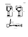
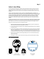
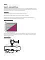
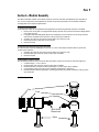
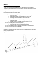
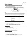
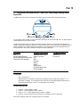
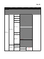
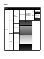
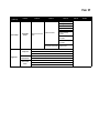
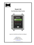
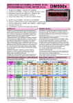
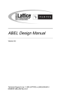
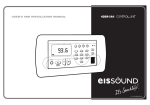
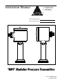
Instruction Manual Anderson Instrument Co. Inc. 156 Auriesville Road Fultonville, NY 12072 1-800-833-0081 Fax 518-922-8997 Instrument Model Number Instrument Serial Number "MPF" Modular Pressure Transmitter Form Number AIC2072 © 7/11 Revised: 8/15/13 Supersedes: 11/14/12 PAGE 3 Section 1 - Introduction 1.1 Specifications Table of Contents 4 4 Section 2 - Theory of Operation and Description Section 3 - Installation Section 4 - Sensor Wiring Section 5 - Instrument Wiring 6 6 7 8 Section 6 - Modular Assembly 9 5.1 LOOP POWER 6.1 Electronic puck replacement 6.2 Separation of measurement cell (stem) from enclosure 6.3 Reorientation of enclosure to stem 6.4 Remote Kit and MPFs equipped with remote configuration 8 9 9 9 10 Section 7 - Configuration 11 Section 8 - Calibration 17 Section 9 - Maintenance/Diagnostics Section 10 - HART Communicator Connection & DD (Device Descriptor) Menu Structure 22 24 Section 11 - Warranty and Return Statement 28 7.1 - Configuration (without display) - Native Units, Output, Range, Dampening 7.1.1 Display Mode: 4-20mA or Process Variable 7.1.2 Native Units: PSI or Bar 7.1.3 Output: 4mA – 20mA or 20mA – 4mA 7.1.4 Pressure Range 7.1.41 LRV: Lower range value 7.1.42 URV: Upper range value 7.1.5 Output Damping 7.1.6 Factory configuration reset 7.2 - Configuration (with display interface) - Native Units, Output, Range, Damping, Alarms, Display Units 7.2.1 Run Mode: 7.2.2 Native Units: PSI or Bar 7.2.3 Output: 4mA – 20mA or 20mA – 4mA 7.2.4 Pressure Range 7.2.41 LRV: Lower range value 7.2.42 URV: Upper range value 7.2.5 Output Damping 7.2.6 Setting Alarms – Alarms are visual indication only if MPF is not optioned with relays 7.2.7 Setting display process variable 7.2.8 Setting display process variable marquee time. 7.2.9 Factory configuration reset 8.1 CALIBRATION – Zero 8.2 CALIBRATION - Range 8.21 Custom calibration range – GAUGE STEM, 4 point 8.22 Custom calibration range – GAUGE STEM, 2 point 8.23 Custom calibration range – COMPOUND STEM, 4 point 8.24 Custom calibration range –COMPOUND STEM, 2 point 8.25 Custom calibration range – ABSOLUTE STEM, 4 point 8.26 Custom calibration range –ABSOLUTE STEM, 2 point 8.3 Calibration –Milliamp Meter 10.1 Attaching HART Communicator 10.2 HART DD Menu Structure 11 11 11 11 12 12 12 12 12 13 13 13 14 14 14 14 14 15 15 15 16 17 17 18 19 19 20 20 21 21 24 24 PAGE 4 Section 1 - Introduction 1.1 Specifications Performance Mechanical & Electrical: Calibrated Accuracy: ± 0.10% of calibrated range up to 5:1 turndown (± 0.15% if over 5:1 turndown) Repeatability: 0.05% as calibrated Long Term Stability: 0.2% URL for 2 years Process Temperature Effect: ± 0.1 psi/10°F (5.5°C) typical Ambient Temperature Effect: ± 0.1 psi/10°F (5.5°C) typical Over-Range Capability: 30/100/500 psi stem: 1.5x URL no effect on accuracy 2x URL to failure 1000 psi stem: 1.1x URL no effect on accuracy 1.25x URL to failure Response Time: <100 Milliseconds Sampling Rate: <50 Milliseconds Damping: Menu adjustable Range Turndown Capability: 10 to 1 turn down from URL Ranges, URL (PSI): 30,100,500,1K gauge and compound 30,100,500 absolute Ranges, URL (BAR): 2,7,35,70 gauge and compound 2,7,35 absolute ENVIRONMENTAL: Process Temperature Limits: 0 to 350°F (-18 to 177°C) with ambient temperatures to 140°F (60°C) and 0 to 330°F (0 to 71°C) with ambient temperatures to 160°F (71°C) Ambient Temperature Limits: 32 to 160°F (0 to 71°C) Enclosure Protection: NEMA 4X & IP66 IP69K(when equipped with QDR) Construction / Finish: Product Contact: 316L finished to a Min. Ra =25 microinches. Optional: Hastelloy® diaphragm Non-Product Contact Metal: 304 finished to a Min. Ra =32 microinches Non-Product Contact Plastic: polycarbonate threaded cap. Delrin atmospheric vent Wiring Connection: M16 x 1.5 threaded housing electrical entry Equipped with: Standard - replaceable M12 5 pin Eurofast QDR Optional - M16 Cord Grip, M16 x 1.5" NPTF adaptor Operational: Internal Fill: ETR (Extended Temperature Range) FDA approved mineral oil, Optional Neobee 20® Output: 2 wire user selectable 4-20 mA DC or 20-4 mA Optional - HART 7.0 digital communications protocol Internal Display: 4 digit LED nominally displays loop current. Process variable selectable - PSI or BAR. Display Interface: Optional; modular field replaceable. Millibar, Torr & Kg/cm2,PSI,BAR, kPA, In H2O, In Hg, mm H2O, mA Loop Resistance: 0-300 ohms at 24 VDC Electrical Connection: screw terminals with a conductor cross section range of 14-26 AWG Recommended Cable: Anderson shielded molded cordset, alternatively: 22-24 AWG, foil shielded, 0.17 - 0.26” Cable Sheath OD for use with cord grip or field wiring connector Electrical Protection: Voltage spike and reverse polarity Operating Voltage: 18-36 VDC (24 VDC Nominal regulated or unregulated) Zero Adjustment: one touch Re-Span: With switch through user interface & with or without a reference pressure source Electronics Puck: Modular, field replaceable Fitting & Sensor Stem: Modular, field replaceable Approvals and Documentation Sanitary: Authorized to display the 3-A Symbol, Third Party Verified, standard 74-03 Compliance: Compliant with the Pressure Equipment Directive relative to Sound Engineering Practices(PED) HART 7.0 Compatible CSA-B51-03 CRN# CSAOF9754.5R1 Warranty: 2 years PAGE 5 3.56 Figure 1 - Dimensional 3.55Drawings 3.6" (91mm) 3.6" (91mm) 6.6" (167mm) 6.59 6.6" (167mm) 6.59 Horizontal Orientation Vertical Orientation Cable lengths available in 5’, 10’ and 25’ 7.87" (200mm) Remote Version PAGE 6 Section 2 - Theory of Operation and Description The Anderson Modular Pressure Transmitter (MPF) may be utilized for applications in which a process variable of pressure must be converted to an electronic signal. This unit utilizes an internal pressure transducer to convert the process measurement into a corresponding mV signal. The mV signal then passes through custom linearization and conditioning circuitry. The resulting signal is an industry standard 4-20 mA. This mA signal is factory set over the specified range of the unit. From here the signal may be sent to an Anderson digital display, microprocessor based controller, chart recorder, or customer supplied instrumentation. An integral diagnostic interface provides menu feedback, visually displays diagnostic error codes and nominally measures and displays either the loop current or process variable in PSI or BAR. In addition, the MPF may be supplied with a modular display interface for readout directly at the process location. The MPF Transmitter has been specifically designed for use in Dairy, Food or Beverage applications where accurate and repeatable pressure measurement is required. The measurement cell is integral to a welded sanitary diaphragm seal that is available in a variety of industry standard fitting styles and sizes. The process pressure deflects the metal diaphragm, transmitting the pressure to a transducer cell. The output signal, which is proportional to the process pressure, is then measured and processed. Section 3 - Installation The physical installation is the most important concern with regards to promoting sensor reliability. Sensors must be installed in such a way that the housing and cable is not subject to physical abuse. In addition, moisture or moist air must not be allowed to enter the sensor housing or cable. NOTE: The installer assumes responsibility for preventing water or water-vapor from entering the sensor housing by proper installation of the cap and appropriate cable preparation. Units equipped with M12 Quick Disconnects are rated to NEMA 4X and IP69X. Cable gland equipped units are rated to NEMA 4X and IP66. To facilitate electrical connections, your new MPF transmitter may be supplied with a 5pin M12 quick disconnect receptacle, a M16 cable gland, or a ½” NPTF threaded adaptor. If mounted horizontally, the cable connection should point downward. Also, to prevent entry of excessive moisture, it is highly recommended that flexible conduits not be connected directly to the sensor. If conduit is to be run to the sensor, it is preferable that the watertight connector provided with each sensor not be removed from the sensor. Instead, run the flexible conduit as near to the sensor as possible and utilize a seal-tight connector at the end of the conduit. Allow a short amount of cable to run between the sensor and the flexible conduit. This isolates the sensor housing from the conduit system and any moisture it may contain. If the conduit is connected directly to the sensor, the chances are high that the sensor will eventually fail due to excessive water or water vapor entry into the housing. NOTE: It is recommended that a sensor "ZERO" be performed at time of installation. Refer to section 8.1, page 16 for information on this procedure. PAGE 7 Section 4 - Sensor Wiring For wet environments requiring IP67 or greater environmental protection Anderson strongly recommends using available Anderson shielded molded cord-sets utilizing 5 pin M12 eurofast design quick disconnect. Anderson supplied cable meets all requirements for shielding and compatibility with MPF quick disconnect receptacle. Anderson recommends a cable of 24 gauge, 4 conductor, shielded (Belden #9534) or equivalent. Four conductor cable is utilized because of its roundness, which provides a suitable seal when used with seal-tight connectors, strain reliefs and rubber grommets. Irregular shaped cable does not allow for a watertight seal. If utilizing customer supplied cable, select a round cable with 22-24 AWG wire and a shield. In order for the Anderson provided seal-tight connector to seal on the cable, the O.D. of the cable must be between 3/16" and 1/4". If smaller cable is utilized, a different neoprene bushing must be used (must be customer supplied). If an alternate seal-tight type connector is going to be used, be absolutely certain that the rubber bushing will adequately seal on the cable. Do not use a connector intended for power cable (large inside diameter) if the sensor cable is only 1/4". Be sure to use Teflon thread tape when attaching the new seal-tight connector. Wiring to the conduit housing sensors is accomplished as follows: 1. Remove the housing cap and lift out cover plate or display (optional) to expose the wiring terminal block. Exercise care when disconnecting ribbon connectors. 2. Insert the cable through the seal-tight connector, stripping back approximately 2 inches of sheathing to expose the wires. 3. Two wires will be utilized for connections at the transmitter end of the loop. Normal color codes being RED (Loop +) and BLACK (Loop -). Trim off all unused wires, including the bare shield ground wire. To prevent a GROUND LOOP condition, be sure the shield material and the shield ground wire do not touch the sensor housing. Use an insulator such as electrical tape or heat shrink tubing if necessary. 4. Strip the tips of the remaining wires back approximately 3/8 of an inch and twist strands (tinning is highly recommended). 5. Using Figure 2, make the proper connections to the wiring connector (located inside the housing) Figure 2 - Wiring Terminal Connections EX DOWN MENU 0% 50% 100% + LO O P _ UP SE NS OR E M16 Cable Gland 5pin M12 Quick Disconnect Receptacle 1/2” NPTF Thread Adaptor M Optional Display Interface PAGE 8 Section 5 - Instrument Wiring With the proper wiring connections made at the senor end of the loop, it is now time to make final connections at the instrument end of the loop. The MPF may feed instruments such as Anderson digital display, microprocessor based controllers, chart recorders, or customer supplied instrumentation. 5.1 LOOP POWER The Anderson MPF requires loop power for operation. Ratings are as follows: MPF Transmitter: 18-36 VDC (Absolute), 24 VDC Nominal, regulated or unregulated As inherent resistance associated with cable length and signal receiver input may affect operation of the transmitter, Figure 3 shows some guidelines for loop power required. FIGURE 3 - Loop Power Guidelines 1000 800 700 600 500 Series2 400 300 200 100 36 34 32 30 28 26 24 22 20 0 18 Total Loop Resistance - Ohms 900 Loop Power Supply Voltage - VDC Please consult the Installation/Service Manual that was provided with your receiver for specific wiring instruction. Most Anderson receiver (displays, chart recorders, etc.) are capable of supplying loop power. Typical wiring would be as follows: FIGURE 4 - Sensor Wiring TOTAL LOOP RESISTANCE OPTIONAL LOOP + RED(+) LOOP BLACK(-) A AMMETER (4-20 mA DC) + POWER SUPPLY PER SPECS INPUT _ _ + SIGNAL RECEIVER SHIELD GROUND (ONE POINT ONLY) PAGE 9 Section 6 - Modular Assembly The MPF transmitter consists of two distinct sections, enclosure and stem that individually are comprised of one or more components. Field replacement of these components is possible to accommodate orientation reconfiguration and component replacement. 6.1 Electronic puck replacement Puck replacement may be accomplished at the application site assuming sufficient clearance is available. 1. Remove wire cover plate or if equipped with display squeeze clip connector and remove display ribbon from socket on puck. 2. If equipped with M12 QDR (quick disconnect receptacle) remove conductors from wiring connector and unscrew receptacle from enclosure. Factory torque spec is 20ft-lbs. 3. Squeeze clip connector and remove sensor ribbon from socket on puck 4. Unscrew ground lug, slide puck out of enclosure 5. Reverse to install 6.2 Separation of measurement cell (stem) from enclosure This proceed will require immobilizing the enclosure. If a vice is used steps should be taken to protect the surface of the enclosure 1. Squeeze clip connector and remove sensor ribbon from socket on puck 2. Unscrew stem from enclosure. Factory torque spec is 20ft-lbs. 3. Reverse to install 6.3 Reorientation of enclosure to stem The threaded penetrations of the enclosure allow orientation in either a horizontal or vertical arrangement. 1. Complete steps 1 - 3 of 6.1 above 2. Unscrew stem from enclosure. Factory torque spec is 20ft-lbs 3. Reassemble stem to desired enclosure penetration. Factory torque spec is 20ft-lbs 4. Connect ribbon cable connector to puck receptacle located next to ground lug. 5. Reassemble M12 QDR (if equipped) to remaining penetration and install conductors. Factory torque spec is 20ft-lbs FIGURE 5 - Exploded View Cap Puck Housing M12 Quick Disconnect Stem PAGE 10 6.4 Remote Kit and MPFs equipped with remote configuration The MPF series may be configured or retrofitted with remote cabling allowing the housing and display (if equipped) to be mounted up to 25 feet from the process connection. The remote cabling preserves the modular design and may be removed or added from the MPF at the user’s discretion. Adding the Remote kit. Refer to Figure 6. Note: all threaded connections to be torqued to 20ft-lbs 1. Separate the measurement cell (stem) from enclosure a. Remove wire cover plate or if equipped with Display Interface squeeze clip connector and remove display ribbon b. Squeeze clip connector and remove sensor ribbon from socket on puck c. Unscrew stem from enclosure. Utilize care extracting ribbon cable. 2. Attach remote kit cabling to measurement cell stem a. Route stem ribbon cable through kit stem adaptor. Screw on adaptor b. Connect ribbon cable connector to cable kit receptacle and carefully fold excess ribbon cable into stem adaptor c. Insert cable kit fitting into stem adaptor. Secure by threading on union nut 3. Attach remote QDR adaptor to desired enclosure opening a. Carefully insert ribbon cable through enclosure opening b. Screw remote QDR adaptor into place c. Connect ribbon cable connector into sensor receptacle on puck 4. Attach pipe mount adaptor to remote QDR adaptor and secure with nut. Position as required. 5. Attach remote kit M12 plug to remote QDR adaptor Reverse to un-install. WARNING – To avoid possible ribbon cable damage, remove union nut and unplug ribbon from socket before removing stem adaptor from stem. M R N ut ut N ni on U tR Ki le C ab Ad m te Ki tS ea su re m en tC el ap to r l(S te ec ep m ) ta cl em e ot e Q D ur os cl En R Ad ap to r e Figure 6 - Remote View PAGE 11 Section 7 - Configuration 7.1 - Configuration (without display) - Native Units, Output, Range, Dampening (See 7.2 for configuration with display interface) The MPF’s menu functions are accessed via the toggle switches on either side of the interface display U UP EX E D DOWN MENU M “U” up & “D” down are toggle pressed on the left switch, “E” execute & “M” menu are toggle pressed on the right switch All instructions assume start from “RUN” mode which is default at power on and milliamp output displayed. If multiple configuration changes are desired it is not necessary to exit to “RUN” mode before configuring the next desired operation. Once desired operation configuration is accomplished pressing “M” repeatedly will scroll through operations. Run mode is achieved when milliamp output is displayed. RUN Mode SENSOR CONFIG Mode Zero 4-20mA/Process Variable PSIG / BAR 4-20mA / 20-4mA LRV URV Damping Factory Restore Calibration Mode 2 Point Cal 4 Point Cal 7.1.1 Display Mode: 4-20mA or Process Variable 1. 2. 3. 4. Press “M” - Sensor displays “COnF” Press “U” & “E” simultaneously for 2 seconds - sensor displays “CvAL” or “PvAL” Press “U” or “D” - Sensor display toggles between “CvAL” or “PvAL” Press “M” to proceed to next operation or if no other operation is to be accessed exit to “RUN” 7.1.2 Native Units: PSI or Bar 1. 2. 3. 4. Press “M” – Sensor displays “COnF” Press “E” – Sensor displays “PSI” or “BAR” Press “U” or “D” – Sensor toggles between “PSI” or “BAR” Press “M” to proceed to the next operation Note: When changing native units configuring range is now required 7.1.3 Output: 4mA – 20mA or 20mA – 4mA 1. 2. 3. 4. 5. Press “M” – Sensor displays “COnF” Press “E” – Sensor displays “PSI” or “BAR” Press “M” – Sensor displays “4-20” or “20-4” Press “U” or “D” – Sensor toggles between “4-20” or “20-4” If no other operation is to be accessed exit to “RUN” mode via pressing “M” repeatedly PAGE 12 7.1.4 Pressure Range 7.1.41 LRV: Lower range value Sensors equipped with ”Compound” style measurement cells (stem) may configure the LRV. “Gauge” and “Absolute” stems are predefined as 0 and are not reconfigurable 1. 2. 3. 4. 5. 6. Press “M” – Sensor displays “COnF” Press “E” – Sensor displays “PSI” or “BAR” Press “M” – Sensor displays “4-20” or “20-4” Press “M” – Sensor displays “LRV” Press “E” – Sensor displays present LRV value – Example: “0” Press “U” or “D” to set desired LRV value– Sensor display increases or decreases accordingly Note: continue to URV 7.1.42 URV: Upper range value Note: starting from 7.31 above 7. Press “M” – Sensor displays “URV” 8. Press “E” – Sensor displays present URV value – Example: “50” 9. Press ”U” or “D” to set desired URV value – Sensor display increases or decreases accordingly 10. Press “E” to store displayed value – Sensor displays “URV” 11. If no other operation is to be accessed exit to “RUN” mode via pressing “M” repeatedly 7.1.5 Output Damping 1. 2. 3. 4. 5. 6. 7. 8. 9. 10. Press “M” – Sensor displays “COnF” Press “E” – Sensor displays “PSI” or “BAR” Press “M” – Sensor displays “4-20” or “20-4” Press “M” – Sensor displays “LRV” Press “M” – Sensor displays “URV” Press “M” – Sensor displays “dMPg” Press “E” – Sensor displays current damping value from 0 - 10 Press “U” or “D” to display desired damping value– Sensor display increases or decreases accordingly Press “E” to store displayed value – Sensor displays “dMPg” If no other operation is to be accessed exit to “RUN” mode via pressing “M” repeatedly until milliamp output is displayed 7.1.6 Factory configuration reset Perform if a return to the original factory configuration is desired 1. 2. 3. 4. 5. 6. 7. 8. 9. 10. 11. Press “M” – Sensor displays “COnF” Press “E” – Sensor displays “PSI” or “BAR” Press “M” – Sensor displays “4-20” or “20-4” Press “M” – Sensor displays “LRV” Press “M” – Sensor displays “URV” Press “M” – Sensor displays “dMPg” Press “M” – Sensor display “FrES” Press “E” – Sensor display “nO” Press “U” or “D” to display “YES” Press “E” – Sensor display “FrES” Exit to “RUN” mode via pressing “M” repeatedly until milliamp output is displayed PAGE 13 7.2 - Configuration (with display interface) - Native Units, Output, Range, Damping, Alarms, Display Units The MPF’s menu functions are accessed via the arrow buttons on either side of the interface display 0% Down Execute 50% 100% E M Up Menu “U” up & “D”are button presses on the right and left of the display. “E” execute and “M” menu are button presses located between the up and down arrows. All instructions assume start from “RUN” mode which is default at power on and process value displayed. If multiple configuration changes are desired it is not necessary to exit to “RUN” mode before configuring the next desired operation. Once desired operation configuration is accomplished pressing “M” repeatedly will scroll through operations. Run mode is achieved when process value is displayed. RUN Mode SENSOR CONFIG Mode Zero PSIG/BAR (native units) Adjust Display Decimal 4-20mA / 20-4mA Momentarily Display mA Output LRV Descriptive Error Message URV Damping Alarm1 Alarm2 Display Units Unit Description Scroll Factory Restore Calibration Mode 2 Point Cal 4 Point Cal 7.2.1 Run Mode: Zero - see section 8.1 Display Decimal - the number of decimal places displayed may be adjusted by pressing ñ or ò Momentary mA display - the measured process value may be monetarily displayed by pressing “E” Descriptive Error Message - press ñ for a descriptive error message. 7.2.2 Native Units: PSI or Bar 1. 2. 3. 4. Press “M” – Sensor displays “CONF” Press “E” – Sensor displays “PSIG” or “BARG” Press “U” or “D” – Sensor toggles between “PSIG” or “BARG” Press “M” once to proceed to the next operation or repeatedly to return to Run Mode Note: When changing native units configuring range is now required PAGE 14 7.2.3 Output: 4mA – 20mA or 20mA – 4mA 1. 2. 3. 4. 5. Press “M” – Sensor displays “CONF” Press “E” – Sensor displays “PSIG” or “BARG” Press “M” – Sensor displays “4-20” or “20-4” Press “U” or “D” – Sensor toggles between “4-20” or “20-4” If no other operation is to be accessed exit to “RUN” mode via pressing “M” repeatedly 7.2.4 Pressure Range 7.2.41 LRV: Lower range value Sensors equipped with “Compound” style measurement cells (stem) may configure the LRV. “Gauge” and “Absolute” stems are predefined as 0 and are not reconfigurable 1. 2. 3. 4. 5. 6. Press “M” – Sensor displays “CONF” Press “E” – Sensor displays “PSIG” or “BARG” Press “M” – Sensor displays “4-20” or “20-4” Press “M” – Sensor displays “LRV” Press “E” – Sensor displays present LRV value – Example: “0” Press “U” or “D” to set desired LRV value– Sensor display increases or decreases accordingly Note: continue to URV 7.2.42 URV: Upper range value Note: starting from 7.2.41 above 7. Press “M” – Sensor displays “URV” 8. Press “E” – Sensor displays present URV value – Example: “50” 9. Press “U” or “D” to set desired URV value – Sensor display increases or decreases accordingly 10. Press “E” to store displayed value – Sensor displays “URV” 11. If no other operation is to be accessed exit to “RUN” mode via pressing “M” repeatedly 7.2.5 Output Damping 1. 2. 3. 4. 5. 6. 7. 8. 9. 10. Press “M” – Sensor displays “CONF” Press “E” – Sensor displays “PSIG” or “BARG” Press “M” – Sensor displays “4-20” or “20-4” Press “M” – Sensor displays “LRV” Press “M” – Sensor displays “URV” Press “M” – Sensor displays “DAMP” Press “E” – Sensor displays current damping value from 0 - 10 Press “U” or “D” to display desired damping value– Sensor display increases or decreases accordingly Press “E” to store displayed value – Sensor displays “DAMP” If no other operation is to be accessed exit to “RUN” mode via pressing “M” repeatedly until process value is displayed PAGE 15 7.2.6 Setting Alarms – Alarms are visual indication only if MPF is not optioned with relays 1. 2. 3. 4. 5. 6. 7. 8. 9. 10. 11. 12. 13. 14. 15. 16. 17. 18. 19. 20. Press “M” – Sensor displays “CONF” Press “E” – Sensor displays “PSIG” or “BARG” Press “M” – Sensor displays “4-20” or “20-4” Press “M” – Sensor displays “LRV” Press “M” – Sensor displays “URV” Press “M” – Sensor displays “DAMP” Press “M” – Sensor displays “ALRM1” Press “E” – Sensor displays “OFF” or “ON” Press “U” or “D” – Sensor toggles between “ON” or “OFF” set to “ON” Press “E” – Sensor displays “High” or “LOW” Press “U” or “D” – Sensor toggles between “HIGH” or “LOW” Choose either active high or active low Press “E” – Sensor displays “SETPT” Press “E” – Sensor displays set point pressure. Press “U” or “D” repeatedly to select alarm1 pressure Press “E” – Sensor displays “HYST” (allows hysteresis or dead band) Press “E” – Sensor displays “0” or “1” (turns on dead band preset at 1% of set point) Press “U” or “D” – Sensor toggles between “0” or “1” Press “E” – Sensor displays “ALRM1” Press “M” – Sensor displays “ALRM2” Repeat from instruction 8 to set alarm 2 if desired otherwise press “M” to proceed to next operation or repeatedly to exit to “run” mode 7.2.7 Setting display process variable The following Engineering units may be selected: PSI, BAR, kPa, In H2O, In Hg, mm H20, mm Hg, or Milliamp output 1. 2. 3. 4. 5. 6. 7. 8. 9. 10. 11. Press “M” – Sensor displays “CONF” Press “E” – Sensor displays “PSIG” or “BARG” Press “M” – Sensor displays “4-20” or “20-4” Press “M” – Sensor displays “LRV” Press “M” – Sensor displays “URV” Press “M” – Sensor displays “DAMP” Press “M” – Sensor displays “ALRM1” Press “M” – Sensor displays “ALRM2” Press “M” – Sensor displays currently set engineering unit Press “U” or “D” repeatedly to select the desired engineering unit Press “M” to proceed to next operation or repeatedly to exit to “run” mode 7.2.8 Setting display process variable marquee time. The display may be set to repeatedly scroll the Engineering unit selected in a marquee style Note: There is no marquee function if milliamp is selected. 1. 2. 3. 4. 5. 6. 7. 8. 9. 10. 11. 12. 13. Press “M” – Sensor displays “CONF” Press “E” – Sensor displays “PSIG” or “BARG” Press “M” – Sensor displays “4-20” or “20-4” Press “M” – Sensor displays “LRV” Press “M” – Sensor displays “URV” Press “M” – Sensor displays “DAMP” Press “M” – Sensor displays “ALRM1” Press “M” – Sensor displays “ALRM2” Press “M” – Sensor displays “UDISP” Press “E” – Sensor displays “OFF” or the current marquee scroll interval Press “U” or “D” repeatedly to select the desired scroll interval Press “E” – to store, sensor displays “UDISP” Press “M” to proceed to next operation or If no other operation is to be accessed exit to “RUN” mode via pressing “M” repeatedly until process variable is displayed PAGE 16 7.2.9 Factory configuration reset Perform if a return to the original factory configuration is desired 1. 2. 3. 4. 5. 6. 7. 8. 9. 10. 11. Press “M” – Sensor displays “CONF” Press “E” – Sensor displays “PSIG” or “BARG” Press “M” – Sensor displays “4-20” or “20-4” Press “M” – Sensor displays “LRV” Press “M” – Sensor displays “URV” Press “M” – Sensor displays “DAMP” Press “M” – Sensor display “FAC” Press “E” – Sensor display “nO” Press “U” or “D” to display “YES” Press “E” – Sensor display “FAC” Exit to “RUN” mode via pressing “M” repeatedly until process value is displayed PAGE 17 Section 8 - Calibration The MPF is calibrated at the factory to meet the specified accuracy for any allowable range that may be configured. As general maintenance to the unit, a zero check is recommended at approximately 12 month intervals. Over time errors may be accumulated due to the impact of environment and operation. If you feel that the output of the MPF transmitter is not correct, calibration of the unit may be required. Accumulated offset errors have the greatest impact to accuracy over time. These may easily be addressed in the “field” via the “one touch Zero” function in section 8.1. Further calibration to address possible errors in the range may be addressed in the field but will require analytical caliber equipment to provide accurate pressure standards. The MPF may also be returned to Anderson for a full factory recalibration. 8.2 illustrates the procedures for custom range calibration of the transmitter. 8.1 CALIBRATION – Zero NOTE – For ABSOLUTE stems zero calibration is disabled as zeroing is not possible in atmospheric conditions. All instructions assume starting from “RUN” mode which is default at power on and process value displayed. Zeroing the sensor provides the best accuracy when clamped into the application therefore negates possible positioning and clamping errors. Be sure sensor is exposed to zero psig when performing this function. Units Without Display: 1. Press both “D” and “M” simultaneously for approximately 5 seconds – Sensor displays 4.00 milliamp for gauge, for compound sensor displays appropriate output for set range. Units with Display Interface: 1. Press both ò and “M” simultaneously for approximately 5 seconds. 8.2 CALIBRATION - Range Field calibration of the MPF results in a “custom calibration” range. This may be desired as it provides (in 4 point calibration mode) the best possible accuracy for a given specific range. Once this procedure is completed care should be taken not to perform any subsequent “configuration” range changes as this will result in returning to the original factory calibration data. When performing this calibration the range desired must be first set in the “configuration” mode. Refer to 7.1.4 for integral display or 7.2.4 for display interface to set this range. Equipment required: Pressure suitable standard that can achieve URV, Accurate reference gauge, DC Milliamp Meter (accurate to +/- .005 mA) The MPF accommodates both 2 point and 4 point calibrations. 4 point calibrations yield the most accurate results and are therefore preferred. If your unit is calibrated at a “COMPOUND” range, you will not see 4.00 mA at atmospheric zero. As reference, you may use the following chart to determine if your unit may require calibration (most common ranges are shown). Sensor Range Sensor Reads at Atmospheric Zero 0-psig - Positive Pressure 4.00 mA 0-psig - 30" Hg 4.00 mA 30" Hg - 15 psig 11.92 mA 30" Hg - 30 psig 9.26 mA 30" Hg - 60 psig 7.15 mA 30" Hg - 100 psig 6.05 mA PAGE 18 The output of a properly calibrated transmitter may be calculated by using the following formula: mA Output = [ 16 x [ (KNOWN VALUE - LOW END OF RANGE TRANSMITTER SPAN ] ] +4 NOTE: For pressure transmitters with compound ranges, the ranges must first be converted to all one type unit of measure. For example, a 30" Hg/0/35 psig unit maybe considered to have a range of -14.7 psig-0-35 psig and a span of 49.7 psig (2.036" Hg = 1 psi). Be careful not to lose the (-) sign while performing the calculation of the proper reading. If your unit is calibrated at a “ABSOLUTE” range, you will not see 4.00 mA at atmospheric zero. Calibration requires an analytical quality pressure source and reference gauge NOTE: The transmitter should be wired in a complete loop at this point, or on a test bench and configured per the diagram shown in Figure 4, page 8. 8.21 Custom calibration range – GAUGE STEM, 4 point For units with Display Interface: ò= D ñ=U 1. Clamp sensor into calibration fitting and expose the transmitter to a known zero reference point. 2. Set meter to DC mA and connect meter in series with loop + . 3. Press “M” – Sensor displays “COnF” 4. Press “M” – Sensor displays “CAL” 5. Press “E” – Sensor displays “CCAL” 6. Press “E” – Sensor displays “2PtS” 7. Press “U” or “D” to set 4 point calibration – Sensor displays “4PtS” 8. Press “E” holding for approximately 2 seconds – Sensor displays “ArEF” (“ATM” with Display Interface) 9. Expose sensor to atmospheric pressure 10. Press “E” – Sensor will store the atmospheric reference and displays “LrV” 11. Press “E” – Sensor will store LRV reference and displays “Pt2” 12. Press “E” – Sensor display will prompt the desired pressure standard. Press òorñto adjust. 13. Expose sensor to requested pressure 14. Press “E” – Sensor displays “Pt3” 15. Press “E” – Sensor display will prompt the desired pressure standard. Press òorñto adjust. 16. Expose sensor to requested pressure 17. Press “E” – Sensor displays “UrV” 18. Press “E” – Sensor display will prompt the desired pressure standard. 19. Expose sensor to requested pressure 20. Press “E” – Sensor displays “CCAL” Exit to “RUN” mode via pressing “M” repeatedly until process value is displayed PAGE 19 8.22 Custom calibration range – GAUGE STEM, 2 point 1. Clamp sensor into calibration fitting and expose the transmitter to a known zero reference point. 2. Set meter to DC mA and connect meter in series with loop + . 3. Press “M” – Sensor displays “COnF” 4. Press “M” – Sensor displays “CAL” 5. Press “E” – Sensor displays “CCAL” 6. Press “E” – Sensor displays “2PtS” 7. Press “U” or “D” to set 2 point calibration sensor displays “2PtS” 8. Press “E” holding for approximately 2 seconds – Sensor displays “ArEF” (“ATM” with Display Interface) 9. Expose sensor to atmospheric pressure 10. Press “E” – Sensor displays “LrV” 11. Press “E” – Sensor display will prompt the desired pressure standard. 12. Expose sensor to requested pressure 13. Press “E” – Sensor displays “UrV” 14. Press “E” – Sensor display will prompt the desired pressure standard. 15. Expose sensor to requested pressure 16. Press “E” – Sensor displays “CCAL” Exit to “RUN” mode via pressing “M” repeatedly until process value is displayed 8.23 Custom calibration range – COMPOUND STEM, 4 point NOTE: For pressure transmitters with compound ranges, the ranges must first be converted to all one type unit of measure. For example, a 30" Hg - 0-30 psig unit may be considered to have a range of -14.7 psig - 0-30 psig and a span of 44.7 psig (2.036" Hg = 1 psi). Be careful not to lose the (-) sign while performing the calculation of the proper reading. 1. 2. 3. 4. 5. 6. 7. 8. 9. 10. 11. 12. 13. 14. 15. 16. 17. 18. 19. 20. 21. 22. 23. Clamp sensor into calibration fitting and expose the transmitter to a known zero reference point. Set meter to DC mA and connect meter in series with loop + . Press “M” – Sensor displays “COnF” Press “M” – Sensor displays “CAL” Press “E” – Sensor displays “CCAL” Press “E” – Sensor displays “2PtS” Press “U” or “D” to set 4 point calibration – Sensor displays “4PtS” Press “E” holding for approximately 2 seconds – Sensor displays “ArEF” (“ATM” with Display Interface) Expose sensor to atmospheric pressure Press “E” – Sensor will store the atmospheric reference and displays “LrV” Press “E” – Sensor display will prompt the desired pressure standard. Press òorñ to adjust. Expose sensor to requested pressure Press “E” – Sensor displays “Pt2” Press “E” – Sensor display will prompt the desired pressure standard. Press òorñ to adjust. Expose sensor to requested pressure Press “E” – Sensor displays “Pt3” Press “E” – Sensor display will prompt the desired pressure standard. Press òorñ to adjust. Expose sensor to requested pressure Press “E” – Sensor displays “UrV” Press “E” – Sensor display will prompt the desired pressure standard. Expose sensor to requested pressure Press “E” – Sensor displays “CCAL” Exit to “RUN” mode via pressing “M” repeatedly until process value is displayed PAGE 20 8.24 Custom calibration range –COMPOUND STEM, 2 point 1. 2. 3. 4. 5. 6. 7. 8. 9. 10. 11. 12. 13. 14. 15. 16. 17. Clamp sensor into calibration fitting and expose the transmitter to a known zero reference point. Set meter to DC mA and connect meter in series with loop + . Press “M” – Sensor displays “COnF” Press “M” – Sensor displays “CAL” Press “E” – Sensor displays “CCAL” Press “E” – Sensor displays “2PtS” Press “U” or “D” to set 2 point calibration sensor displays “2PtS” Press “E” holding for approximately 2 seconds – Sensor displays “ArEF”(“ATM” with Display Interface) Expose sensor to atmospheric pressure Press “E” – Sensor will store the atmospheric reference and displays “LrV” Press “E” – Sensor display will prompt the desired pressure standard. Press òorñ to adjust. Expose sensor to requested pressure Press “E” – Sensor displays “UrV” Press “E” – Sensor display will prompt the desired pressure standard. Expose sensor to requested pressure Press “E” – Sensor displays “CCAL” Exit to “RUN” mode via pressing “M” repeatedly until process value is displayed 8.25 Custom calibration range – ABSOLUTE STEM, 4 point 1. Clamp sensor into calibration fitting and expose the transmitter to a known zero reference point. 2. Set meter to DC mA and connect meter in series with loop + . 3. Press “M” – Sensor displays “COnF” 4. Press “M” – Sensor displays “CAL” 5. Press “E” – Sensor displays “CCAL” 6. Press “E” – Sensor displays “2PtS” 7. Press “U” or “D” to set 4 point calibration – Sensor displays “4PtS” 8. Press “E” – holding for approximately 2 seconds – Sensor displays “LrV” 9. Press “E” – Sensor displays “VAC”. Press òorñ to adjust. 10. Expose sensor to requested pressure 11. Press “E” – Sensor displays “Pt2” 12. Press “E” – Sensor display will prompt the desired pressure standard. Press òorñ to adjust. 13. Expose sensor to requested pressure 14. Press “E” – Sensor displays “Pt3” 15. Press “E” – Sensor display will prompt the desired pressure standard. Press òorñ to adjust. 16. Expose sensor to requested pressure 17. Press “E” – Sensor displays “UrV” 18. Press “E” – Sensor display will prompt the desired pressure standard. 19. Expose sensor to requested pressure 20. Press “E” – Sensor displays “CCAL” Exit to “RUN” mode via pressing “M” repeatedly until milliamp output is displayed PAGE 21 8.26 Custom calibration range –ABSOLUTE STEM, 2 point 1. Clamp sensor into calibration fitting and expose the transmitter to a known zero reference point. 2. Set meter to DC mA and connect meter in series with loop + . 3. Press “M” – Sensor displays “COnF” 4. Press “M” – Sensor displays “CAL” 5. Press “E” – Sensor displays “CCAL” 6. Press “E” – Sensor displays “2PtS” 7. Press “U” or “D” to set 2 point calibration sensor displays “2PtS” 8. Press “E” holding for approximately 2 seconds – Sensor displays “LrV” 9. Press “E” – Sensor displays “VAC”. Press òorñ to adjust. 10. Expose sensor to requested pressure 11. Press “E” – Sensor displays “UrV” 12. Press “E” – Sensor display will prompt the desired pressure standard. 13. Expose sensor to requested pressure 14. Press “E” – Sensor displays “CCAL” Exit to “RUN” mode via pressing “M” repeatedly until milliamp output is displayed 8.3 Calibration –Milliamp Meter The MPF contains circuitry to measure the loop current. This meter may be calibrates to match a users external reference. 1. Press “M” – Sensor displays “COnF” 2. Press “M” – Sensor displays “CAL” 3. Press “E” – Sensor displays “CCAL” 4. Press “M” – Sensor displays “MCAL” 5. Press “E” – Sensor displays “04 mA” 6. Press “U” or “D” to match external reference to 4 mA. 7. Press “E” – Sensor displays “20 mA” 8. Press “U” or “D” to match external reference to 20 mA. 9. Press “E” – to store values - sensor displays “MCAL” Exit to “RUN” mode via pressing “M” repeatedly until process value is displayed PAGE 22 Section 9 - Maintenance/Diagnostics Anderson electronic sensors require very little maintenance, if any. We suggest that the sensor be inspected at 6 month intervals to ensure that they are not being subjected to physically abuse, moisture entering the housing, and that the wiring is sound. The MPF is equipped with diagnostic routines that monitor the sensor’s function. Should an error occur the diagnostic display will flash an error code and the output will be limited to 3.8 mA or less. Errors may be caused by a number of reasons ranging from failed electronic components to user configuration errors. The code appendix below indicates possible codes with actions that should be taken to correct the problem. Error codes may be cleared to facilitate subsequent menu changes, however the output will remain at 3.8 mA or less until error is addressed and the unit repowered. Always record the error code before attempting to clear it. The display code may be erased as follows: 1. From “RUN” Mode Press “D” or ò and hold for several seconds. Some error codes will not erase until problem is resolved – Sensor displays current process value. 2. Power cycle by removing power for 10 seconds then reattach power. 3. For units equipped with optional display interface press ñfor a descriptive error message. PAGE 23 Error Code Category Customer Action No visible code, 3.8 mA output Communication e700 Internal System Failure Reset Error and power cycle and if error is persistent replace puck e701 Internal System Failure Reset Error and power cycle and if error is persistent replace puck e702 Internal System Failure Reset Error and power cycle and if error is persistent replace puck e500 Communication e501 Stem Data Corruption Replace Stem e502 Stem Data Corruption Replace Stem e503 Stem Data Corruption Replace Stem e504 Stem Data Corruption Replace Stem e505 Insufficient loop voltage e300 Stem Data Corruption Replace Stem e301 Stem Data Corruption Replace Stem e302 Stem Data Corruption Replace Stem e304 Stem Data Corruption Replace Stem e405 Puck Data Corruption Replace Puck e406 Puck Data Corruption Replace Puck e407 Puck Data Corruption Replace Puck e600 Puck Data Corruption Replace Puck e602 Stem Configuration Error Reset Error and power cycle and if error is persistent replace Stem e603 Stem Configuration Error Reset Error and power cycle and if error is persistent replace Stem e100 Incompatible Range 1) Reconfigure puck to a range compatible with the stem 2) power cycle 3) Reset Error e101 Incompatible Range/ range changed 1) Reconfigure puck to a range compatible with the stem 2) power cycle 3) Reset Error e200 Installation Fault Power Cycle e201 Communication Power Cycle e202 Communication Power Cycle e203 Communication Power Cycle e204 Data Corruption Factory restore OVER Warning Check Stem ribbon cable connection to puck, power cycle Check Stem ribbon cable connection to puck, power cycle Check if loop voltage is at least 18V, provide correct voltage then power cycle Check Process - URV exceeded, cycle power to reset Feel free to contact Anderson Technical Services Department at 1-800-833-0081 for further assistance with troubleshooting. PAGE 24 Section 10 - HART Communicator Connection & DD (Device Descriptor) Menu Structure MPF transmitters can be equipped with an optional HART output protocol and may be addressed via an external HART modem or alternatively via a portable HART communicator (HHT) compatible with HART 7.0. 10.1 Attaching HART Communicator 1. Power the MPF Transmitter. The signal loop must have at least 250ohms resistance for HHT function 2. Connect the HHT across the transmitter terminals or the resister loop 3. Turn on the HHT, wait until communications are established and the Home Menu is displayed 10.2 HART DD Menu Structure All MPF functions as well as standard HART setup detail may be addressed via the HART DD menu. See following Menu DD for specific required paths. PAGE 25 Home Screen (Level 1) Loop Current PV Value URV LRV Sensor Type Level 2 Level 3 Loop Direction LRV URV Damping Display Units Configuration Device Setup Native Units Alarm 1 (or) Alarm 2 Factory Restore Meter Calibration Calibration Sensor Calibration Level 4 Level 5 4mA to 20mA 20mA to 4mA LRV Change Range URV Change Range Damping Value Change Damping inH2O inHg mmH2O mmHg PSI BAR mBAR kPa 2 Kg/cm TORR PSI BAR Energized Active High Out Of SPAN Enabled Set Point Hysteresis Turn On/Off Change Type Change SP Change Hysteresis Yes / No Set 4mA Set 20mA Two Point Calibration Four Point Calibration Sensor Type PV URV PV LRV Calibration Level 6 Level 7 PAGE 26 Home Screen (Level 1) Level 2 Level 3 Level 4 Level 5 Level 6 Burst Mode Level 7 On / Off Choose Command Burst Configuration HART Configuration HART Setup HART Information Device Setup HART Output HART Review Review Device Information Burst Message 1 Burst Message 2 Burst Message 3 Burst Option Update Period Maximum Update Period Trigger Condition Device Variable Classification Burst units Trigger Level Number of Response Preambles Loop Current Mode Enable / Disable Polling Address Model Manufacturer Device ID HART Universal Revision Descriptor Message Date Tag Long Tag Final Assembly Number PV Pressure Value Manufacturer ID Universal Rev Field Device Rev Software rev Hardware Rev Tag Descriptor Message Configuration Change Counter PV Native Units PV Display Units PV LRV PV URV PV Pressure USL PV Pressure LSL PV Damping Firmware Rev Serial Number PAGE 27 Home Screen (Level 1) Device Setup Level 2 Extended Setup Level 3 Clone Instrument Info Level 4 HART Variables Level 5 Descriptor Message Date Tag Long Tag Final Assembly Number Number of Request Preamble Number of Response Preamble Instrument Parameter Display Units Loop Test Diagnostics Error Information One Touch Zero Choose 4 mA Choose 20 mA Choose other mA value Error code with Description Reset Error Codes PV Value Loop Value Zero Trim Level 6 Level 7 PAGE 28 Section 11 - Warranty and Return Statement These products are sold by The Anderson Instrument Company (Anderson) under the warranties set forth in the following paragraphs. Such warranties are extended only with respect to a purchase of these products, as new merchandise, directly from Anderson or from an Anderson distributor, representative or reseller, and are extended only to the first buyer thereof who purchases them other than for the purpose of resale. Warranty These products are warranted to be free from functional defects in materials and workmanship at the time the products leave the Anderson factory and to conform at that time to the specifications set forth in the relevant Anderson instruction manual or manuals, sheet or sheets, for such products for a period of two years. THERE ARE NO EXPRESSED OR IMPLIED WARRANTIES WHICH EXTEND BEYOND THE WARRANTIES HEREIN AND ABOVE SET FORTH. ANDERSON MAKES NO WARRANTY OF MERCHANTABILITY OR FITNESS FOR A PARTICULAR PURPOSE WITH RESPECT TO THE PRODUCTS. Limitations Anderson shall not be liable for any incidental damages, consequential damages, special damages, or any other damages, costs or expenses excepting only the cost or expense of repair or replacement as described above. Products must be installed and maintained in accordance with Anderson instructions. Users are responsible for the suitability of the products to their application. There is no warranty against damage resulting from corrosion, misapplication, improper specifications or other operating condition beyond our control. Claims against carriers for damage in transit must be filed by the buyer. This warranty is void if the purchaser uses non-factory approved replacement parts and supplies or if the purchaser attempts to repair the product themselves or through a third party without Anderson authorization. Returns Anderson’s sole and exclusive obligation and buyer’s sole and exclusive remedy under the above warranty is limited to repairing or replacing (at Anderson’s option), free of charge, the products which are reported in writing to Anderson at its main office indicated below. Anderson is to be advised of return requests during normal business hours and such returns are to include a statement of the observed deficiency. The buyer shall pre-pay shipping charges for products returned and Anderson or its representative shall pay for the return of the products to the buyer. Approved returns should be sent to: ANDERSON INSTRUMENT COMPANY INC. 156 AURIESVILLE ROAD FULTONVILLE, NY 12072 USA ATT: REPAIR DEPARTMENT ANDERSON INSTRUMENT CO., INC • 156 AURIESVILLE RD. • FULTONVILLE, NY 12072 • USA • 800-833-0081 • FAX 518-922-8997 ANDERSON INSTRUMENT CO. LP • 400 BRITANNIA RD. EAST, UNIT 1 • MISSISSAUGA, ONTARIO L4Z 1X9 • CANADA • 905-603-4358 • FAX 905-568-1652 NEGELE MESSTECHNIK GmbH (A Division of Anderson) • Raiffeisenweg 7 • D-87743 Egg a. d. Günz • GERMANY • +49 (0) 8333/9204-0 • FAX +49 (0) 8333/9204-49 www.andinst.com