1
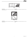
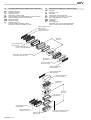
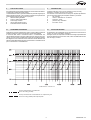
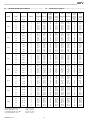
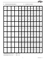
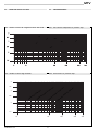
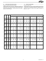
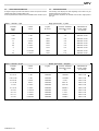
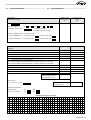
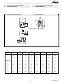
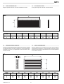
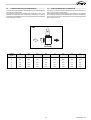
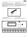
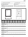
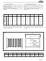
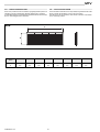
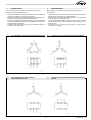
MTV
Manuale tecnico unità termoventilanti modulari MTV
I
Technical manual modular air conditioning unit MTV
GB
FC/N
MTV
INDEX
INDICE
1
Generalità ...................................................................... pag. 3
1
Main features ............................................................... pag. 3
1.1
Componenti costruttivi ..................................................... pag. 3
1.1
Constructive components ............................................... pag. 3
1.2
Versioni e orientamenti ................................................. pagg. 4/5
1.2
Versions and positioning of the unit ............................ pagg. 4/5
1.3
Caratteristiche tecniche nominali .................................... pag. 6
1.3
Rated technical data ........................................................ pag. 6
1.4
Accessori per sviluppo orizzontale / verticale ............... pag. 8
1.4
Options for horizontal / vertical units .............................. pag. 8
2
Scelta dell'unità ............................................................ pag. 9
2
Unit selection ................................................................ pag. 9
2.1
Diagramma di selezione ................................................... pag. 9
2.
Selection diagram ............................................................ pag. 9
2.2
Rese batterie in riscaldamento ....................................... pag. 10
2.2
Heating coil capacity ...................................................... pag. 10
2.3
Rese batterie in raffreddamento .................................... pag. 11
2.3
Cooling coil capacity ....................................................... pag. 11
2.4
Perdite di carico .............................................................. pag. 12
2.4
Air pressure drop ........................................................... pag. 12
2.4.1
Perdite di carico componenti interni all'unità .................. pag. 12
2.4.1
Unit internal components air pressure drop .................. pag. 12
2.4.2
Perdite di carico accessori ............................................. pag. 12
2.4.2
Accessories air pressure drop ..................................... pag. 12
2.5
Caratteristiche di ventilazione ........................................ pag. 13
2.5
Ventilation features ........................................................ pag. 13
2.6
Caratteristiche motori ..................................................... pag. 14
2.6
Motors features .............................................................. pag. 14
2.7
Modulo di selezione ........................................................ pag. 15
2.7
Selection module ............................................................. pag. 15
3
Descrizione e dimensioni di ingombro ................. pag. 16
3
Description and overall dimension ........................ pag. 16
3.1
Dimensioni unità base ..................................................... pag. 16
3.1
Base unit dimension ....................................................... pag. 16
3.1.1
Modelli a sviluppo orizzontale ........................................ pag. 16
3.1.1
Horizontal models ........................................................... pag. 16
3.1.2
Modelli a sviluppo verticale ............................................. pag. 17
3.1.2
Vertical models ............................................................... pag. 17
3.2
Griglia di ripresa GAS ..................................................... pag. 18
3.2
Inlet air grille GAS ........................................................... pag. 18
3.3
Serranda di taratura ST .................................................. pag. 18
3.3
Regulating damper ST .................................................... pag. 18
3.4
Camera di miscela a 2 serrande CM .............................. pag. 19
3.4
Mixing chamber with 2 dampers CM .............................. pag. 19
3.5
Sezione filtrante ad alta efficienza TS ........................... pag. 20
3.5
High efficiency filter section TS ..................................... pag. 20
3.5.1
Estrazione del filtro ......................................................... pag. 20
3.5.1
Filter extraction ............................................................... pag. 20
3.6
Separatore di gocce ....................................................... pag. 21
3.6
Droplet eliminator ............................................................ pag. 21
3.7
Plenum di mandata PMA ................................................. pag. 21
3.7
Outlet air plenum PMA .................................................... pag. 21
3.8
Sezione di post-riscaldamento SBC ............................... pag. 22
3.8
Re-heating section SBC ................................................. pag. 22
3.9
Silenziatore a setti SS .................................................... pag. 23
3.9
Noise absortion silencer SS ........................................... pag. 23
3.10
Griglia di mandata BRM ................................................... pag. 24
3.10
Outlet air grille BRM ........................................................ pag. 24
4
Collegamenti elettrici ................................................ pag. 25
4
Wiring diagrams ......................................................... pag. 25
4.1
Collegamento a motore trifase singola velocità ............. pag. 25
4.1
Connection to a 3 phase single speed motor ................ pag. 25
4.2
Collegamento a motore trifase doppia velocità
4.2
Connection to a 3 phase double speed 4/6 poles
motor ............................................................................... pag. 25
4/6 poli ............................................................................. pag. 25
5
5
Identificazione della unità ......................................... pag. 26
UC66000003 - 00
2
Unit identification ........................................................ pag. 26
1
GENERALITÀ
1
MAIN FEATURES
Le nuove unità di termoventilazione Galletti serie MTV sono progettate
per rispondere ai più ampi standard applicativi in campo civile ed industriale.
Queste unità sono prodotte in otto grandezze per soddisfare portate d’aria
da 2000 a 19000 m3/h.
Grazie alla molteplicità dei possibili orientamenti, agli accessori e alle
dimensioni contenute, le unità Galletti della serie MTV sono molto
versatili e di facile installazione anche in spazi ristretti.
La possibilità di funzionamento orizzontale o verticale consente soluzioni
di installazione molto ampie.
The Galletti series MTV fan coil units are typically designed to mach with
various civil and idustrial applications.
These units are produced in eight sizes, ranging from 2000 to 19000
m3/h nominal air flow rates.
The multiple sided return air intakes and supplied, and the contained
dimensions, render the Galletti series MTV units very versatile and easy
to install within any available space.
These untis may be installed vertically or horizzontally which will allow a
wider installation solutions.
1.1
1.1
COMPONENTI COSTRUTTIVI
CONSTRUCTIVE COMPONENTS
•
La struttura è realizzata con profili di acciaio e pannellatura sandwich
a doppio guscio, isolati internamente con materiale fonoassorbente di
spessore 20 mm per i modelli da MTV02 a MTV11 e di spessore 25 mm
per i modelli MTV14 e MTV19;
•
The framework is made of galvanized steel profiles and double skin
panels, internally insulated with soundproof material with a thickness
of 20 mm for the models from MTV02 to MTV 11 and of 25 mm for the
models from MTV14 to MTV19.
•
I pannelli standard, realizzati in acciao preverniciato, sono dotati di
guarnizione autoadesiva e vengono fissati al telaio tramite viti in acciaio;
nei vani ispezionabili vengono muniti di chiusura di sicurezza con viti
ad 1/4 di giro;
•
The standard panels, made of pre-painted steel, are supplied of a selfsealing lining and are fixed to the framework with steel screws; they
can be removed by 1/4 turn screws.
•
•
Le macchine appoggiano su piedi in acciaio zincato di forte spessore,
sagomato in modo da assicurare una solida base di appoggio e per
consentire in tutta sicurezza il trasporto e la movimentazione in cantiere
The units stand on galvanized steel foot of suitable thickness, shapes
to have a solid bearing base to insure a safety freight and safety
shifting.
•
I ventilatori sono di tipo centrifugo a doppia aspirazione, con girante a
pale in avanti equilibrata staticamente e dinamicamente, montata su di
un albero rotante con cuscinetti lubrificati;
•
Double intake centrifugal fans with statically and dinamically balanced
impellers, mounted on a rotating drive shaft with lubricaficated bearings.
•
I motori sono di tipo asincrono trifase con rotore a gabbia caratterizzati
da grado di protezione IP55 ed avvolgimenti in classe F; sono alloggiati
su una apposita slitta che permette sia il fissaggio sia la regolazione
della cinghia di trasmissione.
L'unità standard utilizza motori a 1 velocità (4 poli) e su richiesta
possono essere montati motori a 2 velocità (4/6 poli);
The motor is a three-phase asynchronous type, with cage
rotor, IP55 degree protection, class F winding and it is mounted on a
specific slide that allows both the mounting and regulation of the
transmission belt. The standard unit is equipped with single-speed
motor (4 poles); upon request it can be equipped with double-speed
motor (4/6 or 4/8 poles).
•
La trasmissione viene realizzata mediante cinghie e pulegge a gole
trapezoidali con bussole conica di serraggio.
The transmission is carried out through a trapezoidal belt and pulley,
with conical bushing tightening.
•
Il gruppo moto-ventilante viene posizionato su di un unico supporto
ammortizzato, realizzato in robusta lamiera di acciaio zincato, montato
su supporti in gomma dura che permettono di assorbire tutte le
vibrazioni causate dalla rotazione;
The fan-motor group is placed on single shock absorbing support,
made of an heavy zinc-plated steel sheets, mounted on durable rubber
supports that allows to absorb the vibrations caused by the fan
rotation.
•
The heat exchangers are made of copper tube and mechanically
beaded aluminum fins, with threaded collectors and framework in cast
sheet steel panels, water pressure tested with dry air at 30 Bar.
•
The electric heater are made of armoured elements mounted in a
metallic frame, complete with connection board and safety thermostat.
•
The filter section is constructed with cell blocks of class G3.
•
•
•
•
Le batterie di scambio termico, per funzionamento ad acqua, vengono
realizzate con tubo in rame a pacco alettato in alluminio mandrinato
meccanicamente, collettori filettati e telaio in lamiera stampata di
acciaio, collaudate a tenuta in acqua con aria secca alla pressione di
30 bar:
- 2 ranghi solo per riscaldamento
- 4 ranghi e 6 ranghi per raffreddamento e riscaldamento;
•
Le batterie di riscaldamento elettriche sono costruite da elementi
corazzati montati su un telaio metallico, complete di quadro di
collegamento e termostato di sicurezza:
•
La sezione filtrante è realizzata con uno studio di celle a setto sintetico
ondulato classe G3 (efficienza 85% ponderale - EU3).
3
UC66000003 - 00
MTV
1.2
VERSIONI E ORIENTAMENTI DELL'UNITÀ
1.2
VERSIONS AND POSITIONING OF THE UNIT
BFH
Versione BFH
Sviluppo orizzontale con batteria unica di riscaldamento e/o di raffreddamento; per impianti a 2 tubi.
Version BFH
Horizontal developement with single heating and/or cooling coil; for 2 pipe
systems.
BUH
Versione BUH
Sviluppo orizzontale con batteria unica di riscaldamento e/o di raffreddamento, per impianti a 2 tubi.
Version BUH
Horizontal developement with single heating and/or cooling coil; for 2 pipe
systems.
E
Versione E
Sviluppo orizzontale con batteria di riscaldamento e/o raffreddamento e
batteria elettrica di riscaldamento; per impianti a 2 tubi.
Version E
Horizontal developement with heating/cooling water coil and an electric
heater; for 2 pipe systems.
S
Versione S
Sviluppo orizzontale con batteria unica di riscaldamento e/o di raffreddamento e separatore di gocce; per impianti a 2 tubi.
UC66000003 - 00
Version S
Horizontal developement with heating/cooling water coil and droplet
eliminator; for 2 pipe systems.
4
BDH
Versione BDH
Sviluppo orizzontale con batteria di riscaldamento e batteria di raffreddamento; per impianti a 4 tubi.
Version BDH
Horizontal developement with heating and cooling water coils; for 4 pipe
system.
BFV
Versione BFV
Sviluppo verticale con batteria unica di riscaldamento e/o raffreddamento;
per impianti a 2 tubi.
Version BFV
Vertical developement with heating/cooling single water coil; for 2 pipe
systems.
5
UC66000003 - 00
MTV
1.3
CARATTERISTICHE TECNICHE NOMINALI
MODELLO / MODEL
1.3
RATED TECHNICAL DATA
002
003
005
006
008
011
014
019
Portata aria / Air flow
m3/h
2000
3100
4400
5700
8000
11000
14000
19000
Pressione statica utile*
Pa
150
150
200
200
200
250
250
250
G/1
1020
1140
1080
860
720
660
800
690n
kW
0,37
0,55
1,1
1,1
1,5
2,2
3
4
A
1,05
1,5
2,6
2,6
3,4
5
6,4
8,5
IP
55
55
55
55
55
55
55
55
F
F
F
F
F
F
F
F
Available static pressure*
n° giri ventilatore
n° of rotation of the fan
Potenza all'asse
Axle power available
Corrente massima assorbita
Maximum current absorbed
Grado di protezione motore
Motor protection degree
Classe di isolamento
Insulation class
Alimentazione elettrica
V / Ph / Hz
400 / 3 / 50
Power supply
SCAMBIATORE DI CALORE
HEAT EXCHANGER
Superficie frontale
m2
0,248
0,344
0,420
0,420
0,525
0,525
0,630
0,748
kW
12,3
18,8
25,4
32,3
47,6
65,5
85,0
105
kPa
5,0
12,1
5,7
7,2
13,3
11,1
19,4
5,2
l/h
1060
1620
2180
2780
4100
5640
7310
9100
kW
9,35
15,5
22,0
26,1
40,0
47,1
65,5
90,5
kW
7,20
11,5
16,3
19,8
29,6
37,2
50,4
67,9
kPa
7,6
21,6
26,9
21,6
23,1
6,8
12,6
21,2
l/h
1600
2660
3790
4500
6880
8120
10840
15570
kW
20,2
31,3
44,4
55,8
80,7
105
137
186
kPa
7,3
18,5
22,9
20,4
19,7
7,1
11,3
18,7
l/h
1,73
2,69
3,82
4,80
6,94
9,09
11,8
16,0
Surface area
SCAMBIATORE DI CALORE 2R
HEAT EXCHANGER 2R
Potenza termica2
Heating capacity
2
Perdita di carico lato acqua
Water pressure drop
Portata acqua / Water flow
SCAMBIATORE DI CALORE 4R
HEAT EXCHANGER 4R
Resa frigorifera1
Cooling capacity
1
Resa frigorifera sensibile
Sensible cooling capacity
Perdita di carico lato acqua
Water pressure drop
Portata acqua
Water flow
Resa termica2
Heating capacity
2
Perdita di carico lato acqua
Water pressure drop
Portata acqua
Water flow
*
Valutata alla portata nominale con batteria a 4 ranghi
*
Value at rated flow with 4 rows coil
1
Temperatura acqua 7/12°C
Temperatura aria 27°C a bulbo secco, 19°C a bulbo umido (47% umidità
relativa)
1
Water temperature 7/12°C
Air temperature 27°C dry bulb, 19°C wet bulb (47% relative humidity)
2
2
Temperatura acqua 70/60°C, temperatura aria 20°C
Water temperature 70/60°C,
Inlet air temperature 20°C
UC66000003 - 00
6
MODELLO / MODEL
002
003
005
006
008
011
014
019
kW
11,3
16,7
25,4
32,3
44,4
59,3
80,8
113
kW
8,70
13,0
19,0
24,2
34,2
45,6
60,6
83,6
kPa
5,4
4,8
9,4
11,8
5,5
7,4
8,4
14,7
l/h
1950
2880
4370
5560
7650
10200
13900
19590
kW
24,4
36,6
52,1
66,7
94,9
129
166
225
kPa
6
6
10
11
5
6
9
16
l/h
2140
3220
4580
5870
8345
11370
14620
19800
SCAMBIATORE DI CALORE 6R
HEAT EXCHANGER 6R
Resa frigorifera1
Cooling capacity1
Resa frigorifera sensibile
Sensible cooling capacity
Perdita di carico lato acqua
Water pressure drop
Portata acqua
Water flow
Resa termica2
Heating capacity2
Perdita di carico lato acqua
Water pressure drop
Portata acqua
Water flow
1
Temperatura acqua 7/12°C
Temperatura aria 27°C a bulbo secco, 19°C a bulbo umido (47% umidità
relativa)
2
Temperatura acqua 70/60°C, temperatura aria 20°C
1
Water temperature 7/12°C
Air temperature 27°C dry bulb, 19°C wet bulb (47% relative humidity)
2
Water temperature 70/60°C,
Inlet air temperature 20°C
Batteria elettrica / Electric coil
Resa termica
kW
n° stadi / n° stage
Alimentazione elettrica
3
4
5
9
14
20
25
30
1
1
1
2
2
3
3
3
V / ph / Hz
400 / 3 / 50
Power supply
7
UC66000003 - 00
MTV
1.4
ACCESSORI PER SVILUPPO ORIZZONTALE / VERTICALE
1.4
OPTIONS FOR HORIZONTAL / VERTICAL UNITS
GAS
ST
CM
TS
SBC
SS
PMA
BRM
SG
Griglia di aspirazione
Serranda di taratura
Camera di miscela
Sezione filtro a tasche rigide
Sezione batteria di post-riscaldamento ad acqua o elettrica
Sezione silenziatore a setti fonoassorbenti
Plenum di mandata
Griglia di mandata
Separatore di gocce
Puleggia variabile (contattare la sede)
Tettuccio per esterno (contattare la sede)
GAS
ST
CM
TS
SBC
SS
PMA
BRM
SG
Inlet grille
Setting air louvre
Mixing box
Filter section with rigid bag filters
Post-heating water or electric coil section
Noise absorption silencer section
Outlet plenum
Outlet grille
Droplet eliminator
Adjustable pulley (contact sales department)
Antirain canopy (contact sales department)
Griglia di aspirazione GAS
Inlet grille GAS
Serranda di taratura ST
Setting air louvre ST
Unità base
Base unit
Camera di miscela CM
Mixing box CM
Prefiltri + filtri a tasche TS
Pre-filter + rigid bag filters TS
Sezione batteria di post-riscaldamento SBC
Post-heating coil section SBC
Silenziatore SS
Silencer SS
Plenum di mandata PMA
Outlet plenum PMA
Griglia di mandata BRM
Outlet grille BRM
Griglia di mandata BRM
Outlet grille BRM
Plenum di mandata PMA
Outlet plenum PMA
Silenziatore SS
Silencer SS
Unità base
Base unit
Filtri a tasche TS
Bag filters TS
Griglia di aspirazione GAS
Inlet grille GAS
Serranda di taratura ST
Setting air louvre ST
Camera di miscela CM
Mixing box CM
UC66000003 - 00
8
Batteria di post-riscaldamento SBC
Post-heating coil section SBC
2
SCELTA DELL'UNITÀ
2
UNIT SELECTION
Una selezione diversa da quella standard può essere facilmente effettuata utilizzando le tabelle di questa sezione.
La scelta della macchina in grado di soddisfare le particolari esigenze può
essere eseguita seguendo, una procedura di selezione semplificata che
riguarda gli elementi principali che la compongono:
1
selezione della grandezza
2
scelta e verifica della batteria
3
scelta degli accessori
4
calcolo delle perdita di carico
5
scelta della sezione ventilante
A different selection's unit from the standard one may be easily
achieved by consulting the chart in this section.
The selection of the machine able to satisfy the required specifications
may be achieved following the simplified selection's procedure.
1
size selection
2
choice or verification of coil section
3
accessory choice
4
pressure drop calculation
5
fan section choice
2.1
2.1
DIAGRAMMA DI SELEZIONE
Velocità dell'aria m/s - Air speed m/s
Il diagramma permette di selezionare l'unità in funzione della portata aria
richiesta e della sua velocità sulla sezione frontale della batteria.
Al momento della scelta è necessario tenere in considerazione che
velocità dell'aria elevate consentono di dimensionare unità piccole e poco
costose, ma che portano inevitabilmente a livelli di rumorosità più elevati.
Sul diagramma sono evidenziati i limiti relativi alla velocità dell'aria sulla
sezione frontale della batteria sia per il funzionamento in riscaldamento sia
per il funzionamento in raffreddamento.
002
003
005
SELECTION DIAGRAM
On the diagram, we indicated the various air speed limits on the frontal coil
section, for cooling and heating operations.
During the choice, it is important to consider that the high air speed allowed
to select smallest and more economic units, but it is inevitable that the noise
level will highly increase.
006
008
011
014
019
Portata aria m3/h - Air Flow m3/h
Limite per il funzionamento in riscaldamento
Limit of the heating possibility
Limite per il funzionamento in raffreddamento con separatore di gocce
Limit of the cooling possibility with droplet separator
9
UC66000003 - 00
MTV
2.2
RESE BATTERIE IN RISCALDAMENTO
2.2
MODELLO
VELOCITÀ
PORT. ARIA
N. RANGHI
MODEL
SPEED
AIR FLOW
N. ROWS
[m/s]
[m 3/h]
2,3
2.100
2,5
2.200
2,75
2.500
3,0
2.700
2,3
2.900
2,5
3.100
2,75
3.400
3,0
3.700
2,3
4.000
2,5
4.300
2,75
4.800
3,0
5.200
2,3
5.000
2,5
5.400
2,75
5.900
3,0
6.500
2,3
7.500
2,5
8.100
2,75
8.900
3,0
9.700
2,3
9.900
2,5
10.800
2,75
11.900
3,0
13.000
2,3
12.700
2,5
13.800
2,75
15.100
3,0
16.500
2,3
16.800
2,5
18.300
2,75
20.100
3,0
21.900
002
003
005
006
008
011
014
019
*Portata
acqua
*Potenza
termica
**Temp. uscita
aria
**Portata
acqua
**Perdita
di carico
acqua
**Potenza
termica
*Heating
capacity
**Outlet temp. **Water flow
air
**Heating
capacity
[m3/h]
**Water
pressure
drop
[kPa]
[kW]
[°C]
[°C]
[m3 /h]
2
4
2
4
2
4
2
4
24,1
41,0
22,7
40,1
21,2
39,3
20,4
37,2
1,79
2,84
1,79
2,97
1,92
3,25
2,01
3,35
13
18
13
19
14
22
16
24
20,9
33
20,8
34,6
22,3
37,8
23,4
38,9
37,4
49,5
37,4
48,7
36,3
47,1
35,7
46,6
1,08
1,82
1,13
1,85
1,20
1,99
1,24
2,11
5
8
6
8
6
9
7
10
12,5
21,2
13,1
21,5
13,9
23,1
14,4
24,5
2
4
2
4
2
4
2
4
24,1
41,8
24,1
40,9
22,2
39,2
21,2
37,9
2,48
3,99
2,65
4,19
2,71
4,43
2,84
4,67
26
37
29
40
30
44
33
49
28,8
46,4
30,8
48,7
31,6
51,4
33,1
54,3
38,1
50
37,8
49,5
36,9
48,1
36,3
47,5
1,54
2,56
1,62
2,69
1,69
2,81
1,77
3,00
11
17
12
18
13
20
14
22
17,9
29,8
18,8
31,3
19,7
32,6
20,6
34,8
2
4
2
4
2
4
2
4
24,1
42,7
22,7
41,0
21,2
39,3
20,4
38,0
3,42
5,61
3,50
5,81
3,69
6,25
3,88
6,57
13
46
13
48
15
55
16
60
39,7
65,3
40,7
67,6
42,9
72,7
45,1
76,4
37,8
50,1
37,4
49,5
36,3
48,1
35,7
47,6
2,09
3,54
2,20
3,73
2,30
3,97
2,40
4,22
5
20
6
22
6
25
7
27
24,3
41,1
25,6
43,4
26,7
46,1
27,9
49
2
4
2
4
2
4
2
4
24,1
41,9
22,7
41,0
21,7
39,3
20,4
38,0
4,27
6,89
4,39
7,30
4,62
7,68
4,85
8,21
16
39
16
43
18
47
19
53
49,7
80,1
51,1
84,9
53,7
89,3
56,4
95,5
37,8
49,5
37,4
49,2
36,3
48,1
35,7
47,1
2,61
4,34
2,77
4,63
2,83
4,88
3,00
5,17
6
17
7
19
7
21
8
23
30,4
50,5
32,2
53,9
32,9
56,7
34,9
60,2
2
4
2
4
2
4
2
4
24,1
42,7
23,2
41,0
22,2
39,3
21,2
38,0
6,41
10,53
6,71
10,95
7,10
11,59
7,46
12,26
30
41
32
44
36
49
39
54
74,5
122
78,1
127
82,6
134
86,7
142
38,1
50,1
37,4
49,5
36,6
48,1
36
47,1
3,99
6,63
4,15
7,03
4,34
7,36
4,56
7,72
13
18
14
20
15
22
16
24
46,4
77,1
48,3
81,7
50,5
85,5
53
89,8
2
4
2
4
2
4
2
4
24,1
41,9
23,9
40,1
21,7
39,3
21,2
37,2
8,46
13,64
8,95
14,33
9,32
15,49
9,99
16,12
23
15
25
16
27
18
31
20
98,3
158
104,1
166
108
180
116
187
38,1
49,5
37,4
48,1
36,6
47,1
36
46,6
5,27
8,59
5,54
8,93
5,81
9,47
6,11
10,15
10
6
11
7
12
8
13
9
61,3
99,9
64,4
103
67,5
110
71
118
2
4
2
4
2
4
2
4
24,6
41,9
24,1
40,1
22,2
39,3
21,2
38,0
11,05
17,49
11,79
18,31
12,05
19,66
12,68
20,84
40
23
45
25
47
28
52
31
128,5
203,4
137,1
212,9
140,2
228,6
147,5
242,4
38,44
49,52
37,76
48,65
37,43
47,59
36,29
47,07
6,89
11,02
7,21
11,62
7,74
12,25
7,90
13,13
17
10
19
11
21
12
22
14
80,1
128,2
83,8
135,1
90
142,4
91,9
152,7
2
4
2
4
2
4
2
4
24,1
42,7
22,2
41,0
21,2
39,3
19,9
38,0
14,35
25,58
14,61
24,74
15,45
26,17
16,03
27,67
12
37
12
41
13
45
14
50
166,9
274,2
169,9
287,7
179,7
304,3
186,4
321,7
37,43
50,08
36,6
49,52
35,99
48,11
35,69
47,07
8,61
14,86
8,93
15,88
9,45
16,61
10,10
17,43
5
16
5
19
6
20
6
22
100,1
172,8
103,9
184,7
109,9
193,2
117,5
202,7
acqua = 70 / 60°C
water = 70 / 60°C
** Temperatura ingresso aria = 20°C
** Inlet air temperature = 20°C
acqua = 70 / 60 °C
water = 70 / 60°C
*Outlet temp. *Water flow
air
*Perdita
di carico
acqua
*Water
pressure
drop
[kPa]
* Temperatura ingresso aria = -5°C
* Inlet air temperature = -5°C
UC66000003 - 00
*Temp.uscita
aria
HEATING COIL CAPACITY
10
[kW]
2.3
RESE BATTERIE IN RAFFREDDAMENTO
2.3
COOLING COIL CAPACITY
MODELLO
VELOCITÀ
PORT. ARIA
N. RANGHI
*Temp-UR
aria uscita
*Portata
acqua
*Perdita
di carico
acqua
*Potenza
frigorifera
**Temp-UR
uscita aria
**Portata
acqua
**Perdita
di carico
acqua
**Potenza
frigorifera
MODEL
SPEED
AIR FLOW
N. ROWS
*Temp-UR
outlet air
*Water flow
*Cooling
capacity
**Temp-UR.
outlet air
**Water flow
[m3/h]
[°C]
[m3/h]
[kW]
[°C]
[m3/h]
**Water
pressure
drop
[kPa]
**Cooling
capacity
[m/s]
*Water
pressure
drop
[kPa]
2,3
2.100
2,5
2.200
2,75
2.500
3,0
2.700
4
6
4
6
4
6
4
6
18,1 - 80
15,0 - 87
18,1 - 80
15,4 - 87
19,9 - 78
16,0 - 85
19,2 - 77
16,5 - 84
3,09
3,82
3,24
3,88
3,44
4,25
3,65
4,42
24,3
18
26,4
18,6
29,4
21,8
32
23,4
18,0
22,2
18,8
22,6
20,0
10,0
21,2
25,7
16,5 - 78
14,5 - 86
16,7 - 77
14,5 - 86
17,2 - 76
15,1 - 84
17,5 - 75
15,3 - 83
1,67
2,02
1,71
2,12
1,85
2,25
1,93
2,38
8,1
5,8
8,5
6,3
9,8
7,0
10,5
7,8
9,7
11,7
10,0
12,3
10,8
13,1
11,2
13,8
2,3
2.900
2,5
3.100
2,75
3.400
3,0
3.700
4
6
4
6
4
6
4
6
17,5 - 80
15,0 - 87
17,8 - 80
15,4 - 86
18,3 - 79
16,0 - 85
18,6 - 78
16,3 - 85
4,52
5,27
4,74
5,47
5,01
5,78
5,29
6,17
55,3
14,1
60,2
15
66,4
16,5
73,2
18,6
26,3
30,7
27,6
31,8
29,1
33,6
30,8
35,9
16,0 - 78
14,5 - 86
16,1 - 77
14,5 - 85
16,6 - 76
15,0 - 84
16,4 - 75
15,3 - 83
2,51
2,79
2,66
2,88
2,80
3,11
2,94
3,26
19,4
4,5
21,8
5,1
23,6
5,5
25,7
6,0
14,6
16,2
15,5
16,7
16,3
18,1
17,1
19,0
2,3
4.000
2,5
4.300
2,75
4.800
3,0
5.200
4
6
4
6
4
6
4
6
17,3 - 81
14,8 - 87
17,8 - 80
15,1 - 87
18,3 - 79
15,5 - 85
18,7 -78
15,8 - 85
6,35
7,41
6,58
7,82
7,07
8,47
7,43
9,01
67,4
24,1
71,7
26,5
81,6
30,6
89,2
34,1
36,9
43,1
38,2
45,5
41,1
49,3
43,2
52,4
15,9 - 78
13,9 - 86
16,1 - 77
14,3 - 85
16,6 - 76
14,7 - 84
16,9 - 75
15,0 - 83
3,53
4,15
3,72
4,29
3,96
4,61
4,13
4,85
23,6
8,6
26
9,1
29
10,4
31,3
11,3
20,5
24,1
21,6
25,0
23,0
26,8
24,0
28,2
2,3
5.000
2,5
5.400
2,75
5.900
3,0
6.500
4
6
4
6
4
6
4
6
17,7 - 80
14,8 - 87
18,0 - 80
15,1 - 86
18,2 - 79
15,5 - 86
18,8 - 77
15,8 - 85
7,65
9,27
8,11
9,82
8,69
10,41
9,12
11,26
55,4
29,2
61,4
32,4
69,6
35,9
75,8
41,3
44,5
53,9
47,1
57,1
50,5
60,5
53,0
65,5
16,0 - 78
13,9 - 86
16,4 - 77
14,3 - 85
16,8 - 76
14,5 - 84
17,0 - 75
15,0 - 83
4,33
5,18
4,45
5,39
4,68
5,78
5,06
6,06
20
10
21
11
23
13
27
14
25,2
30,1
25,9
31,3
27,2
33,6
29,4
35,3
2,3
7.500
2,5
8.100
2,75
8.900
3,0
9.700
4
6
4
6
4
6
4
6
17,5 - 80
15,0 - 87
17,8 - 80
15,4 - 86
18,3 - 79
16,0 - 85
18,7 - 78
13,6 - 85
11,69
13,64
12,39
14,30
13,11
15,13
13,87
16,18
59
16
66
17
73
19
80
21
68,0
79,3
72,0
83,1
76,2
88,0
80,6
94,1
16,0 - 78
14,5 - 86
16,1 - 77
14,5 - 85
16,7 - 76
15,0 - 84
17,0 - 75
15,3 - 83
6,49
7,21
7,01
7,79
7,20
8,15
7,55
8,55
21
5,0
24
6
25
6,0
27,0
7,0
37,7
41,9
40,7
45,3
41,8
47,4
43,9
49,7
2,3
9.900
2,5
10.800
2,75
11.900
3,0
13.000
4
6
4
6
4
6
4
6
18,0 - 80
15,0 - 87
18,6 - 87
15,4 - 88
19,1 - 60
16,0 - 85
19,4 - 77
16,3 - 85
14,59
18,01
15,15
19,06
16,08
20,23
17,24
21,68
19,0
20,0
21,0
23,0
23,0
25,0
26,0
28,0
84,8
104,7
88,1
110,8
93,5
117,6
100,2
126,1
16,6 - 78
14,3 - 86
17,0 - 77
14,5 - 85
17,3 - 76
15,0 - 84
17,5 - 75
15,3 - 83
7,71
9,70
8,01
10,38
8,50
10,90
9,11
11,46
6,0
7,0
7,0
8,0
7,0
8,0
8,0
9,0
44,8
56,4
46,6
60,4
49,4
63,3
53,0
66,6
2,3
12.700
2,5
13.800
2,75
15.100
3,0
16.500
4
6
4
6
4
6
4
6
17,9 - 80
14,5 - 87
18,2 - 79
15,1 - 86
18,6 - 78
15,5 - 86
19,0 - 77
15,8 - 85
19,07
23,99
20,33
25,10
21,59
26,65
22,72
28,58
32,0
22,0
36,0
24,0
40,0
27,0
43,0
30,
110,8
139,5
118,2
145,9
125,5
154,9
132,1
166,2
16,3 - 78
13,9 - 86
16,6 - 77
14,3 - 85
16,9 - 76
14,5 - 84
17,3 - 75
14,8 - 83
10,46
13,16
10,95
13,78
11,76
14,79
12,24
15,86
11,0
8,0
12,0
8,0
13,0
9,0
14,0
11,0
60,8
76,5
63,7
80,1
68,4
86,0
71,1
92,2
2,3
16.800
2,5
18.300
2,75
20.100
3,0
21.900
4
6
4
6
4
6
4
6
17,5 - 80
14,2 - 87
18,0 - 80
14,6 - 87
18,3 - 79
15,1 - 86
18,8 - 78
15,6 - 85
26,19
32,33
27,47
34,65
29,61
36,56
30,72
38,63
54,0
36,0
58,0
40,0
37,0
45,0
71,0
49,0
152,3
188,0
159,7
200,9
172,2
212,6
178,6
224,7
16,0 - 78
13,6 - 86
16,3 - 77
13,8 - 85
16,7 - 76
14,3 - 84
17,0 - 75
14,5 - 83
14,54
18,29
15,37
19,55
16,25
20,45
17,05
21,96
19,0
13,0
21,0
15,0
23,0
16,0
25,0
18,0
84,5
106,0
89,3
113,0
94,5
118,0
99,2
127,0
002
003
005
006
008
011
014
019
* Temperatura ingresso aria = bs 32°C - ur 50%
* Inlet air temperature = bs 32°C - ur 50%
acqua = 7 / 12 °C
water = 7 / 12 °C
** Temperatura ingresso aria = bs 27°C - ur 47%
** Inlet air temperature = bs 27°C - ur 47%
acqua = 7 / 12 °C
water = 7 / 12 °C
11
[kW]
UC66000003 - 00
MTV
2.4
PERDITE DI CARICO LATO ARIA
2.4
AIR PRESSURE DROP
2.4.1
Perdite di carico dei componenti interni della unità
2.4.1
Unit internal components air pressure drop
SG
S
GA
CM
TS
SS
ST
A
PM
2.4.2
Perdite di carico degli accessori
2.4.2
Accessories air pressure drop
4
3.5
3
2.5
Pr
ilt
ef
ro
G
F
3/
ilte
rG
3
ria
tte
a
B
i/
gh
n
a
2r
il
co
s
ow
2r
ria
te
t
Ba
4
i/
gh
n
ra
4
il
co
s
w
ro
ria
tte
a
B
6
/
hi
g
n
ra
6
il
co
s
w
ro
2
1.5
10
UC66000003 - 00
50
12
100
200
300
2.5
CARATTERISTICHE DI VENTILAZIONE
2.5
Tabella per la selezione della sezione ventilante.
La tabella individua il motore idoneo “kW” a soddisfare una condizione di
portata e pressione totale (la pressione dinamica del ventilatore è già
considerata) per ogni modello di macchina; vengono inoltre riportati il
numero di giri del ventilatore “G/1” e la relativa pressione sonora “dB(A)”
valutata ad 1 metro di distanza.
Modello Velocità Portata
aria
002
003
005
006
008
011
014
019
Fan section selection chart.
The table displays the correct motor “kW” that satisfies the total volume
and pressure for each machine model (the dynamic pressure of the fan
is already taken into consideration); furthermore, it displays the number
of fan revs. “G/1” and the relative noise level “dB(A)” calculated at a
distance of 1 meter.
Pressione statica totale [Pa]
200
Model
VENTILATION FEATURES
300
400
500
600
Speed
[m/s]
Air flow
[m 3/h]
[kW]
[G/1]
[dB(A)]
[kW]
[G/1]
[db(A)]
[kW]
[G/1]
[db(A)]
[kW]
[G/1]
[db(A)]
[kW]
[G/1]
[db(A)]
2,3
2,5
2,75
3,0
2.100
2.200
2.500
2.700
0,37
0,37
0,37
0,55
965
974
1007
1033
56,8
57,6
59,8
61,3
0,37
0,37
0,55
0,55
1158
1161
1177
1193
59,1
59,7
61,5
62,8
0,55
0,55
0,55
0,75
1335
1335
1339
1348
61,1
61,7
63,2
64,3
0,75
0,75
0,75
0,75
1497
1494
1492
1945
63
63,4
64,8
65,8
0,75
0,75
1,1
1,1
1645
1642
1636
1635
64,6
65
66,3
67,2
2,3
2,5
2,75
3,0
2.900
3.100
3.400
3.700
0,55
0,55
0,55
0,75
1069
1091
1129
1171
60,1
61,4
63,3
65,1
0,55
0,55
0,75
0,75
1253
1267
1294
1326
62
63,1
64,7
66,3
0,75
0,75
0,75
1,1
1427
1434
1451
1473
63,7
64,7
66,1
67,6
1,1
1,1
1,1
1,1
1590
1592
1601
1616
65,4
66,2
67,5
68,8
1,1
1,1
1,1
1,5
1743
1742
1745
1753
66,9
67,6
68,8
70
2,3
2,5
2,75
3,0
4.000
4.300
4.800
5.200
0,75
0,75
1,1
1,1
934
961
1012
1055
62,3
63,8
66,2
68,1
1,1
1,1
1,1
1,5
1076
1096
1135
1171
63,9
65,2
67,4
69,2
1,1
1,1
1,5
1,5
1214
1226
1254
1283
65,5
66,6
68,6
70,2
1,1
1,5
1,5
2,2
1347
1352
1370
1392
67
68
69,8
71,2
1,5
1,5
2,2
2,2
1475
1475
1484
1498
68,4
69,3
70,9
72,2
2,3
2,5
2,75
3,0
5.000
5.400
5.900
6.500
1,1
1,1
1,1
1,5
735
745
761
785
59,4
60,7
62,3
64,2
1,1
1,1
1,5
1,5
886
889
896
909
61,7
62,7
64,1
65,8
1,1
1,5
1,5
1,5
1025
1023
1024
1029
63,8
64,7
65,8
67,3
1,5
1,5
2,2
2,2
1152
1148
1144
1144
65,7
66,5
67,5
68,8
2,2
2,2
2,2
2,2
1269
1263
1257
1253
67,4
68,1
69
70,2
2,3
2,5
2,75
3,0
7.500
8.100
8.900
9.700
1,1
1,5
1,5
2,2
615
626
642
662
59
60,4
62,1
63,9
1,5
1,5
2,2
2,2
735
740
749
762
61,2
62,3
63,8
65,3
2,2
2,2
2,2
3
846
847
850
858
63,2
64,1
65,4
66,8
2,2
3
3
3
949
947
946
949
65
65,8
67
68,2
3
3
4
4
1046
1041
1037
1036
66,7
67,4
68,4
69,5
2,3
9.900
2,5 10.800
2,75 11.900
3,0 13.000
1,5
1,5
2,2
2,2
518
525
536
549
60,9
62,3
64,1
65,9
2,2
2,2
2,2
3
628
629
633
641
63,4
64,6
66,1
67,6
2,2
3
3
3
727
725
725
728
65,7
66,7
67,9
69,2
3
3
4
4
817
814
811
811
67,7
68,5
69,7
70,8
4
4
4
5,5
899
895
891
889
69,4
70,2
71,2
72,3
2,3 12.700
2,5 13.800
2,75 15.100
3,0 16.500
2,2
2,2
2,2
3
632
637
647
660
59,6
60,7
62,1
63,7
3
3
3
4
770
770
772
778
62,2
63,1
64,3
65,6
4
4
4
5,5
895
891
888
889
64,5
65,3
66,3
67,4
4
5,5
5,5
5,5
1009
1002
997
994
66,6
67,2
68,1
69
5,5
5,5
-
1115
1106
-
68,4
69
-
2,3 16.800
2,5 18.300
2,75 20.100
3,0 21.800
2,2
2,2
3
3
539
540
545
552
61,6
59,5
64,2
65,6
3
3
4
4
662
668
659
661
64,6
62,9
66,6
67,8
4
4
5,5
5,5
769
777
763
762
67,1
65,6
68,8
69,8
-
-
-
-
-
-
13
UC66000003 - 00
MTV
2.6
CARATTERISTICHE MOTORI
2.6
MOTORS FEATURES
Di seguito vengono riportati i dati relativi ai motori che possono essere
installati sulle sezioni ventilanti delle unità.
Se non espressamente richiesto il motore installato è ad 1 velocità a 4 poli.
The following chart displays the data regarding which motors may be
installed within the fan section unit.
Unless otherwise requested, the installed motor will be a single speed 4
pole type.
Motori a 1 velocità - 4 poli
Single speed motor - 4 poles
Potenza
Power
[kW]
Cassa
Case
N. giri/1
N. revs/1
Corrente assorbita
Absorbed current
[A]
Alimentazione
Power supply
[V / ph / Hz]
0,37
C 71
1350
1.05
230-400 / 3 / 50
0,55
C 80
1360
1.5
230-400 / 3 / 50
0,75
C 80
1360
2.0
230-400 / 3 / 50
1,1
C 90 S
1380
2.6
230-400 / 3 / 50
1,5
C 90 L
1380
3.4
230-400 / 3 / 50
2,2
C 100 L
1410
5.0
230-400 / 3 / 50
3
C 100 L
1410
6.4
230-400 / 3 / 50
4
C 112 M-T
1420
8.5
230-400 / 3 / 50
5,5
C 132 S
1430
11.5
400-660 / 3 / 50
Motori a 2 velocità - 4/6 poli
Double speed motor - 4/6 poles
Potenza
Power
[kW]
Cassa
Case
N. giri/1
Corrente assorbita
Absorbed current
[A]
Alimentazione
Power supply
[V / ph / Hz]
0.26 / 0.075
C 71
1415/960
1.07/0.52
400 / 3 / 50
0.4 / 0.12
C 80
1405/940
1.29/0.46
400 / 3 / 50
0.55 / 0.18
C 80
1420/950
1.75/0.66
400 / 3 / 50
0.8 / 0.29
C 90 S
1425/955
2.14/1
400 / 3 / 50
1.1 / 0.38
C 90 L
1425/955
2.8/1.31
400 / 3 / 50
1.7 / 0.6
C 100 L
1425/950
4.0/1.85
400 / 3 / 50
2.1 / 0.75
C 100 L
1430/955
4.85/2.3
400 / 3 / 50
3.0 / 0.9
C 112 M
1445/960
6.9/2.7
400 / 3 / 50
3.6 / 1.2
C 132 S
1450/965
7.7/3.1
400 / 3 / 50
5.5 / 1.7
C 132 M
1450/965
10.6/4.4
400 / 3 / 50
7.2 / 2.5
C 160 M-T
1450/965
14.9/6.2
400 / 3 / 50
UC66000003 - 00
14
2.7
MODULO DI SELEZIONE
2.7
SELECTION MODULE
UNITA’ BASE
BEARING STRUCTURE
Perdite di carico
Pressure drop
Pa
Lunghezza unità
Lenght
mm
MTV
Versione / Version
BFH
BDH
BUH
Portata aria / Air flow [m3/h]
BFV
E
S
Pressione statica utile /
Available static pressure [Pa]
Sezione di prefiltrazione G3 / Pre-filter section G3
n° ranghi raffreddamento / n° rows cooling mode
Potenza / power [kW]
n° ranghi riscaldamento / n° rows heating mode
Potenza / power [kW]
ACCESSORI
OPTIONS
GAS
Griglia di aspirazione / Inlet air grille
ST
Serranda di taratura / Adjustable intake louwer
CM
Camera di miscela a 2 serrande / Mixing box with 2 louver
TS
Sezione filtro a tasche / Bag filter section
Separatore di gocce / Droplet separator
SBC2 Sezione batteria di post-riscaldamento a 2 ranghi / Re-heating 2 rows section
SBC4 Sezione batteria di post-riscaldamento a 4 ranghi / Re-heating 4 rows section
SBCE Sezione con batteria elettrica / Electric coil section
SS
Silenziatore a setti fonoassorbenti / Silencer with deadening panels
PMA
Plenum di mandata / Outlet plenum
BRM
Griglia di mandata / Outlet grille
Pressione statica utile [Pa]
Total static pressure [Pa]
Motore / Motor
kW - n° poli / kW - n° poles
Lunghezza totale [mm]
Total lenght [mm]
Orientamenti / Positioning
Mandata / Outlet
MO
M90
Attacchi / Connections
DX
SX
Schema dell’unità / Unit sketch
15
UC66000003 - 00
MTV
3
3.1
DESCRIZIONI E DIMENSIONI DI INGOMBRO
DIMENSIONI UNITÀ BASE
3
3.1
DESCRIPTIONS AND OVERALL DIMENSION
BASE UNIT DIMENSION
3.1.1
MODELLI A SVILUPPO ORIZZONTALE
3.1.1
HORIZONTAL MODELS
G Scarico condensa
G Condensate discharge
Lato attacchi sinistro
Left side connections
Lato attacchi
destro
Right side
connections
Modello
Model
002
003
005
006
008
011
014
019
A
850
1030
1240
1240
1530
1530
1850
2130
B
570
570
630
750
870
1110
1180
1320
C
1140
1140
1260
1500
1740
2220
2360
2640
D 2 ranghi / rows
1"
1"
1"
1"
1"
1” 1/4
1” 1/4
2
D 4 ranghi / rows
1”
1”
1”
1”
1” 1/4
2”
2”
2”
D 6 ranghi / rows
1”
1” 1/4
1” 1/4
1” 1/4
2”
2”
2” 1/2
2” 1/2
E
90
90
90
90
90
90
90
90
G
48
48
48
48
48
48
48
48
L1
240
300
340
400
480
560
480
560
L2
270
270
290
350
410
480
410
480
L3
-
-
-
-
-
-
390
460
N1
740
970
1180
1180
1460
1460
1760
2040
N2
510
510
570
690
810
1050
1100
1220
UC66000003 - 00
16
3
3.1
3.1.2
DESCRIZIONI E DIMENSIONI DI INGOMBRO
DIMENSIONI UNITÀ BASE
MODELLI A SVILUPPO VERTICALE
3
3.1
DESCRIPTIONS AND OVERALL DIMENSION
BASE UNIT DIMENSION
3.1.2
VERTICAL MODELS
G Scarico condensa
G Condensate discharge
Modello
Model
002
003
005
006
008
011
014
019
A
570
570
630
750
870
1110
1180
1320
B
1140
1140
1260
1500
1740
2220
2360
2640
C
850
1030
1240
1240
1530
1530
1850
2130
D 2 ranghi / rows
1"
1"
1"
1"
1"
1” 1/4
1” 1/4
2
D 4 ranghi / rows
1”
1”
1”
1”
1” 1/4
2”
2”
2”
D 6 ranghi / rows
1”
1” 1/4
1” 1/4
1” 1/4
2”
2”
2” 1/2
2” 1/2
E
90
90
90
90
90
90
90
90
G
48
48
48
48
48
48
48
48
L1
240
300
340
400
480
560
480
560
L2
270
270
290
350
410
480
410
480
L3
-
-
-
-
-
-
390
460
N1
740
970
1180
1180
1460
1460
1760
2040
N2
510
510
570
690
810
1050
1100
1220
17
UC66000003 - 00
MTV
3.2
GRIGLIA DI RIPRESA GAS
3.2
Griglia di aspirazione aria, ad unico filare di alette fisse inclinate.
GAS
INLET AIR GRILLE GAS
Air inlet grille single main frame with inclined fixed slats.
B
A
3.3
Modello
Model
002
A
600
B
400
003
005
006
008
011
014
019
800
900
1000
1200
1300
1600
1900
400
400
400
500
600
600
700
SERRANDA DI REGOLAZIONE ST
3.3
Permettono la taratura della portata d’aria dell’impianto e vengono realizzate
con alette tamburate a movimento contrapposto, mosse da ingranaggi e
comandate da un perno per l’applicazione del servocomando o da un
comando manuale.
REGULATING DAMPER ST
Allow the regulation of the air capacity of the system, and are built with
of drummed wings operating in a counter-direction movement, complete
with gear movement and pivot, responsible for servo-command application
or for a manual command.
ST
A
B
C
Modello
Model
002
003
005
006
008
011
014
019
A
B
C
410
600
150
410
800
150
410
900
150
410
1000
150
510
1200
150
610
1300
150
610
1600
150
710
1900
150
UC66000003 - 00
18
3.4
CAMERA DI MISCELA CON 2 SERRANDE CM
3.4
La camera di miscela permette la taratura dell’aria ripresa dall’ambiente e
ricircolata con l’aria esterna.
Le 2 serrande consentono un regolazione di portata da 0 a 100%, sono
realizzate ad alette tamburate a movimento contrapposto, mosse da
ingranaggi e comandate da un perno per l’applicazione del servocomando
o da un comando manuale.
MIXING CHAMBER WITH 2 DAMPERS CM
The mixing chamber allows airflow regulation of the room air temperature
and is recycled with the external air.
The 2 dampers permit a volume regulation of 0 to 100%, they are built with
drummed wings operating in a counter-direction movement, complete with
gear movement and a pivot, responsible for servo-command application
or for manual command.
CM
AxB
DxE
C
Modello
Model
002
003
005
006
A
410
410
410
410
510
610
610
710
B
600
800
900
1000
1200
1300
1600
1900
C
570
570
570
570
570
570
570
570
D
410
410
410
410
410
410
410
410
E
600
800
900
1000
1200
1300
1600
1900
19
008
011
014
019
UC66000003 - 00
MTV
3.5
SEZIONE FILTRANTE AD ALTA EFFICIENZA TS
3.5
Indispensabile per garantire la Qualità dell’aria trattata, utilizza filtri a tasche
rigide ad alta efficienza, classe F 7 (eff. media EN 779 85%), realizzati
con media filtrante in carta di microfibre di vetro e telaio in materiale plastico.
HIGH EFFICIENCY FILTER SECTION TS
Indispensable to guarantee the quality of the treated air, employs high
efficiency rigid bag filters, class F 7 (average efficiency EN 779 85%), built
with glass micro-fiber paper filters with frame construction in plastic.
TS
C
Modello
Model
002
003
005
006
008
011
014
019
C
570
570
570
570
570
570
570
570
Numero di celle filtranti
595 x 287
1
595 x 490
2
1
2
2
3
595 x 595
3.5.1
2
Estrazione filtro
3.5.1
Per garantire la massima praticità nelle normali operazioni di manutenzione,
le celle filtranti vengono montate su guide metalliche e sono facilmente
estraibili lateralmente dal portello di ispezione.
3
3
Filter extraction
To insure the maximum possible practicality during maintenance operations,
the filter cells are constructed upon metal guides, to aid extraction from
the lateral inspection panels.
ello
ort
p
re
cca port
o
l
Sb block
Un
UC66000003 - 00
3
3
o
iltr
e f tion
n
zio ac
tra extr
s
E ter
Fil
20
3.6
SEPARATORE DI GOCCE
3.6
L’elemento separatore viene inserito all’interno delle unità in versione S.
Viene realizzato con alette sagomate in materiale plastico, inserite in una
struttura metallica e posto all’interno della vasca di raccolta condensa.
Si tratta di un elemento indispensabile quando si effettuano trattamenti che
comportano la presenza di una notevole quantità di acqua all’interno della
macchina, ad esempio raffreddamento con deumidificazione (in estate)
o umidificazione (in inverno).
I valori consigliati per l’applicazione del separatore di gocce sono indicati
nel diagramma di selezione dell’unità.
DROPLET ELIMINATOR
The element is inserted internally with the unit version S.
It is built with profiled wings in plastic, inserted within a metal frame and
placed inside the condensation drip tray.
This article is extremely important when air treatment opertion is producing
water in considerable quantities inside the apparatus, for example, cooling
with dehumidification (in summer) or humidity (in winter).
The suggested values for the application of the droplet separator are
displayed in the Unit selection chart.
SG
3.7
PLENUM DI MANDATA PMA
3.7
Il plenum offre la possibilità di ruotare il flusso di 90° .
Il foro, di dimensioni adeguate, prevede l’inserimento della griglia di
mandata.
PMA
OUTLET PLENUM AIR PMA
The plenum allows the possibility to rotate the airflow by 90° .
The opening, of adequate dimensions, provides for the insertion of a outlet
grill.
B
A
C
Modello
Model
002
003
005
006
008
011
014
019
A
B
C
600
200
570
800
250
570
900
300
570
1000
300
570
1200
350
570
1300
400
570
1600
400
570
1900
400
570
21
UC66000003 - 00
MTV
3.8
SEZIONE DI POST - RISCALDAMENTO SBC
3.8
La sezione di post riscaldamento può essere realizzata in 3 soluzioni:
SBC2 con batteria ad acqua calda a 2 ranghi
SBC4 con batteria ad acqua a 4 ranghi
SBCE con batteria di resistenze elettriche
Le prestazioni delle batterie ad acqua a 2 e 4 ranghi sono le stesse indicate
nel paragrafo 2.2
Le prestazioni delle batterie elettriche sono indicate nella tabella, richiedono
linea trifase 400/3/50, e vengono fornite complete di termostati di sicurezza
e quadro di collegamento. La protezione della linea deve essere eseguita
a cura dell’installatore.
RE - HEATING SECTION SBC
The reheating section may be organized in three different solutions:
SBC2 with 2 rows hot water coil.
SBC4 with 4 rows water coil
SBCE with electrical coil
The performance 2 – 4 rows water coil are the same as demonstrated in
para. 2.2
The performance of the electrical coil is indicated in chart, a triphase 400/
3/50 line is required, and is supplied complete with security thermostat and
connection board. Safety protection is the responsibility of the installer.
SBC
A
A
Modello
Model
002
003
005
006
008
011
014
019
A
570
570
570
570
570
570
570
570
MODELLO / MODEL
002
003
005
006
008
011
014
019
3
4
5
4,5
7
6,7
8,4
10
14
13,3
16,7
20
21
20
25
30
BATTERIA ELETTRICA AD 1 STADIO
ELECTRIC COIL 1 STAGE
Potenza termica
kW
Heating capacity
Alimentazione elettrica
V / ph / Hz
400 / 3 / 50
Power supply
BATTERIA ELETTRICA AD 2 STADI
ELECTRIC COIL 2 STAGES
Potenza termica
kW
6
8
10
9
Heating capacity
Alimentazione elettrica
V / ph / Hz
400 / 3 / 50
Power supply
BATTERIA ELETTRICA AD 1 STADIO
ELECTRIC COIL 1 STAGE
Resa frigorifera
kW
9
12
15
13,5
Cooling capacity
Alimentazione elettrica
V / ph / Hz
400 / 3 / 50
Power supply
UC66000003 - 00
22
3.9
SILENZIATORE A SETTI SS
3.9
Possono essere installati sia in mandata che in aspirazione e sono
indispensabili per abbattere il rumore prodotto principalmente dal
funzionamento del ventilatore.
Sono realizzati a setti fonoassorbenti, costruiti con strati multipli di lana
minerale rivestita con una pellicola antisfaldamento.
L’attenuazione media in funzione della banda d’ottava è rappresentata
nella tabella.
Frequenza (Hz)
Frequency (Hz)
Modello
Model
NOISE ABSORBTION SILENCER SS
Noise absorption silencers may be installed both in outlet and in inlet, and
are very important to dampen the noise produced by the operation of the
fan unit.
The silencers are produced in noise absorbing filters, built with multiple
layers of mineral wool covered with an anti-scaling film.
The average noise absorption based upon the octave band is represented
within the chart.
002
003
005
006
008
011
014
019
63
7
7
7
7
7
9
9
9
125
12
12
12
12
12
15
15
15
250
15
15
15
15
15
20
20
20
500
19
19
19
19
19
24
24
24
1000
20
20
20
20
20
27
27
27
2000
16
16
16
16
16
22
22
22
4000
13
13
13
13
13
18
18
18
8000
12
12
12
12
12
16
16
16
È comunque importante tenere sempre presente che la rumorosità emessa
dalla macchina è sempre influenzata dalle caratteristiche di frequenza e
di acustica proprie dell’impianto.
It is important to consider that the noise level emitted from the apparatus
is influenced greatly by the frequency characteristics, and the acoustics
of the system.
SS
A
B
Modello
Model
002
003
005
006
008
011
014
019
A
B
1080
700
1080
700
1080
700
1080
700
1080
700
1620
1000
1620
1000
1620
1000
23
UC66000003 - 00
MTV
3.10
GRIGLIA DI MANDATA BRM
3.10
Dove non è prevista una rete di condotte, la griglia applicata al plenum di
mandata consente la distribuzione dell’aria direttamente in ambiente.
Le alette della griglia sono orientabili per permette di deviare il flusso d’aria
dove si rende maggiormente necessario.
BRM
OUTLET AIR GRILLE BRM
In the case that a conduction net is not provided, the grill fitted to the outlet
plenum permits the distribution of the air into the location.
The slats of the grill are positional, which allows a deviation of the airflow
to the necessary position.
B
A
Modello
Model
002
003
005
006
008
011
014
019
A
B
600
200
800
250
900
300
1000
300
1200
350
1300
400
1600
400
1900
400
UC66000003 - 00
24
4
SCHEMI ELETTRICI
4
WIRING DIAGRAMS
Prima di iniziare qualsiasi operazione assicurarsi che la linea di
alimentazione generale sia selezionata.
Before starting any operation make sure the power supply line is
disconnected.
• I collegamenti elettrici ai quadri di comando devono essere effettuati da
personale specializzato secondo gli schemi forniti.
• Assicurarsi che la tensione e la frequenza riportate sulla targhetta corri
spondano a quelle della linea elettrica di allacciamento.
• È dovere dell’installatore prevedere il montaggio il più vicino possibile
all’unità del sezionatore dell’alimentazione e quanto necessario per la
protezione delle parti elettriche.
• Collegare l’unità ad una efficace presa di terra, utilizzando l’apposita
vite inserita nell’unità stessa.
• The eletrical connections to the control panel must be carried out by quali
fied personnel according to the supplied diagrams.
• Make sure that the voltages and frequency shown on the data plate
correspond to those of the power line.
• It is the installer’s responsability to install the unit as close as possible
to the power switch and when necessary to install a protection for the
electrical parts.
• Connect the unit to an efficient earth, using the supplied screws
inserted in the unit itself.
4.1
COLLEGAMENTO A MOTORE TRIFASE SINGOLA VELOCITÀ
4.1
CONNECTION TO A THREE-PHASE SINGLE SPEED MOTOR
4.2
COLLEGAMENTO A MOTORE TRIFASE A
DOPPIA VELOCITÀ 4/6 POLI
4.2
CONNECTION TO A THREE-PHASE DOUBLE SPEED 4/6 POLES
MOTOR
25
UC66000003 - 00
MTV
5
IDENTIFICAZIONE DELLA UNITÀ
5
Per una corretta individuazione della macchina, è opportuno, in fase
d’ordinazione, specificare tutte le caratteristiche necessarie, come
riportato negli esempi che seguono:
For a precise definition of the machine, it is suggested, when placing the
order, to specify all data as shown on following examples:
Esempio 1
Example 1
MTV008 R42
unità base e sezione batteria
BDH
versione costruttiva
A6
motore
ST
008
accessorio
SS
008
accessorio
Portata aria / Air flow = 7900 m3/h
Pressione statica utile / Static available pressure = 150 Pa
Esempio 2
Example 2
MTV005 R6
unità base e sezione batteria
BFV
versione costruttiva
A6
motore
GAS005
accessorio
PMA005
accessorio
BRM005
accessorio
Portata aria / Air flow = 5000 m3/h
Pressione statica utile / Static available pressure = 180 Pa
UC66000003 - 00
UNIT IDENTIFICATION
26
MTV
UC66000003 - 00
27
40010 Bentivoglio (BO)
Via Romagnoli, 12/a
tel. 051/8908111 r.a.
fax 051/8908122
www.galletti.it


![[A] e) Scheda 2 - Lista Lavorazioni](http://vs1.manualzilla.com/store/data/006108840_1-8ffffbd7c5e49c872e7e4176fdd7c40b-150x150.png)