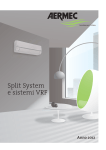
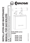
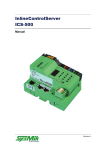
1
Rev 00.00
AC, ACP, EV, RC, RP, VA
Page 1 of 40
INSTRUCTION GUIDE
FOR USE
AC-ACP-EV
RC-RP-VA
AND MAINTENANCE
©| Aerservice S.r.l. | 2013 all rights reserved
The reproduction of this manual, even partial, is strictly forbidden
Rev 00.00
AC, ACP, EV, RC, RP, VA
Page 2 of 40
CONTENTS
Par
Description
0
Analytical index of the operating and maintenance manual
CONTENTS .................................................................................................................................... 2
Analytical index of the operating and maintenance manual ............................................................ 2
INTRODUCTION ............................................................................................................................ 4
Scope of the operating and maintenance manual ............................................................................. 4
Storage of the instruction manual ....................................................................................................... 5
Updating of the Instruction Manual ..................................................................................................... 5
Glossary and pictograms ..................................................................................................................... 6
GENERAL INFORMATION ......................................................................................................... 10
Manufacturer’s identification data..................................................................................................... 10
Machine identification and data plates (if they are present) .......................................................... 11
Declarations ......................................................................................................................................... 11
Guarantee activation form (with repairs by authorised centres) ................................................... 13
THE FANS .................................................................................................................................... 14
General features, applications and reference standards ............................................................... 14
THE FANS .................................................................................................................................... 15
AC series .............................................................................................................................................. 15
THE FANS .................................................................................................................................... 16
ACP series ............................................................................................................................................ 16
THE FANS .................................................................................................................................... 17
EV series ............................................................................................................................................... 17
THE FANS .................................................................................................................................... 18
RC series .............................................................................................................................................. 18
THE FANS .................................................................................................................................... 19
RP series............................................................................................................................................... 19
THE FANS .................................................................................................................................... 20
VA series............................................................................................................................................... 20
©| Aerservice S.r.l. | 2013 all rights reserved
The reproduction of this manual, even partial, is strictly forbidden
AC, ACP, EV, RC, RP, VA
Rev 00.00
Page 3 of 40
INSTALLATION ........................................................................................................................... 21
Positioning and installation ............................................................................................................... 21
INSTALLATION ........................................................................................................................... 23
Vibration insulation ............................................................................................................................. 23
INSTALLATION ........................................................................................................................... 24
Electrical connection .......................................................................................................................... 24
START-UP AND TESTING ......................................................................................................... 26
Start-up ................................................................................................................................................. 26
START-UP AND TESTING ......................................................................................................... 28
Testing .................................................................................................................................................. 28
ACOUSTIC INSULATION OF THE FANS ................................................................................. 29
MAINTENANCE OF THE FAN.................................................................................................... 30
Routine maintenance .......................................................................................................................... 30
MAINTENANCE OF THE FAN.................................................................................................... 32
Malfunctions ......................................................................................................................................... 32
SAFETY........................................................................................................................................ 33
Residual risks ...................................................................................................................................... 33
SAFETY........................................................................................................................................ 36
Instructions for emergency situations .............................................................................................. 36
DECOMMISSIONING .................................................................................................................. 37
Operations to decommision the system ........................................................................................... 37
Details of maintenance operations .......................................................................................... 38
©| Aerservice S.r.l. | 2013 all rights reserved
The reproduction of this manual, even partial, is strictly forbidden
Rev 00.00
AC, ACP, EV, RC, RP, VA
Page 4 of 40
INTRODUCTION
Par
Description
1
Scope of the operating and maintenance manual
This instruction manual is an integral part of the machine and has the purpose of providing all the necessary
information for the following purposes:
•
Raise the awareness of operators as regards safety matters;
•
Safe handling of the machine when packaged and unpackaged;
•
Correct installation of the machine;
•
Thorough knowledge of the machine’s operations and limits;
•
Correct use in total safety;
•
Correct and safe maintenance;
•
Dismantling of the machine in total safety, in compliance with the regulations in force on the health and
safety of workers and the environment.
The people in charge of the company’s departments in which this machine will be installed must,
according to the regulations in force, carefully read the content of this Operating Manual and ensure
that operators and maintenance staff operating and working on the machine read the relevant parts.
The time dedicated to this will be fully rewarded by the correct and safe operation of the machine.
This document is based on the assumption that the systems in which the machine is to be installed are in
compliance with the health and safety at work regulations in force.
The instructions, drawings and documentation contained in this Manual are of a technical confidential nature and
are property of the manufacturer; they may not be reproduced in any way, in part of fully.
If this manual is amended by the manufacturer, the Customer has the responsibility of ensuring that only the
updated versions are available in the points of use.
©| Aerservice S.r.l. | 2013 all rights reserved
The reproduction of this manual, even partial, is strictly forbidden
AC, ACP, EV, RC, RP, VA
Rev 00.00
Page 5 of 40
INTRODUCTION
Par
Description
2
Storage of the instruction manual
The instruction manual must be kept safely and must be handed over to new owners in case of sale throughout the
lifecycle of the machine.
To help preserve the manual in good condition it must be handled with care and with clean hands, and it must not
be placed on dirty surfaces.
It is forbidden to remove, tear out or arbitrarily modify any parts of the manual.
The manual must be stored in an environment away from humidity and heat, in a position near the machines to
which it refers.
Upon the User’s request the Manufacturer shall supply other copies of the machine’s instruction manual.
INTRODUCTION
Par
Description
3
Updating of the Instruction Manual
The manufacturer reserves the right to modify the project and improve the machine without informing customers
and without updating the manual already delivered to the User.
If modifications are made to a machine installed at the customer’s premises, in agreement with the manufacturer,
and which entail the amendment of one or more chapters of the manual, the manufacturer shall send the amended
chapters to the holders of the Instruction Manual and its new overall revision.
According to the instructions that will accompany the updated documentation, the User shall replace the old
chapters in the copies held with the new ones, as well as the first page and table of contents with the new revision
level.
The manufacturer shall be responsible for the descriptions in Italian; translations cannot be thoroughly
checked therefore if there is a difference the Italian version must be considered correct; if this should occur
please contact our sales office that shall make the necessary amendments.
©| Aerservice S.r.l. | 2013 all rights reserved
The reproduction of this manual, even partial, is strictly forbidden
AC, ACP, EV, RC, RP, VA
Rev 00.00
Page 6 of 40
INTRODUCTION
Par
Description
4
Glossary and pictograms
This paragraph lists some terms which are not commonly used or with a meaning different from the common one.
The meaning of the abbreviations and pictograms used is described below. The abbreviations and pictograms are
used to indicate operator qualifications and state of the machine; they provide, in a quick and univocal manner, the
information necessary for the correct and safe use of the machine.
GLOSSARY (Annex I point. 1.1.1 Dir. 2006/42/EC)
HAZARD
A potential source of injury or damage to health;
DANGER ZONE
Any zone within and/or around machinery in which a person is subject to a risk to his health or safety;
EXPOSED PERSON
Any person wholly or partially in a danger zone;
OPERATOR
The person or persons installing, operating, adjusting, maintaining, cleaning, repairing or moving machinery;
RISK
A combination of the probability and the degree of an injury or damage to health that can arise in a hazardous
situation;
GUARD
A part of the machinery used specifically to provide protection by means of a physical barrier;
PROTECTIVE DEVICE
A device (other than a guard) which reduces the risk, either alone or in conjunction with a guard;
INTENDED USE
The use of machinery in accordance with the information provided in the instructions for use;
REASONABLY FORESEEABLE MISUSE
The use of the machinery in a way not intended in the instructions for use, but which may result from readily
predictable human behaviour.
OTHER DEFINITIONS
MAN-MACHINERY INTERACTION
Any situation in which the operator interacts with machinery in any of the operating phases during the lifecycle of
the machinery.
OPERATOR QUALIFICATIONS
Minimum level of skill that an operator must have to carry out the described operation.
©| Aerservice S.r.l. | 2013 all rights reserved
The reproduction of this manual, even partial, is strictly forbidden
AC, ACP, EV, RC, RP, VA
Rev 00.00
Page 7 of 40
NUMBER OF OPERATORS
The suitable number of operators, able to carry out the operation described in an optimal way, as established by
a careful manufacturer analysis, whereby a different number of operators might not make it possible to obtain the
expected result or might endanger the safety of the personnel involved.
STATE OF THE MACHINE
The state of the machine includes operating modes, for example automatic running mode, jog command, stop, etc.,
the condition of the safety devices on the machines such as protection devices provided (or not provided), pressed
emergency button, type of isolation from energy sources, etc.
RESIDUAL RISK
Risks that persist despite the adoption of the protective measures included in the design of the machine and despite
the additional protective devices and measures adopted.
SAFETY DEVICE
Device:
- That carries out a safety function;
- which, when faulty and/or broken, endangers the safety of people.
(e.g. lifting equipment; fixed, mobile, adjustable protective device, etc., electric, electronic, optical, pneumatic,
hydraulic device interlocking a protection device, etc.).
PICTOGRAMS
The descriptions that follow this pictogram contain:
very important information/instructions, in particular as regards safety.
Failure to respect them may lead to:
• danger for the safety of the operators;
• loss of contractual guarantee;
• waiver of the manufacturer’s liabilities.
PICTOGRAMS CONCERNING OPERATOR QUALIFICATIONS
Symbol
Description
Unskilled worker: operator without specific skills that can only carry out simple tasks
following the instructions of qualified technicians.
Driver of lifting and handling means: operator qualified to use machines and material
handling and lifting equipment (strictly following the manufacturer’s instructions), according to
the laws in force in the country of use of the machine.
Mechanical service man: a qualified technician that can manage the machine in normal
conditions, operate in jog mode with the protection devices disabled and work on its
mechanical parts to make the necessary adjustments, repairs and maintenance. Usually he
is not qualified to work on live electrical systems.
Electrical service man: a qualified technician that can use the machine in normal conditions,
operate in jog mode with the protection devices disabled and work on electrical parts to make
the necessary adjustments, repairs and maintenance. He can work on live cabinets and
junction boxes.
Manufacturer’s technician: qualified technician provided by the manufacturer to carry out
complex operations in particular situations, or in any case as agreed with the user. According
to the situation the technician will have mechanical and/or electrical and/or electronic and/or
software skills.
©| Aerservice S.r.l. | 2013 all rights reserved
The reproduction of this manual, even partial, is strictly forbidden
Rev 00.00
AC, ACP, EV, RC, RP, VA
Page 8 of 40
Tab. 0 - 4.1
PICTOGRAMS CONCERNING THE STATE OF THE MACHINE
Pictograms inside a square/rectangle provide INFORMATION.
Symbol
Description
Machine off: with hydraulic or electric power supply disconnected.
Machine on: with hydraulic or electric power supply connected and in safe stop condition with
open mobile protective devices (specifying which); JOG disabled; fixed protection devices
closed.
Machine on: with hydraulic or electric power supply connected and in safe stop condition with
emergency mushroom button pressed or other control with the same function activated,
positioned near the intervention area (specifying the mushroom button or the device to be
used).
Machine moving: in automatic mode, with mobile protection devices closed, the relevant
interlocking devices activated, and the fixed protection devices closed.
Machine moving: in JOG mode, with mobile protection devices closed, the relevant
interlocking devices activated, and the fixed protection devices closed.
Machine moving: in JOG mode, with one or more mobile protection devices, that can be
disabled, open (specifying which) with the relevant interlocking devices activated and fixed
protection devices closed.
Machine on: in stand-by and waiting for functional consent to start (e.g. presence of product),
mobile protection devices closed with safety device closed, and fixed protection devices closed.
Tab. 0 - 4.2
©| Aerservice S.r.l. | 2013 all rights reserved
The reproduction of this manual, even partial, is strictly forbidden
Rev 00.00
AC, ACP, EV, RC, RP, VA
Page 9 of 40
SAFETY SIGNS
•
•
The pictograms inside a triangle indicate DANGER;
The pictograms inside a circle mean PROHIBITION/OBLIGATION.
Symbol
Description
Dangerous electrical voltage
Danger of crushing of upper limbs
Danger of entanglement
Danger of being dragged by machine parts
General hazard
Danger of entanglement in transmission belt
Hot surfaces; danger of burning
Danger of being dragged by impellers or rotating parts
No access to unauthorised people
Do not remove safety devices
Do not manually clean, oil, grease, repair of adjust moving parts
Do not carry out any work without disconnecting the power
Protective gloves must be worn
Safety footwear must be worn
Safety helmets must be worn
Tab. 0 - 4.3
©| Aerservice S.r.l. | 2013 all rights reserved
The reproduction of this manual, even partial, is strictly forbidden
AC, ACP, EV, RC, RP, VA
Rev 00.00
Page 10 of 40
GENERAL INFORMATION
Par
Description
1
Manufacturer’s identification data
MANUFACTURER
Aerservice S.r.l.
REGISTERED OFFICE – ADMINISTRATIVE OFFICE
Via Marconi, 1 Z.I. – 35020 – Legnaro – (PD) – Italy
AFTER SALES/SPARE PARTS SERVICE
Tel. +39 049 641 200
Fax. +39 049 825 2310
E-mail: [email protected]
CALL CENTER
Tel. +39 049 641 200
CONTACTS
Tel. +39 049 641 200
Fax. +39 049 825 2310
E-mail:
•
[email protected]
©| Aerservice S.r.l. | 2013 all rights reserved
The reproduction of this manual, even partial, is strictly forbidden
Rev 00.00
AC, ACP, EV, RC, RP, VA
Page 11 of 40
GENERAL INFORMATION
Par
Description
2
Machine identification and data plates (if they are present)
Each machine is fitted with a CE plate with indelible identification data. All communications with the manufacturer
or technical assistance centres must refer to the said data.
Year of
manufacture
Article code
Article barcode
Serial number
Revision number
of label
Serial number
barcode
The position of the plate on the machine may vary.
GENERAL INFORMATION
Par
Description
3
Declarations
The machine is manufactured in conformity with relevant EC Directives, applicable when the machine is put on
the market.
ANNEX IV Directive 2006/42/EC
The machine does not belong to the category of machines mentioned in Annex IV to directive 2006/42/EC
©| Aerservice S.r.l. | 2013 all rights reserved
The reproduction of this manual, even partial, is strictly forbidden
Rev 00.00
AC, ACP, EV, RC, RP, VA
Page 12 of 40
EC DECLARATION OF CONFORMITY
(Annex IIA DIR. 2006/42/CE)
THE MANUFACTURER
Aerservice S.r.l.
Company
Via Marconi, 1 Z.I.
35020
Padua
Address
Zip code
Province
Legnaro
Italy
City
Country
DECLARES THAT THE MACHINE
Single inlet centrifugal fans
AC, ACP, EV, RC, RP, VA
Description
Model
_ _-_ _ _ _ _ _-_ _ _ _
____
Serial number
Year of manufacture
AC, ACP, EV, RC, RP, VA
Commercial name
Single inlet centrifugal fans for extraction plants
Intended use
IS IN COMPLIANCE WITH THE FOLLOWING DIRECTIVES
Directive 2006/42/EC of the European Parliament and Council of 17 may 2006 on machinery and amending directive 95/16/EC.
Directive 2004/10/8/EC of the European Parliament and Council of 15 December 2004 on the approximation of the laws of the
member States relating to electromagnetic compatibility.
Directive 2006/95/EC of the European Parliament and Council of 12 December 2006 on the approximation of the laws of
Member States relating to electrical equipment designed for use within certain voltage limits.
Reference to harmonised standards:
EN 349:1993+A1:2008, EN 614-1:2006+A1:2009, EN 614-2:2000+A1:2008, EN 626-1:1994+A1:2008, EN 626-2:1996+A1:2008, EN
842:1996+A1:2008, EN 894-1:1997+A1:2008, EN 894-2:1997+A1:2008, EN 894-3:2000+A1:2008, EN 953:1997+A1:2009, EN 10052:2003+A1:2008,
EN 1037:1995+A1:2008, EN 1037:1995+A1:2008, EN 1093-1:2008, EN 1093-4:1996+A1:2008, EN 13478:2001+A1:2008, EN ISO 138491:2008,
EN ISO 13849-2:2008, EN ISO 13850:2008, EN ISO 13857:2008, EN ISO 14121-1:2007, EN ISO 14159:2008
AND DECLARES THAT THE TECHNICAL FILE
Has been compiled by the manufacturer and is kept at:
Aerservice S.r.l. in Via Marconi,1 Z.I. – 35020 – Legnaro – PD – Italy
Place and date of document
The manufacturer
Legnaro, _ _ / _ _ / _ _ _ _
Legal representative
D.C.: DC N-001/00001
©| Aerservice S.r.l. | 2013 all rights reserved
The reproduction of this manual, even partial, is strictly forbidden
Rev 00.00
AC, ACP, EV, RC, RP, VA
Page 13 of 40
GENERAL INFORMATION
Par
Description
4
Guarantee activation form (with repairs by authorized centers)
BUYER’S DETAILS:
COMPANY NAME ▼
_______________________________
Section to be filled in and returned in a sealed
envelope to:
Aerservice S.r.l.
Via Marconi, 1 Z.I.
35020 Legnaro (PD) Italy
BUSINESS/PROFESSION/DEPARTMENT ▼
_______________________________
USER DATA (Surname and Name) ▼
_______________________________
PLACE OF INSTALLATION ADDRESS ▼
_______________________________
ZIP CODE ▼
_________
_________
Telephone ▼
_________
_________
Please enclose also a copy of the purchase
document (delivery note, invoice, receipt) showing
the date of purchase.
Or send a fax to +39 049 825 2310 .
CITY ▼
Fax ▼
e-mail ▼
_________
Purchase date ▼
_________
Model ▼
_________
Serial number ▼
_________
accessory/ies ▼
_________
In accordance with article 10 of Law 675/96 data provided in this form shall be recorded on protected electronic supports and shall be treated using computerised systems; data must be
provided in order to enter into and execute the contractual relationship established by the Guarantee. Data may be used by Aerservice and by specialised companies operating in Italy and
abroad on behalf of Aerservice S.r.l., for customer communications.
Pursuant to article 13 of Law 675/96, you may, at any time and free of charge, check the data held and obtain the rectification or erasure of the data; you also have the right to object in full or
in part to the use of the data for the purposes described above, by writing to Aerservice S.r.l. – via Marconi 1 – 35020 Legnaro (PD), Italy , for the attention of the Data Controller.
Check this box if you do not consent to the use of the data provided for purposes other than the management of the Guarantee
By providing Aerservice S.r.l. with personal data you have
the right to a further six months GUARANTEE following
on from the twelve month normally guaranteed
⃞
Customer’s Signature_____________
12 MONTH GUARANTEE ACTIVATION REQUEST FORM
This GUARANTEE gives the right to telephone assistance and to interventions by qualified Aerservice personnel to restore the equipment following problems caused by manufacturing faults;
this guarantee is valid for 12 months from the date of purchase.
The guarantee does not cover any damage to the outer enclosures or faults caused by natural events (lightening, flooding, etc), intent, improper use or use of incompatible consumables.
The Guarantee does not cover consumable parts such as filters, flexible hose, lamps, etc.
Any assistance carried out by unauthorised personnel shall invalidate the guarantee,
By providing Aerservice S.r.l. with personal data
you have the right to a further six months
GUARANTEE following on from the twelve
month normally guaranteed
To benefit from the Guarantee please fill in the upper section of this card and send it in a sealed envelope, within 10 days from the date of purchase of the equipment, to the following address:
Aerservice S.r.l - Via Marconi, 1 Z.I. - 35020 Legnaro (PD) Italy.
Please attach a copy of the purchase document, or send all documents via fax to +39 049 825 2310 , or to the website www.aerservice.it.
Keep this section of the card together with the original purchase document to certify your right to the Guarantee.
For telephone support or technical assistance please call: +39 049 641 200
©| Aerservice S.r.l. | 2013 all rights reserved
The reproduction of this manual, even partial, is strictly forbidden
AC, ACP, EV, RC, RP, VA
Rev 00.00
Page 14 of 40
THE FANS
Par
Description
1
General features, applications and reference standards
General features and applications
The AC, ACP, EV, RC, RP, VA are centrifugal, single inlet fans and are made as follows:
-
AC series with forward curved blades,
ACP series of polypropylene,
EV series with forward curved blades,
RC series withbackward curved baldes,
RP series withbackward flat baldes,
VA series with radial blades.
They are normally used in the extraction systems, their implementation allow to use them in various sectors such
as:
-
in the civilian one: to ensure the correct exchange of fresh air in
for catering: such as in canteens, restaurants, fast food, for the extraction of vapors and odors as well as
the heat produced in the kitchens;
for fire systems: for the forced evacuation of smoke and heat;
industry: for the extraction of welding fumes, dusty fluids with temperatures up to 80° C and, for special
versions and working environments subjected to ATEX special versions;
for the automotive industry: for the suction of the exhaust gases of motor vehicles in the tests of workshop
REFERENCE STANDARDS
UNI EN 1032:1998
2006/42 CE
2004/108/CE
2006/95 CE
D.L. 81/2008
UNI EN 12101-3:2004
94/9/CE ATEX
UNI EN 13779:2008
UNE 100165:2004
UNI EN 13141-9
UNI EN 15251:2008
©| Aerservice S.r.l. | 2013 all rights reserved
Mechanical vibrations - Testing of mobile machinery
in order to determine the extent of whole-body
vibration transmission– General features
Safety of machinery and subsequent additions
CE Electromagnetic Compatibility
Low voltage
Improvement of safety and health in the workplace
Control systems for smoke and heat - Specification
for powered smoke and heat exhaust ventilators
For equipment and protective systems intended for
use in potentially explosive atmospheres
Ventilation for non-residential buildings.
Performance requirements for ventilation and airconditioning of fencing.
Air conditioning. The smoke extraction and
ventilation of kitchens
Ventilation for buildings - Performance evaluation of
components / products for residential ventilation
Ventilation for buildings - Fire Fighting Measures for
air distribution systems in buildings.
The reproduction of this manual, even partial, is strictly forbidden
AC, ACP, EV, RC, RP, VA
Rev 00.00
Page 15 of 40
THE FANS
Par
Description
2
AC series
The series identifies AC centrifugal fans with forward curved blades of steel, are used in industry, catering,
ventilation in rooms used as toilets and, in their own special version, even in locations subject to ATEX.
TECHNICAL SPECIFICATIONS
RANGE OF USE
Airflow
Pressure
MIN.DIAM.OF IMPELLER
MAX.DIAM.OF IMPELLER
MOTOR
Volt [±10%]
Poles
IP
MIN. LIMIT FLUID TEMP.
MAX. LIMIT FLUID TEMP.
m3/h
Pa
mm
mm
da 540 a 19000
da 270 a 2000
200
500
230 M / 230-400 T / 400-690 T
2-4-6
55
°C -10
°C +40
STRUCTURE
The structure of the fan is made entirely of welded steel plate of suitable thickness and then powder coated in
RAL 7032. In addition to the chair support for the electric motor and can request a further chair fixed to the
suction mouth to increase the solidity of the machine.
IMPELLERS
We use impellers with forward curved blades made of galvanized sheet steel and welded statically and
dynamically balanced according to ISO keeping to the minimum noise and vibrations.
MOTORS
Of nation-building, three-phase asynchronous squirrel-cage, running 400V/50-60 Hz, B3 case, IP55 protection,
according to the standards UNELMEC.
Installed at 2, 4 or 6 depending on the Pressure Poles request, or double polarity for the two-speed versions. The
assembly is provided on a chair support foundation common to the fan. The outputs stated in the performance
tables have been dimensioned taking into account the performance of the machine and an additional margin of
safety to compensate for any faults in the system.
SPECIAL ATEX VERSIONS:
Environments with risk of explosion regulated by 94/9/CE legislation.
©| Aerservice S.r.l. | 2013 all rights reserved
The reproduction of this manual, even partial, is strictly forbidden
AC, ACP, EV, RC, RP, VA
Rev 00.00
Page 16 of 40
THE FANS
Par
Description
3
ACP series
The series ACP identifies centrifugal fans made entirely polypropylene, with forward curved blades, which are used
in the chemical industry, in the hospital and in their special version, also in locations subject to ATEX regulation.
TECHNICAL SPECIFICATIOS
RANGE OF USE
Airflow
Pressure
MIN.DIAM.OF IMPELLER
MAX.DIAM.OF IMPELLER
MOTOR
Volt [±10%]
Poles
IP
MIN. LIMIT FLUID TEMP.
MAX. LIMIT FLUID TEMP.
m3/h
Pa
mm
mm
from 100 to 10000
from 20 to 1000
140
420
230 M / 230-400 T / 400-690 T
2-4-6
55
°C -10
°C +40
STRUCTURE
The structure of the fan is entirely made of injectionmolded polypropylene that makes it completely corrosion.
Special seal materials are corrosion on the fan are a guarantee against the risk of leakage of harmful gases.
IMPELLERS
They are used impellers with forward curved blades made of polypropylene, statically and dynamically balanced
according to ISO standards securing a perfect balance, low noise and resistance, quality assurance and long
operation.
MOTORS
Of nation-building, three-phase asynchronous squirrel-cage, running 400V/50-60 Hz, B3 case, IP55 protection,
according to the standards UNELMEC.
Installed at 2, 4 or 6 Poles depending on the Pressure request, or double polarity for the two-speed versions. The
assembly is provided on a chair support of the foundation to the common fan. The outputs stated in the
performance tables have been dimensioned taking into account the performance of the machine and an
additional margin of safety to compensate for any faults in the system.
SPECIAL ATEX VERSIONS:
Environments with risk of explosion regulated by 94/9/CE legislation.
©| Aerservice S.r.l. | 2013 all rights reserved
The reproduction of this manual, even partial, is strictly forbidden
AC, ACP, EV, RC, RP, VA
Rev 00.00
Page 17 of 40
THE FANS
Par
Description
4
EV series
The EV series identifies centrifugal fans in steel, with forward curved blades, which are used in industry, ventilation
and local garage for the toilets and hospital sector, in their special versions also in locations subject to ATEX.
TECHNICAL SPECIFICATIOS
RANGE OF USE
Airflow
Pressure
MIN.DIAM.OF IMPELLER
MAX.DIAM.OF IMPELLER
MOTOR
Volt [±10%]
Poles
IP
MIN. LIMIT FLUID TEMP.
MAX. LIMIT FLUID TEMP.
m3/h
Pa
mm
mm
from 200 to 3000
from 320 to 1800
130
250
230 M / 230-400 T / 400-690 T
2
55
°C -10
°C +40
STRUCTURE
The structure of the fan is made entirely of welded steel plate of suitable thickness and then powder coated in black
RAL 9005. In the standard version the fan is in B5 version you can ask a chair to install it B3 version.
IMPELLERS
We use impellers with forward curved blades made of galvanized sheet steel and welded statically and dynamically
balanced according to ISO keeping to the minimum noise and vibrations.
MOTORS
Of nation-building, three-phase asynchronous squirrel-cage, running 400V/50-60 Hz, cash B5, IP55 protection,
according to the standards UNELMEC.
Installed 2-pole. The assembly is provided on a chair support of the foundation to the common fan. The outputs
stated in the performance tables have been dimensioned taking into account the performance of the machine and
an additional margin of safety to compensate for any faults in the system.
SPECIAL ATEX VERSIONS:
Environments with risk of explosion regulated by 94/9/CE legislation.
©| Aerservice S.r.l. | 2013 all rights reserved
The reproduction of this manual, even partial, is strictly forbidden
AC, ACP, EV, RC, RP, VA
Rev 00.00
Page 18 of 40
THE FANS
Par
Description
5
RC series
The series RC identifies steel fans with backward curved blades, which are used in industry, hospitals, catering,
and in their special versions also in locations subject to ATEX.
TECHNICAL SPECIFICATIOS
RANGE OF USE
Airflow
Pressure
MIN.DIAM.OF IMPELLER
MAX.DIAM.OF IMPELLER
MOTOR
Volt [±10%]
Poles
IP
MIN. LIMIT FLUID TEMP.
MAX. LIMIT FLUID TEMP.
m3/h
Pa
mm
mm
from 470 to 17000
from 410 to 5610
250
630
230 M / 230-400 T / 400-690 T
2-4
55
°C -10
°C +40
STRUCTURE
The structure of the fan is made entirely of welded steel plate of suitable thickness and then powder coated in
RAL 7032. In addition to the chair support for the electric motor and can request a further chair fixed on the inlet
to increase the robustness of the machine.
IMPELLERS
We use backward curved impellers made of sheet steel thick welded and painted with epoxy powders, statically
and dynamically balanced according to ISO keeping to a minimum noise and vibration.
MOTORS
Of nation-building, three-phase asynchronous squirrel-cage, running 400V/50-60 Hz, B3 case, IP55 protection,
according to the standards UNELMEC.
Installed at 2, 4 or 6 Poles depending on the Pressure request, or double polarity for the two-speed versions. The
assembly is provided on a chair support of the foundation to the common fan. The outputs stated in the performance
tables have been dimensioned taking into account the performance of the machine and an additional margin of
safety to compensate for any faults in the system.
SPECIAL ATEX VERSIONS:
Environments with risk of explosion regulated by 94/9/CE legislation.
©| Aerservice S.r.l. | 2013 all rights reserved
The reproduction of this manual, even partial, is strictly forbidden
AC, ACP, EV, RC, RP, VA
Rev 00.00
Page 19 of 40
THE FANS
Par
Description
6
RP series
The series RP identifies steel fans with backward plan blades, which are used in industry, hospitals, catering, and
in their special versions also in locations subject to ATEX.
TECHNICAL SPECIFICATIOS
RANGE OF USE
Airflow
Pressure
MIN.DIAM.OF IMPELLER
MAX.DIAM.OF IMPELLER
MOTOR
Volt [±10%]
Poles
IP
MIN. LIMIT FLUID TEMP.
MAX. LIMIT FLUID TEMP.
m3/h
Pa
mm
mm
from 930 to 24200
from 380 to 3700
250
630
230 M / 230-400 T / 400-690 T
2-4-6
55
°C -10
°C +40
STRUCTURE
The structure of the fan is made entirely of welded steel plate of suitable thickness and then powder coated in RAL
7032. In addition to the chair support for the electric motor and can request a further chair fixed on the inlet to
increase the strength of the machine.
IMPELLERS
We use backward planimpellers made of sheet steel thick welded and painted with epoxy powders, statically and
dynamically balanced according to ISO keeping to a minimum noise and vibration.
MOTORS
The structure of the fan is made entirely of welded steel plate of suitable thickness and then powder coated in RAL
7032. In addition to the chair support for the electric motor and can request a further chair fixed on the inlet to
increase the strength of macchinDi nation-building, three-phase asynchronous squirrel-cage, running 400V/50-60
Hz, B3 case, protection IP55 according UNELMEC standards.
Installed at 2, 4 or 6 Poles depending on the Pressure request, or double polarity for the two-speed versions. The
assembly is provided on a chair support of the foundation to the common fan. The outputs stated in the performance
tables have been dimensioned taking into account the performance of the machine and an additional margin of
safety to compensate for any faults in the system.
SPECIAL ATEX VERSIONS:
Environments with risk of explosion regulated by 94/9/CE legislation.
©| Aerservice S.r.l. | 2013 all rights reserved
The reproduction of this manual, even partial, is strictly forbidden
AC, ACP, EV, RC, RP, VA
Rev 00.00
Page 20 of 40
THE FANS
Par
Description
7
VA series
The VA series identifies fans die-cast aluminum, with steel impeller with radial blades, which are used in industry,
ventilation of the garage, and in their special versions also in locations subject to ATEX.
TECHNICAL SPECIFICATIOS
RANGE OF USE
Airflow
Pressure
MIN.DIAM.OF IMPELLER
MAX.DIAM.OF IMPELLER
MOTOR
Volt [±10%]
Poles
IP
MIN. LIMIT FLUID TEMP.
MAX. LIMIT FLUID TEMP.
m3/h
Pa
mm
mm
from 200 to 1500
from 550 to 3000
250
400
230 M / 230-400 T / 400-690 T
2
55
°C -10
°C +40
STRUCTURE
The structure of the fan is entirely made of die-cast aluminum and then powder coated in red RAL 3000. With these
features the electric assumes a remarkable lightness and also a high resistance to any chemical agents present in
the fluid.
IMPELLERS
We use impellers with radial blades made of welded steel sheet painted with epoxy powders and statically and
dynamically
balanced
according
to
ISO
keeping
noise
to
a
minimum
and
vibration.
MOTORS
Of nation-building, three-phase asynchronous squirrel-cage, running 400V/50-60 Hz, B3 case, IP55 protection,
according to the standards UNELMEC.
Installed 2 Poles. The assembly is provided on a chair support of the foundation to the common fan. The outputs
stated in the performance tables have been dimensioned taking into account the performance of the machine and
an additional margin of safety to compensate for any faults in the system.
It 'made of painted steel blades, welded to the impeller, are in heavy gauge steel, making it suitable for the transport
of very dusty air.
SPECIAL ATEX VERSIONS:
Environments with risk of explosion regulated by 94/9/CE legislation.
©| Aerservice S.r.l. | 2013 all rights reserved
The reproduction of this manual, even partial, is strictly forbidden
Rev 00.00
AC, ACP, EV, RC, RP, VA
Page 21 of 40
INSTALLATION
Par
Description
1
Positioning and installation
The unit installation area must allow for easy access for inspection, maintenance and replacement part
operations.
Installation must be carried out:
Directly on the floor
On a steel base frame
On a concrete base
On a hanging base
Flooring and bases must be able to properly support the appliances and respect safety and
machine mass requirements.
©| Aerservice S.r.l. | 2013 all rights reserved
The reproduction of this manual, even partial, is strictly forbidden
AC, ACP, EV, RC, RP, VA
Rev 00.00
Page 22 of 40
For safety purposes, it is essential to verify the following before installation:
•
That the position of installation will not create
any danger to the user or any personnel
present in the area
•
The installation area must allow for easy
access for inspection, maintenance and
replacement part operations.
•
Verify that the wall or other support systems
offer proper support characteristics in
accordance with safety and machine mass
requirements.
•
Before starting any drilling operations
(necessary for installation), it is necessary to
verify that the structure to be drilled are not
supporting structures. If they are (for example
if they are beams or pillars), consult with the
system designer before carrying out any
drilling.
•
To guarantee proper fan functioning, it is
essential to always set distances. For
example, 1.5 times the diameter of the fan
wheel as a distance between a free air flow
suction wall (image 1), or 2.5 times the
diameter of the fan wheel as a distance from
the first bend of the fan air flow (image 2). The
same goes for upstream or suction piping, as
a good rule for bends is to maintain a
minimum range of internal curving which is
equal to the tube diameter.
During the assembly phase, operators can adjust
fan direction on some types of fans. Centrifugal fan
construction is characterised by the position of its
outlet vent. Each outlet vent position corresponds
to two suction vent positions. The construction
forms vary by 45° to 45°.
AERSERVICE reserves the right to modify data without notice. Since appliance conditions
are beyond manufacturer control, AERSERVICE is not liable for any danger caused by
improper use of these products.
©| Aerservice S.r.l. | 2013 all rights reserved
The reproduction of this manual, even partial, is strictly forbidden
AC, ACP, EV, RC, RP, VA
Rev 00.00
Page 23 of 40
INSTALLATION
Par
Description
2
Vibration insulation
Vibration insulation material must be placed between the fan and the object onto which it is to be fastened. Avoid
fastening directly with bolts, used special machine stops instead. To prevent vibrations from being transmitted along
the suction ducting, insert an anti-vibrating joint between the connection cone between the fan and the ducting /
control damper.
Also in the case of hanging installations, AerService suggests not screwing appliance support brackets directly to
the ceiling but always setting proper vibration insulation material in between.
If anti-vibration spring supports or rigid rubber supports are required for further insulation between the fan base and
the support surface, supply hydraulic attachments and proper joints. Aerservice supplies the Vibrostop Kit on
request.
©| Aerservice S.r.l. | 2013 all rights reserved
The reproduction of this manual, even partial, is strictly forbidden
AC, ACP, EV, RC, RP, VA
Rev 00.00
Page 24 of 40
INSTALLATION
Par
Description
3
Electrical connection
•
•
•
•
Before proceeding, verify that personnel has read and understood the user and installation manual.
Carefully check before starting machine that the power network is adequate for motors as indicated on the
respective ID plates.
Inspect the motor power electrical control panel to verify that the safeguarding protections have been sized
for maximum amperage according to the respective ID plates.
If protection parts are sized for a slightly higher amperage than that stated on the ID plate, make sure that
the working range is adequate.
The most simple start-up system for an electric motor is obtained by direct connection to the mains power
supply. This however creates some limitations caused by elevated starting current (breakaway starting
current). This type of direct starting is therefore recommended only for voltage of up to 5.5 kW, voltages
which AerService installs on 4-pole, 230 / 400 V, three phase motors. If the motor starting current exceeds
that which is allowed by the mains power supply, opting for connection with Y insertion / delta insertion.
Connection examples are illustrated in the following diagrams:
DELTA CONNECTION
Y CONNECTION
CONNECTION FOR TWO-SPEED MOTORS IS INSTEAD AS FOLLOWS.
TO PERFORM DIRECT ELECTRIC MOTOR STARTING UP CONNECTION.
LOW SPEED
©| Aerservice S.r.l. | 2013 all rights reserved
HIGH SPEED
The reproduction of this manual, even partial, is strictly forbidden
AC, ACP, EV, RC, RP, VA
Rev 00.00
Page 25 of 40
BELOW A DIAGRAM WITH DIRECTIONS ON HOW TO PERFORM DIRECT ELECTRIC MOTOR
STARTING UP CONNECTION:
KEY:
IG:
IMT:
LS1:
M:
FG:
MAIN SWITCH
OVERLOAD CUT-OUT
NETWORK SIGNAL LAMP
FAN MOTOR
MAIN FUSES
Aeraulic connection
At the end of aeraulic suction and output connections, verify that said connections are airtight, both in the main
sections and in branches, over all points of use. Connections which are not sufficiently watertight can cause aeraulic
leaks and therefore compromise proper system functioning.
NOTE
FOR ELEVATED FLOW AND ROTATIONS HIGHER THAN 1400 RPMS, INSERTION OF A BUTTERFLY OR
GUILLOTINE CALIBRATION DAMPER IS RECOMMENDED. THIS ALLOWS FOR SUCTION FLOW
REGULATION AND ALLOWS PROPER ELECTRICAL ABSORPTION BY THE MOTOR (NOT TO EXCEED DATA
SHOWN ON ID PLATE). SEE FAN STARTING UP.
©| Aerservice S.r.l. | 2013 all rights reserved
The reproduction of this manual, even partial, is strictly forbidden
AC, ACP, EV, RC, RP, VA
Rev 00.00
Page 26 of 40
START-UP AND TESTING
Par
Description
1
Start-up
Before proceeding with start-up, carry out the following control operations:
•
Verify fan wheel function by turning it
•
Verify that shock absorbers are free from any
safety stops installed to prevent damage
during transport.
•
Verify motor and fan bearing lubrification.
•
Verify that all fasteners have been properly
tightened, paying particular attention to
support, base, pulley and transmission, motor
and fan wheel joints.
•
Verify that there are no foreign bodies inside
the fan.
•
Verify manually that the fan wheel does not
rub against walls.
•
Verify that the inspection door (where present)
is closed.
•
Provide proper protection nets or grilles for
any unchanneled vents.
•
Check earthing connections.
•
Verify that all dampers or flow regulators are
in the open position for helical fans, closed for
centrifugal fans. During the start-up phase,
said operations prevent dangerous motor
overloading
©| Aerservice S.r.l. | 2013 all rights reserved
The reproduction of this manual, even partial, is strictly forbidden
Rev 00.00
AC, ACP, EV, RC, RP, VA
•
Start up the motor and verify that the rotation
direction complies with that shown on the ID
plate (invert the two phases if necessary on
the terminal board).
•
Measure electrical motor absorption and
compare with data indicated on the ID plate of
the motor itself.
Page 27 of 40
Reccomendations:
•
Aerservice recommends: when verifying motor amperometric
absorption, it is important to make sure that the level is not lower
than the level declared on the ID plate. We therefore
recommend inserting an overload cut-out calibrated at a slightly
lower level than the absorption indicated on the ID plate.
•
Aerservice recommends: to get around the problem of
elevated absorption on the electrical motor, utilise instruments
calibrated properly as to influence motor absorption.
•
Control damper: The control damper allows air flow to be
regulated and therefore also pressure, reducing the passage of
air given flow and pressure reduce fan absorption.
•
Inverter: The inverter is an instrument which acts directly on
the fan motor; in fact, it supplies power. Calibrating the inverter
accurately, it is possible to manage motor performance and
related absorption.
©| Aerservice S.r.l. | 2013 all rights reserved
The reproduction of this manual, even partial, is strictly forbidden
Rev 00.00
AC, ACP, EV, RC, RP, VA
Page 28 of 40
START-UP AND TESTING
Par
Description
2
Testing
The external air inlet and outlets must be completely free crossover passages. If fans remain for an extended period
of time at a work site, it is best before inspection to make sure that these passageways are not clogged with foreign
bodies or that the control dampers are not in a totally or partial closed position. AerService provides special "antirain caps" equipped with special anti-leaf micro-pressing net fabric of 10 mm x 1mm for external installation. It is
always best however to verify that the air flows are not clogged in any way.
In the same way, it is best to verify inside aeraulic distribution circuits that there are no calibration dampers in a
closed position and that any safety systems such as fire dampers or smoke dampers have not been triggered and
therefore are obstructing air flow.
The power and control electrical panels must be regularly powered at a normal operating voltage.
Whenever environmental or weather conditions differ from those considered in design, special corrections will have
to be considered as to give reliable results in the inspection phase.
To verify flow, proceed as follows:
• Use a gauge (oil or water, analogue or digital gauge) to measure the
loss of flow for various filtering sections and therefore their fouling
factor. Based on the working curve of the filters and the operating life
considered during design, the treated air flow can be determined quite
precisely. To carry out this verification, first obtain the upstream
pressure plugs and the downstream filtering section.
• Compare the flow level obtained with that acquired with the following
formula: Q = 3600 x S x V with Q = air flow in m3/h, V = speed in m/s,
S = flow surface in m2. The level of speed V is determined with a hot
wire anemometer or “suction cup”. Subtract air lost due to the
presence of conveyor guides from the front surface of the grilles or
vents to consider the net flow section. The area occupied by these
guides is deductible from the technical specifications and, on average,
is equal to approximately 15% of the total area.
To measure performed speeds with a hot-air anemometer, it is necessary to create adequate
diameter slits in the channels to permit the telescopic probe to enter. Choose straight channel
sections with lengths of at least 2.5 equivalent diameters or at least with the largest possible
distance between obstacles or points of probable turbulence.
Whenever using a suction anemometer instead, take different speed measurements on the
external air inlets, or in correspondence with the suction grilles or output vents.
Measurements taken with a suction anemometer are recommended whenever measuring
max 2 or 3 intake grilles to prevent an erred measurement sum which could lead to an
unacceptable flow rate calculation.
When measuring 4 or more output diffusion vents, detection reliability is compromised and may only be useful
as a general reference point to verify more precise measurements taken at one or two suction positions.
Current flow measuring of the single blower fan groups during working conditions is to be carried out on power
contactors inside the control panel by means of amperometric pliers. It is essential to avoid measuring directly
on the motor terminal board as this is possible only with the inspection door open and consequential modifications
of the length of the aeraulic circuit and therefore the operating points of the fans.
As seen in the diagram, the flow level can be detected from the meeting point between the power bends and the
RPM number.
©| Aerservice S.r.l. | 2013 all rights reserved
The reproduction of this manual, even partial, is strictly forbidden
Rev 00.00
AC, ACP, EV, RC, RP, VA
Page 29 of 40
ACOUSTIC INSULATION OF THE FANS
The insulated cabins of the BLU series are useful to cut down noise levels from the system where necessary.
Coupling these with output and input mufflers guarantee elevated noise reduction.
The aluminium support structure and pre-coated sandwich panels with a
thickness of 25 mm offer robust resistance to external agents.
Generally, acoustic insulation boxes are provided when excessive noise
problems have been noted. It is for this reason that, when installing the fan
on the external part of a building, it is very important to pay careful attention
to surrounding buildings or persons which could be disturbed by noise:
houses, offices, streets, shops, etc. Norms regarding noise pollution are very
restrictive and very clear. It is therefore essential to avoid installing
appliances near any possible receptors. Attention regarding noise levels
shall not be underestimated; even when considering working environments
which are normally quiet, inserting a non-insulated fan could create major
disturbances.
1. LOCATE THE ELECTRICAL PANEL AND
SWITCH OFF POWER TO ENSURE BOX
SAFETY.
2. VERIFY THAT THE FAN WHEEL HAS
STOPPED.
3. LOCATE THE INSPECTION PANEL ON THE
SOUNDPROOF CABIN.
4. USING A SCREWDRIVER AS A NORMAL
KEY FOR OPENING LOCKS, OPEN THE
OPENING/CLOSING BLOCK.
5. ONCE ALL BLOCKS HAVE BEEN OPENED
VIA THEIR HANDLES FASTENED ON THE
PANEL, PULL OUTWARD TO OPEN THE
PANEL.
©| Aerservice S.r.l. | 2013 all rights reserved
The reproduction of this manual, even partial, is strictly forbidden
AC, ACP, EV, RC, RP, VA
Rev 00.00
Page 30 of 40
MAINTENANCE OF THE FAN
Par
Description
1
Routine maintenance
AerService suggest that the Client carry out preventative maintenance on fans to maintain efficiency over time.
These machines require reduced maintenance and have been designed to make each operation as easy and
safe as possible.
It is therefore essential to carry out routine controls: SERVICES are mainly cleaning operations, INSPECTIONS
include controls on appliance condition and function.
Keep track of appliance controls in a machine booklet in order to properly pace different interventions and to
facilitate any failure research (see Routine Maintenance)
In said book, write the date, type of servicing performed (autonomous maintenance, inspection or repair), a
description of the intervention, measurements taken, etc.
COMPLETELY SWITCH OFF ANY ELECTRICAL POWER TO THE APPLIANCE AND VERIFY THAT NO
PERSONS SWITCH IT BACK ON BEFORE ANY MAINTENANCE OR CLEANING OPERATIONS. ON BOARD
FAN SAFETY SWITCHES CAN BE PROVIDED TO FURTHER ENSURE THAT NO POWER IS SWITCHED ON.
FAN
For maximised fan operating conditions on the fan, check the following monthly:
• cleanliness of the auger and fan wheel, removing any material deposits. All incrustation must be removed
to prevent fan wheel unbalance and any possible malfunctions, noise or irreversible damage.
• damage or corrosion on various parts.
• fan section part fasteners.
•
•
the hold of anti-vibration joints on the fan output vent.
absence of unusual noise caused by bearing deterioration.
•
alignment between any pulleys has remained correct, or else correct alignment.
•
proper bearing lubrification (see related section).
©| Aerservice S.r.l. | 2013 all rights reserved
The reproduction of this manual, even partial, is strictly forbidden
AC, ACP, EV, RC, RP, VA
Rev 00.00
Page 31 of 40
MOTOR
Recommended verifications:
• cleanliness, remove any deposits
• absence of unusual noise caused by bearing deterioration
BEARING LUBRIFICATION
Any servicing on bearings must be carried out with proper instruments. An efficient verification of the condition of
the bearings can be carried out by simply listening to the noise they generate. A bearing in good condition emits a
uniform noise. Any defects cause a stronger and / or irregular sound. Bearings can however generate a slight
"metallic" noise ("ticking"), mainly when at low speed. This noise is normal as it is caused by the clearance on both
parts. Excessive vibrations and temperatures also indicate possible damage. Periodically check that the supports
and ring blocking system inside the shaft are in good condition. Check that there has been no excessive grease
loss. The duration of grease contained in the bearings may be inferior to its mechanical duration. It is therefore
essential to verify grease quantity and condition.
The correct moment for re-lubrification depends on several factors. Some of these include the type and dimension
of the bearings, their rotating speed, the working temperature, the type of grease and the environment in which
they are used. Therefore, it is only possible to give indications based on statistical data. Tf re-lubrification intervals
(interval of time in which 99% of bearings are still lubricated reliably and represent a duration L1 of grease – duration
L10 equal to 2.7 times L1) can be measured from the attached diagram based on the rotating speed and diameter
of its hole. This diagram is valid for bearings on horizontal shafts in the presence of loads not exceeding catalogue
limits, for a temperature not exceeding 70°C. For higher temperatures, we recommend halving the interval between
lubrification, shown in the diagram, for every 15°C working temperature increase above 70°C. Remember however
that the maximum operating flow temperature shown in the catalogue must not be exceeded.
Levels shown in the diagram must be halved for operations with vertical shafts.
Said indications are not valid whenever water, humidity or solid impurities can penetrate inside bearings. In this
case, frequently replacing grease to carry out impurities from the bearings is recommended. Intervals of higher than
20000 working hours are not permitted.
©| Aerservice S.r.l. | 2013 all rights reserved
The reproduction of this manual, even partial, is strictly forbidden
Rev 00.00
AC, ACP, EV, RC, RP, VA
Page 32 of 40
MAINTENANCE OF THE FAN
Par
Description
2
Malfunctions
Tipo di guasto Ca
TIPES OF FAILURE
CAUSE
Reduced voltage supply
DIFFICULT START-UP
AIR PULSATIONS
DECREASE IN FLOW CAUSED BY
ACCIDENTAL INCREASE IN
RESISTANCE OF AERAULIC CIRCUIT
WHICH MODIFIES FAN OPERATING
POINT
INCREASE IN FLOW WHEN THE
SUMMATION OF AERAULIC CIRCUIT
RESISTANCE IS LESS THAN THE LEVEL
CONSIDERED DURING DESIGN.
Insufficient motor starting torque
Improper fuses for start-up conditions
Fan working near closed valve conditions.
Flow instability, obstruction or incorrect
suction connection creating unstable
conditions of air input (vortexes).
Alternating detachment and re-attachment
of flow on the walls by a divergent duct
Filters clogged more than allowed by
established limits
Formation of frost or ice on front surface of
pre-filters
Blockage of suction grilles
Control gates completely or partially closed
Fire damper activation
Rotating direction inverted
Fan wheel partially blocked or damaged
Changes in sections, widening and
tightening of suction or output ducting
Improper calibration of mechanical flow
regulators or zone gates
Incorrect filter replacement after last routine
maintenance operations
Inspection doors open or only partially
closed
Loss of volute in fan, ducting or at
connector points
Fan bearings worn
Impeller out of balance
PERFORMANCE DROP AFTER A
PERIOD OF UNUSUAL NOISE
Foreign bodies in fan wheel
Motor bearings worn
Cooling impeller loose
Fan wheel dragging on casing
Excessive rotation speed
ABSORBED POWER EXCEEDING LEVEL
INDICATED ON MOTOR ID PLATE
Air density exceeding design limits
Motor rotating at speed lower than normal
rotating speed
Rotating parts not balanced
EXCESSIVE VIBRATIONS
Anti-vibration parts loose or not suitable
SERVICING
Verify data and network voltage on motor ID
plate
Momentarily eliminate aeraulic resistance.
Replace motor if necessary
Replace fuses
Modify circuit and / or replace fan.
Redefine suction with insertion of deflectors,
cleaning and / or resetting suction.
Redefine the circuit and / or replace fan.
Replace filters
Eliminate ice or frost formation
Clean suction grilles
Open gates and check function of opening /
closing mechanism
Reset damper position
Check electrical power source
Verify fan wheel conditions and functioning
Incorrect sizing of circuit load loss. Verify
system sizing
Re-calibrate system and load losses
Replace filters
Close all inspection doors
Verify connector and ducting conditions
Replace fan
Check that impeller is clean and replace if
necessary
Carefully clean inside of impeller to
eliminate all foreign bodies
Replace motor
Tighten cooling impeller
Check mounting position and correct if
necessary
Erred sizing of circuit load loss. Verify
system sizing
Erred sizing of load loss and circuit. Verify
system sizing
Check voltage supply. Check for any motor
rotating defects and replace if necessary
Check for rotating part balance
Check for proper tightening and condition of
anti-vibration parts
usa Intervento
©| Aerservice S.r.l. | 2013 all rights reserved
The reproduction of this manual, even partial, is strictly forbidden
AC, ACP, EV, RC, RP, VA
Rev 00.00
Page 33 of 40
SAFETY
Par
Description
1
Residual risks
In this section, the most common situations which may create dangerous conditions for property or people are
outlined.
This appliance has been designed and constructed to not create situations or risk or safety to persons.
For this purpose, this appliance has been designed with solutions to eliminate possible causes of risk where
possible, or to reduce the probability of risk. Whenever the manufacturer has not been able to stop or eliminate
risks during the design phase, behavioural regulations described in the residual risks section must be respected.
HANDLING
If carried out without all necessary safety and prudence, handling operations can cause falling or turning over of
the appliance and therefore cause possibly severe damage to property, persons or the appliance itself. Handle this
appliance according to instructions described on its packaging, in this manual and according to current related
norms.
Installation
•
•
•
•
•
Improper appliance installation can cause mechanical malfunction, electric shocks, fires, improper
functioning or damage to the appliance itself. Verify that installation has been carried out by qualified
technical personnel and that all instructions contained in this manual and according to current related norms
have been respected.
Appliance installation in an area where flammable gas leaks and the consequential accumulation of gas
in the surrounding unit area are possible can cause explosions and fire.
Carefully check appliance positioning.
Appliance installation in an area which cannot sustain its weight and / or guarantee adequate anchoring
can cause the appliance to fall and / or fall over, causing damage to properly, persons or the appliance
itself. Carefully check appliance positioning and appliance anchoring.
Easy access to appliance parts by children, unauthorised personnel or animals can lead to accidents and
possibly serious injury. Install the appliance in an area which is accessible only by authorised personnel
and / or provide protections against entrance into dangerous zones.
General risks
•
•
•
•
Any burning or smoke odour or any other unusual sign may indicate situations that can cause damage to
property, persons or the appliance itself. Electrically switch off the appliance (yellow-red switch). Contact
authorised service assistance to identify and resolve the problem at its source.
Always wear proper clothing for operations inside dangerous zones, including protective gloves.
Maintenance and repair operations carried out by unqualified personnel can cause damage to property,
persons or to the appliance itself. Contact authorised service assistance.
Improper closing of the appliance panels or improper tightening of all fastener bolts of panels can cause
damage to property, persons or the appliance itself. Periodically check proper closing of panels and
fasteners.
©| Aerservice S.r.l. | 2013 all rights reserved
The reproduction of this manual, even partial, is strictly forbidden
AC, ACP, EV, RC, RP, VA
Rev 00.00
Page 34 of 40
Electrical components
•
•
•
•
•
•
An incomplete connection line to the electrical network or lines with improperly sized cables and / or
inadequate protection devices can cause electric shock, poisoning, appliance damage or fires.
Carry out all work on the electrical system referring to the electrical diagram and this manual, assuring use
of a proper system.
Improper top covering fastening of the electrical components can favour entrance of dust, water, etc.,
therefore causing electric shock, appliance damage or fires. Always fasten the appliance top thoroughly.
Appliance metal mass of the appliance under voltage but not properly earthed can cause electric shock or
death by electrocution.
Take particular care in carrying out earthing connections. Contact between powered parts accessible at the
inside of the appliance after removal for repair can cause electric shock, burns or death by electrocution.
Open and lock the main switch before removing parts for repairs and signal work in progress with a sign.
Contact between parts which could be powered upon appliance start-up can cause electric shock, burns
or death by electrocution. When powering circuits is not necessary, open the switch located on the
appliance connector line, lock it and equip it with a suitable warning sign.
Moving parts. No mechanical problems exist. The fan is protected mechanically by fixed and mobile guards.
Input and output vent protections or a grille to protect from touching moving parts are provided by the
installer.
During all maintenance operations and after having ensured machine safety, the operator must utilise some
personal protection equipment.
Special warning notices on each section of the machine indicate the obligatory personal protection
equipment:
During maintenance or cleaning interventions, the operator must wear proper personal protection equipment for
airways and face. In particular cases, the operator must also wear special clothing. Said indications are described
in the user manual for each separate situation.
Special warning notices on each section of the machine indicate the obligatory personal protection
equipment:
HAZARDS GENERATED BY NOISE
Noise calculation was performed under non-loaded fan operations. The user, as indicated in this manual,
must carry out necessary measurements with an auger in accordance with material type.
The user and employer are obliged to respect the legal standards as regards protection from daily personal
exposure of operators to noise (as per current European and national laws), utilising all personal protection
equipment necessary (headphones, etc.) based on the level of sound pressure present in each single working area
and the daily personal exposure level of personnel.
HAZARDS GENERATED BY HIGH TEMPERATURES
In case of failure or maintenance or cleaning interventions, even with the machine switched off the operator may
find surfaces with high temperatures. This problem of high temperatures is generated by transported process
material.
Special warning notices on each section of the machine indicate areas with high temperature surfaces and
where the operator must use personal protection equipment, in particular protective gloves
©| Aerservice S.r.l. | 2013 all rights reserved
The reproduction of this manual, even partial, is strictly forbidden
Rev 00.00
AC, ACP, EV, RC, RP, VA
Page 35 of 40
HAZARDS GENERATED BY DUST AND VAPOUR/GAS INHALATION
This fan has been designed so that, during normal operating conditions, there are to be no dust and vapour/gas
leaks.
During routine or special maintenance or cleaning, the operator must however utilise proper personal protection
equipment, in particular masks to protect airways from filtered dust or gas/vapours, as well as proper gloves or
clothing.
During routine or special maintenance, cleaning or other, when transporting particular material whose properties
can be harmful to the operator, he/she must utilise personal protection equipment as indicated in the signs
wherever present and in procedures described in the user manual
©| Aerservice S.r.l. | 2013 all rights reserved
The reproduction of this manual, even partial, is strictly forbidden
AC, ACP, EV, RC, RP, VA
Rev 00.00
Page 36 of 40
SAFETY
Par
Description
2
Instructions for emergency situations
Prevention and protection
AERSERVICE has designed and constructed its appliances to prevent injury, above all during phases of start-up
and maintenance. Some of these precautions include:
• external structure with rounded corners to prevent cuts or abrasions
• elimination of cutting parts on internal and external sheet metal panels.
• use of self-threading nuts with a hidden tip.
• all subgroups have been tested and inspected by qualified personnel.
• each mechanical, electrical and aeraulic component of the appliance has been inspected thoroughly.
We further recommend:
•
•
•
•
•
•
Never start up the fan before the outlet vent has been channelled, to prevent accidentally placing hands
inside and to prevent causing over-absorption with respect to the limits allowed according to the ID plate.
For these same safety purposes, also channel the suction vent.
Only service fan when it is switched off, waiting a few minutes until the fan has been completely stopped
and blades are no longer in movement.
Before proceeding with maintenance operations on the fan motor group, ensure that the motor cannot be
restarted accidentally.
Before servicing the motor, ensure that it has cooled down completely.
Block the fan wheel before carrying out any maintenance operators, in as much as the “chimney effect”
caused by ducting could make it turn, putting operator safety at risk.
Fire extinguishers
In case of fire, use powder extinguishers in accordance with current related laws. Never use liquid extinguishers.
In case of fire, take particular care with relation to combustion gases as they could emit hazardous substances
(filter polyester and electrical system plastic).
NOTE A
Cleaning intervals are set in correlation with the type of fluid transported and with its concentration. It is therefore
necessary that the final user determine cleaning frequency in such a way that the fan wheel is always thoroughly
clean (accumulations on its rotating parts can cause unbalance) and so that no accumulations of over 5 mm in
thickness are found on fixed parts.
NOTE B
Minimum distance between a fixed and mobile part, both radially and axially, must always exceed 1% of the fan
wheel diameter and must however never be less than 2mm or exceed 20mm.
NOTE C
Monitoring temperatures at fan input and output is necessary. When these temperatures frequently reach 40°C, a
system of thermal probes connected to an electrical release point is necessary. When these temperatures are not
reached, a periodic check according to the above table is sufficient. The range of temperature permitted by law is 20/+40 °C with a maximum discretion of 10%.
NOTE D
This is the operating time for which the bearings have been designed, but this does not mean that, for external
causes, vibrations exceeding the norms may lead to a need to replace bearings even at shorter intervals. Once
bearings have finished their working life, they should be replaced even if no evident signs of wear are detected.
©| Aerservice S.r.l. | 2013 all rights reserved
The reproduction of this manual, even partial, is strictly forbidden
AC, ACP, EV, RC, RP, VA
Rev 00.00
Page 37 of 40
DECOMMISSIONING
Par
Description
1
Operations to decommision the system
Whenever the system is to be put out of use or replaced with another, proceed with dismantling and
decommissioning. It is absolutely necessary to respect European and / or local waste laws so as to prevent any
environmental pollution.
The machine is composed of the following materials which are to be subject to differentiated waste processes:
• steel
• plastic
• slag
• filter fabric
• electrical system
• conductors
• aluminium
All these operations and final disposal must be carried out according to current related laws.
©| Aerservice S.r.l. | 2013 all rights reserved
The reproduction of this manual, even partial, is strictly forbidden
AC, ACP, EV, RC, RP, VA
Rev 00.00
Page 38 of 40
OPERATOR’S NOTES
Par
Description
1
Details of maintenance operations
The following table must be filled in by a qualified technician authorised by Aerservice S.r.l..
It is of fundamental importance to keep these notes updated in order to keep track of the problems and maintenance
carried out; in this way future problems can be solved in a shorter time with cost savings.
DATE
COMPANY NAME
CONTACT PERSON
OPERATION CARRIED OUT
First start-up
©| Aerservice S.r.l. | 2013 all rights reserved
The reproduction of this manual, even partial, is strictly forbidden
AC, ACP, EV, RC, RP, VA
©| Aerservice S.r.l. | 2013 all rights reserved
Rev 00.00
Page 39 of 40
The reproduction of this manual, even partial, is strictly forbidden
AC, ACP, EV, RC, RP, VA
Rev 00.00
Page 40 of 40
Aerservice S.r.l.
Via Marconi,1 Z.I.
35020 - Legnaro (PD) Italy
Tel. +39 049 641 200
Fax. +39 049 825 23 10
E-mail: [email protected]
www.aerequipments.it
©| Aerservice S.r.l. | 2013 all rights reserved
The reproduction of this manual, even partial, is strictly forbidden