1
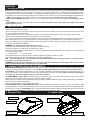
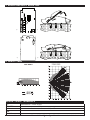
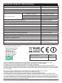
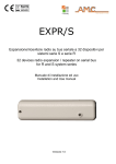
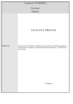
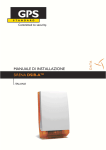
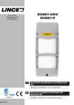
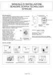
COMPLIANT
EN50131-2-4:2008
mouse
01
Sensore a doppia tecnologia - duo-mask
Installazione
installation
Dual Technology intrusion detector - duo-mask
Italiano
1. Introduzione
MOUSE 01 è un sensore a doppia tecnologia gestito da microprocessore, la sezione infrarosso è costituita da un PIR
a due elementi, la sezione a microonda è realizzata con cavità planare da 10.5 GHz. Grazie all’utilizzo di un algoritmo di calcolo del processore è in grado di soddisfare una copertura in lunghezza di 14 m e in larghezza di oltre 90°,
garantendo un’assoluta sicurezza contro i falsi allarmi. La possibilità di scegliere diversi valori in frequenza fanno del
MOUSE 01 un sensore assoluamente affidabile per qualsiasi installazione, incluso la possibilità di posizionare più
sensori in uno stesso locale senza problemi di interferenze causate dall’uso di una singola frequenza. E’ dotato di un
regolatore di portata con il quale è possibile settare la sensibilità da 3 a 14 m. MOUSE 01 può essere impiegato in tre
differenti configurazioni:
➣AND: il sensore dà allarme quando entrambe le tecnologie vengono violate (elevata immunità da falsi allarmi.)
➣OR con protezione DUOMASK: il sensore dà allarme quando una delle due tecnologie viene violata
DUO-MASK*: verifica e segnalazione di allarme anche in caso di inibizione totale di una delle due tecnologie
(es. mascheramento o rottura ecc.).
2. Installazione
- Utilizzando uno strumento sottile (esempio mini cacciavite a taglio), spingere il tastino tondo sul lato anteriore del
sensore e aprire la cover.
- rimuovere la scheda elettronica dal fondo della cover facendo leva sulla clips lato morsetti
- forare gli sfondabili che si desidera utilizzare per il fissaggio, oppure utilizzare l’apposito snodo (opzionale)
- fare scorrere il cavo di collegamento attraverso l’apposita guida sul retro della cover facendolo uscire dal foro in alto.
- cablare il circuito seguendo la guida ai collegamenti .
Se si desidera utilizzare la protezione antistrappo praticare un foro di diametro superiore a quello del tassello che verrà
utilizzato per tale protezione sul fondo del coperchio in corrispondenza dello sfondabile centrale (Fare riferimento allo
schema di foratura allegato). Inserire il tassello nel muro ed avvitare la vite lasciando fuori quanto basta per garantire
la chiusura del microinterruttore posto sul retro della scheda elettronica e rimuovere il jumper DISABLE TAMPER.
Nota: L’altezza da terra consigliata per il fissaggio è di 2m.
Verificare che tutti i DIP-Switch siano abbassati (OFF) - Scollegare il morsetto B/S.
Fornire tensione al sensore e aspettare che il led smetta di lampeggiare.
Ruotare il trimmer della regolazione portata in modo che il sensore a microonda rilevi i movimenti alla massima distanza necessaria (accensione del led in colore verde o rosso). “+” ⇒ maggiore portata “-” ⇒ minore portata
Chiudere il sensore e controllare la copertura in funzionamento AND (accensione del led in colore rosso). Riaprire il
sensore per eseguire le successive regolazioni.
Nota : Per evitare falsi allarmi si consiglia di aumentare la portata non oltre quanto effettivamente necessario.
ATTENZIONE: Installando il rivelatore ad angolo o a bandiera e disabilitanto il dispositivo antirimozione l’apparecchiatura risulta declassata al I° Livello di Prestazione (CEI 79-2).
3. Collegamento e regolazione
BLOCCO MICROONDA: (dip 1 in ON) Abilitando questa funzione, l’emissione delle microonde verrà automaticamente bloccata con impianto disinserito (ovvero quando al morsetto B/S viene fornita una tensione di +12Vdc rispetto al
negativo di alimentazione).Nota : lo spegnimento della microonda blocca il funzionamento del dispositivo antimascheramento.
BLOCCO LED: Il blocco del led è attivo quando viene fornita una tensione positiva (+12Vdc) al morsetto B/S ad impianto spento. Lasciare il morsetto B/S scollegato oppure collegarlo a negativo se non si desidera il blocco
Nota: il B/S non agisce sul relè di allarme che rimane sempre abilitato al funzionamento.
MEMORIA DI ALLARME: (dip 2 in ON) La memoria di allarme, è automaticamente attivata ad impianto disatttivato
ed è segnalata dal lampeggio lento del led (1Hz) con la seguente corrispondenza : rosso allarme completo (microonda
e infrarosso, funzionamento AND) verde allarme microonda (solo in funzionamento OR) arancione allarme infrarosso
(solo in funzionamento OR). Il reset della memoria è automaticamente eseguito subito dopo il successivo inserimento
dell’impianto.
FUNZIONE OR - DUOMASK: (dip 3 in ON) Il sensore Mouse01 è provvisto di un dispositivo in grado di rilevare un
mascheramento delle microonde atto a diminuirne la sensibilità. Per tutto il tempo in cui è presente questa particolare
manomissione, il contatto ACC di tipo N.C. si aprirà e contemporaneamente il LED del sensore lampeggerà velocemente con colore rosso. DUO-MASK: è una speciale funzione che permette di capire quando l’infrarosso viene mascherato. Per attivare il DUO-MASK è necessario configurare il DIP 3 in ON .
www.amcelettronica.com
Mouse 01 Dual Technology - Rev. 1.2
1
installation instructions
English
1. Introduction
MOUSE 01 is a digital dual technology detector. It combines a dual element PIR and a 10.5 GHz-MW detector. Owing
to its special algorithm it is able to reach a coverage of 14 m and an angle of 90° , ensuring an outstanding immunity
to false alarms. It also allows the installer to choose among different frequency values, enabling the installation of several detectors in the same premise, without any interference.The detector can work with three different configurations:
➣AND: alarm is triggered only when detection is from both technology (maximum false alarm immunity)
➣OR with DUO-MASK protection: as soon as one technology detects, the alarm is triggered (for maximum sensitivity)
➣DUO-MASK*: OR-type operation with notification of total inhibition of one of the two technologies (after masking or tampering, etc.).
2. INSTALLATION
- By using a thin screwdriver, push the round tooth on the bottom and open the housing
- Remove the PCB from the base
- Use a screwdriver to pierce the knockouts on the side of the base where you wish to attach the detector to the wall
or use the optional swivel bracket
- Route the wires via the rear channel into the base and let them pass through the hole on the top of the housing
- Wire up the terminals following the connections shown in the figure
If you want to use the Back Tamper protection practice a hole of diameter bigger than the rawlplug you will use on the
back of the detector’s cover in correspondence of the central knok-out (Please refer to the provided drill scheme).
Insert the rawlplug into the wall leaving the screw a little outside to ensure the back switch’s contact closure and remove the jumper DISABLE TAMPER.
REMARK: the advised height from the floor is 2 m
Verify that all DIPswitches are OFF and disconnect terminal B/S.
Supply the detector and wait until the LED stops to flash.
Turn the trimmer to adjust the MW range, so as to let the MW detect the movements at the distance you need (lighting
of the red or green LED):
“+” ⇨ larger range “-” ⇨ smaller range
Close the detector and check the range in AND configuration (lighting of the red LED).
Open again the detector and continue with the following adjustements.
N.B. : To avoid false alarms, it is advised to start the regulation from the minimum position ( - ) and to increase
the range not more than necessary.
WARNING: By installing the detector at the corner or flag and disabling the Back-tamper device the product
will be downgraded to the I° Performance Level (CEI 79-2).
3. Connections and adjustments
MICROWAVE INHIBITION (dip 1 ON): If this function is active, the MW emission is automatically blocked when the
control unit is disarmed (B/S is applied + 12 Vdc) Note: stopping the MW detector disable the anti-mask device.
LED BLOCK: The LED is disabled when +12 Vdc voltage is applied to terminal B/S. Apply this voltage when the control unit is disarmed . B/S is therefore used to notify the detector the control unit status. Note: activation of B/S does
not influence the alarm contact, which is in any case enabled.
ALARM MEMORY: (dip 2 ON) The alarm memory is activated when the control unit is disarmed and can be distinguished by the slow flash of the LED (1 Hz) with the following mode:
RED: alarm from both technologies (MW and PIR, in AND); GREEN: MW alarm (only in OR configuration); ORANGE:
PIR alarm (only in OR configuration).
Memory reset is carried out by arming the system.
OR CONFIGURATION - DUO-MASK (dip3 ON): Detector Mouse01 implements a device, which can detect a MW
masking attempt. For the time of this tampering, the NC ACC contact is opened and at the same time the LED flashes
quickly with a red colour. DUO-MASK: this is a special feature that enables to detect masking attempts of the PIR section. To activate DUO-MASK configuration it is necessary to set dip 3 to ON .
1. General View
Led WALK TEST
2. Inside View
Sfondabili per fissaggio
Mounting knockouts
Lente / Lens
Premere qui per aprire
Press here to open
www.amcelettronica.com
Mouse 01 Dual Technology - Rev. 1.2
2
Fissaggio circuito
Clip for electronic board
installation instructions
3. BOARD AND WALL MOUNTING
a)
b)
c)
d)
4. Lente / lens
morsettiera / TERMINALS
Alimentazione / Power Supply
-+
Protezione antiapertura / Tamper ontact (opening)
TAMPER
Contatto allarme / Alarm Contact
N.C.
Comando led walk test / Block walk test LED
B/S
Contatto antimascheramento / Antimasking Contact
MASK
Mouse 01 Dual Technology - Rev. 1.2
www.amcelettronica.com
3
installation instructions
Specifiche tecniche / specifications
Alimentazione / Input Voltage
Consumo / Current Drain (Alarm/Stand-By)
9 to 15 Vdc
(26 mA/18.5 mA) @ 13.8 Vdc
Portata in lunghezza / Coverage
14 m
Portata in larghezza / Angle
90°
Piroelettrico / PIR
Frequenza / Frequency
Microonda / Microwave
2 elementi / 2 elements
Riferimento / Reference:
10.500 GHz
R - Rosso / Red
10.550 GHz
M - Mista / Mixed
10.600 GHz
A - Azzurro / Light Blue
Lente (fasci e livelli) / Lens (beams and levels)
Segnale emesso / Signal emitted
Durata allarme / Alarm period
Tipo allarme / Alarm Type
29 patterns on 5 levels
1 mW impulsato / pulsed
4 sec.
AND - OR
Antiapertura / Anti-opening
Antistrisciamento / Creep zone
✔
✔
Contatto di allarme / Alarm Contact
Contatto di tamper / Tamper switch
Temperatura di esercizio / Operating Temperature
100 mA - 40 V - 16 Ω
Max 40 mA - 30 Vdc
From -10 °C to +55 °C
Temperatura di stoccaggio / Storage Temperature
From -20 °C to +60 °C
RFI Protezione / Protection
Led WALK TEST (MW and PIR)
Cover / Housing
10 V / m (80 /2000 MHz)
✔
ABS
Accessori / Accessories
Snodo orientabile / Swivel bracket /
Rotule orientable *
110 x 60 x 46 mm
Dimensioni / Dimensions
*: Non conforme alla Norma EN 50131-2-4
Not Compliant to the EN 50131-2-4
Meets the requirements:
Conforme ai requisiti:
R&TTE 99/5/CE
EN 50131-2-4: 2008
EN 50131-2-4 Grade 2
EN 50131-2-4 Class 2
CEI 79-2: II° Level
Countries where the frequency is implemented:
Nazioni in cui si intende l’uso:
Restrictions:
Restrizioni:
BE - BG - CY - DK - GR - IS - IT - LV - LI
LT - MT - NL - NO - PL - PT - RO - SI - CH
FR - HU - IE
LU - ES - GE
Prodotto conforme alla Direttiva 99/5/CE. La dichiarazione di conformità è disponibile presso la nostra sede.
Tutti i ns. prodotti sono conformi ai requisiti richiesti dalla norma CEI 79-2 2°ed. 1998 + Ab 2000.
L’installazione deve essere eseguita a regola d’arte da personale specializzato.
Il produttore declina ogni responsabilità nel caso in cui il prodotto venga manomesso da persone non autorizzate.
Si raccomanda di verificare il corretto funzionamento del sistema d’allarme almeno una volta al mese, tuttavia un sistema
di allarme elettronico affidabile non evita intrusioni, rapine, incendi o altro, ma si limita a diminuire il rischio che tali situazioni si verifichino.
This product comply the 99/5/CE directive. The declaration of conformity is available at our offices.
Our products/systems comply with the essential requirements of EEC directives.
Installation must be carried out following the local installation norms by qualified personnel.
The manufacturer refuses any responsibility when changes or unauthorized repairs are made to the product/system.
It is recommended to test the operation of the alarm product/system at least once a month. Despite frequent testing and
due to, but not limited to, any or all of the following: tampering, electrical or communication disruption or improper use, it
is possible for the product/system to fail to prevent burglary, rubbery, fire or otherwise. A properly installed and maintained
alarm system can only reduce the risk that this happens.
www.amcelettronica.com
Mouse 01 Dual Technology - Rev. 1.2
4
installation instructions