1
PACK CONTENT
FE SERIES
• 1 MD Operating Manual
• ST82 knob regulation accessory for the
models with sensitivity adjustment
• N° 1 mounting bracket + N° 2 screws with
bolts and washers
• N° 2 mounting brackets + N° 4 screws with
bolts and washers, only for FERHD / ** - **
• N° 1 RL122 reflector,
only for FERN / **-**
INSTALLATION MANUAL
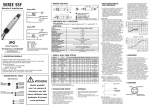
Setting object detection: remove the object; the orange LED (output) must change (position A=Max.). If not, turn the >SENS.< control knob (range 5 rotations) in the direction of
Min. until the orange LED (output) changes (e.g. position A). Set the knob to Min. Position
the object and turn the knob to Max. until the green LED lights up (e.g. position B). If
position B<position A, select middle position (e.g. position C). Check overall function. If
function is o.k. the setting procedure is over. If the setting is not o.k. check the operating
conditions and re-adjust.
If position A ≤ position B, background influence is too great. Check the operating
conditions and re-adjust.
Wiring diagrams M8 plug versions
Direct scanning, polarization, receiver
Emitter
OUT
(+)
(-)
(+)
(-)
TECHNICAL SPECIFICATIONS
GENERAL DESCRIPTION
• Miniature Photoelectric Switch series with
large scannino ranges
• Small dimensions: 20x11x31mm
plastic housing
• 90° optic axis orientation
• PNP 0r NPN output
• Lon/Don selectable output
• Trimmer adjustement
• IP67 Protection
• Red ligth emission
• Approvals
• Through-beam 15 m range
• Photoelectric reflex with polarizing
filter 6 m range
• Diffuse energetic scanner
900 mm scanning distance
• Proximity switch with
background suppression and adjustable
scanning distance up to 500 mm
M.D. Micro Detectors S.p.A.
Strada S. Caterina, 235 - 41100 Modena Italy
Tel. +39 059 420411 Fax +39 059 253973
www.microdetectors.com
[email protected]
Declaration of conformity
M.D. Micro Detectors S.p.A.
Declare under our sole responsibility that
these products are in conformity with the
following EEC directive: 89/336 and 73/23
and emendment.
Models
Type
Sensing distance
Blind zone
Hysteresis
Scanning distancesensitivity adjustment
Light source
Spot diameter
Ligtht on-Dark on select.
Supply voltage
Ripple
No load supply current
Load current max
Output voltage drop
Output type
Switching frequency
Response time
Time delay before availability
Supply electrical protections
Output electrical protections
Operation temperature range
Storage temperature
Temperature drift
FERW/0*-0*
FER8/0*-0*
FERN/0*-0*
FERD/0*-0*
FERH/00-0*
Background supp.
15 ÷ 500 mm(1)
2 mm
-
Energetic scan.
800 mm (1)
0
20% max
Reflex polariz
5 m (2)
10 mm
-
Receiver
12 m
0
-
Emitter
12 m
0
-
Potentiometer 270
Red visibile LED
250mm @ 2,5m
Turning commutator
10 ÷ 30 VCC Max
≤10% Included
30 mA max
30 mA max
20 mA max
100 mA
1,8 V max @ 100 mA
PNP or NPN open collector
1000 HZ With light/dark ratio 1:1
≤0,5 ms With resistite load
100 ms max
Overvoltage pulses and polarity reversal
Short circuit, overcurrent, overvoltage
-25 ÷ +55 °C
-40 ÷ +70 °C
±15% of scanning distance
50mm @ 300mm
30 mA max
Ambient light immunity
10 000 Lux minimum sunlight
3000 Lux minimum HF lamp
CODE DESCRIPTION
1
miniature cubic photoelectric switch
20x11x31mm
2
3
/ 4
5 - 6
FE
Housing material
Cable PVC 2m
Weight
7
A
Cable output
F
3 pin M8 connector
0
Background suppression 500mm Max
W
Energetic diffuse scanner 900mm Max
8
Reflex with polarizing filter 6m
N
Emitter 15m Max
H
Receiver 15m Max
D
0
LON/DON selectable
Plastic housing
P
PNP logic output
N
NPN logic output
O
Emitter
Min.
Yellow: output status;
Green: operative reserve> 1,1
-
PBT housing; PC Optics
3x0,18 ø 4mm
53 g cable version; 9 g Plug version
C
Max.
2x0,18 ø 4mm
A
(1) White target 90% 100x100 mm
(2) With RL110 reflector
• Make sure that the supply voltage is correctly settled with a ripple corresponding
to the values indicated on the catalogue.
• To extend the supply and output cables, it is necessary to use a cable having
conductors with a minimum size of 1 mm2. The maximum length of extension is
100m (this value is referred to a minimum tension and power supply at a load of
100mA).
• Avoid the deposit of dust, water, moisture, etc. on the optic surface; this kind of
deposits could compromise the reading features of the device.
• Protect the optic against organic solvents.
ELECTRIC DIAGRAMS OF THE CONNECTIONS
• Avoid direct exposure of the receiver to intense light sources or sun light.
Wiring diagrams cable versions
NPN output
1 Bn
+10-30 VDC
1 Bn
100 mA
load
+10-30 VDC
Alignment and adjustment
100 mA
load
4 Bk
3 Bu
• Clean the optic with a wet cloth and then dry it.
PNP output
4 Bk
0V
0V
3 Bu
Emitter
1 Bn
+10-30
VDC
1/Bn : Brown
3/Bu : Blue
4/Bk : Black
4 Bk
3 Bu
CODE DESCRIPTION
0V
Direct proximity scanner models
Mount the unit using the suggested brackets (supplied) and connect and align the sensor following the connection diagrams.
Select operating mode:
L: Light-switching; if light received, output switches.
D: dark-switching, if light interrupted, output switches
Place the object to be detected at the required reading distance, checking that the optic
axis is perpendicular to the object surface.
NOTE: In case of reflecting or flat objects, it could be convenient to recline the sensor of
some degrees with respect to the perpendicular.
Adjust the light reception:
LED grn(=green): light reception with function reserve >1.1
LED ora(=orange): switching output active. Set the >SENS.< control knob to max., place
the object and determine switch-on and switch-off points of the orange LED by moving
the light beam horizontally and vertically. Select middle position. At optimum reception,
the green LED lights up. If the orange LED does not change, too little or no light at all is
being received. In this case, re-adjust or clean the light sensor.
Setting object detection: remove the object; the orange LED (output) must change (position A=Max.). If not, turn the >SENS.< control knob (range 5 rotations) in the direction of
Min. until the orange LED (output) changes (e.g. position A). Set the knob to Min. Position
the object and set the knob in direction Max. until the green LED lights up (e.g. position
B). If position B<position A, select middle position (e.g. position C).
Check overall function. If function is o.k. the setting procedure is
over. If the setting is not o.k. check the operating conditions and readjust.
If position A ≤ position B, background influence too great. Check the
operating conditions and re-adjust.
B
-
• In case the noise produced by the power lines exceed the values foreseen by the
CE norm (interference immunity), separate the sensor cables from both the power
and high tension lines, and insert it in a grounding metal raceway. Moreover, it is
advisable to connect the sensor directly to the supply source and not to other
devices.
HD
Emitter+Receiver 15m Max
-
CONNECTIONS AND INSTALLATION
R
Visibile red emission LED
15 mA max
-
IP 67
Enclosure rating
LED indicators
1600mm @ 12m
-
MECHANICAL DRAWINGS
Direct proximity scanner with background suppression
Mount the unit using the suitable brackets (supplied), connect and align the sensor
following the connection diagrams.
Select operating mode:
L: Light-switching; if light is received, output switches.
D: dark-switching, if light is interrupted, output switches.
Place the object to be detected at the required reading distance, checking that the
optic axis is perpendicular to the object surface.
NOTE: In case of reflecting or flat objects, it could be convenient to recline the sensor
of some degrees with respect to the perpendicular.
Adjust the light reception:
LED grn(=green): light reception with function reserve >1.1
LED ora(=orange): switching output active. Set the >SENS.< control knob to max.,
place the object and determine switch-on and switch-off points
of the orange LED by moving the light beam horizontally and vertically. Select middle position. At optimum reception, the green
LED lights up. If the orange LED does not change, too little or no
light at all is being received. In this case, re-adjust or clean the
light sensor and check the operating conditions.
Photoelectric reflex switch, with reflector models
Mount the reflector so that its surface is perpendicular to the optic axis. Check that the
distance between the sensor and the reflector does not exceed the values specified for
the reflector itself. Fix the sensor safely but not permanently and select the output type.
For a perfect alignment , follow the procedure below.
Adjust te light reception:
LED grn(=green): light reception with function reserve >1.1
LED ora(=orange): switching output active. Set the >SENS.< control knob to max., determine switch-on and switch-off points of the orange LED by moving the light beam horizontally and vertically. Select middle position so as the red light beam strikes the center
of the reflector. At optimum reception, the green LED lights up. If the orange LED does
not change, too little or no light at all is being received. In this case, re-adjust photoelectric switch and reflector and, eventually, clean them.
Emitter – Receiver models
Select operating mode:
L: Light-switching; if light received, output switches.
D: dark-switching, if light interrupted, output switches
Mount Emitter and Reciver using the fixing holes to the holder (supplied) opposite to the
reflector and align roughly. Keep into consideration the reception capability of the light
beam. Power the device. The emission led of the emitter lights up.
Adjust te light reception:
LED grn(=green): light reception with function reserve >1.1
LED ora(=orange): switching output active. Set the >SENS.< control knob to max., determine switch-on and switch-off points of the orange LED of the receiver by moving the
light beam horizontally and vertically. Select middle position so as the red light beam
strikes the receiver. At optimum reception, the green LED lights up. If the orange LED
does not change, too little or no light at all is being received. In this case, re-adjust emitter and receiver and, eventually, clean them.
Setting object detection:
Place object in light beam. The orange LED must change. If not, reduce the sensitivity
using the >SENS.< control knob until the orange LED changes. When the object is removed, the green LED must light up again. If this is not the case, adjust the sensitivity until
the switching threshold is correctly set. If the green LED does not go out when an object
is present, the light reception is too low (e.g. object too small, object transparent).
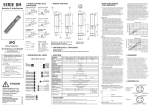
FERW/**_*A
1
2
3
4
5
6
7
8
Sensitivity area
MBx1 connector output
Output satus led
Signal limit led
Sensitivity adjustment trimmer
Output status selectable trimmer
RL122 (FE polarizing filter)
STFE OO (FE bracket)
1
2
3
4
5
6
Sensitivity area
MBx1connector output
Output satus led
Signal limit led
Sensitivity adjustment trimmer
Output status selectable trimmer
B
WARNING These products are NOT safety sensors and
are NOT suitable for use in personal safety
application
Min.
C
Max.
A