1
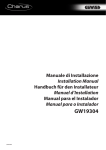
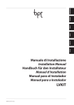
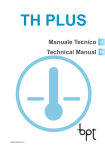
AZV/PSI
Manuale di Installazione
Installation Manual
24802640 – 21-01-11
IT - Avvertenze generali
EN - General Precautions
• Leggere attentamente le istruzioni, prima di iniziare l’installazione ed eseguire gli interventi come specificato dal costruttore;
• Dopo aver tolto l’imballaggio assicurarsi dell’integrità dell’apparecchio;
• Gli elementi dell’imballaggio (sacchetti in plastica, polistirolo espanso, ecc.) non devono essere lasciati alla portata dei bambini
in quanto potenziali fonti di pericolo;
• L’installazione, la programmazione, la messa in servizio e la manutenzione del prodotto deve essere effettuata soltanto
da personale tecnico qualificato ed opportunamente addestrato nel rispetto delle normative vigenti ivi comprese le
osservanze sulla prevenzione infortuni;
• Operare in ambienti sufficientemente illuminati e idonei per la salute e utilizzare strumenti, utensili ed attrezzature in
buono stato;
• Il dispositivo è adatto all’installazione da interno, esclusivamente in luoghi asciutti e non polverosi;
• Non ostruire le aperture o fessure di ventilazione o di smaltimento di calore;
• L’impianto elettrico dovrà essere realizzato in conformità con le normative in vigore nel paese di installazione;
• Prima di collegare le apparecchiature alimentate a tensione di rete accertarsi che i dati di targa siano rispondenti a quelli
della rete di distribuzione;
• Proteggere le apparecchiature alimentate a tensione di rete con un interruttore di rete onnipolare con una separazione
dei contatti di almeno 3 mm;
• I conduttori dei cablaggi non utilizzati devono essere isolati.
• Per prevenire contatti accidentali, fascettare separatemente i cavi di collegamento alla rete e quelli dei segnali in bassissima tensione.
• Le schede elettroniche possono essere seriamente danneggiate dalle scariche elettrostatiche: qualora vi sia bisogno di
maneggiarle indossare idonei indumenti e calzature antistatiche o, almeno, assicurarsi preventivamente di aver rimosso
ogni carica residua toccando con la punta delle dita una superficie metallica connessa all’impianto di terra (es. lo chassis
di un elettrodomestico);
• Saldare le giunzioni e la parte terminale dei fili onde evitare malfunzionamenti causati dall’ossidazione degli stessi;
• Al termine dell’installazione, verificare sempre il corretto funzionamento dell’apparecchiatura e dell’impianto nel suo
insieme;
• Prima di effettuare qualunque operazione di pulizia o di manutenzione, togliere l’alimentazione al dispositivo; nel caso di
apparecchiature alimentate a tensione di rete togliere l’alimentazione, aprendo l’interruttore posto a monte dello stesso;
• In caso di guasto e/o cattivo funzionamento di un dispositivo, distaccarlo dall’alimentazione e non manometterlo;
• Per l’eventuale riparazione rivolgersi solamente ad un centro di assistenza tecnica autorizzato dal costruttore e comunque utilizzare sempre i ricambi forniti da Bpt s.p.a.;
L’apparecchio dovrà essere destinato unicamente all’uso per il quale è stato espressamente concepito.
Il mancato rispetto delle prescrizioni sopra elencate può compromettere la sicurezza dell’apparecchio.
Il costruttore non può comunque essere considerato responsabile per eventuali danni derivanti da usi impropri,
erronei ed irragionevoli.
SMALTIMENTO
Assicurarsi che il materiale d’imballaggio non venga disperso nell’ambiente, ma smaltito seguendo le norme vigenti nel
paese di utilizzo del prodotto.
Alla fine del ciclo di vita dell’apparecchio evitare che lo stesso venga disperso nell’ambiente. Lo smaltimento dell’apparecchiatura deve essere effettuato rispettando le norme vigenti e privilegiando il riciclaggio delle sue parti costituenti. Sui
componenti, per cui è previsto lo smaltimento con riciclaggio, sono riportati il simbolo e la sigla del materiale.
IT - INSTALLAZIONE
• L’alimentatore deve essere installato SEMPRE in orizzontale.
• L’apparecchio è installabile su guida DIN (EN 50022) in un apposito quadro elettrico.
• Per le dimensioni di ingombro vedere la figura 1.
NOTA. Provvedere ad una corretta areazione nel caso l’alimentatore venga
installato in un contenitore metallico.
• Read the instructions carefully before starting installation and proceed as specified by the manufacturer;
• After removing the packaging, check the condition of the unit;
• The packaging items (plastic bags, expanded polystyrene, etc.) must not be handled by children as they may be dangerous;
• Installation, programming, commissioning and maintenance of the product must only be performed by qualified technicians who have been properly trained in compliance with current standards, including health and safety regulations;
• Operate in sufficiently lighted areas that are conducive to health and use tools, utensils and equipment that are in good
working order;
• The device is suitable for indoor installation, exclusively in dry and non-dusty areas;
• Do not obstruct the openings or slots used for ventilation or heat disposal;
• The electrical system must comply with current standards in the country of installation;
• Before connecting the equipment powered by mains voltage, make sure that the rating plate data corresponds to that of
the distribution network;
• Protect the equipment powered by mains voltage with an omnipolar switch with contacts separated by at least 3 mm;
• Wires belonging tocables that are not used must beinsulated.
• To prevent accidental contacts, clamp the network connection cables and the very low voltage signal cables separately.
• The electronic cards can be seriously damaged by discharges of static electricity: if they are to be handled, wear suitable
clothing and anti-static footwear, or at least, ensure static electricity has been discharged by touching with the fingertip
a metallic surface connected to the earth system (e.g. the chassis of a household appliance);
• Weld the joints and the ends of the wires to prevent malfunctions caused by wire oxidation;
• Upon completion of installation, always check for correct operation of the unit and the system as a whole;
• The installer must make sure that the information for the user, where applicable, is present and is delivered;
• Before performing any cleaning or maintenance operation, disconnect the power supply to the device; if the equipment
is powered by mains voltage disconnect the power supply, opening the switch located upstream of it;
• In the case of device failure or malfunction, disconnect it from the power supply and do not tamper with it;
• Should the unit be in need of repair, contact only a technical support centre authorised by the manufacturer and always
use spare parts provided by Bpt s.p.a.;
The equipment must only be used for the purpose for which it was explicitly designed.
Failure to follow the instructions provided above may compromise the unit’s safety.
The manufacturer declines all liability for any damage as a result of improper, incorrect or unreasonable use.
DISPOSAL
Do not litter the environment with packaging material: make sure it is disposed of according to the regulations in force
in the country where the product is used.
When the equipment reaches the end of its life cycle, avoid discarding in the environment. The equipment must be
disposed of in compliance with current regulations, recycling its component parts wherever possible. Components that
qualify as recyclable waste feature the relevant symbol and material acronym.
EN - INSTALLATION
• The power supplier must ALWAYS be installed horizontally.
• The device can be installed on a DIN rail (EN 50022) in an appropriate electric
panel.
• For the overall dimensions see figure 1.
NOTE. Proper ventilation is required if the power supplier is installed in a
metal container.
4545
106
106
A
A
43,5
43,5
7,5
57
7,5
57
105
105
145
145
B
B
fig. 1
2
105
105
64,5
64,5
fig. 2
PRG.
IT
- MORSETTIERE
EN
Rete
M1
SW2
M1
SW1
SW2
BIN
MIC. ADJ.
+
M1
Alimentazione 18VDC
A
BOUT BUS line output
–
+
Power supply 18VDC
Audio posto esterno
A
Audio Entry panel
–
Uscita –
–
Output –
V
Video posto esterno
V
Video Entry panel
+
Uscita +
+
Output +
BIN
- FUNZIONE DEI JUMPER E REGOLAZIONI
EN
Estrarre il jumper per entrare in modalità programmazione
Estrarre il jumper per almeno 5” per cancellare la programmazione
Regolazione volume microfono HEVC/MI
y I volumi dei dispositivi vengono tarati in fabbrica; agire sulle regola-
- CARATTERISTICHE TECNICHE
I
Potenza dissipata
Uscita alimentazione
Temperature di stoccaggio
Temperature di funzionamento
Grado IP
max
=200 mAAC
AC
10W max
18 VDC, 1A - 0,5A 1’/3’
-25 °C + 70 °C
0 °C +35 °C
30
Remove the jumper to access the programming mode
Remove the jumper for 5 seconds to delete the programming
HEVC/MI microphone volume adjustment
y The volumes of the devices are calibrated at the factory; act on the
adjustments only if necessary
EN
230 VAC 50÷60 Hz
Alimentazione
Corrente assorbita
- JUMPER FUNCTION AND ADJUSTMENTS
SW1
SW2
MIC.
ADJ.
zioni solo se strettamente necessario
IT
–
+
BUS line input
M2
+ V – A + – BOUT
SW1
SW2
MIC.
ADJ.
BOUT Uscita linea BUS
M2
–
Mains
BIN
Ingresso linea BUS
M2
SW1
PRG. DEL. MEM.
IT
- TERMINAL BOARDS
DEL. MEM.
- TECHNICAL FEATURES
230 VAC 50÷60 Hz
Power supply
Input current
I
max
=200 mAAC
AC
10W max
18 VDC, 1A - 0,5A 1’/3’
-25 °C + 70 °C
0 °C +35 °C
30
Dissipated power
Power supply output
Storage temperature
Operating temperature
IP Degree
IT - PROGRAMMAZIONE – EN - PROGRAMMAZIONE
1
IT - Sull’ AZV/PSI
Estrarre il jumper SW1
per entrare in modalità
programmazione.
EN - On the AZV/PSI
Remove the SW1
jumper to access the
programming mode.
2
IT - Sul derivato interno
Sollevare la cornetta (se
presente) e premere
contemporaneamente
per 2 secondi i pulsanti
apriporta e ausiliario
(:); su derivati della
linea Mitho premere
il pulsante “prog.
manuale”; si attivano
l’audio e il video (se
presente), verso il posto
esterno.
EN - On the receiver
Raise the handset (if
present) and press both
door lock release and
auxiliary buttons at the
same time, for 2 seconds (:);
with receivers which form
part of the Mitho interface,
press the button “manual
prog.”; audio and video (if
present) will activate on the
entry panel.
IT - Sul posto esterno
premere il pulsante di
chiamata al quale si
vuole associare il derivato
interno (beep lungo di
conferma); ripetere le
operazioni descritte ai
punti 2 e 3 su eventuali
altri derivati interni.
EN - On the entry panel
press the call button to
which the receiver wishes
to establish a connection
(extended beep sound acts
as confirmation); repeat
the operations described
in points 2 and 3 on any
subsequent receivers.
4
IT - Sull’ AZV/PSI
Reinserire il ponticello
SW1 per uscire
dalla modalità
programmazione.
EN - On the AZV/PSI
Re-insert the SW1 jumper
to exit the programming
mode.
SW1
3
SW1
3
IT - CONFIGURAZIONE BASE
HEVC/301 MI
AZV/PSI
EN - BASIC CONFIGURATION
MITHO
MAX. 15mt
MAX. 3mt
Alla montante
To the riser
AZV/PSI
MITHO
M1
BIN
RETE
MAINS
M1
M2
AL
+
-
B
BOUT
–
+
A
–
V
+
M2
SW4
MM
HEVC/301 MI
A
B
IT - CONFIGURAZIONE CON DUE
DERIVATI INTERNI
AZV/PSI
HEVC/301 MI
OPHERA
MITHO
MAX. 15mt
EN - TWO RECEIVER
CONFIGURATION
MAX. 3mt
VAS/101
Alla montante
To the riser
AZV/PSI
M1
BIN
MITHO
RETE
MAINS
M1
M2
AL
+
-
B
BOUT
–
+
A
–
V
+
M2
SW4
MM
VAS/101
HEVC/301 MI
RETE
MAINS
A
M1
M2
+
–
OPHERA - (OPHERA/B)
M1
B
+
-
SW2
BUS
AL
SW1
LOCAL
B
4
IT - CONFIGURAZIONE CON DUE
POSTI ESTERNI DI PIANO
HEVC/301 MI
AZV/PSI
MITHO
MAX. 15mt
EN - TWO ENTRY PANEL PER
FLOOR CONFIGURATION
MAX. 3mt
HEVC/301 MI
AZV/PSI
MAX. 15mt
MAX. 3mt
AZV/PSI
M1
BIN
Alla montante
To the riser
MITHO
M1
RETE
MAINS
M2
AL
+
-
B
BOUT
–
+
A
–
V
+
M2
SW4
MM
HEVC/301 MI
A
AZV/PSI
M1
BIN
RETE
MAINS
M2
BOUT
–
+
A
–
V
+
HEVC/301 MI
A
B
BIN
BOUT
–
+
A
–
V
+
A
M2
Cat. 5
Rosso
Red
Blu
Blue
A
–
V
+
Giallo
Yellow
Bianco
White
5
IT - CONFIGURAZIONE CON UN
POSTO ESTERNO DI PIANO ED
UNA TELECAMERA
HEVC/301 MI
AZV/PSI
MITHO
MAX. 15mt
EN - ONE ENTRY PANEL
AND CAMERA PER FLOOR
CONFIGURATION
MAX. 3mt
AZV/PSI
MAX. 15mt
Alla montante
To the riser
AZV/PSI
M1
BIN
MITHO
M1
RETE
MAINS
M2
AL
+
-
B
BOUT
–
+
A
–
V
+
M2
SW4
MM
HEVC/301 MI
A
AZV/PSI
M1
BIN
RETE
MAINS
M2
BOUT
–
+
A
–
V
+
Camera
V
–
B
BIN
BOUT
–
+
A
–
V
+
A
6
M2
Cat. 5
Rosso
Red
Blu
Blue
A
–
V
+
Giallo
Yellow
Bianco
White
IT - FUNZIONALITÀ DELL’IMPIANTO
EN - PLANT FEATURE
• Avviso di chiamata.
Se, nel corso di una comunicazione, il derivato interno viene chiamato da altri posti
esterni o dal portiere, il terminale emette un tono di avviso; qualora si desideri rispondere alla chiamata, è sufficente chiudere la conversazione in corso (entro 30 s)
per essere messi automaticamente in comunicazione con il chiamante.
• Call waiting.
If, during a call, other entry panels or the porter contact the receiver, the terminal
will emit a warning signal; should you wish to answer the call, you must simply
end the current call (within 30 seconds) and you will be automatically connected
to the caller.
• Modalità di autoinserimento.
Premendo ripetutamente il pulsante “autoinserimento”, si potranno vedere in successione le immagini dai posti esterni di piano (1 e 2 in figura); a seguire, in sequenza
ciclica le immagini dai posti esterni principali (3, 4 e 5 in figura).
Per rivedere le immagini dai posti esterni di piano (1 e 2 in figura), sarà necessario
terminare la chiamata e quindi ripremere il pulsante “autoinserimento”.
• Self-connection mode.
By repeatedly pressing the “self-connection” button, you are able to view the images from the floor entry panels (figures 1 and 2) in succession; you are also able
to follow the images from the main entry panels in a cycle sequence (figures 3,4
and 5).
To re-view the images from the floor entry panels (figures 1 and 2), you will need
to end the call and then re-press the “self-connection” button.
2
3
1
4
5
7
IT
Eventuali aggiornamenti del presente documento sono disponibili sul sito www.bpt.it.
EN
Any updates made to this document are available at this site: www.bpt.it.
Il produttore si riserva il diritto di apportare qualsiasi modifica al prodotto al fine di migliorarne le funzionalità.
The manufacturer reserves the right to make any modification to the product in order to improve its functionality.
BPT S.p.A.
Via Cornia, 1
33079 Sesto al Reghena (PN)-Italy
http: www.bpt.it
e-mail: [email protected]