1
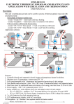
Manuale Tecnico
Technical Manual
___________________________________________
__________________________________________
IT
EN
MithoDomotici_TEC IT-EN 24800812 10-05-12
MithoDomotici_TEC IT-EN 24800812 02-05-12.indd 1
05/07/12 13.43
Manuale Tecnico – Thecnical Manual
AVVERTENZE
Le informazioni pubblicate nel presente manuale contengono diritti di Bpt S.p.a. o dei suoi fornitori e non possono essere riprodotte in
qualsiasi maniera né trasmesse ad altri.
Le informazioni contenute nel presente manuale sono soggette a modifiche senza preavviso.
Bpt S.p.a. non assume alcuna responsabilità per gli eventuali errori che il presente documento può contenere.
Nessuna parte del presente manuale può essere riprodotta in qualsiasi forma o mezzo elettronico o meccanico, per alcun uso, senza il
permesso scritto di Bpt S.p.a..
ATTENZIONE
IT
EN
•
•
•
•
•
•
•
•
•
•
•
•
•
•
•
•
•
•
•
•
Dopo aver tolto l’imballaggio assicurarsi dell’integrità dell’apparecchio.
Gli elementi dell’imballaggio (sacchetti in plastica, polistirolo espanso, ecc.) non devono essere lasciati alla portata dei bambini in quanto
potenziali fonti di pericolo.
Leggere attentamente le istruzioni, prima di iniziare l’installazione ed eseguire gli interventi come specificato dal costruttore.
Prima di collegare l’apparecchio accertarsi che i dati di targa siano rispondenti a quelli della rete di distribuzione.
A monte dell’apparecchio, sull’impianto elettrico dell’edificio, deve essere presente un interruttore di rete onnipolare con una separazione dei contatti di almeno 3 mm.
Il costruttore non può essere considerato responsabile per eventuali danni derivanti da usi impropri, erronei ed irragionevoli.
Prima di effettuare qualunque operazione di pulizia o di manutenzione, disinserire l’apparecchio dalla rete di alimentazione elettrica,
aprendo l’interruttore dell’impianto.
In caso di guasto e/o cattivo funzionamento dell’apparecchio, distaccarlo dall’alimentazione e non manometterlo.
Utilizzare sempre ricambi originali.
L’installazione, la programmazione, la messa in servizio e la manutenzione del prodotto deve essere effettuata soltanto da personale
tecnico qualificato ed opportunamente addestrato nel rispetto delle normative vigenti ivi comprese le osservanze sulla prevenzione
infortuni.
Operare in ambienti sufficientemente illuminati e idonei per la salute e utilizzare strumenti, utensili ed attrezzature in buono stato.
Al termine dell’installazione verificare sempre il corretto funzionamento dell’apparecchiatura e dell’impianto nel suo insieme.
Non installare il dispositivo all’esterno o in luoghi dove sia sottoposto a stillicidio o a spruzzi d’acqua.
Trattare con cura il dispositivo, contiene parti elettroniche fragili e sensibili all’umidità.
Le schede elettroniche possono essere seriamente danneggiate dalle scariche elettrostatiche: qualora vi sia bisogno di maneggiarle
indossare idonei indumenti e calzature anti statiche o, almeno, assicurarsi preventivamente di aver rimosso ogni carica residua toccando
con la punta delle dita una superficie metallica connessa all’impianto di terra (es. lo chassis di un elettrodomestico).
Saldare le giunzioni tra i fili onde evitare falsi allarmi causati dall’ossidazione dei fili stessi.
L’impianto elettrico dovrà essere realizzato in conformità con le normative in vigore nel paese di installazione.
Il mancato rispetto di quanto sopra può compromettere la sicurezza dell’apparecchio.
L’installatore deve assicurarsi che le informazioni per l’utente, dove previste, siano presenti sugli apparecchi.
Lo smaltimento dei componenti va eseguito secondo quanto stabilito dalle normative vigenti.
2
MithoDomotici_TEC IT-EN 24800812 02-05-12.indd 2
05/07/12 13.43
Manuale Tecnico – Thecnical Manual
WARNINGS
The information in this manual is covered by the rights of Bpt S.p.a. or its suppliers and may not be reproduced in any way, nor transmitted
to others.
The information in this manual is subject to change without advance notice.
Bpt S.p.A. shall not be held liable for any errors which this document may contain.
No part of this manual may be reproduced in any mechanical or electronic form or means, for any use, without the written permission of
Bpt S.p.a.
ATTENTION
•
•
•
•
•
•
•
•
•
•
•
•
•
•
•
•
•
•
•
•
After removing the packaging, check the condition of the unit.
The packaging items (plastic bags, expanded polystyrene, etc.) must not be handled by children as they may be dangerous.
Carefully read the instructions before starting installation. Perform work as specified by the manufacturer.
Before connecting the equipment, make sure that the rating plate data corresponds to that of the distribution network.
An omnipolar switch, with contacts separated by at least 3mm, must be installed upstream on the equipment, on the electric system of
the building.
The manufacturer declines all liability for any damage as a result of improper, incorrect or unreasonable use.
Before performing any cleaning or maintenance operation, disconnect the equipment from the power supply network by opening the
system switch.
In case of failure and/or malfunction of the device, detach it from the power supply and do not tamper with it.
Use original spare parts.
Installation, programming, commissioning and maintenance of the product must only be performed by qualified technicians who have
been properly trained in compliance with current standards including compliance with accident prevention.
Operate in sufficiently lighted areas that are conducive to health and use tools, utensils and equipment that are in good working order.
Upon completion of installation, always check for correct operation of the unit and the system as a whole.
Do not install the device outdoors or in areas where it is exposed to seepage or splashes of water.
Handle the device with care. It contains electronic parts that are fragile and sensitive to humidity.
The electronic cards can be seriously damaged by discharges of static electricity. If they are to be handled, wear suitable clothing and
anti-static footwear, or at least, ensure static electricity has been discharged by touching with the fingertip a metallic surface connected
to the earth system (e.g. the chassis of a household appliance).
Weld the joints between wires to prevent false alarms caused by oxidation of the wires.
The electrical system must comply with current standards in the country of installation.
Failure to comply with the above instructions may compromise the unit’s safety.
The installer must make sure that the information for the user, where applicable, is present on the devices.
Dispose of the unit in accordance with current standards.
IT
EN
3
MithoDomotici_TEC IT-EN 24800812 02-05-12.indd 3
05/07/12 13.43
Manuale Tecnico – Thecnical Manual
L’ARCHITETTURA DEL SISTEMA
SYSTEM ARCHITECTURE
MITHO XL
MITHO HA
ALIMENTATORE LOCALE
LOCAL POWER SUPPLIER
IT
ALIMENTATORE LOCALE
LOCAL POWER SUPPLIER
MITHO XLE
nota: sul BUS Multimaster
EN
non possono essere collegati più di 10 dispositivi
ALIMENTATORE LOCALE
LOCAL POWER SUPPLIER
note: on Multimaster BUS
not more than 10 devices can be connected
MITHO PLUS
ALIMENTATORE LOCALE
LOCAL POWER SUPPLIER
Doppino Twistato
Twisted pair
Bus Videocitofonia 2 fili X1
2-wire bus X1 video entry control system
APPARTAMENTO C
APPARTAMENT C
APPARTAMENTO B
APPARTAMENT B
DISTRIBUTORE
VIDEOCITOFONICO
VIDEO ENTRY CONTROL
DISTRIBUTOR
APPARTAMENTO D
APPARTAMENT D
Videocitofonia
Mitho plus e Mitho XL, possono essere collegati direttamente ai sistemi videocitofonici BPT con montanti a 2 o 4 fili, garantendo tutte le funzionalità
tipiche delle apparecchiature BPT, compresa la possibilità di avere più di un
monitor intercomunicante per appartamento.
UNITÀ DI SISTEMA
VIDEOCITOFONIA 2 FILI X1
2-WIRE X1 VIDEO ENTRY
CONTROL SYSTEM UNIT
POSTO ESTERNO
ENTRY PANEL
Video entry control
Mitho plus e Mitho XL, can be connected directly to BPT video entry control
system with 2 or 4 wires riser, guaranteeing all the functions typical of a BPT
video entry control appliance, including the possibility to have more than
one intercommunicating monitor per apartment.
4
MithoDomotici_TEC IT-EN 24800812 02-05-12.indd 4
05/07/12 13.43
Manuale Tecnico – Thecnical Manual
NODI DOMOTICI
HOME AUTOMATION NODES
ALIMENTATORE
AUTOMAZIONI
AUTOMATION
POWER SOURCE
Doppino Twistato
Twisted pair
Automazione Elettrica
Tramite il gateway, Mitho si interfaccia con il mondo della
domotica bpt. Attraverso un sistema a logica programmabile,
costituito da una serie di dispositivi e da un bus di campo, è
possibile gestire l’automazione elettrica (comando scenari,
comando luci, comando aperture, irrigazione, tende,...) e la
termoregolazione.
* NOTA: il cavo utilizzato è il bus BPT NH-C1D
IT
Electric Automation
Mitho interfaces with the world of BPT home automation
through the gateway. Using a programmable logic system,
comprised of a series of devices and a field bus, it is possible
to manage the electric automation (scenario control, light
control, opening control, irrigation, blinds, etc.) and heat
regulation.
EN
* NOTE: the cable used is the bus BPT NH-C1D
Bus Automazioni
Automations Bus
Bus Multimaster
Multimaster Bus
Bus Multimaster
Multimaster Bus
Bus Videocitofonia 2 fili X1
2-wire bus X1 video entry control system
Bus Automazioni
Automations Bus
ALIMENTATORE
LOCALE
GATEWAY
OH/GW
Bus Antintrusione
Anti-intrusion bus
LOCAL POWER
SUPPLIER
Alimentazione posti esterni
Entry panel power supply
Alimentazione locale
Local power supply
5 fili
5 wires
INTERFACCIA SERIALE
SERIAL INTERFACE
Sistemi compatibili
Compatible systems
Brahms B2
ALIMENTATORI
POWER SUPPLIERS
Antintrusione
Come per l’automazione elettrica, è possibile interfacciarsi con sistemi
antintrusione Brahms compatibili. In questo modo si possono gestire l’attivazione o la disattivazione totale o parziale dell’impianto d’allarme e visualizzare lo stato delle diverse zone controllate.
SIRENA
SIREN
SENSORE
SENSOR
Anti-intrusion system
As for the electric automation, it is possible to interface with compatible
anti-intrusion system Brahms. This makes it possible to manage the total
or partial activation and deactivation of the alarm system and display the
status of the various controlled zones.
5
MithoDomotici_TEC IT-EN 24800812 02-05-12.indd 5
05/07/12 13.43
Manuale Tecnico – Thecnical Manual
INSTALLAZIONE E MESSA IN SERVIZIO
INSTALLATION AND START UP
Mithoplus - Caratteristiche tecniche
Mithoplus - Thecnical features
Mithoplus è l’innovativo terminale multifunzione a colori touch
screen, pensato per la gestione e il controllo dell’automazione
elettrica HOME SAPIENS BPT, della sicurezza antintrusione Brahms
e della videocitofonia BPT negli impianti con montante a 2 o 4 fili.
L’audio viva voce e la cornetta integrata permettono una comunicazione semplice e immediata.
Mithoplus is the innovative colour touch screen multifunctional
terminal designed for the management and control of BPT HOME
SAPIENS electric automation, Brahms anti-intrusion security and
video entry control BPT in plants with a riser with 2 or 4 wire.
The hands-free audio and the integrated receiver allow simple,
immediate communications.
IT
5
1
EN
2
3
4
1 – Altoparlante (vivavoce)
Loudspeaker (hands free)
2 – Cornetta
Receiver
3 – Microfono
Microphone
4 – Display 16:9 touch screen 4,3”
4.3” touch screen 16:9 display
5 – Alloggiamento penna per touch screen
Touchscreen pen housing
Specifiche tecniche
• Display 16:9 wide screen 4,3”, 480x272 pixel, touch screen.
• Temperatura di funzionamento: da 5 °C a 40 °C.
• Alimentazione:
14÷24 V DC locale (12÷16 V AC locale).
• Assorbimento:
0,75 A (1,5 A di picco) 12 V AC – 0,5 A (1,1 A di picco) 16 V AC,
0,31 A (0,81 A di picco) 18 V DC – 0,23 A (0,58 A di picco) 24 V DC.
• Dimensioni: 203 x 108 x 31 mm.
Technical specifications
• 16:9 wide screen 4.3” 480x272 pixel touch screen display
• Operating temperature: from 5 °C to +40 °C.
• Power supply:
14÷24 Vdc local (12÷16 Vac local).
• Absorption:
0.75 A (1.5 A peak) 12 Vac – 0.5 A (1.1 A peak) 16 Vac,
0.31 A (0.81 A peak) 18 Vdc – 0.23 A (0.58 A peak) 24 Vdc
• Dimensions: 203x108x31 mm.
6
MithoDomotici_TEC IT-EN 24800812 02-05-12.indd 6
05/07/12 13.43
Manuale Tecnico – Thecnical Manual
Mithoha - Caratteristiche tecniche
Mithoha - Thecnical features
Mithoha è l’innovativo terminale multifunzione a colori touch screen, pensato per la gestione e il controllo dell’automazione elettrica
HOME SAPIENS BPT e della sicurezza antintrusione Brahms.
Mithoha is the innovative colour touch screen multifunctional
terminal designed for the management and control of BPT HOME
SAPIENS electric automation, Brahms anti-intrusion security.
IT
2
EN
A
1 – Display 16:9 touch screen 4,3”
Display 16:9 touch screen 4,3”
2 – Alloggiamento penna per touch screen
Touchscreen pen housing
Specifiche tecniche
• Display 16:9 wide screen 4.3”, 480x272 pixel, touch screen.
• Temperatura di funzionamento: da 5 °C a 40 °C.
• Alimentazione:
14÷24 V DC locale (12÷16 V AC locale).
• Assorbimento:
0,48 A a 12 V AC – 0,36 A a 16 V AC,
0,20 A a 18 V DC – 0,15 A a 24 V DC.
• Dimensioni: 163 x 106 x 31,5 mm.
Technical specifications
• 16:9 wide screen 4.3” 480x272 pixel touch screen display.
• Operating temperature: from 5 °C to +40 °C.
• Alimentazione:
14÷24 Vdc local (12÷16 Vac local).
• Absorption:
0.48 A a 12 V AC – 0.36 A a 16 V AC,
0.20 A a 18 V DC – 0.15 A a 24 V DC.
• Dimensions: 163 x 106 x 31. 5 mm.
7
MithoDomotici_TEC IT-EN 24800812 02-05-12.indd 7
05/07/12 13.43
Manuale Tecnico – Thecnical Manual
IT
Mitho XL/XLE - Caratteristiche tecniche
Mitho XL/XLE - Thecnical features
Mitho XL/XLE è l’innovativo terminale multifunzione a colori touch
screen, pensato per la gestione e il controllo dell’automazione
elettrica HOME SAPIENS BPT, della sicurezza antintrusione Brahms
e della videocitofonia BPT negli impianti con montante a 2 o 4 fili.
L’audio viva voce permette una comunicazione semplice e immediata.
Mitho XL/XLE is the innovative colour touch screen multifunctional
terminal designed for the management and control of BPT HOME
SAPIENS electric automation, Brahms anti-intrusion security and
video entry control BPT in plants with a riser with 2 or 4 wire.
The hands-free audio allow simple and immediate communications
Mitho XL
1
EN
2
C
1 –Microfono
Microphone
2 –Display 16:9 touch screen 7”
7” touch screen 16:9 display
3 –Penna per touch screen
Touchscreen pen
4 –Altoparlante (vivavoce)
Loudspeaker (hands free)
D
Mitho XLE
1
2
1 –Microfono
Microphone
2 –Display 16:9 touch screen 7”
7” touch screen 16:9 display
3 –Altoparlante (vivavoce)
Loudspeaker (hands free)
C
8
MithoDomotici_TEC IT-EN 24800812 02-05-12.indd 8
05/07/12 13.43
Manuale Tecnico – Thecnical Manual
Specifiche tecniche
• Display 16:9 wide screen 7”, 800x480 pixel, touch screen.
• Temperatura di funzionamento: da 5 °C a 40 °C.
• Alimentazione:
14÷24 V DC locale (12÷16 V AC locale).
• Assorbimento:
1 A (1,75 di picco) 12 V AC – 0,75 A (1,7 A di picco) 16 V AC,
0,45 A (1 A di picco) 18 V DC – 0,33 A (0,8 A a picco) 24 V DC
• Dimensioni Mitho XL: 206 x 149 x 35 mm.
• Dimensioni Mitho XLE: 232 x 180 x 5 mm.
Technical specifications
• 16:9 wide screen 7”, 800x480 pixel, touch screen display.
• Operating temperature: from 5 °C to +40 °C.
• Power supply:
14÷24 Vdc local (12÷16 Vac local).
• Absorption:
1 A (1.75 A peak) 12 Vac – 0.75 A (1.7 A peak) 16 Vac,
0.45 A (1 A peak) 18 Vdc – 0.33 A (0.8 A peak) 24 Vdc
• Dimensions Mitho XL: 206 x 149 x 35 mm.
• Dimensions Mitho XLE: 232 x 180 x 5 mm.
IT
Uso e manutenzione dei Videoterminali
Video terminals use and maintenance
ATTENZIONE
•
•
•
ATTENTION
Non utilizzare utensili, penne o altri strumenti appuntiti che
potrebbero danneggiare il display e comprometterne il funzionamento.
Per la pulizia utilizzare solo panni morbidi ed asciutti oppure
leggermente inumiditi con acqua; non utilizzare alcun tipo di
prodotto chimico.
Non esporre lo schermo LCD alla luce diretta del sole.
•
•
•
Use the terminal only with the pen provided or with similar
instruments. Do not use tools, pens or other sharp instruments
which may damage the display and compromise operation.
Only use soft, dry or slightly damp cloths to clean the terminal;
do not use any chemical products.
Do not expose the LCD screen to direct sun light.
EN
Alimentazione dei videoterminali
Alimentatore
VAS/100.30
VAS/101
VAS/100MH*
Potenza
assorbita
230 Vac +6% -10%, 50/60Hz
18Vdc – 1,7 A
60 VA
230 Vac +6% -10%, 50/60Hz 18Vdc – 0,5 A; 1,5 A di picco
46 VA
230 Vac +6% -10%, 50/60Hz
18Vdc – 350 mA
15 VA
Alimentazione
Tensione di uscita
Temperatura di
funzionamento
da 0 °C a 35 °C
da 0 °C a 35 °C
da 0 °C a 35 °C
Dimensioni
modulo
8 unità per guida DIN
4 unità per guida DIN
3 unità per guida DIN
Power
Operation
consumption Temperature
60 VA
from 0 °C to 35 °C
46 VA
from 0 °C to 35 °C
15 VA
from 0 °C to 35 °C
Module
dimensions
8 unit for DIN guide
4 unit for DIN guide
3 unit for DIN guide
ATTENZIONE
* Solo per terminale Mithoplus, MithoHA
Terminals power supply
Power
Supply
supplier
VAS/100.30 230 Vac +6% -10%, 50/60Hz
VAS/101
230 Vac +6% -10%, 50/60Hz
VAS/100MH* 230 Vac +6% -10%, 50/60Hz
Power output
18Vdc – 1,7 A
18Vdc – 0,5 A; peak 1,5 A
18Vdc – 350 mA
ATTENTION
* For Mithoplus and MithoHA terminals only
9
MithoDomotici_TEC IT-EN 24800812 02-05-12.indd 9
05/07/12 13.43
Manuale Tecnico – Thecnical Manual
Installazione dei videoterminali
Mitho HA
Video Terminal installation
Mitho plus
2
2
IT
1
1
EN
Sganciare l’apparecchio dal supporto metallico, facendolo scorrere
su di esso dopo aver premuto il pulsante plastico.
Mitho XL
2
Remove the unit from the metallic support by sliding it after pressing the plastic button.
1
Mitho HA
m
m
60 m
80 m
m
m
20 m
20 m
Ø 60
503
10
MithoDomotici_TEC IT-EN 24800812 02-05-12.indd 10
05/07/12 13.43
Manuale Tecnico – Thecnical Manual
Mitho plus
Ø 60
503
IT
EN
Mitho XL
Ø 60
503
La scatola deve essere installata ad un’altezza adeguata all’utente.
Evitare il serraggio eccessivo delle viti.
503
PHI (Ophera)
The recessed box must be fitted at a suitable height in relation to
the user.
Avoid excessive tightening of screws.
11
MithoDomotici_TEC IT-EN 24800812 02-05-12.indd 11
05/07/12 13.43
Manuale Tecnico – Thecnical Manual
AL –
+
B
MM
Mitho HA
MM
Mitho plus
M2
M2
M1
Mitho XL
AL –
+
M2
M2
MM
MM
Funzione dei morsetti
Terminal function
Morsettiera M1
Terminal block M1
B
+
–
AL
BUS videocitofonia 2 fili X1
ingresso chiamata dal
pianerottolo
ingresso allarme
(attivo verso massa)
Morsettiera M2
MM
M1
B
B
EN
Mitho XLE
+
M1
AL –
IT
BUS MultiMaster
alimentazione locale
14÷24 V DC 12÷16 V AC
ATTENZIONE
Una volta eseguiti i cablaggi reinserire attentamente le morsettiere
come indicato in figura. Il videoterminale può essere alimentato sia
in corrente continua che alternata.
B
+
2-wire bus X1 video entry
control system bus
ground floor call input
–
AL
alarm input
(active towards earth)
Terminal block M2
MM
Multimaster BUS
local power supply
14÷24 V DC 12÷16 V AC
ATTENTION
Once wiring is complete, carefully re-insert the terminal boards as
shown in figure. The video terminal can be powered by both direct
and alternating current.
12
MithoDomotici_TEC IT-EN 24800812 02-05-12.indd 12
05/07/12 13.43
Manuale Tecnico – Thecnical Manual
Mitho plus
Mitho HA
SW2
SW2
SW4
IT
Mitho XL
Mitho XLE
SW2
SW2
EN
SW4
SW4
Funzione del pulsante SW2 (Tamper)
Function of button SW2 (Tamper)
Il videoterminale è dotato di un contatto tamper anti manomissione
SW2, da utilizzare nel caso in cui il dispositivo sia connesso ad
impianti antintrusione Brahms.
The video terminal is equipped with a an anti-tamper contact,
SW2, to be used if the device is connected to Brahms anti-intrusion
systems.
Funzione del ponticello SW4 (Resistenza di chiusura)
Function of the jumper SW4 (Closure resistance)
L’apparecchio dispone di un ponticello SW4, per l’impedenza di
chiusura di fine linea dell’impianto di videocitofonia.
Togliere il ponticello se la linea prosegue verso altri derivati interni
videocitofonici.
The appliance is equipped with an SW4 jumper, for end of line
closure impedance of the video entry control system.
Remove the jumper if the line continues towards other video
entry control receivers.
ATTENZIONE
2
1
Prima di inserire o togliere la MICRO SD, togliere l’alimentazione al videoterminale rimuovendo le morsettiere M1 e M2.
MICRO SD
ATTENTION
Before inserting or removing the MICRO SD, cut off the power
supply to the video terminal by removing the terminal boards
M1 and M2.
13
MithoDomotici_TEC IT-EN 24800812 02-05-12.indd 13
05/07/12 13.43
Manuale Tecnico – Thecnical Manual
Mitho plus
IT
EN
Mitho HA
Mitho XL
14
MithoDomotici_TEC IT-EN 24800812 02-05-12.indd 14
05/07/12 13.43
Manuale Tecnico – Thecnical Manual
Mitho XLE
IT
EN
15
MithoDomotici_TEC IT-EN 24800812 02-05-12.indd 15
05/07/12 13.43
Manuale Tecnico – Thecnical Manual
Mitho plus
Mitho HA
2
2
1
1
IT
EN
Mitho XL
Mitho XLE
2
1
16
MithoDomotici_TEC IT-EN 24800812 02-05-12.indd 16
05/07/12 13.43
Manuale Tecnico – Thecnical Manual
Funzione del pulsante RESET
Function of the RESET button
Mitho plus
Mitho HA
Reset
IT
Reset
EN
Mitho XL
Reset
Ogni volta che anomalie di funzionamento, interventi e altre ragioni
tecniche richiedono il reset dell’apparecchio, premere leggermente il
pulsante collocato all’interno dell’apertura indicata in figura; rilasciare il pulsante appena lo schermo si oscura e attendere che riappaia il
menù principale prima di riprendere l’uso normale dell’apparecchio.
Il reset dei terminali MithoXLE si ottiene togliendo l’alimentazione.
Any time that operating anomalies, servicing or other technical reasons require the unit to be reset, press lightly on the button located
inside the opening shown in the picture. Release the button as soon
as the screen goes dark and wait for the main menu to reappear
before resuming normal use of the unit.
For MithoXLE terminals, disconnect the power supply to reset.
NOTA.Questa operazione NON comporta la cancellazione di eventuali programmi che saranno ripristinati, assieme agli altri dati,
al riavvio dell’apparecchio.
NOTE: This operation does NOT delete any programmes, which will
be restored, along with other data, when the unit is restarted.
Messa in servizio dei videoterminali
Commissioning of video terminals
Per la messa in servizio dei videoterminali consultare il “Manuale
Utente” al capitolo “Setup Tecnico”.
For the commissioning of video terminals check the chapter “Service setup” of the “User Gude”.
17
MithoDomotici_TEC IT-EN 24800812 02-05-12.indd 17
05/07/12 13.43
Manuale Tecnico – Thecnical Manual
ESEMPI PRATICI
PRACTICAL EXAMPLES
Esempio n° 1
Example No. 1
Collegamento al bus videocitofonico X1.
Connecting to video entry control systems bus.
Mitho plus
APPARTAMENTO 1
APARTAMENT 1
ALIMENTATORE
POWER SUPPLIER
VAS/100MH
IT
Bus Multimaster
Multimaster BUS
EN
Mitho XL/ XLE
ALIMENTATORE
POWER SUPPLIER
VAS/101
SELETTORE INTERCOMUNICANTE
INTERCOM SELECTOR
VSE/301
Mitho plus
APPARTAMENTO 2
APARTAMENT 2
ALIMENTATORE
POWER SUPPLIER
VAS/100MH
Bus Videocitofonia 2 fili X1
2-wires BUS X1 video entry control system
DISTRIBUTORE VIDEO
VIDEO DISSTRIBUTOR
XDV/304
AL POSTO ESTERNO
AT ENTRY PANEL
Ophera
Bus Multimaster
Multimaster Bus
Bus Videocitofonia 2 fili X1
2-wires bus X1 video entry control system
Alimentazione locale
Local power supply
18
MithoDomotici_TEC IT-EN 24800812 02-05-12.indd 18
05/07/12 13.44
Manuale Tecnico – Thecnical Manual
1
Mitho plus
M1
AL
–
+
B
M2
SW4
MM
VAS/100MH
SEC
–
+
18V
+ 18V –
230V
IT
50Hz 18V 10VA
230V
230V
PRI
2
MithoXL / XLE
M1
AL
–
+
EN
B
M2
SW4
MM
VAS/101
–
+
VSE/301
M2
B OUT
M1
B IN
A
XDV/304
SW0
MITHO
AL
–
+
3
IN
SW3
4
SW2
OUT
1
M1
4
2
SW4
OPHERA
(OPHERA/B)
B
+
B
M2
-
2WS
BUS
AL
SW4
MM
SW1
LOCAL
CP
VAS/100MH
SEC
3
M1
–
18V +
+ 18V –
230V
50Hz 18V 10VA
230V
230V
PRI
B
SE 301V06 B
19
MithoDomotici_TEC IT-EN 24800812 02-05-12.indd 19
05/07/12 13.44
Manuale Tecnico – Thecnical Manual
Esempio n° 2
Example No. 2
Collegamento di bus Domotico e Multimaster.
Connecting to Multimaster bus and Automation bus.
Mitho plus
Mitho HA
Mitho XL
Mitho XLE
IT
EN
ALIMENTATORE
POWER SUPPLIER
VAS/10X.XX
Bus Multimaster
Multimaster Bus
Bus Multimaster
Multimaster Bus
Bus Videocitofonia 2 fili X1
2-wires bus X1 video entry control system
GATEWAY
OH/GW
Alimentazione locale
Local power supply
Bus Automazioni
Automation BUS
ALIMENTATORE AUTOMAZIONI
AUTOMATION POWER SOURCE
OH/A.01
OH/Z.02
Bus Automazioni
Automation BUS
OH/Z.02
OH/3RPI
OH/6I
OH/3RPI
20
MithoDomotici_TEC IT-EN 24800812 02-05-12.indd 20
05/07/12 13.44
Manuale Tecnico – Thecnical Manual
MITHO
IT
AL
–
+
VAS/10X.XX
M1
EN
SEC
+ 18V –
230V
B
M2
–
+
SW4
18V
230V
50Hz 18V 10VA
230V
PRI
MM
OH/GW
R+
R–
T+
T–
–
MM
OH/A.01
M2
M3
LA
M2
M4
M3
CN1
LA
LA
BK
M1
230V
M1
OH/Z.02
LA
C
I1
OH/Z.02
LA
C
I1
OH/3RPI
OH/3RPI
I3
I2
I1
C
I3
I2
I1
C
LA
LA
OH/6I
LA
C
I1
I2
I3
I4
I5
I6
230V
21
MithoDomotici_TEC IT-EN 24800812 02-05-12.indd 21
05/07/12 13.44
Manuale Tecnico – Thecnical Manual
Esempio n° 3
Example No. 3
Installazione in impianti antintrusione B2
Installation in B2 anti-intrusion systems
Mitho plus
Mitho XLE
Mitho XL
Mitho HA
IT
ALIMENTATORE
POWER SUPPLIER
VAS/10X.XX
EN
Bus Multimaster
Multimaster Bus
Bus Multimaster
Multimaster Bus
Bus Videocitofonia 2 fili X1
2-wires bus X1 video entry control system
alimentazione locale
Local power supply
Alimentazione locale
Local power supply
GATEWAY
OH/GW
5 fili
INTERFACCIA SERIALE – SERIAL INTERFACE
BXRS4201
UNITÀ CENTRALE – CONTROL PANEL
B2UC0002
MODULO 1 INGRESSO INTERFACCIA
SENSORE ALIMENTATO B2MIA101
ALIMENTATORE – POWER SUPPLIER
B2AL0001
Bus Antintrusione B2
B2 Anti-intrusion Bus
SENSOR INTERFACE 1-INPUT MODULE
WITH POWER SUPPLIER B2MIA101
MODULO
RIPETITORE
B2RPAL01
TASTIERA – KEYPAD
BXTAIN01
MODULO 2 USCITE RELÈ
MODULE WITH 2 RELAY OUTPUTS
B2MO0201
22
MithoDomotici_TEC IT-EN 24800812 02-05-12.indd 22
05/07/12 13.44
Manuale Tecnico – Thecnical Manual
MITHO
IT
AL
–
+
VAS/10X.XX
M1
SEC
+ 18V –
230V
B
M2
–
+ 18V
SW4
230V
EN
50Hz 18V 10VA
230V
PRI
MM
B2AL0001
M2
24 V
B2UC0002
30 V
M1
BUS
TAMPER
BXRS4201
CN1 RX+
RX–
TX+
TX–
–
S
OH/GW
R+
R–
T+
T–
–
MM
BXTAIN01
+ 12 V
–
BUS
M2
B2MO0201
BUS
M4
NC1
C1
NA1
NC2
C2
NA2
M3
CN1
BUS
+ 12 V
–
+
– BAT
CN2
LA
M1
B2MIA101
BUS
+
–
I1
T1
B2RPAL01
BUS
BUS
230V
23
MithoDomotici_TEC IT-EN 24800812 02-05-12.indd 23
05/07/12 13.44
ATTENZIONE
Una volta terminata la messa in servizio dell’impianto l’installatore deve rilasciare tutta la documentazione necessaria per eventuali interventi
tecnici futuri (tabelle di associazione IN/OUT dei dispositivi, file di sistema ed eventuali password).
ATTENTION
Once the system has been commissioned, the installer must issue all documentation required for possible future technical service (IN/OUT association tables for devices, system files and any passwords).
Eventuali aggiornamenti del presente documento sono disponibili sul sito www.bpt.it.
Any updates made to this document are available at this site: www.bpt.it.
Il produttore si riserva il diritto di apportare qualsiasi modifica al prodotto al fine di migliorarne le funzionalità.
The manufacturer reserves the right to make any modification to the product in order to improve its functionality.
BPT S.p.A. a Socio Unico
Via Cornia, 1
33079 Sesto al Reghena (PN)-Italy
http: www.bpt.it
e-mail: [email protected]
MithoDomotici_TEC IT-EN 24800812 02-05-12.indd 24
05/07/12 13.44